Safety Standards of the Nuclear Safety Standards Commission (KTA) KTA 2201.4 (2012-11) Design of Nuclear Power Plants against Seismic Events; Part 4: Components (Auslegung von Kernkraftwerken gegen seismische Einwirkungen; Teil 4: Anlagenteile) The previous version of this safety standard was issued in 1990-06 If there is any doubt regarding the information contained in this translation, the German wording shall apply. Editor: KTA-Geschaeftsstelle c/o Bundesamt fuer Strahlenschutz (BfS) Willy-Brandt-Str. 5 • 38226 Salzgitter • Germany Telephone +49(0)30 18333-1621 • Telefax +49(0)30 18333-1625
Transcript
Safety Standards of the Nuclear Safety Standards Commission (KTA)
KTA 2201.4 (2012-11) Design of Nuclear Power Plants against Seismic Events;
Part 4: Components
(Auslegung von Kernkraftwerken gegen seismische Einwirkungen; Teil 4: Anlagenteile)
The previous version of this safety standard was issued in 1990-06
If there is any doubt regarding the information contained in this translation, the German wording shall apply.
6 Verification by Analogy ......................................................................................................................... 16
7 Verification by Plausibility Considerations............................................................................................. 17
Appendix A Regulations Referred to in this Safety Standard .......................................................................... 18
PLEASE NOTE: Only the original German version of this safety standard represents the joint resolution of the 50-member Nu-clear Safety Standards Commission (Kerntechnischer Ausschuss, KTA). The German version was made public public in the Bundesanzeiger (BAnz) of January, 23th, 2013. Copies may be ordered through the Carl Heymanns Verlag KG, Luxemburger Str. 449, 50939 Koeln, Germany (Telefax +49-221-94373603).
All questions regarding this English translation should please be directed to:
Comments by the Editor: Taking into account the meaning and usage of auxiliary verbs in the German language, in this translation the fol-lowing agreements are effective:
shall indicates a mandatory requirement,
shall basically is used in the case of mandatory requirements to which specific exceptions (and only those!) are permitted. It is a requirement of the KTA that these exceptions - other than those in the case of shall normally - are specified in the text of the safety standard,
shall normally indicates a requirement to which exceptions are allowed. However, exceptions used shall be substantiated during the licensing procedure,
should indicates a recommendation or an example of good practice,
may indicates an acceptable or permissible method within the scope of this safety standard.
KTA 2201.4 Page 1
Basic Principles
(1) The safety standards of the Nuclear Safety Standards Commission (KTA) have the task of specifying those safety-related requirements which shall be met with regard to precau-tions to be taken in accordance with the state of science and technology against damage arising from the construction and operation of the plant (Sec. 7 para. 2 subpara. 3 Atomic En-ergy Act - AtG) in order to attain the protective goals specified in AtG and the Radiological Protection Ordinance (StrlSchV) and further detailed in the "Safety Criteria" and in the “Design Basis Accident Guidelines”.
(2) In accordance with Criterion 2.6 of the Safety Criteria, protective measures against seismic events are required, provided, earthquakes must be taken into consideration. Table I of the Design Basis Accident Guidelines classifies earth-quakes as belonging to that group of design basis accidents that requires taking preventive plant engineering measures against damage and that is relevant with respect to radiologi-cal effects on the environment. The basic requirements of these preventive measures are dealt with in the safety stan-dard series KTA 2201.
(3) The present safety standard KTA 2201.4 – as part of the series KTA 2201 entitled “Design of nuclear power plants against seismic events” – deals with the components. The series KTA 2201 is comprised of the following six parts:
Part 1: Principles,
Part 2: Subsoil,
Part 3: Design of structural components (civil structures),
Part 4: Components (the present safety standard),
Part 5: Seismic instrumentation,
Part 6: Post-seismic measures.
(4) In safety standard KTA 2201.4 the verifications required for the mechanical and electrical components including their support structures are broken down into individual verification steps, i.e.,
a) Determining the excitation at the place of installation,
b) Modeling and the determination of parameters,
c) Analyzing the mechanical behavior,
d) Verifying the limit conditions.
(5) These verification steps are dealt with for each of the four possible verification methods, i.e.,
a) Verification by analysis,
b) Verification by physical experiments,
c) Verification by analogy considerations,
d) Verification by plausibility considerations.
The earthquake safety of a component may be verified on the basis of an individual verification method or on the basis of a combination of various verification methods.
(6) Safety standard KTA 2201.4 presents the basis for fulfill-ing the requirements regarding the verification of the site-specific earthquake safety of components. With regard to analyzing the mechanical behavior of the individual compo-nents and verifying the fulfillment of their safety-related tasks, additionally, the respective component-specific KTA safety standards need to be consulted.
1 Scope
(1) This safety standard applies to nuclear power plants with light water reactors. It applies to the design of components against seismic forces in order that they meet the protective goals of
a) controlling reactivity,
b) cooling fuel assemblies,
c) confining radioactive substances, and
d) limiting radiation exposure.
(2) The present safety standard specifies the requirements with respect to verifying the earthquake safety of components. The task-specific and safety-related requirements that must be specified separately for each component – e.g., load-carrying capacity (stability), integrity and functional capability (cf. Sec-tion 3.1) – are not dealt with in this safety standard.
(3) In this safety standard, the term mechanical components refers to components such as vessels, heat exchangers, pumps, valves, lifting gear and pipe lines including their sup-port structures in as far as these components are not consid-ered to be civil structures in accordance with safety standard KTA 2201.3. Liners, crane runways, platforms and scaffold-ings are not considered as being part of these mechanical components.
(4) In this safety standard, the term electrical components refers to the combination of electrical devices including all electrical connections and their support structures (e.g., cabi-nets, frames, consoles, brackets, suspensions or supports).
2 Definitions
(1) The application of the present safety standard relies on definitions of
a) the general terms as defined in KTA 2201.1,
b) the terms action (permanent, temporary and accidental), types of actions, combinations of actions, design situa-tions, partial safety factor, ultimate limit state and ser-viceability limit state as defined in DIN EN 1990,
c) the terms primary stress, secondary stress and peak stress as well as service limit level as defined in safety standard KTA 3204,
d) the different requirement categories as defined in KTA-GS-78,
and on the following definitions.
(2) Required response spectrum
The required response spectrum is a response spectrum that is obtained by multiplying the design response spectrum by safety factors and test-signal specific magnification factors. Required response spectra may also be created as an envel-oping curve of the response spectra at the various places of installation.
(3) Excitation, single-frequency
A single-frequency excitation has a time history in which at every point in time only a single excitation frequency (e.g., sine sweep, fixed frequency) occurs.
(4) Design spectrum
The design spectrum is an enveloping, widened and smoothed response spectrum that is used as the basis for the seismic design. In this context, it is differentiated between ground acceleration response spectrum (primary spectrum), building response spectrum (secondary spectrum) and com-ponent response spectrum (tertiary spectrum).
(5) Damping, modal
Modal damping for mechanical systems is the damping ratio of the respective natural vibration.
KTA 2201.4 Page 2
(6) Ductility
Ductility is the quotient of the maximum elasto-plastic dis-placement and the purely elastic displacement (displacement ductility).
(7) Limit frequency, lower
The lower limit frequency of mechanical components is that frequency below which no significant seismic response would occur.
N o t e :
The lower limit frequency may be specified as one half of the low-est eigenfrequency of the system.
(8) Major system
The major system is a heavy structure that supports one or more lighter-weight subsystems (cf. Definition (12)).
(8) Nonlinearity, geometric or physical
A geometric nonlinearity is the nonlinear relationship between the force values and displacement quantities resulting from the equilibrium and kinematic analyses of a deformed system. A physical nonlinearity is the nonlinear relationship between stresses and distortions resulting from a nonlinear material behavior.
(10) Test response spectrum
A test response spectrum is a response spectrum determined based on the actual motion of the shaking table.
(11) Center of gravity, dynamic
The dynamic center of gravity is that point on the approxi-mated model of a structure that reduces the structure to one degree of freedom, at which point the acceleration is identical to the respective value of the response spectrum.
(12) Subsystem
A subsystem is a lighter-weight partial system that is sup-ported by a heavy major system (cf. Definition (8)).
(13) Behavior coefficient
The behavior coefficient, q, is a reduction coefficient applied to the force values determined by linear analysis of earthquake events. This coefficient takes the dissipative effects into ac-count that arise from the materials used, from the support structure and from the structural design.
3 General Requirements
3.1 Basics
(1) The general design requirements for components are specified in safety standard KTA 2201.1, Sec. 4.1. They in-clude classification of the components, i.e., their assignment to Class I, Class IIa and Class IIb, as well as the general requirements regarding the verification of their earthquake safety.
(2) It shall be verified for all Class I components that they are able to fulfill their safety-related tasks in the case of seis-mic events. The safety-related tasks shall be specified for each component. Typical safety related tasks are:
a) Load-carrying capacity (stability)
The load-carrying capacity is the capability of compo-nents to withstand the actions to be assumed on account of their strength, stability and secure positioning (e.g., their protection against falling over, against dropping down, against impermissible slipping).
The load-carrying capacity shall be verified for the com-ponent and its support. The building structure interaction loads shall be specified.
b) Integrity
Integrity is the capability of a component above and be-yond its load-carrying capacity to meet the respective re-quirements regarding leak tightness and deformation re-strictions.
The integrity of the components shall be verified based on requirements in accordance with the component-specific standards.
c) Functional capability
Functional capability is the capacity of a system or com-ponent above and beyond its load-carrying capacity to fulfill the designated tasks by way of its respective me-chanical or electrical function.
In this context, it shall be differentiated between whether the functional capability of the component must be achieved
- after the earthquake or
- during and after the earthquake.
Furthermore, it shall be differentiated between active and passive functional capabilities.
An active functional capability of a component ensures that the specified movements (relative movements be-tween individual parts) can be performed (closing of clearances, creating or changing of friction forces) and that the electrical functions are maintained.
A passive functional capability of a component means that permissible deformations and movements are not exceeded.
(3) For all Class IIa components it is required to be verified that on account of earthquakes they will not detrimentally af-fect the Class I components and civil structures in a way that these would not anymore be able to fulfill their safety-related tasks. In this context, it is generally sufficient to verify the load-carrying capacity. In certain cases it may be necessary to verify that limit deformations are not exceeded or that integrity (risk of flooding) is upheld.
(4) Ageing effects that might influence the verification objec-tive shall be taken into account.
N o t e :
Details regarding ageing effects are dealt with in safety standard KTA 1403.
3.2 Verification Procedure
(1) The individual procedural steps of the verification proce-dure are shown in Figure 3-1.
(2) Depending on the verification objective, individual steps of the verification procedure may be combined, provided, the detailing of the model so allows. Intermediate results do not need to be determined.
(3) The site excitation parameters to be applied shall be the seismo-engineering parameters of the design basis earth-quake in accordance with safety standard KTA 2201.1, Sec. 3.5, (i.e., ground acceleration response spectrum, refer-ence horizon, directional components, strong-motion dura-tion)..
(4) The modeling principles in accordance with safety stan-dard KTA 2201.1, Sec. 4.3.2, shall be applied. Additional re-quirements dependent on the respective verification methods are specified below in Sections 4 through 7.
KTA 2201.4 Page 3
Site Excitation {Ground response spectra as primary spectra}
Determination of excitation at the place of installation
Figure 3-1: Procedural steps of the verification procedure
(5) In case of a linear system behavior, the mechanical be-havior may be analyzed separately for the seismic actions and for the other continuous and non-continuous actions. The design quantities shall then be determined by superposition.
(6) In case of a non-linear determination of the system be-havior, the entire action collective with safety margins and combination factors shall be analyzed simultaneously.
(7) For the verification of the limit conditions, the determined design quantities for the loads shall be correlated with the corresponding permissible strains.
3.3 Verification Methods
(1) The following verification methods are permissible either individually or in combination with each other:
a) Verification by analysis (cf. Section 4),
b) Verification by physical experiments (cf. Section 5),
c) Verification by analogy (cf. Section 6),
d) Verification by plausibility considerations (cf. Section 7).
(2) The verification methods to be applied shall be specified for each component with regard to its respective task.
N o t e :
In case of the verification of the functional capability of electro-technical components (e.g., contactors, relays, circuit breakers), preference is given to experimental verification methods.
4 Verification by Analysis
4.1 Summary
(1) The basic requirements regarding verification by analysis are specified in safety standard KTA 2201.1, Sec. 4.3. This concerns the combination of excitation directions, the model-ing, the determination and application of the acceleration time histories as well as superordinate aspects of the analysis methods.
(2) The dynamic analysis procedures specified under Sec-tion 4.4.1 shall be applied to the verification by analysis. In well substantiated cases, simplified procedures are permissi-ble. In the case of pipes, it is permissible to alternatively apply the respective guidelines for laying of pipes, provided, their technical basis includes the load case earthquake.
4.2 Excitation at the Place of Installation
4.2.1 Basics
(1) The excitation at the place of installation shall be deter-mined by one of the following methods:
a) as response time histories of the structural components or building response spectra (secondary responses in accordance with safety standard KTA 2201.3),
b) as response time histories or response spectra of the component (tertiary responses as specified under. Sec-tion 4.2.3.1),
c) as artificial time histories which, in accordance with safety standard KTA 2201.1, Sec. 4.3.3, must be compatible with the response spectra of the building structure or component.
d) as response spectra for tertiary responses with the sub-stitution method, cf. Section 4.2.3.2.
(2) Suitable excitations shall be selected for each direction at the place of installation where the response spectra will cover the secondary design response spectra in the essential frequency range of the component or its substructure. The selected excitations shall be well substantiated.
(3) From the selected registered or artificial time histories suitable stress conditions shall be created under consideration of the assigned direction of excitation at the component (or at the building structure with the component). The creation of stress conditions shall be well substantiated.
N o t e :
Three stress conditions are sufficient in the case of a linear analy-sis of the component. A non-linear analysis will require in the or-der of 5 stress conditions if based on registered time histories and in the order of 7 stress conditions if based on artificial time histo-ries.
(4) Alternatively, the components may be integrated into the model of the building structure and, thus, may be analyzed within the overall model.
(5) Aside from the methods involving time histories or the substitution method for determining the excitation at the place of installation, other mathematical procedures may be applied if they offer equivalent results.
4.2.2 Secondary responses
(1) The responses of the building structure – i.e., the (sec-ondary) response time histories and the (secondary) response spectra – shall be determined within the framework of analyz-ing the structural components in accordance with safety stan-dard KTA 2201.3.
(2) The mathematical engineering model provided for the structural components in accordance with safety standard KTA 2201.3 shall be expanded by the component as specified in Section 4.3 if the responses of this component must be determined directly as a secondary response and not as a tertiary response.
(3) The determined response time histories shall be pro-vided in their digital form and the determined design spectra both in their graphical and digital form.
KTA 2201.4 Page 4
4.2.3 Tertiary responses
4.2.3.1 Time history procedure
(1) The component responses specified in Section 4.2.2 shall be used as the excitation for the component’s substruc-tures.
(2) The components shall be represented by suitable math-ematical engineering models as specified in Section 4.3.
(3) The determined response time histories and the resulting stress conditions shall be provided in their digital form. The response spectra shall be converted into design spectra as specified in Section 4.2.4
4.2.3.2 Substitution method
(1) In the case of sufficiently homogeneous major systems without any significantly oscillating partial systems, the re-sponse spectra (design spectra) for the place of installation of the subsystem may be determined by the substitution method presented below.
N o t e s :
(1) The major system is the component or it is the building with the component, and the subsystem is the built-in part of the com-ponent.
(2) A vibrating subsystem is a subsystem that is tuned to the dominant eigenfrequency of the major system and, therefore, has the tendency to produce resonance-type vibration responses in this frequency range.
(2) The shape of the response spectrum shall be determined as shown in Figure 4-1. The spectrum amplification factor with respect to the acceleration of the major system at the place of installation of the subsystem (here: the acceleration of the component) shall be determined as shown in Figure 4-2.
Figure 4-1: Determination of the shape of the response spectrum
N o m e n c l a t u r e :
f frequency; the x-axis should be logarithmic
f1 lowest decisive eigenfrequency of the major system at the lower limit value in the variation range of the system parameters, however, not higher than the rightmost corner frequency of the highest plateau of the associated response spectrum
fn highest decisive eigenfrequency of the major system for the upper limit value in the variation range of the component parameters, however, not higher than the rightmost corner frequency of the highest plateau of the associated response spectrum
flimit upper limit frequency of the response spectrum of the major system
a acceleration
aG acceleration of the major system (component) at the place of installation of the subsystem (built-in part)
V spectra amplification factor as shown in Figure 4-2
Figure 4-2: Determination of the spectrum amplification factor
N o m e n c l a t u r e :
D1 damping ratio of the major system in percent of criti-cal damping
D2 damping ratio of the subsystem in percent of critical damping
(3) The acceleration of the major system (component) shall be determined as specified in Section 4.4.
(4) The damping level, D1, of the major system may be as-sumed as equal to the modal damping of the major system at its dominant natural vibration. In this context, the damping level of the component shall be applied within the framework of energy weighting as listed in column A of Table A-1. These values are considered to be on the safe side and may, there-fore, be applied instead of the modal damping.
(5) The damping ratio, D2, of the subsystem (built-in part) shall be applied as listed in column A of Table A-1.
(6) A conversion of this procedure for inhomogeneous sys-tems in individual cases shall be well substantiated.
N o t e :
The substitution method is a good approximation if the response of the major system is dominated by a single natural vibration. If more natural vibrations are significant contributors then this pro-cedure is increasingly on the safe side.
4.2.4 Design spectra
(1) Analytically determined tertiary response spectra for the respective place of installation of the components shall be converted to a smoothed design spectra in their respective direction that will ensure a robust design of the components, i.e., one that is insensitive to imprecisions of the parameters.
(2) Creating the design spectra from analytically determined response spectra shall comprise the following steps:
a) Evaluation of the imprecisions of the substructure model. If necessary, these imprecisions shall be accounted for within the framework of item d).
b) Creating mean values of the results from the various time histories.
c) Cutting-off spectrum peaks that are no wider than 15 % of the respective center frequency.
KTA 2201.4 Page 5
d) Smoothing of the resulting response spectra by applying simplified polygon contours.
N o t e :
The requirement under item d) is, generally, met if spectrum valleys with a base width of less than 20 % of the respective center frequency are surrounded by a plateau originating from the loweer peak.
e) Presentation of the response spectra in graphical form for visual inspection (quality assurance) and their provision in digital form for further processing.
(3) The substitution method provides the design spectra as immediate result..
4.2.5 Non-linear spectra of Class IIa components
(1) If Class IIa components are analyzed by the simplified linear procedure specified in Section 4.4.6, non-linear spectra may be used. These are determined from the design spectra with the aid of the behavior coefficient, q, further detailed in Section 4.4.6. This is shown in Figure 4-3.
(2) The amplitudes of the design spectra shall be divided by the behavior coefficient, q, specified in Section 4.4.6. Above the upper limit frequency, flimit, the behavior coefficient q = 1. From the right corner frequency of the last plateau outward to the limit frequency, the behavior coefficient shall be linearly reduced to the value q = 1 at the upper limit frequency.
4.2.6 Excitation directions
Parallel oriented responses of different excitation directions shall be superposed in accordance with safety standard KTA 2201.1, Sec. 4.3.1.
Figure 4-3: Creation of non-linear spectra for Class IIa components
4.3 Modeling
4.3.1 System characteristics
(1) In order to be able to analyze its mechanical behavior, the component shall be projected onto a suitable mathemati-cal model. This model must allow describing the essential natural vibrations up to the upper limit frequency of the excita-tion spectra.
N o t e :
The results of complex models should be checked on the basis of global observations or simplified calculations.
(2) The stiffness values should preferably be determined on the assumption of a linear-elastic material behavior. As alter-native in well substantiated cases, it is permissible to take advantage of the non-linear material behavior.
(3) With regard to system behavior, the non-linearity due to geometry or mechanical design shall be taken into account.
(4) In well substantiated cases, non-linearities may be lin-earized.
(5) The mass of the individual component to be applied is the mass corresponding to the analyzed operating condition. In accordance with safety standard KTA 2201.1, Sec. 4.3.2, short-term masses or masses rarely occurring during opera-tion do not need to be applied.
(6) The damping ratios – in per cent of critical damping – needed for verifying the load-carrying capacity and integrity and for determining the tertiary spectra that may be applied shall be as listed in column A of Table 4-1. In the case of me-chanically active components for which the functional capabil-ity is verified by a deformation analysis, the damping ratios to be applied shall be as listed in column B of Table 4-1.
(7) Larger damping ratios than the ones listed in Table 4-1 may be applied, provided, they are verified.
(8) In the case of non-linear analyses with hysteresis effects, the viscous damping ratios to be applied shall also be as listed in column B of Table 4-1.
(9) Factors due to modeling of the components that have an influence on the results of the analysis shall be evaluated.
N o t e :
Usually, influences from the modeling of the components are cov-ered by a variation of the excitation and by the ensuing determina-tion of the effects of the model of the primary structures (building structure, subsoil)
Damping Ratios Components
A B
Pipes 4 2
Steel with welded connections and welded components (e.g., vessels, valves, pumps, motors, ventilators) 1)
4 2
Steel with SL or SLP bolt connections (SL - structural bolt connection with a bore-hole tolerance ≤ 2 mm; SLP - fitted bolt con-nection with a borehole tolerance ≤ 0.3 mm)
7 4
Steel with SLV(P) or GV(P) bolt con-nections (SLV(P) - preloaded fitted bolt connection; GV(P) - fitted friction-grip bolt connection)
4 2
Cable support structures 10 2) 7
Fluid media 0.5
0.5
1) If, on account of the design, deformations are possible only in small regions of the structure (low structural damping), the values as listed shall be halved (special cases).
2) In well substantiated cases, the damping ratio may be in-creased up to 15 %.
Table 4-1: Damping ratios (in percent of critical damping) Column A: non-reduced values Column B: reduced values
4.3.2 Subdivision of structures
(1) Structures may be subdivided if the interaction between the substructures is taken into account or if neither the oscilla-tion behavior nor the loads are inadmissibly modified. This is the case if one of the following conditions is met:
KTA 2201.4 Page 6
a) The relevant design quantities calculated for the subdi-vided system shall not be more than 10 % lower than the respective values before its subdivision. A larger de-crease is permissible if special reasons prevail (e.g., low utilization factor).
b) The significant eigenfrequencies calculated for the subdi-vided system shall not deviate by more than 10 % from the respective eigenfrequencies of the complete (i.e. un-divided) system. A larger deviation is permissible if spe-cial reasons prevail (e.g., low utilization factor).
N o t e :
If the (decoupled) eigenfrequencies of the major system and the subsystem are apart by less than 15 % (resonance tuning) then, in the case of a mass ratio subsystem-to-major-system larger than 0.01, a decoupling would lead to non realistically conservative re-sults. In this case, realistic results can only be achieved by a cou-pled analysis.
(2) If a decoupling is possible, then as first approximation, the resonating masses of the subsystem can be neglected in the model of the major system in case of a low frequency tuning of the subsystem, but they shall be added to the model of the major system in case of a high frequency tuning.
(3) Pipe systems may be subdivided by the method of over-lapping. The overlapping pipe region shall cover at least one axial stop and two radial bearings in the two perpendicular directions.
N o t e :
The method of overlapping is a way of modeling pipe systems where partial systems to be decoupled are included in the model of the pipe system to be analyzed to such an extent that their im-pact on the pipe system to be analyzed is sufficiently accounted for.
(4) In the case of pipe system the secondary pipe lines may be decoupled if Equation 4-1 applies.
0.01I
I
H
N ≤ (4-1)
N o m e n c l a t u r e :
IN planar moment of inertia of the secondary pipe line to be decoupled
IH planar moment of inertia of the major system to be analyzed
4.3.3 Fluids inside components
(1) In the case of components with a variable fluid level, the most unfavorable fluid level existing more than 30 days per annum shall be assumed.
(2) The fluid in a completely filled component may be as-sumed as being a rigid mass oscillating together with the component.
(3) In the case of partially filled components, the method used may be as follows:
a) Analysis of the load-carrying capacity assuming that the fluid is a rigid mass oscillating together with the compo-nent. The sloshing effects of the fluid on the component and built-in components shall be evaluated separately.
b) Application of the method of substitute masses for hori-zontal oscillations to account for oscillations of the fluid relative to the component (sloshing). In this method, the mass of the fluid may be subdivided into the “mass at rest” that is rigidly coupled to the component and a “sloshing mass” that can swing freely relative to the com-ponent. The damping ratio to be applied for the fluid os-cillations shall be as listed in Table 4-1.
c) Components with geometries for which no simple solu-tions are available may be projected onto equivalent sub-
stitute geometries. In the case of a cylindrical vessel os-cillating in the horizontal direction, the fluid mass may be regarded as a rigid pendulum mass.
(4) For the vertical direction of oscillation, the liquid may always be assumed as a rigid mass together with the oscillat-ing component.
(5) As alternative to the approximations under paras. (2), (3) and (4), the procedure in accordance with Appendix A of DIN EN 1998-4 may be followed or the more detailed proce-dures of fluid dynamics or of accounting for a fluid-structure interaction (e.g., method of finite elements) may be applied.
4.4 Analysis of Mechanical Behavior and Load Determination
4.4.1 Analysis methods
(1) In the case of a linear analysis, the mechanical behavior may be analyzed based on one of the following methods:
a) Response spectrum method specified under Sec-tion 4.4.2,
b) Time history method specified under Section 4.4.3, or
c) Quasi-static method specified under Section 4.4.4.
(2) Other methods may be applied, provided, they produce similar results.
(3) In case of a non-linear system behavior (cf. Sec-tion 4.4.5), a non-linear analysis by the time-history method shall be applied unless an adequate and sufficiently accurate linearization is available and well substantiated.
(4) As alternative to the non-linear analysis by the time-history method, non-linear static methods may be applied. This must be well substantiated.
N o t e :
In these kinds of analyses, e.g., non-linear statically determined capacity curves are compared to the requirement spectra and are evaluated with respect to the available ductility (capacity spectrum method).
(5) In the case of Class IIa components, a quasi-non-linear design with the behavior coefficient, q, as detailed in Sec-tion 4.4.6 is permissible.
(6) Parallel responses of various models shall always be enveloped. Parallel responses from various stress conditions may be averaged when performing linear analyses of the component and shall be enveloped when performing non-linear analyses of the component.
4.4.2 Response spectrum method
(1) In the case of components that can be modeled as a system with one degree of freedom, the response spectrum directly produces the maximum response values.
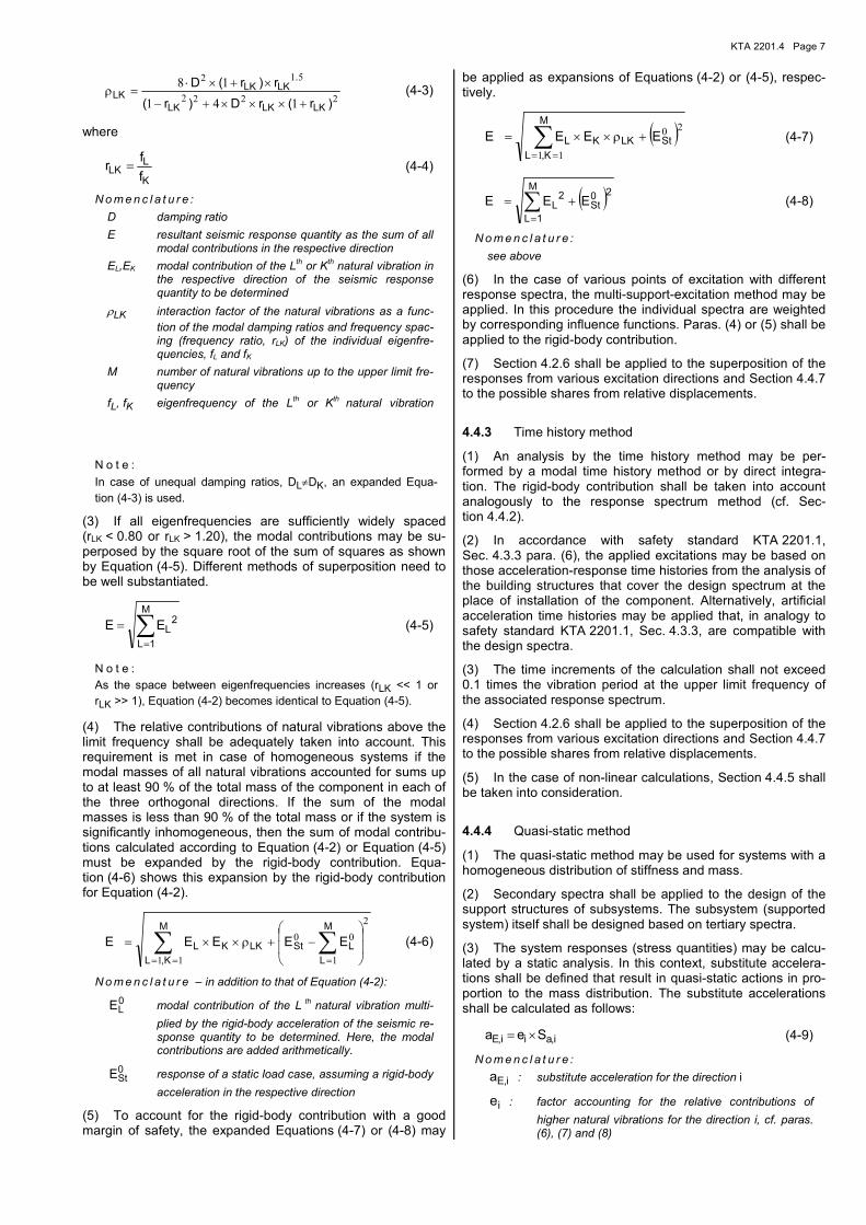
(2) In the case of components that are modeled as a system with more than one degree of freedom, the maximum re-sponse values to the individual natural vibrations (e.g., stress resultants, accelerations, deformations) shall be superposed. In this context, the method of the complete quadratic combi-nation (CQC) in accordance with Equations (4-2) shall be applied.
∑==
××=M
,KL
LKKL ρEEE
11
(4-2)
For a constant damping ratio, D, the interaction factor, ρLK,is
given by
KTA 2201.4 Page 7
2222
512
141
18
)r(rD)r(
r)r(D
LKLKLK
.LKLK
LK+×××+−
×+×⋅=ρ (4-3)
where
K
LLK
f
fr = (4-4)
N o m e n c l a t u r e :
D damping ratio
E resultant seismic response quantity as the sum of all modal contributions in the respective direction
EL,EK modal contribution of the Lth or Kth natural vibration in the respective direction of the seismic response quantity to be determined
ρLK interaction factor of the natural vibrations as a func-
tion of the modal damping ratios and frequency spac-ing (frequency ratio, rLK) of the individual eigenfre-quencies, fL and fK
M number of natural vibrations up to the upper limit fre-quency
fL, fK eigenfrequency of the Lth or Kth natural vibration
N o t e :
In case of unequal damping ratios, DL≠DK, an expanded Equa-
tion (4-3) is used.
(3) If all eigenfrequencies are sufficiently widely spaced (rLK < 0.80 or rLK > 1.20), the modal contributions may be su-perposed by the square root of the sum of squares as shown by Equation (4-5). Different methods of superposition need to be well substantiated.
∑=
=M
1L
2LEE (4-5)
N o t e :
As the space between eigenfrequencies increases (rLK << 1 or
rLK >> 1), Equation (4-2) becomes identical to Equation (4-5).
(4) The relative contributions of natural vibrations above the limit frequency shall be adequately taken into account. This requirement is met in case of homogeneous systems if the modal masses of all natural vibrations accounted for sums up to at least 90 % of the total mass of the component in each of the three orthogonal directions. If the sum of the modal masses is less than 90 % of the total mass or if the system is significantly inhomogeneous, then the sum of modal contribu-tions calculated according to Equation (4-2) or Equation (4-5) must be expanded by the rigid-body contribution. Equa-tion (4-6) shows this expansion by the rigid-body contribution for Equation (4-2).
∑ ∑== =
−+ρ××=
M
K,L
M
L
LStLKKL EEEEE
11
2
1
00 (4-6)
N o m e n c l a t u r e – in addition to that of Equation (4-2):
0LE modal contribution of the L th natural vibration multi-
plied by the rigid-body acceleration of the seismic re-sponse quantity to be determined. Here, the modal contributions are added arithmetically.
0StE
response of a static load case, assuming a rigid-body
acceleration in the respective direction
(5) To account for the rigid-body contribution with a good margin of safety, the expanded Equations (4-7) or (4-8) may
be applied as expansions of Equations (4-2) or (4-5), respec-tively.
( )∑==
+ρ××=M
K,L
StLKKL EEEE
11
20 (4-7)
( )∑=
+=M
1L
20St
2L EEE (4-8)
N o m e n c l a t u r e :
see above
(6) In the case of various points of excitation with different response spectra, the multi-support-excitation method may be applied. In this procedure the individual spectra are weighted by corresponding influence functions. Paras. (4) or (5) shall be applied to the rigid-body contribution.
(7) Section 4.2.6 shall be applied to the superposition of the responses from various excitation directions and Section 4.4.7 to the possible shares from relative displacements.
4.4.3 Time history method
(1) An analysis by the time history method may be per-formed by a modal time history method or by direct integra-tion. The rigid-body contribution shall be taken into account analogously to the response spectrum method (cf. Sec-tion 4.4.2).
(2) In accordance with safety standard KTA 2201.1, Sec. 4.3.3 para. (6), the applied excitations may be based on those acceleration-response time histories from the analysis of the building structures that cover the design spectrum at the place of installation of the component. Alternatively, artificial acceleration time histories may be applied that, in analogy to safety standard KTA 2201.1, Sec. 4.3.3, are compatible with the design spectra.
(3) The time increments of the calculation shall not exceed 0.1 times the vibration period at the upper limit frequency of the associated response spectrum.
(4) Section 4.2.6 shall be applied to the superposition of the responses from various excitation directions and Section 4.4.7 to the possible shares from relative displacements.
(5) In the case of non-linear calculations, Section 4.4.5 shall be taken into consideration.
4.4.4 Quasi-static method
(1) The quasi-static method may be used for systems with a homogeneous distribution of stiffness and mass.
(2) Secondary spectra shall be applied to the design of the support structures of subsystems. The subsystem (supported system) itself shall be designed based on tertiary spectra.
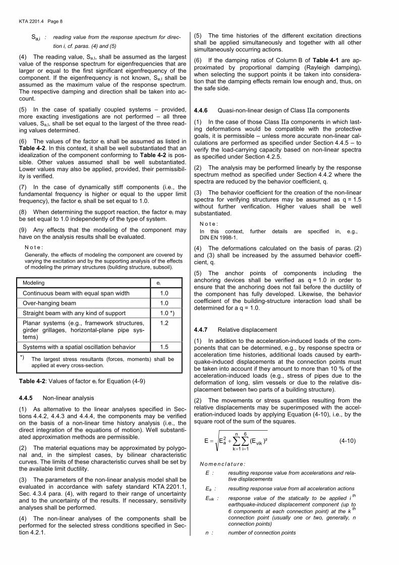
(3) The system responses (stress quantities) may be calcu-lated by a static analysis. In this context, substitute accelera-tions shall be defined that result in quasi-static actions in pro-portion to the mass distribution. The substitute accelerations shall be calculated as follows:
i,aii,E Sea ×= (4-9)
N o m e n c l a t u r e :
i,Ea : substitute acceleration for the direction i
ie : factor accounting for the relative contributions of
higher natural vibrations for the direction i, cf. paras. (6), (7) and (8)
KTA 2201.4 Page 8
i,aS : reading value from the response spectrum for direc-
tion i, cf. paras. (4) and (5)
(4) The reading value, Sa,I, shall be assumed as the largest value of the response spectrum for eigenfrequencies that are larger or equal to the first significant eigenfrequency of the component. If the eigenfrequency is not known, Sa,I shall be assumed as the maximum value of the response spectrum. The respective damping and direction shall be taken into ac-count.
(5) In the case of spatially coupled systems – provided, more exacting investigations are not performed – all three values, Sa,I, shall be set equal to the largest of the three read-ing values determined.
(6) The values of the factor ei shall be assumed as listed in Table 4-2. In this context, it shall be well substantiated that an idealization of the component conforming to Table 4-2 is pos-sible. Other values assumed shall be well substantiated. Lower values may also be applied, provided, their permissibil-ity is verified.
(7) In the case of dynamically stiff components (i.e., the fundamental frequency is higher or equal to the upper limit frequency), the factor ei shall be set equal to 1.0.
(8) When determining the support reaction, the factor ei may be set equal to 1.0 independently of the type of system.
(9) Any effects that the modeling of the component may have on the analysis results shall be evaluated.
N o t e :
Generally, the effects of modeling the component are covered by varying the excitation and by the supporting analysis of the effects of modeling the primary structures (building structure, subsoil).
4.4.5 Non-linear analysis
(1) As alternative to the linear analyses specified in Sec-tions 4.4.2, 4.4.3 and 4.4.4, the components may be verified on the basis of a non-linear time history analysis (i.e., the direct integration of the equations of motion). Well substanti-ated approximation methods are permissible.
(2) The material equations may be approximated by polygo-nal and, in the simplest cases, by bilinear characteristic curves. The limits of these characteristic curves shall be set by the available limit ductility.
(3) The parameters of the non-linear analysis model shall be evaluated in accordance with safety standard KTA 2201.1, Sec. 4.3.4 para. (4), with regard to their range of uncertainty and to the uncertainty of the results. If necessary, sensitivity analyses shall be performed.
(4) The non-linear analyses of the components shall be performed for the selected stress conditions specified in Sec-tion 4.2.1.
(5) The time histories of the different excitation directions shall be applied simultaneously and together with all other simultaneously occurring actions.
(6) If the damping ratios of Column B of Table 4-1 are ap-proximated by proportional damping (Rayleigh damping), when selecting the support points it be taken into considera-tion that the damping effects remain low enough and, thus, on the safe side.
4.4.6 Quasi-non-linear design of Class IIa components
(1) In the case of those Class IIa components in which last-ing deformations would be compatible with the protective goals, it is permissible – unless more accurate non-linear cal-culations are performed as specified under Section 4.4.5 – to verify the load-carrying capacity based on non-linear spectra as specified under Section 4.2.5.
(2) The analysis may be performed linearly by the response spectrum method as specified under Section 4.4.2 where the spectra are reduced by the behavior coefficient, q.
(3) The behavior coefficient for the creation of the non-linear spectra for verifying structures may be assumed as q = 1.5 without further verification. Higher values shall be well substantiated.
N o t e :
In this context, further details are specified in, e.g., DIN EN 1998-1.
(4) The deformations calculated on the basis of paras. (2) and (3) shall be increased by the assumed behavior coeffi-cient, q.
(5) The anchor points of components including the anchoring devices shall be verified as q = 1.0 in order to ensure that the anchoring does not fail before the ductility of the component has fully developed. Likewise, the behavior coefficient of the building-structure interaction load shall be determined for a q = 1.0.
4.4.7 Relative displacement
(1) In addition to the acceleration-induced loads of the com-ponents that can be determined, e.g., by response spectra or acceleration time histories, additional loads caused by earth-quake-induced displacements at the connection points must be taken into account if they amount to more than 10 % of the acceleration-induced loads (e.g., stress of pipes due to the deformation of long, slim vessels or due to the relative dis-placement between two parts of a building structure).
(2) The movements or stress quantities resulting from the relative displacements may be superimposed with the accel-eration-induced loads by applying Equation (4-10), i.e., by the square root of the sum of the squares.
∑∑= =
+=n
1k
6
1ivik
2a )²E(EE (4-10)
N o m e n c l a t u r e :
E : resulting response value from accelerations and rela-tive displacements
Ea : resulting response value from all acceleration actions
Evik : response value of the statically to be applied i th
earthquake-induced displacement component (up to 6 components at each connection point) at the k
th
connection point (usually one or two, generally, n connection points)
n : number of connection points
Modeling ei
Continuous beam with equal span width 1.0
Over-hanging beam 1.0
Straight beam with any kind of support 1.0 *)
Planar systems (e.g., framework structures, girder grillages, horizontal-plane pipe sys-tems)
1.2
Systems with a spatial oscillation behavior 1.5
*) The largest stress resultants (forces, moments) shall be applied at every cross-section.
Table 4-2: Values of factor ei for Equation (4-9)
KTA 2201.4 Page 9
4.5 Verification of the Limit Conditions
4.5.1 Basics
(1) The loads (e.g., stress resultants, stresses, deforma-tions, accelerations) determined for seismic actions together with other actions as specified under Section 4.4 shall be cor-related with the respective permissible strains. The permissi-ble strains result from the limit conditions of
a) load-carrying capacity,
b) integrity, and
c) functional capability.
(2) The limit conditions may be determined linearly or non-linearly from the stress quantities or from the displacement quantities.
(3) The verification of action combinations for the design basis earthquake shall be based on Requirement Category A3 in accordance with KTA-GS-78 unless deviating requirements are specified below.
(4) The correlation of the Requirement Categories in accor-dance with KTA-GS-78 with the loading levels of steel engi-neering, i.e., the design limits of structural engineering and, in particular, the service limit levels of plant engineering, is pre-sented in Table 4-3. Depending on the individual case, a more conservative categorization is permissible.
(5) The verifications may be carried out by the partial safety concept specified under Section 4.5.2 or by the global safety concept (stress analysis) specified under Section 4.5.3. In the case of stability problems, the verification shall be carried out as specified under Section 4.5.2.
Designation: Source
Classification
Service Limit Levels of me-chanical engi-neering: KTA 3201.2 KTA 3211.2
A B C D
Loading Levels: KTA 3205.1 KTA 3205.2
H HZ HS1 HS2/3
Design load situations: DIN EN 1990 DIN EN 1993
permanent and variable
accidental
Requirement Categories: KTA-GS-78
A1 A2 A3
Table 4-3: Classification of the requirement categories
(6) The verifications shall be differentiated according to
a) Rod and bar structures (e.g., support structures of com-ponents), and
b) Shell and plate structures of components with or without pressurization (e.g., vessel walls, support skirts, pipes, fit-tings).
(7) The verification of action combinations with the design basis earthquakes shall only be performed for primary stress-es unless deviating requirements are specified below.
N o t e :
Secondary and peak stresses are specified in component-specific standards.
(8) In the case of components consisting of brittle materials (e.g., cast iron, ceramics) or of unfavorably constructed com-ponents (e.g., with fillet welds), the total stress shall be taken into account in addition to the primary stresses. In this context, the secondary stresses and peak stresses shall either be treated as primary stresses or shall, in addition to the primary stresses, be evaluated with regard to their respective failure mode.
(9) If the mechanical design does not ensure a sufficient deformation capacity (ductility) of the component or its support structure, then the design basis earthquake shall be catego-rized in Requirement Category A2.
(10) With regard to load-carrying capacity (and, if danger of flooding exists, also with regard to integrity), the Class IIa components shall be verified in the same way as Class I com-ponents if their loading from seismic actions were determined as specified in Section 4.4.6 (quasi-nonlinear design). Special attention shall be given to paras. (3), (4) and (5) of Sec-tion 4.4.6.
(11) The mathematical analysis of the active and passive functional capability shall be performed by verifying the defor-mation as specified under para. (12) or by the stress analysis as specified under para. (13).
(12) The deformation verification shall prove that the deter-mined deformations do not adversely affect the required func-tionality. In this context, it shall be differentiated between:
a) Functional capability is required only after the earth-quake. The verification shall be based on the resulting permanent deformations.
b) Functional capability is required also during the earth-quake. The verification shall be based on the resulting to-tal deformations (elastic plus permanent deformations).
(13) If the verification by way of stress analysis is chosen, it shall be based on more stringent limit values as follows:
a) If an active functional capability is required only after an earthquake or if only a passive functional capability is re-quired, it is sufficient to assume Service Limit Level C for the design basis earthquake.
b) If an active functional capability is also required during an earthquake, Service Limit Level B shall be assumed for the design basis earthquake.
c) With regard to ensuring the flow in passive components (e.g., pipes, heat exchangers), it is sufficient to assume Service Limit Level D, provided, an elastic analysis is ba-sis for the verification of the component.
N o t e :
Details are specified in component-specific standards. The verifi-cation of functional capability by stress analysis specified under this para. (13) covers the verification of the load-carrying capaci-ties for the respective regions.
4.5.2 Verification by the partial safety concept
(1) In accordance with DIN EN 1990, the following actions shall be taken into account:
a) Permanent actions, Gk, (characteristic value),
b) Variable actions, Qk, (characteristic value),
c) Actions from the design basis earthquake, AEd (design basis earthquake in accordance with safety standard KTA 2201.1).
KTA 2201.4 Page 10
(2) The permanent actions and variable actions shall be assumed as the corresponding characteristic values.
N o t e :
Actions from earthquakes are design values and implicitly contain a partial safety factor γF = 1.0. In accordance with DIN EN 1990,
the design value, AEd, covers both the weighting factor, γ1, and the importance factor, γ, for the design basis earthquake in accor-dance with safety standard KTA 2201.1.
(3) The design value for the earthquake loading shall be calculated by Equation (4-11) in accordance with DIN EN 1990 as the action combination of the limit conditions of the load-carrying capacity and of the serviceability:
{ }∑≥
×ψ⊕⊕=1
2
i
i,ki,Edkd )Q(AGEE (4-11)
N o m e n c l a t u r e :
Ed : design value for the earthquake loading
{ }...E : earthquake loading function
Gk : characteristic value of permanent action
Qk : characteristic value of variable action
AEd : actions from design basis earthquake
ψ2 : combination coefficient
⊕ : indicates “shall be combined with”
∑ : indicates “combined effect of”
(4) The combination coefficients, ψ2, for the variable actions
shall be specified such that the product of ψ2 and QK would
describe the quasi-permanent value of the respective variable action. Accordingly, the combination coefficients, ψ2, for the
quasi-permanent imposed loads and prior deformation re-straints shall be assumed as ψ2 = 1.0.
N o t e :
The combination coefficients, ψ2, are defined in DIN EN 1990.
Reference values for ψ2 are specified in safety standard
KTA 2201.3.
(5) For the ultimate limit condition it shall be verified that
dd RE ≤ (4-12)
where
{ }Mkd /fRR γ= (4-13)
is the material specific design value of the bearing capacity which in turn is a function of the ratio of the characteristic value of material strength, fK, and the respective partial safety factor, γM. In the case of structural steel, three different partial
safety factors, γM, shall be considered:
- γM0: stress analysis of the cross-section,
- γM1: verification of the stability of components with respect
to flexural buckling and torsional buckling,
- γM2: verification of the tensile strength for the net cross-
section.
(6) The partial safety factors γM0 and γM1 shall be assumed
as being equal to 1.0. With respect to the tensile-strength-dependent permissible strain, the value of γM2 shall be as-
sumed as being equal to 1.15.
(7) Unless more detailed requirements are specified in the component-specific standards, the design value of the bearing capacity may be determined by Equation (4-14).
zuldR σ= (4-14)
where σzul is the permissible stress for the respective require-ment category in accordance with the corresponding compo-nent-specific standards.
(8) Bar-shaped elements of components outside of the scope of the component-specific nuclear standards may be verified in accordance with DIN EN 1993-1-1.
(9) Shell-shaped elements of components outside of the scope of the component-specific nuclear standards may be verified by applying Equation (4-14) in combination with pa-ra. (4) of Section 4.5.3.
(10) When verifying the secure positioning (tilting, slipping) of unanchored components for the design basis earthquake, a safety factor equal to 0.95 shall be assumed for stabilizing actions and equal to 1.0 for destabilizing actions.
(11) For the limit condition of the functional capability or of the integrity it shall be verified that
dd CE ≤ (4-15)
where Ed is the design value of the earthquake loading (e.g., stress, deformation) according to Equation (4-11) and Cd is the design value of the functional capability or of the integrity (e.g., permissible stress or deformation). This latter value shall be specified for the individual component and the individual case.
4.5.3 Verification by the global safety concept
(1) This verification shall be based on the action combina-tions in accordance with the corresponding component-specific standards.
(2) The permissible strains (e.g., permissible stress, defor-mations) in accordance with corresponding component-specific standards shall be applied.
(3) A stress analysis shall be performed for the ultimate limit condition and the limit condition of the integrity to verify that
zulvorh σ≤σ (4-16)
where σvorh is the strain for the decisive action combination determined as specified under para. (1) and σzul is the deci-
sive permissible strain specified under para. (2). The limit condition of the functional capability shall be verified as speci-fied under Section 5 or under Section 4.5.1, para. (11).
N o t e :
Equation (4-16) applies in a general sense to every kind of loading (e.g., stress, deformation, distortion).
(4) The load-carrying capacity or the integrity of shell-shaped elements of components outside of the scope of the component-specific nuclear standards may be verified based on the primary stresses listed in Table 4-4. This limitation to a primary stress analysis is only permissible if the design and the materials are in accordance with safety standard series KTA 3211.
(5) When verifying the secure positioning (tilting, slipping) of unanchored components for the design basis earthquake, a safety factor equal to 0.95 shall be assumed for stabilizing actions and equal to 1.0 for destabilizing actions.
KTA 2201.4 Page 11
Requirement Category or Service Limit Level
Pm
Pm + Pb or
Pl + Pb
A3 or D 0.7 × Rm α × 0.7 × Rm
A2 or C 1.0 × Rp0.2 α × 1.0 × Rp0.2
N o m e n c l a t u r e :
Pm general membrane stress from the design value of loading during the earthquake situation
Pl local primary membrane stress from the design value of loading during the earthquake situation
Pb primary bending stress from the design value of loading during the earthquake situation
Rm characteristic value of the tensile strength of the material
Rp0.2 characteristic value of the yield strength or 0.2 % proof stress of the material
α form factor depending on the cross-section (e.g., α = 1.5 for rectangular cross-sections)
Table 4-4: Limit conditions of the primary stresses of other components
5 Verification by Physical Experiments
5.1 Verification Objective
(1) The verification objective of the test shall be derived from the respective safety-related tasks.
(2) With respect to the requirements derived from the verifi-cation objective for the limit values to be observed, it shall be specified whether these limit values must be determined dur-ing the test.
5.2 Requirements Regarding the Test Object
(1) Physical experiments for the verification of seismic safety may be performed on components (component or individual devices) – hereinafter generally referred to as ‘test objects’ – either in a test bay or in their installed condition in the nuclear power plant.
(2) These experiments shall be performed on original com-ponents or, preferably, on design-identical components. Sub-stitute components may be used if they represent the proper-ties of the original components with respect to the respective verification objective.
(3) If the same test object is used for several partial tests, it shall be ensured that the test object continues to have those properties of the original component that are essential to the respective test.
(4) If the experiment is performed in a test bay, the test ob-ject shall be mounted in such a way that the original boundary conditions with respect to the verification objective are repre-sented.
(5) The influence of existing oscillation insulations shall be taken into account. This may be accounted for either in the mounting of the test object or when determining the action quantities.
(6) If a position other than the specified in-plant mounting position of the test object is used in an experiment, the changed influence of gravity shall be taken into consideration.
(7) As far as necessary, connections to neighboring compo-nents shall be taken into account.
(8) If necessary with regard to the verification objective, all operating conditions for the test object that must be postulated for the seismic event (e.g., pressure, temperature, voltage, electric current, limit values to be observed) shall be deter-mined. If the operating conditions are only partly or not at all accounted for by the experiment, their effects shall be ac-counted for by some other means (e.g., by analysis).
5.3 Requirements Regarding Excitation of Oscillation
5.3.1 Basics
(1) The excitation of oscillation for the verification by physi-cal experiments shall be determined under consideration of the type of excitation as specified under Sections 4.2 and 5.5.
(2) The decisive action for the experiment shall be specified for the respective assumptions (e.g. static substitute loads, response spectrum, time history) as well as for the respective test signal in the excitation directions at the place of installa-tion.
(3) The test object shall be excited at its anchor points in such a way that it receives at least the specified actions. Any deviations shall be well substantiated.
(4) The selected excitation shall, basically, be equivalent to the decisive seismic action. In case of an excitation by means of forced oscillations as specified in para. (1) item c) of Sec-tion 5.3.6, the equivalency shall preferably be verified by com-paring the response spectra. Other verification methods, e.g., by the spectral power density, are permissible.
(5) A deviation from the requirement of equivalency between excitation and seismic action is permissible, provided, it is possible to achieve the verification objective by extrapolation (e.g., for stresses in the linear range).
5.3.2 Comparison of Actions
(1) A comparison of the actions shall be performed in order to ensure that the required actions are achieved by the test.
(2) The actions shall, preferably, be compared based on the response spectra. In the evaluation, the damping of the re-sponse spectrum shall be larger than or equal to the corre-sponding value of the required spectrum.
a) In case of an unknown oscillation behavior of the test object, it shall be ensured that the required response spectra are achieved by the entirety of applied test exci-tations.
b) If the characteristic frequencies of the test object are known, it is sufficient if the individual test signals envelop the required response spectra in the range of these fre-quencies. The verification shall be carried out for these characteristic frequencies and, additionally, for frequen-cies ± 10 % away from the characteristic frequencies. The equivalency shall be verified for reliably determined damping values or for the respective damping value to be applied according to Column A of Table 4-1.
(3) When calculating the test response spectrum, the spac-ing of the support points shall be adjusted to the respective damping ratio in order to detect if the test response spectrum falls below the required response spectrum.
(4) In the case of damping ratios from 1 % to 5 %, the max-imum calculation increments shall be 1/12 of an octave and from 5 % to 10 % 1/6 of an octave. Even higher damping ra-tios would permit increasing the calculation increments up to 1/3 of an octave.
KTA 2201.4 Page 12
5.3.3 Excitation Axes
(1) Basically, the excitations of the test shall be applied si-multaneously in all three spatial directions.
(2) An individualization of the sequence of the individual direction-related loads is permissible, provided,
a) the verification objective allows for the superposition of the corresponding reactions of the test object, or
b) it is shown that the behavior of the test object (eigenfre-quencies, stiffness) or that the required response spectra (frequency ranges with large resonance peaks) are inde-pendent of each other with respect to the individual axes, or
c) the multi-axial character of the seismic excitation is taken into account by means of a correspondingly higher test excitation (cf. Section 5.5.2).
(3) In the case of multi-axial test excitations with a fixed phase assignment, the in-phase and 180°-phase-offset excita-tion signals shall normally be combined.
5.3.4 Transverse motions
(1) Movements orthogonal to the respective direction or plane of excitation shall be measured.
(2) If transverse motions occur, it shall be ensured that the required value in the direction of excitation is achieved.
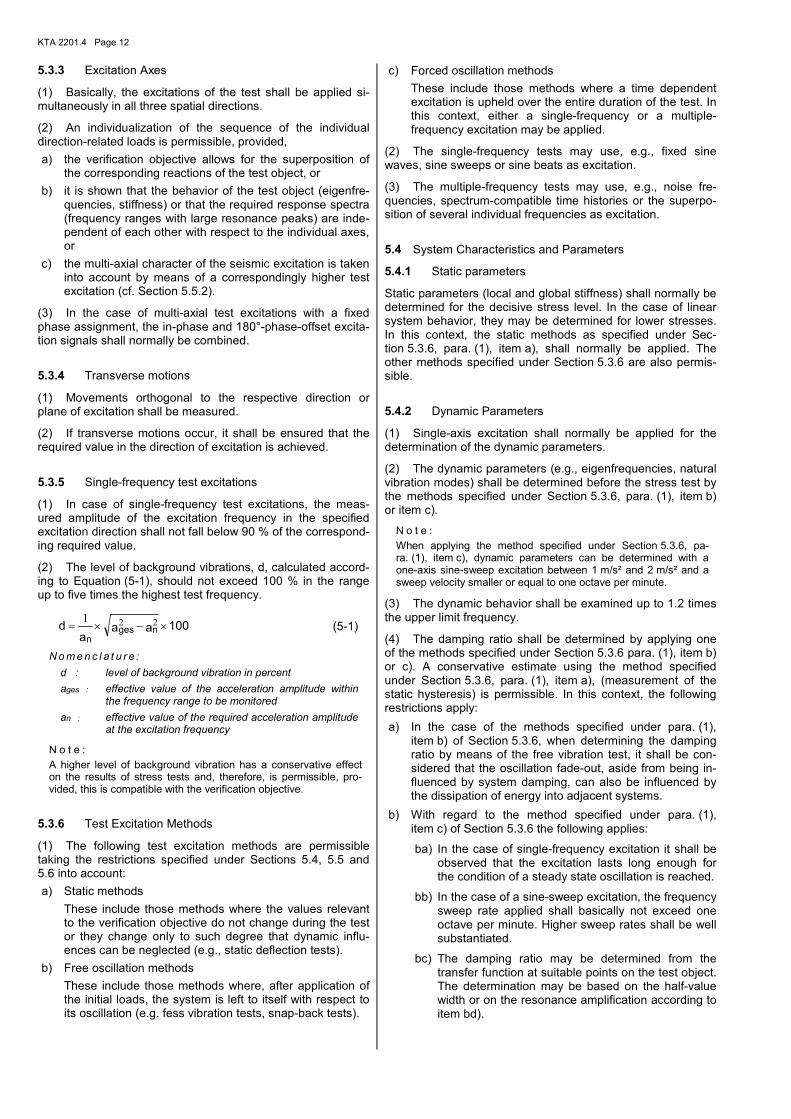
5.3.5 Single-frequency test excitations
(1) In case of single-frequency test excitations, the meas-ured amplitude of the excitation frequency in the specified excitation direction shall not fall below 90 % of the correspond-ing required value.
(2) The level of background vibrations, d, calculated accord-ing to Equation (5-1), should not exceed 100 % in the range up to five times the highest test frequency.
100aaa
d ngesn
×−×= 221 (5-1)
N o m e n c l a t u r e :
d : level of background vibration in percent
ages : effective value of the acceleration amplitude within the frequency range to be monitored
an : effective value of the required acceleration amplitude at the excitation frequency
N o t e :
A higher level of background vibration has a conservative effect on the results of stress tests and, therefore, is permissible, pro-vided, this is compatible with the verification objective.
5.3.6 Test Excitation Methods
(1) The following test excitation methods are permissible taking the restrictions specified under Sections 5.4, 5.5 and 5.6 into account:
a) Static methods
These include those methods where the values relevant to the verification objective do not change during the test or they change only to such degree that dynamic influ-ences can be neglected (e.g., static deflection tests).
b) Free oscillation methods
These include those methods where, after application of the initial loads, the system is left to itself with respect to its oscillation (e.g. fess vibration tests, snap-back tests).
c) Forced oscillation methods
These include those methods where a time dependent excitation is upheld over the entire duration of the test. In this context, either a single-frequency or a multiple-frequency excitation may be applied.
(2) The single-frequency tests may use, e.g., fixed sine waves, sine sweeps or sine beats as excitation.
(3) The multiple-frequency tests may use, e.g., noise fre-quencies, spectrum-compatible time histories or the superpo-sition of several individual frequencies as excitation.
5.4 System Characteristics and Parameters
5.4.1 Static parameters
Static parameters (local and global stiffness) shall normally be determined for the decisive stress level. In the case of linear system behavior, they may be determined for lower stresses. In this context, the static methods as specified under Sec-tion 5.3.6, para. (1), item a), shall normally be applied. The other methods specified under Section 5.3.6 are also permis-sible.
5.4.2 Dynamic Parameters
(1) Single-axis excitation shall normally be applied for the determination of the dynamic parameters.
(2) The dynamic parameters (e.g., eigenfrequencies, natural vibration modes) shall be determined before the stress test by the methods specified under Section 5.3.6, para. (1), item b) or item c).
N o t e :
When applying the method specified under Section 5.3.6, pa-ra. (1), item c), dynamic parameters can be determined with a one-axis sine-sweep excitation between 1 m/s² and 2 m/s² and a sweep velocity smaller or equal to one octave per minute.
(3) The dynamic behavior shall be examined up to 1.2 times the upper limit frequency.
(4) The damping ratio shall be determined by applying one of the methods specified under Section 5.3.6 para. (1), item b) or c). A conservative estimate using the method specified under Section 5.3.6, para. (1), item a), (measurement of the static hysteresis) is permissible. In this context, the following restrictions apply:
a) In the case of the methods specified under para. (1), item b) of Section 5.3.6, when determining the damping ratio by means of the free vibration test, it shall be con-sidered that the oscillation fade-out, aside from being in-fluenced by system damping, can also be influenced by the dissipation of energy into adjacent systems.
b) With regard to the method specified under para. (1), item c) of Section 5.3.6 the following applies:
ba) In the case of single-frequency excitation it shall be observed that the excitation lasts long enough for the condition of a steady state oscillation is reached.
bb) In the case of a sine-sweep excitation, the frequency sweep rate applied shall basically not exceed one octave per minute. Higher sweep rates shall be well substantiated.
bc) The damping ratio may be determined from the transfer function at suitable points on the test object. The determination may be based on the half-value width or on the resonance amplification according to item bd).
KTA 2201.4 Page 13
bd) A lower limit boundary for the damping ratio, D, of the test object may be calculated by Equation (5-2).
100Q2
1D ⋅
⋅= (5-2)
N o m e n c l a t u r e :
D : damping ratio of test object in percent
Q : resonance peak
N o t e :
Equation (5-2) is exactly true only for an oscillator with one degree of freedom.
5.5 Analysis of Mechanical Behavior and Determination of Stress
5.5.1 Methods
The following methods shall be applied when determining the stresses on the test object:
a) Static methods
If the action quantity is based on an applied deflection force that was determined from the substitute accelera-tion, aE,i, according to Equation (4-9), then the static methods specified under para. (1), item a) of Sec-tion 5.3.6 shall normally be applied only to systems with a sufficiently homogeneous distribution of mass. In this context, prerequisite for the determination of aE,i is the knowledge or a conservative estimate of the damping ra-tio of the test object (e.g., values from Column A of Table 4-1).
b) Free oscillation method
It shall be ensured that the required acceleration, aE,i, according to Equation (4-9) is applied during at least one cycle of the free oscillations. This method is particularly suited for components with a sufficiently homogeneous distribution of mass.
c) Forced oscillation method
The stress may be determined by applying the method of forced oscillations as specified under para. (1), item c) of Section 5.3.6.
5.5.2 Base excitation
5.5.2.1 General requirements
(1) The excitation of the test object shall basically be meas-ured at the mounting points of the test object. This require-ment may be deviated from, provided, the oscillations at the measurement point and at the anchor point are identical with regard to phase and amplitude.
(2) Basically, the damping ratio shall be determined for dis-tinctive low eigenfrequencies. This requirement may deviated from, provided, the values of Column A of Table 4-1 are ap-plied.
(3) The values of Column A of Table 4-1 shall be applied as damping ratios for higher eigenfrequencies if the damping cannot be accurately determined by experiments (e.g., from the transfer behavior).
5.5.2.2 Single-frequency excitation in case of unknown eigenfrequencies of the test object
(1) In the case of a single-frequency excitation and unknown eigenfrequencies of the test object, the excitation shall be adjusted such that the test response spectrum envelops the
required response spectrum as specified under Section 5.3.2.
(2) The excitation amplitude of the single-frequency excita-tion in the direction i shall be calculated by Equation (5-3).
)D,f(Ü
)D,f(ak)f(A i
ii ×= (5-3)
N o m e n c l a t u r e :
i : index for direction x, y, (horizontal) and z (verti-cal)
f : excitation frequency in Hz
D : damping ration of the test object
ai(f, D) : acceleration of the response spectrum in direc-
tion i
Ü(f, D) : excitation-specific amplification factor as speci-fied in Figure 5-1 or Figure 5-2 (depending on the excitation form)
ki : factor for measuring the relative shares of sev-eral natural vibrations if only one natural vibration is excited at a time.
ki = 1, if several natural vibrations are excited si-multaneously or if only one natural vibration lies in the test frequency range.
ki = 2 , if only one natural vibration is excited at
a time and several characteristic modes lie in the test frequency range.
The excitation shall be applied up to the upper limit frequency of the required response spectrum.
An additional test of the rigid-body acceleration shall be per-formed with at least one period of a freely selected excitation frequency that shall be unequal to an eigenfrequency and smaller than the upper limit frequency.
oiii ak)f(A ×= (5-4)
w h e r e
(additionally)
a0i : rigid-body acceleration (zero-period accelera-tion) in the direction i
(3) If time histories of the excitation for the place of installa-tion are available, the excitation may be calculated by Equa-tion (5-5).
oieffii ark)f(A ××= (5-5)
with
( )
( ) 1excitationfrequencysingleeffa
excitationhistorytimeeffa
effr ≤= (5-6)
N o m e n c l a t u r e
reff : ratio of the effective values occurring in a time-history excitation and the effective values occurring in a harmonic excitation.
The respective effective value, aeff, shall be determined by Equation (5-7).
∫+
×=
Tt
t
eff dt)t(aT
a
0
0
21 (5-7)
N o m e n c l a t u r e :
a(t) : time-dependent acceleration response function
T : period length
t0 : starting time
KTA 2201.4 Page 14
Figure 5-1: Resonance amplification factors for a sine wave excitation and for a sine beat excitation at constant frequency
Figure 5-2: Resonance amplification factors for sine sweep excitation
KTA 2201.4 Page 15
5.5.2.3 Single-frequency excitation in case of known ei-genfrequencies of the test object
(1) If the eigenfrequencies of the test object are known and lie within the test frequency range, it is sufficient to perform the test at these eigenfrequencies. In this case, the respec-tive test response spectrum at these locations shall reach or exceed the response spectrum.
(2) In the case of test objects with a rigid-body behavior, it is sufficient to perform the test with a static excitation with the rigid-body acceleration. In case of a dynamic excitation, the rigid-body acceleration may be calculated by Equation (5-4). The excitation may be performed with a freely selected fre-quency that is lower than or equal to the upper limit fre-quency, and it shall be applied for a complete period of the excitation frequency.
(3) Depending on the type of excitation at the place of in-stallation, one of the procedures under para. (1) or para. (2) shall be applied to the determination of the acceleration of the response spectrum, ai(f,D), in the direction i.
5.5.2.4 Multiple-frequency excitation
(1) In case specified time histories are available for the earthquake excitation, these time histories may be applied as test input. The validity of the test time histories shall be estab-lished by comparing their response spectra with the specified time history specified under Section 5.3.2
(2) If more than three specified time histories are available, three representative time histories may be selected as test input signals.
(3) If the test is performed with artificial time histories, with noise signals or with multiple-frequency signals, a complete signal shall be used. In this case, one test run is sufficient. A complete signal is considered to be one that envelops the required response spectrum between the upper and lower frequency limits as specified under Section 5.3.2.
(4) The artificial time histories shall be generated on the basis of the response spectra at the place of installation of the test object as specified under Section 5.3.2.
(5) If the test acceleration does not achieve the value of the rigid-body acceleration, an acceleration equal to the rigid-body acceleration shall be applied in an additional test step. This acceleration may be applied statically or dynamically and, independent of the eigenfrequencies, at any frequency less than or equal to the upper frequency limit.
5.5.2.5 Simultaneity of excitation directions
(1) If the excitation at the place of installation is dominantly two-axial (one horizontal direction, ah, and the vertical direc-tion, av), the test excitation ai(f,D) and aoi shall be determined
as follows:
a) One-axis test excitation
)D,f(a)D,f(a)D,f(a vhi
22 += (5-8)
22
v,oh,ooi aaa += (5-9)
b) Two-axis test excitation or one-axis test excitation, pro-vided, the requirements according to para. (2) item b) of Section 5.3.3 (decoupled axes) are met:
)D,f(a)D,f(a v,hi =
(5-10)
v,ohoi aa = (5-11)
N o m e n c l a t u r e :
ai(f,D) : spectral value of acceleration in direction i
a0i : rigid-body acceleration (zero period acceleration) in direction i
ah : horizontal acceleration
av : vertical acceleration
(2) If the excitation at the place of installation is three-axial, the test excitation ai(f,D) and aoi shall be determined as fol-
lows:
a) One-axis test excitation:
)D,f(a)D,f(a)D,f(a)D,f(a zyxi
222 ++= (5-12)
2oz
2oy
2oxoi aaaa ++=
(5-13)
b) Two-axis test excitation (vertical and horizontal):
vertical:
)D,f(a)D,f(a zi =
(5-14)
ozoi aa = (5-15)
horizontal:
)D,f(a)D,f(a)D,f(a yxi
22 += (5-16)
2oy
2oxoi aaa +=
(5-17)
c) Three-axis test excitation or one- or two-axis test excita-tion, provided, the requirements according to para. (2) item b) of Section 5.3.3 (decoupled axes) are met:
)D,f(a)D,f(a z,y,xi =
(5-18)
z,y,oxoi aa = (5-19)
N o m e n c l a t u r e :
cf. para. (1) above
KTA 2201.4 Page 16
5.5.3 Center-of-gravity excitation
(1) The excitation at the center of gravity (e.g., in the in-stalled condition in the plant) may only be applied in the case of components with a homogeneous distribution of mass.
(2) It shall be ensured that the required substitute accelera-tions, aEi, according to Equation (4-9) are applied,
(3) With regard to the test excitation requirements (e.g., test frequencies or test frequency range), the same requirements apply as those specified for the base excitation (cf. Sec-tion 5.5.2).
5.6 Verification of Limit Conditions
(1) The experiment-based stress analysis shall verify that the test objects fulfil their safety-related tasks as specified under Section 3.1. In this context, the stresses specified un-der Section 5.5 shall be determined.
(2) For the verification of permissibility of the stresses, the test excitation methods specified under Section 5.3.6 may be applied, with the following restrictions:
a) With respect to functional capability, the method speci-fied in para. (1), item a) of Section 5.3.6 may only be ap-plied in the case of a deformation-related failure.
b) With respect to functional capability under load, the method specified in para. (1), item b) of Section 5.3.6 may only be applied if the free vibration decay time is longer than the length of the required interval for a safe-ty-related functioning of the test object. In this context, the amplitude decrease shall also be taken into consid-eration.
(3) The following methods, among others, are permissible for the verification of safety against failure:
a) To verify the load-carrying capacity and the integrity, the proof that the limit conditions specified under Section 4.5 are not exceeded may be performed by stress or strain measurements on significant force-transmitting parts of the test objects.
b) To verify the functional capability, checks may be per-formed regarding possibly occurring deformations to en-sure that no impermissible condition occurs under load.
c) If no stresses or deformations are found, it is permissible to increase the test stress by a safety factor, γF. The safety factor, γF, shall be calculated as specified by Equation (5-20):
21 FFF γ×γ=γ (5-20)
N o m e n c l a t u r e :
γF1 : safety factor against failure, γF1 = 1.1
γF2 : safety factor for the number of test objects between
3 and 1 (transfer factor, cf. Equation (5-21))
4101 2 .. F ≤γ≤ (5-21)
In well substantiated cases the safety factor γF2 may be
reduced. If it can be proven with respect to the verifica-tion objective that the most unfavorable test object has been chosen, a safety factor γF2 = 1.0 may be used.
(4) If a verification of safety against failure is possible with the safety factor γF specified in para. (3), the verification ob-
jective is considered as having been achieved, provided,
a) a limit stress test leads to at least a safety factor γF, or
b) a test is carried out with stresses increased by the safety factor γF and the verification objective is achieved, or
c) a test with the safety factor γF = 1.0 verifies a safety
margin for the stresses or deformations, or
d) an extrapolation of a test stress condition lower than the specified earthquake stress condition verifies compli-ance with the safety against failure as specified under para. (3).
(5) Provided, the verification of load-carrying capacity, in-tegrity or functional capability is not required to comply with certain mechanical stress or strain limits, then the completed test is considered as proof of permissibility.
5.7 Combination of Several Verification Steps.
When combining several verification steps in one test step, the requirements for the contained partial steps need to be considered only to the extent as necessary for the respective verification objectives. Only the respective test objective needs to be verified.
5.8 Documentation
The documentation shall normally include the following infor-mation:
a) Regarding the test object:
- identification marking of the test object,
- identification of the test object (e.g., type, manufac-turer, technical drawing),
- data sheet (e.g., information on materials, certifica-tions),
- verification objective.
b) Regarding the layout of the test:
- description of the equipment for testing, measuring and data collection,
- test conditions,
- diagram of measuring points.
c) Regarding the implementation of the test:
- date of implementation of the test,
- test laboratory, tester,
- type of excitation signal,
- excitation amplitude,
- frequency range,
- direction of excitation,
- specific observations.
6 Verification by Analogy
(1) A verification by analogy shall be based on the following reference results:
a) the results from analytical or experimental verifications as specified under Sections 4 or 5 that were performed on similar, type-identical components,
b) the quantitatively documented results for the respective component with regard to its behavior under other ac-tions, provided, these results are suited to make com-parisons.
(2) The available reference results shall be evaluated with regard to transferability of the actions and resistances, and it shall be quantitatively substantiated that this procedure veri-fies that the respective component can fulfill its safety-related task.
KTA 2201.4 Page 17
(3) Static system characteristics (global or local stiffness) and parameters (material properties) may be used as refer-ence results, provided, the mechanical design and materials are qualitatively similar. This also applies to a non-linear be-havior which must be comparable at the respective stress levels.
(4) The dynamic system characteristics (e.g., eigen-frequencies, natural vibration modes) may be used as refer-ence if the static system characteristics are comparable and any changes with respect to mass distribution are evaluated.
(5) Higher values for the damping ratios than the ones specified under Section 4 may be applied, provided, they are well substantiated for the specific case of application..
(6) If, in limited frequency ranges, the reference excitation is smaller than the required excitation, it shall be verified that this is either negligible for the specific component or that this is covered by the higher excitation level when verifying the limit conditions.
7 Verification by Plausibility Considerations
(1) A verification by plausibility considerations shall be based on factual experience as follows:
a) Experience regarding the behavior of similar, type-identical components in nuclear or non-nuclear facilities during earthquakes that have actually occurred.
b) Experience from earthquake verifications for similar, type-identical components that enable an evaluation of the design planning or mechanical design of other com-ponents with regard to earthquake safety.
(2) The factual experience shall be evaluated with regard to transferability of the actions and resistances. On this basis it shall be substantiated in writing that it is plausible that the respective component will be able to fulfill its safety-related task.
(3) To gain factual experience as specified under para. (1), item a), and for evaluating the mechanical design as specified in para. (1), item b), it is necessary
- to peruse the design documents, and
- to perform walk-through inspections of the plant.
The observations made in this context shall be documented in writing.
(4) Walk-through inspections shall normally be performed according to the schematic sequence shown in Figure 7-1.
Walk-through inspections shall be performed in the actual power plant. If a CAD model is available, they can also be performed as a virtual walk-through. Prerequisite in the latter context is that the CAD model and all data relevant to the evaluation are current and quality assured.
(5) The evaluation and application of the walk-through in-spection results shall be well substantiated. The substantiat-ing criteria shall be based on the requirements that must be met (i.e., load-carrying capacity, integrity, functional capabil-ity).
Preparation
• Specifying walk-through goals
• Appointing walk-through team members
• Procuring walk-through documents
o Room lists
o System circuit diagrams
o Component arrangement plans (e.g., piping plans)
• Reviewing the walk-through conditions (e.g., radiation exposure, accessibility)
Execution
• Identifying the components (in the plant or within the CAD model)
• Documenting relevant observations (protocols)
Evaluation
with respect to the walk-through objectives
• Significance
• Transferability
Post-processing
• Complementing the documents
• Editing the protocols
• Additional verifications
• Integration into plausibility verifications
Figure 7-1: Schematic sequence of walk-through inspec-tions
KTA 2201.4 Page 18
Appendix A
Regulations Referred to in this Safety Standard
(Regulations referred to in this safety standard are valid only in the versions cited below. Regulations which are referred to within these regulations are valid only in the version that was valid when the latter regulations were established or issued.)
AtG Act on the peaceful utilization of atomic energy and the protection against its haz-ards (Atomic Energy Act – AtG) of December 23, 1959, revised version of July 15, 1985 (BGBl. I, p. 1565), most recently changed by Article 5, Sec. 6 of the Act of February 24, 2012 (BGBl. I, p. 212)
StrlSchV Ordinance on the protection from damage by ionizing radiation (Radiological Protection Ordinance – StrlSchV) of July 20, 2001 (BGBl. I, p. 1714; 2002 I, p. 1459), most recently changed by Article 5, Sec. 7 of the Act of February 24, 2012 (BGBl. I, p. 212)
Safety Criteria (1977-10) Safety criteria for nuclear power plants of October 21, 1977 (BAnz. No. 206 of No-vember 3, 1977)
Design Basis Acci-dent Guidelines
(1983-10) Guidelines for the assessment of the design of nuclear power plants with pressur-ized water reactors against design basis accidents as defined in Sec. 28, para. 3 StrlSchV (Design Basis Accident Guidelines) of October 18, 1983 (Addendum to BAnz. No. 245 of December 31, 1983)
KTA 1403 (2010-11) Ageing-management in nuclear power plants
KTA 2201.1 (2011-11) Design of nuclear power plants against seismic events; Part 1: Principles
KTA 2201.3 (E 2012-11) Design of nuclear power plants against seismic events; Part 3: Design of structural components – Draft safety standard
KTA 3201.2 (ÄE 2010-11) Design of reactor cores of pressurized water and boiling water reactors; Part 2: Neutron-physical requirements for design and operation of the reactor core and adjacent systems – Draft safety standard revision
KTA 3205.1 (2002-06) Component support structures with non-integral connections Part 1: Component support structures with non-integral connections for components of the reactor coolant pressure boundary of light water reactors
KTA 3205.2 (1990-06) Component support structures with non-integral connections; Part 2: Component support structures with non-integral connections for pressure and activity-retaining components in systems outside the primary circuit
KTA 3211.1 (2000-06) Pressure- and activity-retaining components of systems outside the primary circuit Part 1: Materials
KTA 3211.2 (ÄE 2010-11) Pressure and activity retaining components of systems outside the primary circuit; Part 2: Design and analysis – Draft safety standard revision
KTA-GS-78 (2005-11) KTA-Status Report, Recommendations regarding the application of KTA safety standards considering current structural engineering standards
DIN EN 1990 (2010-12) Eurocode: Basis of structural design; German version EN 1990:2002 + A1:2005 + A1:2005/AC:2010
DIN EN 1990/NA (2010-12) National Annex - Nationally determined parameters - Eurocode: Basis of structural design
DIN EN 1993-1-1 (2010-12) Eurocode 3: Design of steel structures - Part 1-1: General rules and rules for build-ings; German version EN 1993-1-1:2005 + AC:2009
DIN EN 1993-1-1/NA
(2010-12) National Annex - Nationally determined parameters - Eurocode 3: Design of steel structures - Part 1-1: General rules and rules for buildings
DIN EN 1998-1 (2010-12) Eurocode 8: Design of structures for earthquake resistance - Part 1: General rules, seismic actions and rules for buildings; German version EN 1998-1:2004 + AC:2009
KTA 2201.4 Page 19
DIN EN 1998-1/NA (2011-01) National Annex - Nationally determined parameters - Eurocode 8: Design of struc-tures for earthquake resistance - Part 1: General rules, Seismic actions and rules for buildings
DIN EN 1998-4 (2007-01) Eurocode 8: Design of structures for earthquake resistance - Part 4: Silos, tanks and pipelines; German version EN 1998-4:2006