Portugal Centro de Astrofisica da Universidade do Porto Deimos Engenharia
Nuno C. Santos Antonio Gutiérrez
Sweden Onsala Space Observatory, Chalmers University University of Stockholm
R. Liseau G. Olofsson
UK University of Warwick Don Pollaco PayloadGround segment
Interest of IT in GS to be
discussed and defined soon
CHEOPS SCIENCE OBJECTIVES
CHEOPS driver: we need planetary sizes
Mass-distance diagram for exoplanets (white) and Solar System planets. Confirmed transiting exoplanets are shown in blue.
appa
rent
mag
nitud
e of
star
6.0
8.0
10.0
12.0
14.0
16.0
1.0 10.05.0
Radius planet (REarth)
appa
rent
mag
nitud
e of
star
6.0
8.0
10.0
12.0
14.0
16.0
1.0 10.05.0
Radius planet (REarth)
mass measured by radial velocities
Targets: Bright stars
NGTS
Kepler planets
CHEOPS
~150-200 CHEOPS targets
~50 CHEOPS targets
appa
rent
mag
nitud
e of
star
Radius planet (REarth)
6.0
8.0
10.0
12.0
14.0
16.0
1.0 10.05.0
Kepler sizes not enough?
Science objectives1. Mass-radius relation for planets below the mass of SaturnMass-radius diagram for exoplanets (blue) and Solar System planets and largest moons. For exoplanets, the radius is measured from the transit light curve and the mass from velocimetry. The mean density is represented by the size of the points; The larger the symbol, the denser the planet.
CoRoT-3b is a brown dwarf
Howard, 2013, Science 340, 572
Size & mass distributions of planets orbiting G- and K-type stars.corrected for survey incompleteness for small/low-mass planets
CHEOPS provides direct insights into the structure (e.g. presence of a gaseous envelope) and/or composition of the planet.
CHEOPS will improve both the sample size as well as the precision of the measurements.
Juicy targets
for JWST and
EChO!
2. New targets for future characterization facilities with spectroscopic capabilities
Science objectives
Identification of planets with atmospheres in the 1–10 MEarth regime
RV planetsknown mass
Transiting planets
known size
gas fraction
3. Constraints on planet migration paths
Different evolution history
Colours code different fraction of icy planetesimals in the planetary cores.
For planets in the super-Earth to Neptune mass range, the difference in ice content between the two models translates into a difference of ~30% in mean radius.
a single planet is allowed to grow in a disc
10 planets are allowed to grow simultaneously
Different migration pattern can be inferred by density measurements
Science objectives4. Energy transport in hot Jupiter atmospheres
Optical phase curve of a V=10.5 mag star by Kepler
Boru
cki e
t al
. (20
09)
Combination of the light reflected by the atmosphere of the planet as well as the thermal emission of the atmosphere.
HAT-P-7b
CHEOPS: Mission Goals
1. To search for shallow transits on stars already known to host planets
• transit signal-to-noise ratio of 10 for an Earth-size planet • period of 60 days • on G5 dwarf stars with V-magnitude brighter than 9th.
• identify the presence or absence of a significant atmosphere for planets with masses ranging from Neptune to Earth.
2. To provide precision radii for a number of hot Neptune planets orbiting stars brighter than 13th V magnitude and to search for co-aligned smaller mass planets.
• signal-to-noise ratios above 30, • radii with a precision of 10% or better. 3. To measure the phase modulation due to the different
contribution of the dayside of hot Jupiter planets and in some cases to measure the secondary eclipse. These measurements provide information about the energy flux in the atmosphere of the planet.
Sky coverage: •25% of the sky with 2/3 in the southern hemisphere should be visible for a cumulative duration of 15 days per year with interruptions less than 20 minutes per orbit •50% of the whole sky (goal 75% -60..+60) should be accessible
‣ for a minimum of 60 days of observation per year and per target ‣ Interruption of the orbit less than 50% of the orbit time
Exposure time and data rate: •Exposure time shall be variable from 1 to 60 s •Donwlink 60 s exposures co-added 200x200 px Mission Duration: •3.5 yr mission design lifetime
CHEOPS Sky visibilityThe colour gradient indicate the time that CHEOPS could spent pointing at given coordinates, taking into account pointing restriction due to the Sun exclusion angle (120°), occultation by the Earth for an orbital altitude of 800 km, a stray light exclusion angle of 35°, and requiring that CHEOPS is able to observe for at least 50 min during each orbit.
White regions cannot be observed due to the Sun, while orange regions can be observed for 2000+ hours per years.
ArrowsViolet – Thermal strapsDark red – Optical pathLight blue – Electrical
TEL TC
Door Rel
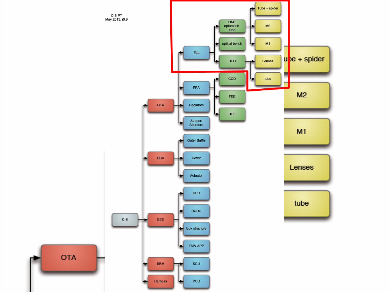
CHEOPS Product TreeCHEOPS Mission
CHEOPS Spacecraft
Launch VehicleCHEOPS
Ground Segment Instrument Assembly
System level AIT
Platform
Mission Operations
Science Operations
Data processing & Archiving
Baffle and Cover Assembly (BCA)
Optics Unit (OTA)
SEM
Harness CIS=CHEOPS Instrument System
CHEOPS Telescope WBS
CIS-601 TEL R. Ragazzoni
CIS-601.100 PMI. Pagano
CIS-601.200 SE. S. Scuderi
CIS-601.250 InterfacesJ. Farinato
CIS-601.300 PATBD
CIS-601.500 DesignR. Ragazzoni
CIS-601.510 OD & TolerancesD. Magrin
CIS-601.520 Opt. Mat. &Coat. TBD
CIS-601.530 Straylight Analysis M. Munari
CIS-601.600 DMV. Viotto
CIS-601.610 AIVV. Viotto
CIS-601.620 GSE M. Bergomi
CIS-601.800 PFM IT Prime
CIS-601.900 ProcurementR. Ragazzoni
CIS PayloadUBE
CIS-1 PMUBE
CIS-6 ProductUBE
CIS-60 OTA
CIS-601 TEL
CIS-604 STRUCT UBE
CIS-61 BCA
i0.9 May 2013
CHEOPS Milestones
CHEOPS TELESCOPE
Platform• Attitude Control
‣ 3-axis stabilized S/C - one side facing Earth
‣ pointing accuracy < 8 arc sec rms for 10h
• Instrument Power
‣ 50 W continuous power,
‣ 70 W peak
• Data rate
‣ 1 Gbit/day downlink
• Total mass with payload
‣ 200 kg
Payload - CIS
outer baffle
secondary mirror
primary mirror
structure (carbon fiber) baffle tower
focal plane assembly
beam shaper
radiators
DISCLAIMER • The following is just an outline of the expected
workload and boundary conditions of the Contract ASI will assign in the CHEOPS framework;
• All the following information are provisional and indicative;
• The detailed work description, its limits, and the responsibilities associated, will be available within the Call for Tender.
AIV plans
• Demonstration Model (DM) • Why: used to test TEL integration, alignment and verification (no
cryo-vacuum) procedures • When: starting from 2nd half of 2014 • Input: mechanical structure from UBE. Equivalent to STM, but
made with different material (CTE), i.e. thermally not equivalent. • Where: INAF-OAPD
• Other use: testing integration and alignment procedures for TEL+FPA
• Where: UBE
• GSE for DM reused for TEL PFM integration, alignment, and verification.
(cf . CHEOPS-INAF-MA-MIN-004)
DM GOALS
• To find and validate an alignment procedure giving a system compliant with requirements and tolerances
• TEL optics to Optical Bench (OB) alignment: • 500 µm • 400 µrad
• TEL optics internal alignment: • Optical quality (still TBD)
• Opto-mechanical interfaces verifications
• Identify tools useful for the AIV and verify no interferences arise
• At the moment the optical design is made in a way that: • The telescope mirrors relative alignment can be optimized (also in
focus) separately from the Back-End Optics. • The BEO can be internally aligned separately too.
DM CONCEPT
Ritchey-Chrétien internal alignment • A bearing rotation axis is
set as a reference: the TEL optical bench is mechanically aligned wrt the bearing with a dial gauge.
• The TEL mirrors are aligned one with respect to the other and to the rotation axis of the bearing.
• VERIFICATION: the TEL is fed with a beam realized with:
• Zygo interferometer • Beam expander • Flat mirror on a 45°
adjustable mount to explore the TEL FoV
TEL FoV
Bearing rotation
axis
GOALS: - focused image - symmetric quality on the FoV
- center of symm.: bearing rotation axis (reference is on a test camera)
Light exploring the FoV
BEO-to-telescope alignment
Exploring the FoV..
Test CCD#1
Test
CCD
#2
The Back-End Optics is internally aligned on the optical bench, separately from the rest of the TEL
TEL FoV
Bearing rotation
axis
The Back-End Optics is integrated and aligned to the Ritchey-Chrétien TEL. Quality along the FoV is then verified.
Verifications
ZYGO Interferometer + spherical element
1. TEL+BEO optical quality: tested in double-pass with ZYGO
1. Measurement of PSF size as a function of: • Position inside the FoV • Defocus • Wavelength (chromatism)
OAP
Fiber+mono chromator
Design Challenges
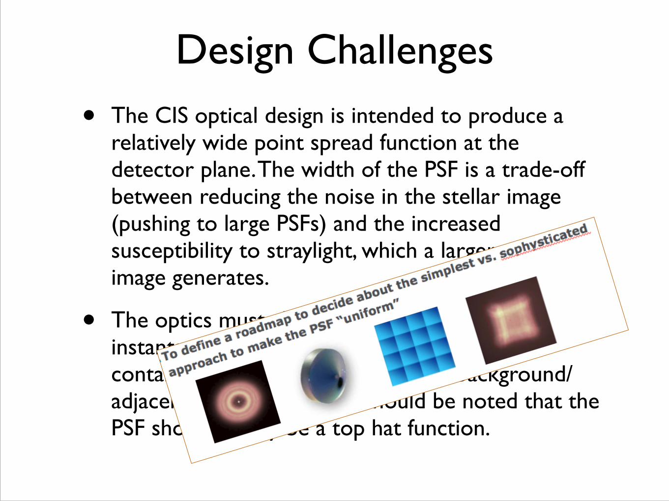
• The CIS optical design is intended to produce a relatively wide point spread function at the detector plane. The width of the PSF is a trade-off between reducing the noise in the stellar image (pushing to large PSFs) and the increased susceptibility to straylight, which a larger stellar image generates.
• The optics must also provide a sufficiently small instantaneous field of view (IFOV) to limit contamination of the signal through background/adjacent stellar sources. It should be noted that the PSF should ideally be a top hat function.
Design Challenges
• The optics are mounted in a structure of carbon-fibre reinforced polymer, which is used to reduce the susceptibility of the instrument to thermal variations which might be significant in near-Earth orbit.
• We are targeting an operational temperature of 250 K for the telescope structure.
• The change in distance between the primary and secondary mirrors (the parameter with the largest impact) should be within the ±<10 μm needed if the PSF is to be maintained constant to an appropriate level.
Design Challenges
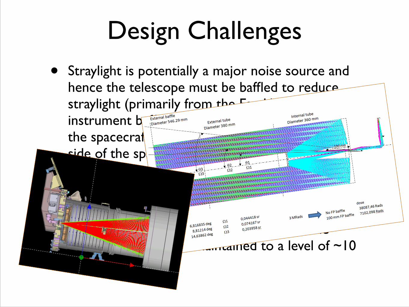
• Straylight is potentially a major noise source and hence the telescope must be baffled to reduce straylight (primarily from the Earth). The instrument baffling takes account of the rotation of the spacecraft, which maintains the Earth to one side of the spacecraft at all times. Concerns over cleanliness and contamination lead to introduction of a door cover (which is light and dust tight).
• The temperature stability of both the focal plane assembly and the electronics (to stabilize the system gain) must be maintained to a level of ~10 mK.
Design Challenges
• Straylight is potentially a major noise source and hence the telescope must be baffled to reduce straylight (primarily from the Earth). The instrument baffling takes account of the rotation of the spacecraft, which maintains the Earth to one side of the spacecraft at all times. Concerns over cleanliness and contamination lead to introduction of a door cover (which is light and dust tight).
• The temperature stability of both the focal plane assembly and the electronics (to stabilize the system gain) must be maintained to a level of ~10 mK.
Interfaces
• Great care is given to assess Interfaces where responsibilities can be clearly assigned.
• Ex.: Primary Mirror mounting:
Interfaces
• Great care is given to assess Interfaces where responsibilities can be clearly assigned.
• Ex.: Primary Mirror mounting:
Interfaces
• Great care is given to assess Interfaces where responsibilities can be clearly assigned.
• Ex.: Primary Mirror mounting:
Interfaces
• Great care is given to assess Interfaces where responsibilities can be clearly assigned.