26
University of Jordan Faculty of Engineering & Technology Computer Engineering Department Computer Networks Laboratory 907528 Lab 0: Introduction to Networks lab

University of Jordan
Faculty of Engineering & Technology
Computer Engineering Department
Computer Networks Laboratory
907528
Lab 0: Introduction to Networks lab
1 Lab 0: Introduction to Networks lab
Introduction to Networking
By themselves, computers are powerful tools. When they are connected in a network, they
become even more powerful because the functions and tools that each computer provides can
be shared with other computers.
Network is a small group of computers that share information, or they can be very complex,
spanning large geographical areas that provide its users with unique capabilities, above and
beyond what the individual machines and their software applications can provide.
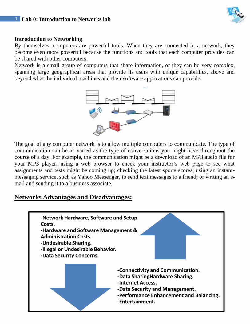
The goal of any computer network is to allow multiple computers to communicate. The type of
communication can be as varied as the type of conversations you might have throughout the
course of a day. For example, the communication might be a download of an MP3 audio file for
your MP3 player; using a web browser to check your instructor’s web page to see what
assignments and tests might be coming up; checking the latest sports scores; using an instant-
messaging service, such as Yahoo Messenger, to send text messages to a friend; or writing an e-
mail and sending it to a business associate.
Networks Advantages and Disadvantages:
-Network Hardware, Software and Setup Costs.-Hardware and Software Management & Administration Costs.-Undesirable Sharing.-Illegal or Undesirable Behavior.-Data Security Concerns.
-Connectivity and Communication.-Data SharingHardware Sharing.-Internet Access.-Data Security and Management.-Performance Enhancement and Balancing.-Entertainment.

2 Lab 0: Introduction to Networks lab
Network Types: Different types of networks are distinguished based on their size (in terms of the number of
machines), their data transfer speed, and their reach. There are usually said to be two categories
of networks:
Local Area Network (LAN)is limited to a specific area, usually an office, and cannot
extend beyond the boundaries of a single building. The first LANs were limited to a range
(from a central point to the most distant computer) of 185 meters (about 600 feet) and no more
than 30 computers. Today’s technology allows a larger LAN, but practical administration
limitations require dividing it into small, logical areas called workgroups.
A workgroup is a collection of individuals who share the same files and databases over the
LAN.
Wide Area Network (WAN)If you have ever connected to the Internet, you have used
the largest WAN on the planet. A WAN is any network that crosses metropolitan, regional, or
national boundaries. Most networking professionals define a WAN as any network that uses
routers and public network links. The Internet fits both definitions.
3 Lab 0: Introduction to Networks lab
The OSI and TCP/IP Networking Models: Models are useful because they help us understand difficult concepts and complicated systems.
When it comes to networking, there are several models that are used to explain the roles played
by various technologies, and how they interact. Of these, the most popular and commonly used
is the Open Systems Interconnection (OSI) Reference Model.
LAN WAN
Definition: LAN (Local Area Network) is a
computer network covering a
small geographic area, like a
home, office, schools, or group
of buildings.
WAN (Wide Area Network) is a
computer network that covers a
broad area or any network whose
communications links cross
metropolitan, regional, or national
boundaries over a long distance.
Speed: High speed(1000mbps) Less speed(150mbps)
Data transfer
rates:
High data transfer rate. Lower data transfer rate as
compared to LANs.
Example: Network in an organization. The Internet.
Components: Layer 2 devices like switches,
bridges. layer1 devices like
hubs , repeaters
Layers 3 devices Routers,
Switches and Technology specific
devices like ATM or Frame-relay
Switches.
Data Transmission
Error:
Experiences fewer data
transmission errors.
Experiences more data
transmission errors as compared to
LAN.
Ownership: Typically owned, controlled,
and managed by a single person
or organization.
WANs (like the Internet) are not
owned by any one organization
but rather exist under collective
distributed ownership and
management over long distances.
Set-up costs: Set-up an extra devices on the
network, it is not very
expensive.
Networks in remote areas have to
be connected, Set-up costs are
higher.
Maintenance costs: Covers a relatively small
geographical area, LAN is
easier to maintain at
relatively low costs.
Maintaining WAN is difficult
because of its wider geographical
coverage and higher maintenance
costs.
Geographical
Spread:
Have a
small geographical range.
Have a large geographical range
generally spreading across
boundaries.
Bandwidth: High bandwidth is available for
transmission.
Low bandwidth is available for
transmission.
4 Lab 0: Introduction to Networks lab
The OSI model was designed to promote interoperability by creating a guideline for network
data transmission between computers and components that have different hardware vendors,
software, operating systems, and protocols.
The idea behind the OSI Reference Model is to provide a framework for both designing
networking systems and for explaining how they work. The existence of the model makes it
easier for networks to be analyzed, designed, built and rearranged, by allowing them to be
considered as modular pieces that interact in predictable ways, rather than enormous, complex
monoliths.
TCP/IP Model
The Internet Protocol Suite, popularly known as the TCP/IP model, is a communication
protocol that is used over the Internet. This model divides the entire networking functions into
layers, where each layer performs a specific function.
This model gives a brief idea about the process of data formatting, transmission, and finally the
reception. Each of these functions takes place in the layers, as described by the model. TCP/IP
is a four-layered structure, with each layer having their individual protocol.

5 Lab 0: Introduction to Networks lab
Why Use a Layered Model?
By using a layered model, we can categorize the procedures that are necessary to transmit data
across a network. First, we need to define the term protocol: is a set of guidelines or rules of
communication.
Layered modeling allows us to:
• Create a protocol that can be designed and tested in stages, which, in turn, reduces the
complexity
• Enhance functionality of the protocol without adversely affecting the other layers
• Provide multivendor compatibility
• Allow for easier troubleshooting by locating the specific layer causing the problem
Both the TCP/IP and OSI model work in a very similar fashion. But they do have
very subtle differences too. The most apparent difference is the number of layers.
TCP/IP is a four-layered structure, while OSI is a seven-layered model.
6 Lab 0: Introduction to Networks lab
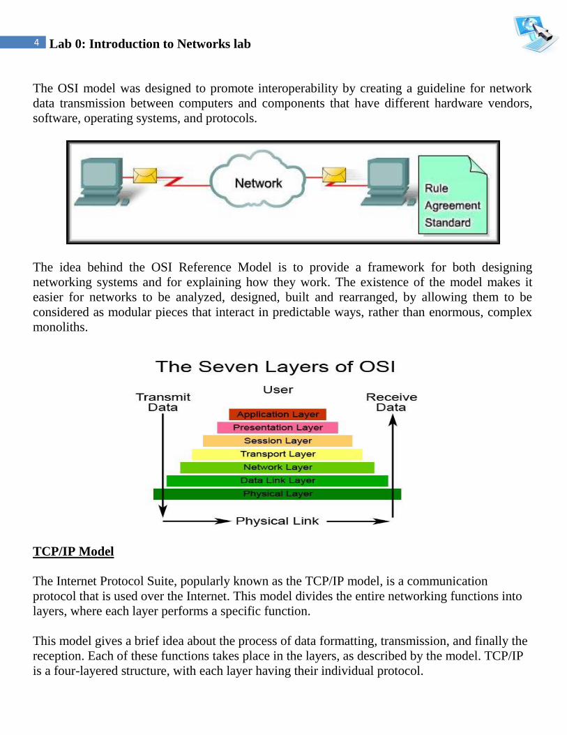
OSI model divides the network into seven layers and explains the routing of the data from
source to destination. It is a theoretical model which explains the working of the networks. Here
are the details of OSI's seven layers:
Application Layer (Layer 7)
The Application layer is a buffer between the user interface (what the user uses to perform
work) and the network application. This layer responsible for finding a communication partner
on the network. Once a partner is found, it is then responsible for ensuring that there is
sufficient network bandwidth to deliver the data.
This layer may also be responsible for synchronizing communication
and providing high level error checking between the two partners.
This ensures that the application is either sending or receiving, and
that the data transmitted is the same data received.
Typical applications include a client/server application (Telnet), an e-
mail application (SMTP), and an application to transfer files using
FTP or HTTP.
Presentation Layer (Layer 6)
The Presentation layer is responsible for the presentation of data to the Application layer. This
presentation may take the form of many structures. Data that it receives from the application
layer is converted into a suitable format that is recognized by the computer. Perform conversion
between ASCII and EBCDIC (a different character formatting method used on many
mainframes).
The Presentation layer must ensure that the application can view the appropriate data when it is
reassembled. Graphic files such as PICT, JPEG, TIFF, and GIF, and video and sound files such
as MPEG and Apple’s QuickTime are examples of Presentation layer responsibilities.
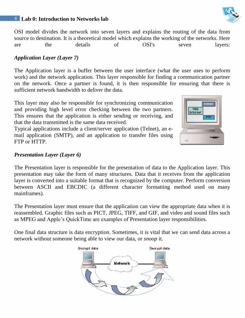
One final data structure is data encryption. Sometimes, it is vital that we can send data across a
network without someone being able to view our data, or snoop it.
7 Lab 0: Introduction to Networks lab
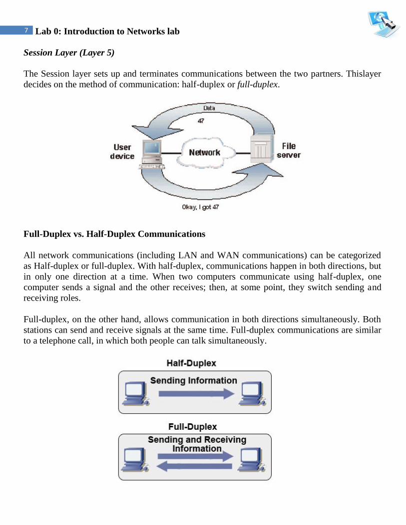
Session Layer (Layer 5)
The Session layer sets up and terminates communications between the two partners. Thislayer
decides on the method of communication: half-duplex or full-duplex.
Full-Duplex vs. Half-Duplex Communications
All network communications (including LAN and WAN communications) can be categorized
as Half-duplex or full-duplex. With half-duplex, communications happen in both directions, but
in only one direction at a time. When two computers communicate using half-duplex, one
computer sends a signal and the other receives; then, at some point, they switch sending and
receiving roles.
Full-duplex, on the other hand, allows communication in both directions simultaneously. Both
stations can send and receive signals at the same time. Full-duplex communications are similar
to a telephone call, in which both people can talk simultaneously.

8 Lab 0: Introduction to Networks lab
Transport Layer (Layer 4)
This layer provides end-to-end delivery of data between two nodes. It divides data into different
packets before transmitting it. On receipt of these packets, the data is reassembled and
forwarded to the next layer. If the data is lost in transmission or has errors, then this layer
recovers the lost data and transmits the same.
Transport layer add port number and sequence number to assemble and distinguish between
multiple applications segments received at a device; this also allows data to be multiplexed on
the line.
Multiplexing is the method of combining data from the upper layers and sending them through
the same data stream. This allows more than one application to communicate with the
communication partner at the same time. When the data reaches the remote partner, the
Transport layer then disassembles the segment and passes the correct data to each of the
receiving applications.
Network Layer (Layer 3)
The main function of this layer is routing data has to its intended destination on the network as
long as there is a physical network connection. The device that allows us to accomplish this
spectacular feat is the router, sometimes referred to as a Layer 3 device. While doing so, it has
to manage problems like network congestion, switching problems, etc.
In order for the router to succeed in this endeavor, it must be able to identify the source segment
and the final destination segment. This is done through network addresses, also called logical
addresses.
When a router receives data, it examines the Layer 3 data to determine the destination network
address. It then looks up the address in a table that tells it which route to use to get the data to
its final destination. It places the data on the proper connection, there by routing the packet
from one segment to another. The data may need to travel through many routers before
reaching its destination host. Each router in the path would perform the same lookup in its
table.

9 Lab 0: Introduction to Networks lab
Overview of IP Addresses
TCP/IP requires that each interface on a TCP/IP network have its own unique IP address. There
are two addressing schemes for TCP/IP: IPv4 and IPv6.
IPv4
An IPv4 address is a 32-bit number, usually represented as a four-part decimal number with
each of the four parts separated by a decimal point. In the IPv4 address, each individual byte, or
octet as it is sometimes called, can have a value in the range of 0 through 255.
The way these addresses are used varies according to the class of the network, so all you can
say with certainty is that the 32-bit IPv4 address is divided in some way to create an identifier
for the network, which all hosts on that network share, and an identifier for each host, which is
unique among all hosts on that network. In general, though, the higher-order bits of the address
make up the network part of the address and the rest constitutes the host part of the address. In
addition, the host part of the address can be divided further to allow for a sub network address.
IPv6
IPv6 was originally designed because the number of available unregistered IPv4 addresses was
running low. Because IPv6 uses a 128-bit addressing scheme, it has more than 79 octillion
times as many available addresses as IPv4. Also, instead of representing the binary digits as
decimal digits, IPv6 uses eight sets of four hexadecimal digits, like
so:3FFE:0B00:0800:0002:0000:0000:0000:000C.
Packets
At the Network layer, data coming from upper-layer protocols are divided into logical chunks
called packets. A packet is a unit of data transmission. The size and format of these packets
depend on the Network layer protocol in use. In other words, IP packets differ greatly from IPX
packets and Apple-Talk DDP packets, and the three are not compatible.

10 Lab 0: Introduction to Networks lab
Data Link Layer (Layer 2)
The main function of this layer is to convert the data packets received from the upper layer into
frames, and route the same to the physical layer. Error detection and correction is done at this
layer, thus making it a reliable layer in the model. It establishes a logical link between the nodes
and transmits frames sequentially.
The Data Link layer is split into two sub layers, the Logical Link Control (LLC) and the Media
Access Control (MAC). MAC sub layer is closer to the Physical layer.
The MAC sub layer defines a physical address, called a MAC address or hardware address,
which is unique to each individual network interface. This allows a way to uniquely identify
each network interface on a network, even if the network interfaces are on the same computer.
More importantly, though, the MAC address can be used in any network that supports the
chosen network interface.

11 Lab 0: Introduction to Networks lab
MAC layer on the receiving computer will take the bits from the Physical layer and put them in
order into a frame. It will also do a CRC (Cyclic Redundancy Check) to determine if there are
any errors in the frame.
It will check the destination hardware address to determine if the data is meant for it, or if it
should be dropped or sent on to the next machine. If the data is meant for the current computer,
it will pass it to the LLC layer.
The LLC layer is the buffer between the software protocols and the hardware protocols. It is
responsible for taking the data from the Network layer and sending it to the MAC layer. This
allows the software protocols to run on any type of network architecture.
What Is a MAC Address?
The MAC address is a unique value associated with a network adapter. MAC addresses
are also known as hardware addresses or physical addresses. They uniquely identify an
adapter on a LAN.
MAC addresses are 12-digit hexadecimal numbers (48 bits in length). By convention,
MAC addresses are usually written as the following format:
MM:MM:MM:SS:SS:SS or MM-MM-MM-SS-SS-SS
The first half of a MAC address contains the ID number of the adapter manufacturer.
These IDs are regulated by an Internet standards body (see sidebar). The second half of a
MAC address represents the serial number assigned to the adapter by the manufacturer.
MAC addresses function at the data link layer (layer 2). They allow computers to
uniquely identify themselves on a network at this relatively low level.

12 Lab 0: Introduction to Networks lab
Frames
At the Data Link layer, data coming from upper-layer protocols are divided into logical chunks
called frames. A frame is a unit of data transmission. The size and format of these frames
depend on the transmission technology. In other words, Ethernet frames differ greatly from
Token Ring frames and Frame Relay frames, and the three are not compatible.
Physical Layer (Layer 1)
As the name suggests, this is the layer where the physical connection between two computers
takes place. The data is transmitted via this physical medium to the destination's physical layer.
It is responsible for sending data and receiving data across a physical medium.
This data is sent in bits, either a 0 or a 1. The data may be transmitted as electrical signals (that
is, positive and negative voltages), audio tones, or light.
This layer also defines the Data Terminal Equipment (DTE) and the Data Circuit-Terminating
Equipment (DCE). The DTE is often accessed through a modem or a Channel Service
Unit/Data Service Unit (CSU/DSU) connected to a PC or a router. The carrier of the WAN
signal provides the DCE equipment. A typical device would be a packet switch, which is
responsible for clocking and switching.
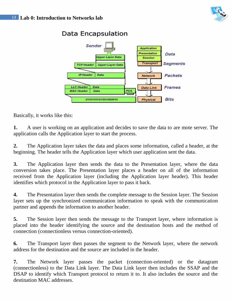
Data Encapsulation Using the OSI Model
Since there may be more than one application using more than one communication partner
using more than one protocol, how does the data get to its destination correctly. This is
accomplished through a process called data encapsulation.
13 Lab 0: Introduction to Networks lab
Basically, it works like this:
1. A user is working on an application and decides to save the data to are mote server. The
application calls the Application layer to start the process.
2. The Application layer takes the data and places some information, called a header, at the
beginning. The header tells the Application layer which user application sent the data.
3. The Application layer then sends the data to the Presentation layer, where the data
conversion takes place. The Presentation layer places a header on all of the information
received from the Application layer (including the Application layer header). This header
identifies which protocol in the Application layer to pass it back.
4. The Presentation layer then sends the complete message to the Session layer. The Session
layer sets up the synchronized communication information to speak with the communication
partner and appends the information to another header.
5. The Session layer then sends the message to the Transport layer, where information is
placed into the header identifying the source and the destination hosts and the method of
connection (connectionless versus connection-oriented).
6. The Transport layer then passes the segment to the Network layer, where the network
address for the destination and the source are included in the header.
7. The Network layer passes the packet (connection-oriented) or the datagram
(connectionless) to the Data Link layer. The Data Link layer then includes the SSAP and the
DSAP to identify which Transport protocol to return it to. It also includes the source and the
destination MAC addresses.
14 Lab 0: Introduction to Networks lab
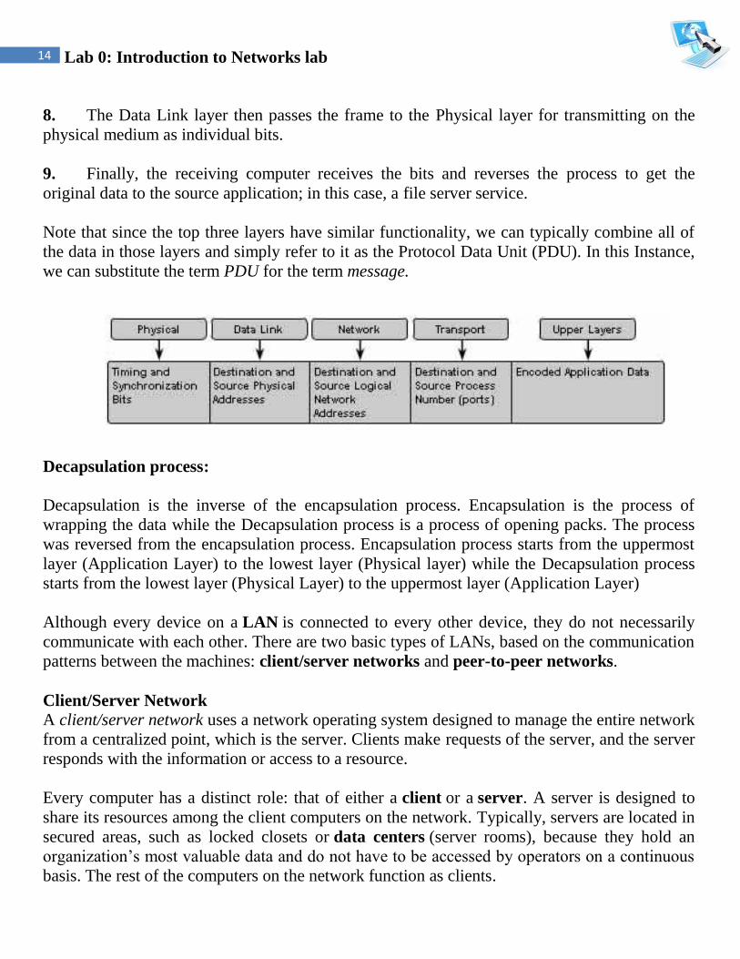
8. The Data Link layer then passes the frame to the Physical layer for transmitting on the
physical medium as individual bits.
9. Finally, the receiving computer receives the bits and reverses the process to get the
original data to the source application; in this case, a file server service.
Note that since the top three layers have similar functionality, we can typically combine all of
the data in those layers and simply refer to it as the Protocol Data Unit (PDU). In this Instance,
we can substitute the term PDU for the term message.
Decapsulation process:
Decapsulation is the inverse of the encapsulation process. Encapsulation is the process of
wrapping the data while the Decapsulation process is a process of opening packs. The process
was reversed from the encapsulation process. Encapsulation process starts from the uppermost
layer (Application Layer) to the lowest layer (Physical layer) while the Decapsulation process
starts from the lowest layer (Physical Layer) to the uppermost layer (Application Layer)
Although every device on a LAN is connected to every other device, they do not necessarily
communicate with each other. There are two basic types of LANs, based on the communication
patterns between the machines: client/server networks and peer-to-peer networks.
Client/Server Network
A client/server network uses a network operating system designed to manage the entire network
from a centralized point, which is the server. Clients make requests of the server, and the server
responds with the information or access to a resource.
Every computer has a distinct role: that of either a client or a server. A server is designed to
share its resources among the client computers on the network. Typically, servers are located in
secured areas, such as locked closets or data centers (server rooms), because they hold an
organization’s most valuable data and do not have to be accessed by operators on a continuous
basis. The rest of the computers on the network function as clients.

15 Lab 0: Introduction to Networks lab
Peer-to-Peer Network
In peer-to-peer networks, the connected computers have no centralized authority. From an
authority viewpoint, all of these computers are equal. In other words, they are peers. If a user of
one computer wants access to a resource on another computer, the security check for access
rights is the responsibility of the computer holding the resource.
Each computer in a peer-to-peer network can be both a client that requests resources and a
server that provides resources.
Application Layer Services and Protocols
Understanding Servers In the truest sense, a server does exactly what the name implies: It provides resources to the
clients on the network (“serves” them, in other words). Servers are typically powerful
computers that run the software that controls and maintains.
16 Lab 0: Introduction to Networks lab
Servers are often specialized for a single purpose. This is not to say that a single server can’t do
many jobs, but you’ll get better performance if you dedicate a server to a single task. Here are
some examples of servers that are dedicated to a single task:
File Server Holds and distributes files.
Print Server Controls and manages one or more printers for the network.
Proxy Server Performs a function on behalf of other computers.
Application Server Hosts a network application.
Web Server Holds and delivers web pages and other web content using the Hypertext
Transfer Protocol (HTTP).
Mail Server Hosts and delivers e-mail. It’s the electronic equivalent of a post office.
Fax Server Sends and receives faxes for the entire network without the need for paper.
Telephony Server Functions as a “smart” answering machine for the network. It can
also perform call center and call-routing functions.
Notice that each server type’s name consists of the type of service the server provides
(remote access, for example) followed by the word server, which, as you remember, means to
serve.
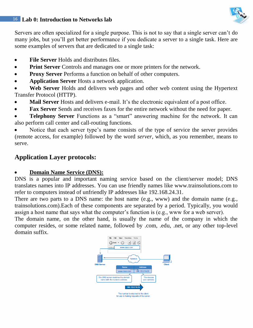
Application Layer protocols: Domain Name Service (DNS): DNS is a popular and important naming service based on the client/server model; DNS
translates names into IP addresses. You can use friendly names like www.trainsolutions.com to
refer to computers instead of unfriendly IP addresses like 192.168.24.31.
There are two parts to a DNS name: the host name (e.g., www) and the domain name (e.g.,
trainsolutions.com).Each of these components are separated by a period. Typically, you would
assign a host name that says what the computer’s function is (e.g., www for a web server).
The domain name, on the other hand, is usually the name of the company in which the
computer resides, or some related name, followed by .com, .edu, .net, or any other top-level
domain suffix.

17 Lab 0: Introduction to Networks lab
Dynamic Host Configuration Protocol (DHCP):
DHCP used to provide IP configuration information to hosts on boot up. DHCP manages
addressing by leasing the IP information to the hosts. This leasing allows the information to be
recovered when not in use and reallocated when needed.
The primary reason for using DHCP is to centralize the management of IP addresses. When the
DHCP service is used, DHCP scopes include pools of IP addresses that are assigned for
automatic distribution to client computers on an as-needed basis, in the form of leases, which
are periods of time for which the DHCP client may keep the configuration assignment. Clients
attempt to renew their lease at 50 percent of the lease duration. The address pools are
centralized on the DHCP server, allowing all IP addresses on your network to be administered
from a single server.
It should be apparent that this saves loads of time when changing the IP addresses on your
network. Instead of running around to every workstation and server and resetting the IP address
to a new address, you simply reset the IP address pool on the DHCP server. The next time the
client machines are rebooted, they are assigned new addresses.
DHCP Information can include:
• IP address.
• Subnet mask.
• Default gateway.
• Domain name.
• DNS Server.
Simple Network Management Protocol (SNMP):
SNMP allows network administrators to collect information about the network. It is a
communications protocol for collecting information about devices on the network, including
hubs, routers, and bridges. Each piece of information to be collected about a device is defined
in a Management Information Base (MIB). SNMP uses UDP to send and receive messages on
the network.

18 Lab 0: Introduction to Networks lab
File Transfer Protocol (FTP):
FTP provides a mechanism for single or multiple file transfers between computer systems;
when written in lowercase as “ftp,” it is also the name of the client software used to access the
FTP server running on the remote host. The FTP package provides all the tools needed to look
at files and directories, change to other directories, and transfer text and binary files from one
system to another. FTP uses TCP to actually move the files.
Trivial File Transfer Protocol (TFTP):
TFTP is a “stripped down” version of FTP, primarily used to boot diskless workstations and to
transfer boot images to and from routers. It uses a reduced feature set (fewer commands and a
smaller overall program size). In addition to its reduced size, it also uses UDP instead of TCP,
which makes for faster transfers but with no reliability.
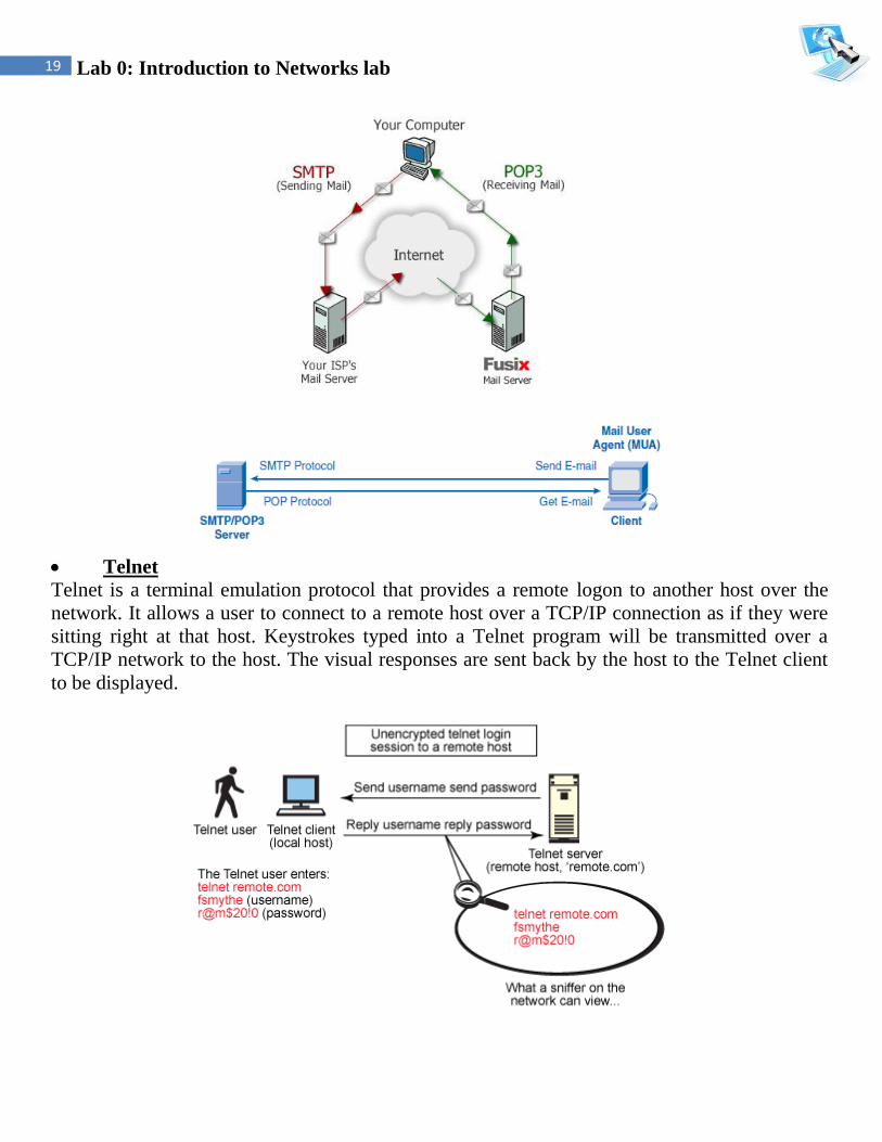
Simple Mail Transfer Protocol (SMTP):
SMTP allows for a simple e-mail service and is responsible for moving messages from one e-
mail server to another.
Post Office Protocol (POP):
POP provides a storage mechanism for incoming mail; the latest version of the standard is
known as POP3. When a client connects to a POP3 server, all the messages addressed to that
client are downloaded; there is no way to download messages selectively. Once the messages
are downloaded, the user can delete or modify messages without further interaction with the
server. In some locations, POP3 is being replaced by another standard, IMAP.
FTP Client
FTP Server
FTP Client FTP Server
19 Lab 0: Introduction to Networks lab
Telnet
Telnet is a terminal emulation protocol that provides a remote logon to another host over the
network. It allows a user to connect to a remote host over a TCP/IP connection as if they were
sitting right at that host. Keystrokes typed into a Telnet program will be transmitted over a
TCP/IP network to the host. The visual responses are sent back by the host to the Telnet client
to be displayed.
20 Lab 0: Introduction to Networks lab
Secure Shell (SSH):
SSH used to establish a secure Telnet session over a standard TCP/ IP connection. It is used to
run programs on remote systems, log in to other systems, and move files from one system to
another, all while maintaining a strong, encrypted connection.
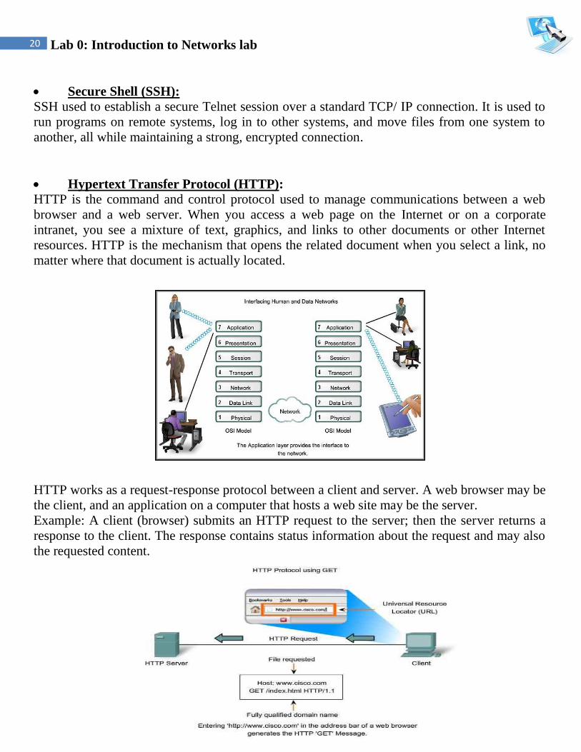
Hypertext Transfer Protocol (HTTP):
HTTP is the command and control protocol used to manage communications between a web
browser and a web server. When you access a web page on the Internet or on a corporate
intranet, you see a mixture of text, graphics, and links to other documents or other Internet
resources. HTTP is the mechanism that opens the related document when you select a link, no
matter where that document is actually located.
HTTP works as a request-response protocol between a client and server. A web browser may be
the client, and an application on a computer that hosts a web site may be the server.
Example: A client (browser) submits an HTTP request to the server; then the server returns a
response to the client. The response contains status information about the request and may also
the requested content.
21 Lab 0: Introduction to Networks lab
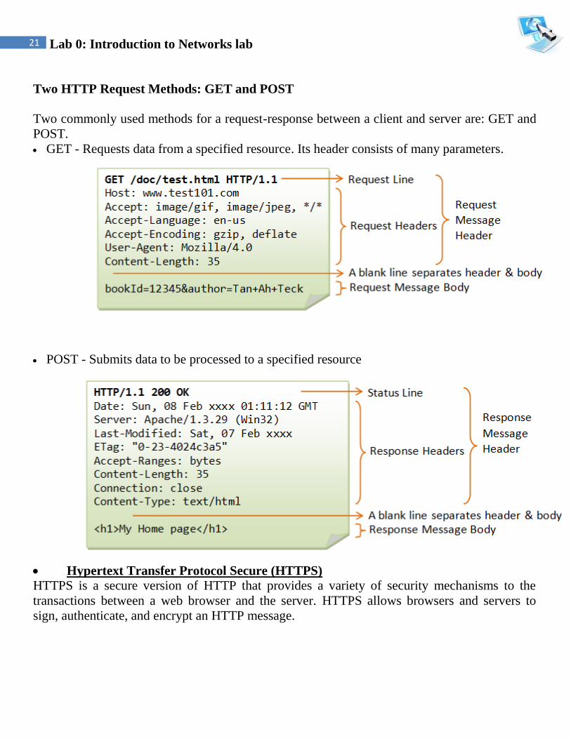
Two HTTP Request Methods: GET and POST
Two commonly used methods for a request-response between a client and server are: GET and
POST.
GET - Requests data from a specified resource. Its header consists of many parameters.
POST - Submits data to be processed to a specified resource
Hypertext Transfer Protocol Secure (HTTPS) HTTPS is a secure version of HTTP that provides a variety of security mechanisms to the
transactions between a web browser and the server. HTTPS allows browsers and servers to
sign, authenticate, and encrypt an HTTP message.

22 Lab 0: Introduction to Networks lab
Transport layer protocols (TCP/UDP)
TCP stands for Transmission Control Protocol, and UDP is the abbreviation for User Datagram
Protocol. Both pertain to data transmissions on the Internet, but they work very differently.
TCP UDP
Acronym for: Transmission Control Protocol User Datagram Protocol
Function: As a message makes its way
across the internet from one
computer to another. This is
connection based.
UDP is also a protocol used in
message transport or transfer. This is
not connection based.
Usage: TCP is used in case of non-time
critical applications.
UDP is used for games or applications
that require fast transmission of data.
Examples: HTTP, HTTPs, FTP, SMTP
Telnet etc...
DNS, DHCP, TFTP, SNMP, RIP,
VOIP etc...
Ordering of data
packets:
TCP rearranges data packets
in the order specified.
UDP has no order as all packets are
independent of each other. If ordering
is required, it has to be managed by
the application layer.
Speed of transfer: The speed for TCP is slower than
UDP.
UDP is faster because there is no
error-checking for packets.
Reliability: There is absolute guarantee that
the data transferred remains
intact and arrives in the same
order in which it was sent.
There is no guarantee that the
messages or packets sent would reach
at all.
Header Size: TCP header size is 20 bytes UDP Header size is 8 bytes.
Streaming of data: Data is read as a byte stream,
no indications are transmitted to
signal message(segment)
boundaries.
Packets sent and checked individually
for integrity only if they arrive.
Packets have definite boundaries
which are honored uponreceipt.
Data Flow Control: TCP does Flow Control, handles
reliability and congestion
control.
UDP does not have an option forflow
control
Error Checking: TCP does error checking UDP does error checking, but no
recovery options.
Acknowledgement: Acknowledgement segments No Acknowledgment

23 Lab 0: Introduction to Networks lab
Port number
A port number is a way to identify a specific process to which an Internet or other network
message is to be forwarded when it arrives at a server. For the Transmission Control Protocol
and the User Datagram Protocol, a port number is a 16-bit integer that is put in the header
appended to a message unit. This port number is passed logically between client and server
transport layers and physically between the transport layer and the Internet Protocol layer and
forwarded on.
For example, a request from a client (perhaps on behalf of you at your PC) to a server on the
Internet may request a file be served from that host's File Transfer Protocol (FTP) server or
process. In order to pass your request to the FTP process in the remote server, the Transmission
Control Protocol (TCP) software layer in your computer identifies the port number of 21
(which by convention is associated with an FTP request) in the 16-bit port number integer that
is appended to your request. At the server, the TCP layer will read the port number of 21 and
forward your request to the FTP program at the server.
Port Range Groups
0 to 1023 - Well known port numbers: Reserved for common services and applications.
1024 to 49151 - Registered ports; meaning they can be registered to specific protocols
by software corporations.
49152 to 65536 - Dynamic or private ports; usually assigned dynamically to client
applications initiating a connection.
Port
Number
Application Layer 4
Protocol
Description
20 FTP TCP File Transfer Protocol – Data
21 FTP TCP File Transfer Protocol – Control Commands
23 TELNET TCP Terminal connection
25 SMTP TCP Simple Mail Transfer Protocol - Email
53 DNS UDP Domain Name System
67,68 DHCP UDP Dynamic Host Configuration Protocol
69 TFTP UDP Trivial File Transfer Protocol
80 HTTP TCP Hypertext Transfer Protocol

24 Lab 0: Introduction to Networks lab
Commutation message types:
Unicast
Unicast packets are sent from host to host. The communication is from a single host to another
single host. There is one device transmitting a message destined for one receiver.
Broadcast
Broadcast is when a single device is transmitting a message to all other devices in a given
address range. This broadcast could reach all hosts on the subnet, all subnets, or all hosts on all
subnets. Broadcast packets have the host (and/or subnet) portion of the address set to all ones.
By design, most modern routers will block IP broadcast traffic and restrict it to the local subnet.
Multicast
Multicast is a special protocol for use with IP. Multicast enables a single device to
communicate with a specific set of hosts, not defined by any standard IP address and mask
combination. This allows for communication that resembles a conference call. Anyone from
anywhere can join the conference, and everyone at the conference hears what the speaker has to
say. The speaker's message isn't broadcasted everywhere, but only to those in the conference
call itself. A special set of addresses is used for multicast communication.
25 Lab 0: Introduction to Networks lab
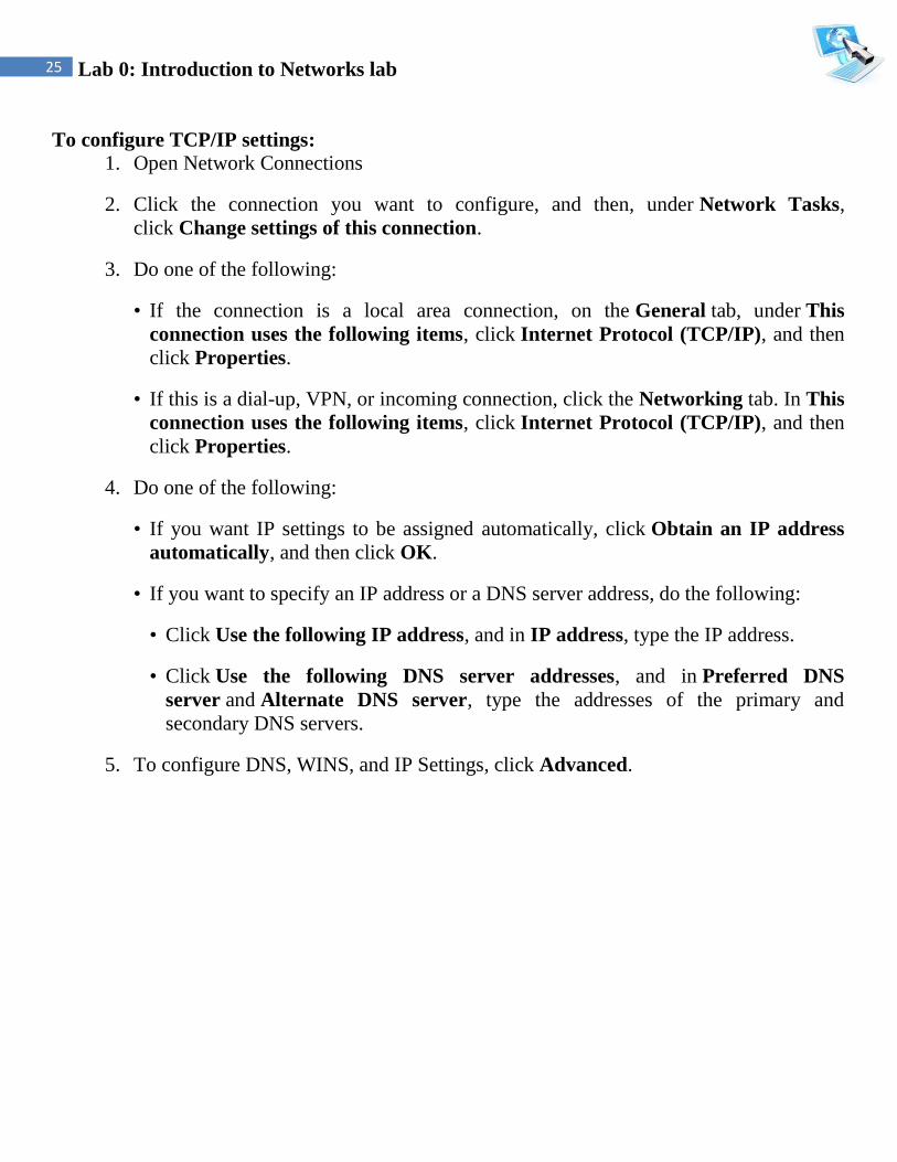
To configure TCP/IP settings:
1. Open Network Connections
2. Click the connection you want to configure, and then, under Network Tasks,
click Change settings of this connection.
3. Do one of the following:
• If the connection is a local area connection, on the General tab, under This
connection uses the following items, click Internet Protocol (TCP/IP), and then
click Properties.
• If this is a dial-up, VPN, or incoming connection, click the Networking tab. In This
connection uses the following items, click Internet Protocol (TCP/IP), and then
click Properties.
4. Do one of the following:
• If you want IP settings to be assigned automatically, click Obtain an IP address
automatically, and then click OK.
• If you want to specify an IP address or a DNS server address, do the following:
• Click Use the following IP address, and in IP address, type the IP address.
• Click Use the following DNS server addresses, and in Preferred DNS
server and Alternate DNS server, type the addresses of the primary and
secondary DNS servers.
5. To configure DNS, WINS, and IP Settings, click Advanced.


