Page 1
1300 Henley Court Pullman, WA 99163
509.334.6306 www.store.digilentinc.com
Lab 2b: Dynamic Stepper Motor Control
Revised May 23, 2017 This manual applies to Unit 2, Lab 2b
Unit 2, Lab 2b Copyright Digilent, Inc. All rights reserved. Other product and company names mentioned may be trademarks of their respective owners. Page 1 of 16
1 Objectives
1. Develop an application of foreground-background task scheduling.
2. Use change notification interrupts to detect push button presses and releases.
3. Eliminate multiple button operations using a timer interrupt to implement a non-blocking delay.
2 Basic Knowledge
1. Understanding of combinational logic and sequential logic.
2. Using the SWITCH-CASE construct in C.
3. How to interpret a schematic diagram and electric circuits.
4. Fundamentals of stepper motors.
3 Equipment List
3.1 Hardware
1. Basys MX3 trainer board
2. Micro USB cable
3. Workstation computer running Windows 10 or higher, MAC OS, or Linux
4. 4 wire stepper motor
5. 5V, 4A DC power supply
In addition, we suggest the following instruments:
6. Digilent Analog Discovery 2
3.2 Software
1. Microchip MPLAB X® v3.35 or higher
2. XC32 Cross Compiler
3. PLIB Peripheral Library
4. WaveForms 2015
Page 2
Lab 2b: Dynamic Stepper Motor Control
Copyright Digilent, Inc. All rights reserved. Other product and company names mentioned may be trademarks of their respective owners. Page 2 of 16
4 Project Takeaways
1. The ability to control the speed of rotation of a stepper motor.
2. Determine the number of steps required for one rotation of the rotor.
3. How to determine the delay time between steps, resulting in a specified rotation speed.
5 Fundamental Concepts
After a search of the internet, one will find that the stepper motor is one of the most frequently used examples of
an application of finite state machines (FSM). Applications that use stepper motors include robotics, disk drives,
and office products like laser printers and copiers.
6 Problem Statement
Use the eight slide switches to set the speed of rotation of the stepper motor shaft from 0 to 31.875 RPM in steps
of 0.125 RPM. BTND will switch the motor operation from FULL step to HALF step when depressed. BTNR will
switch the rotational direction of the rotor from CW to CCW when pressed. The speed of rotation will be displayed
on the four-digit seven-segment display digits with 25% duty cycle persistence and one ms update rate.
7 Background Information
Stepper motors are electrical mechanical devices used in many robotics applications. In this lab, we will look at
how the PIC32 internal timers can be used to implement both cooperative and preemptive scheduling for a real-
time system application. We will use time management to transition between states, giving the appearance of
continuous rotation of the motor. The position of the stepper motor shaft is a function of four outputs. These
outputs must change in a predefined order to cause the motor shaft to move in discrete steps. The outputs to the
stepper motor are controlled using a state machine algorithm that generates output patterns and will be used to
control position and angular velocity.
Since the PIC32 outputs represent a form of memory, I find it convenient to use state on-entry or on-exit actions to
set the processor pins. An on-entry action sets the phase outputs specified for that case whenever a state (case) is
entered. An on-exit action sets the phase outputs specified for that case whenever a next state (case) is set. The
DIR and MODE inputs define the next state using “if-else” or a sub level of “switch-case” statements.
An alternate implementation uses a table of output codes and an index that becomes the state. It must be
remembered that the Basys MX3 platform does not connect consecutive processor pins on a single port to the
stepper motor phases. Hence, the state output table must be replaced with a sequence of bit-banging instructions
to individually set each phase output pin.
Page 3
Lab 2b: Dynamic Stepper Motor Control
Copyright Digilent, Inc. All rights reserved. Other product and company names mentioned may be trademarks of their respective owners. Page 3 of 16
8 Lab 2b
8.1 Requirements
1. This make of stepper motor is nominally rated for 1600 steps per revolution +/- 7%. Hence, the range can
be from 1488 to 1712 steps per revolution. Determine the number of steps for one complete revolution
for the particular motor you are using.
2. BTNR controls the direction of rotor rotation (CW or CCW).
3. BTND controls the stepper motor step mode (full or half step).
a. The speed or rotation must be the same regardless of stepper mode operation.
4. The speed of rotation is set by the hexadecimal value set on the eight slide switches. SW7 is the most
significant bit and SW0 is the least significant bit with the switch weighting, as shown in Table 8.1.
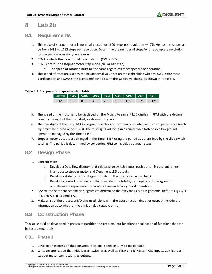
Table 8.1. Stepper motor speed control table.
Switch SW7 SW6 SW5 SW4 SW3 SW2 SW1 SW0
RPM 16 8 4 2 1 0.5 0.25 0.125
5. The speed of the motor is to be displayed on the 4-digit 7-segment LED display in RPM with the decimal
point to the right of the third digit, as shown in Fig. A.2.
6. The four digits of the Basys MX3 7-segment display are continually updated with a 1 ms persistence (each
digit must be turned on for 1 ms). The four digits will be lit in a round-robin fashion in a foreground
operation managed by the Timer 1 ISR.
7. Stepper motor outputs are changed in the Timer 1 ISR using the period as determined by the slide switch
settings. The period is determined by converting RPM to ms delay between steps.
8.2 Design Phase
1. Concept maps
a. Develop a Data flow diagram that relates slide switch inputs, push button inputs, and timer
interrupts to stepper motor and 7-segment LED outputs.
b. Develop a state transition diagram similar to the one described in Unit 2.
c. Develop a control flow diagram that describes the total system operation. Background
operations are represented separately from each foreground operation.
2. Review the pertinent schematic diagrams to determine the relevant IO pin assignments. Refer to Figs. A.3,
A.4, and A.5 in Appendix A.
3. Make a list of the processor I/O pins used, along with the data direction (input or output). Include the
information as to whether the pin is analog capable or not.
8.3 Construction Phase
This lab should be developed in phases to partition the problem into functions or collection of functions that can
be tested separately.
8.3.1 Phase 1
1. Develop an expression that converts rotational speed in RPM to ms per step.
2. Write an application that initializes all switches as well as BTNR and BTND as PIC32 inputs. Configure all
stepper motor connections as outputs.
Page 4
Lab 2b: Dynamic Stepper Motor Control
Copyright Digilent, Inc. All rights reserved. Other product and company names mentioned may be trademarks of their respective owners. Page 4 of 16
3. Develop a PIC32 application program that causes the stepper motor to take a single step in a specified
direction (CW or CCW) in a specified mode (half or full step).
4. The rotational direction of the stepper is such that when BTNR is depressed, the motor rotates in a
clockwise (CW) direction, otherwise it rotates in a counterclockwise (CCW) direction.
5. This program will be operated with a breakpoint set in the infinite loop function to determine if the
stepper motor phase connection is correct.
6. Using a software delay, determine the number of steps needed for one complete revolution. (See
Requirement 1 above.)
8.3.2 Phase 2
1. Initialize Timer 1 to generate a Level 2 interrupt once each 1/10 millisecond.
2. Write a Timer 1 interrupt service routine that causes the 7-segment LED to display the RPM (in decimal
values) set by the binary encoded switch settings. The LED display is to update one of the four digits once
each millisecond.
8.3.3 Phase 3
1. Integrate Phase 1 and Phase 2 to implement the following controls in steps two and three.
2. The speed of the stepper motor in revolutions per minute (RPM) is set by the binary encoding of the eight
slide switch positions. For example, the position of the slide switches shown in Fig. A.1 results in the
stepper motor rotating at 60 RPM. 60 RPM results when SW5, SW4, SW3, and SW2 are set high.
3. The stepper motor normally operates using half steps. If BTND is held depressed, the stepper motor
switches to full step operation without altering the RPM set by the slide switches and returns to half step
upon release of the button.
8.4 Testing
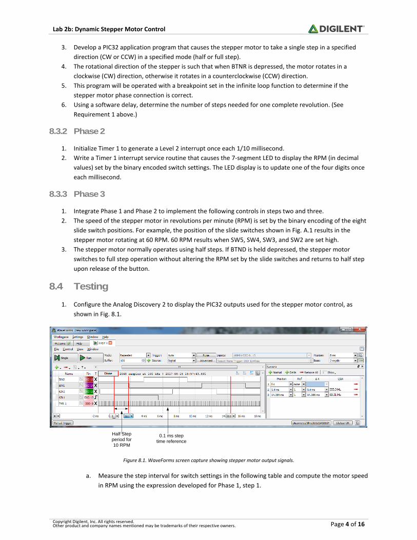
1. Configure the Analog Discovery 2 to display the PIC32 outputs used for the stepper motor control, as
shown in Fig. 8.1.
Half Step
period for
10 RPM
0.1 ms step
time reference
Figure 8.1. WaveForms screen capture showing stepper motor output signals.
a. Measure the step interval for switch settings in the following table and compute the motor speed
in RPM using the expression developed for Phase 1, step 1.
Page 5
Lab 2b: Dynamic Stepper Motor Control
Copyright Digilent, Inc. All rights reserved. Other product and company names mentioned may be trademarks of their respective owners. Page 5 of 16
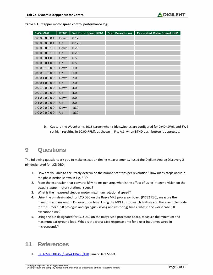
Table 8.1. Stepper motor speed control performance log.
SW7-SW0 BTND Set Rotor Speed RPM Step Period – ms Calculated Rotor Speed RPM
0 0 0 0 0 0 0 1 Down 0.125
0 0 0 0 0 0 0 1 Up 0.125
0 0 0 0 0 0 1 0 Down 0.25
0 0 0 0 0 0 1 0 Up 0.25
0 0 0 0 0 1 0 0 Down 0.5
0 0 0 0 0 1 0 0 Up 0.5
0 0 0 0 1 0 0 0 Down 1.0
0 0 0 0 1 0 0 0 Up 1.0
0 0 0 1 0 0 0 0 Down 2.0
0 0 0 1 0 0 0 0 Up 2.0
0 0 1 0 0 0 0 0 Down 4.0
0 0 1 0 0 0 0 0 Up 4.0
0 1 0 0 0 0 0 0 Down 8.0
0 1 0 0 0 0 0 0 Up 8.0
1 0 0 0 0 0 0 0 Down 16.0
1 0 0 0 0 0 0 0 Up 16.0
b. Capture the WaveForms 2015 screen when slide switches are configured for 0x40 (SW6, and SW4
set high resulting in 10.00 RPM), as shown in Fig. A.1, when BTND push button is depressed.
9 Questions
The following questions ask you to make execution timing measurements. I used the Digilent Analog Discovery 2
pin designated for LCD DB0.
1. How are you able to accurately determine the number of steps per revolution? How many steps occur in
the phase period shown in Fig. 8.1?
2. From the expression that converts RPM to ms per step, what is the effect of using integer division on the
actual stepper motor rotational speed?
3. What is the measured stepper motor maximum rotational speed?
4. Using the pin designated for LCD DB0 on the Basys MX3 processor board (PIC32 RE0), measure the
minimum and maximum ISR execution time. Using the MPLAB stopwatch feature and the assembler code
for the Timer 1 ISR prologue and epilogue (saving and restoring) times, what is the worst case ISR
execution time?
5. Using the pin designated for LCD DB0 on the Basys MX3 processor board, measure the minimum and
maximum background loop. What is the worst case response time for a user input measured in
microseconds?
11 References
1. PIC32MX330/350/370/430/450/470 Family Data Sheet.
Page 6
Lab 2b: Dynamic Stepper Motor Control
Copyright Digilent, Inc. All rights reserved. Other product and company names mentioned may be trademarks of their respective owners. Page 6 of 16
2. Basys MX3 Reference Manual.
3. How Stepper Motors Work, https://www.youtube.com/watch?v=bngx2dKl5jU.
4. MPLAB X Stopwatch, https://learn.digilentinc.com/Documents/211.
Page 7
Lab 2b: Dynamic Stepper Motor Control
Copyright Digilent, Inc. All rights reserved. Other product and company names mentioned may be trademarks of their respective owners. Page 7 of 16
Appendix A: Basys MX3 Schematic Drawings and
Equipment Configurations
Figure A.1. Equipment configuration for Lab 2b.
Page 8
Lab 2b: Dynamic Stepper Motor Control
Copyright Digilent, Inc. All rights reserved. Other product and company names mentioned may be trademarks of their respective owners. Page 8 of 16
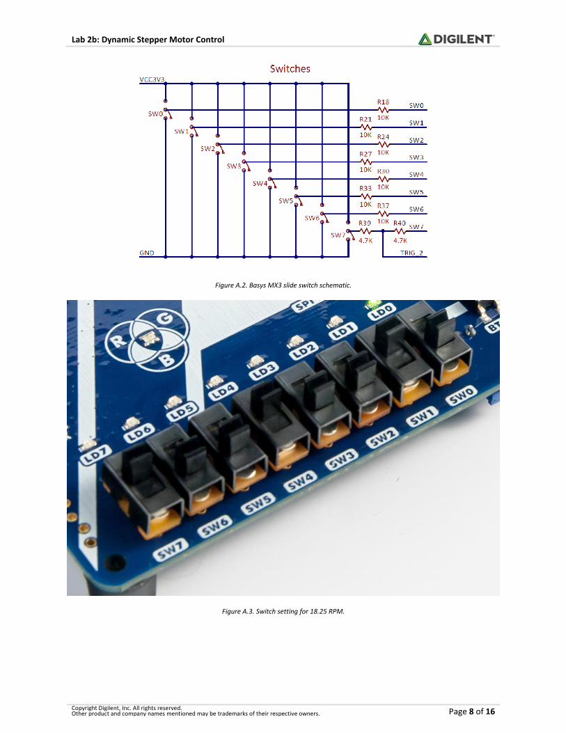
Figure A.2. Basys MX3 slide switch schematic.
Figure A.3. Switch setting for 18.25 RPM.
Page 9
Lab 2b: Dynamic Stepper Motor Control
Copyright Digilent, Inc. All rights reserved. Other product and company names mentioned may be trademarks of their respective owners. Page 9 of 16
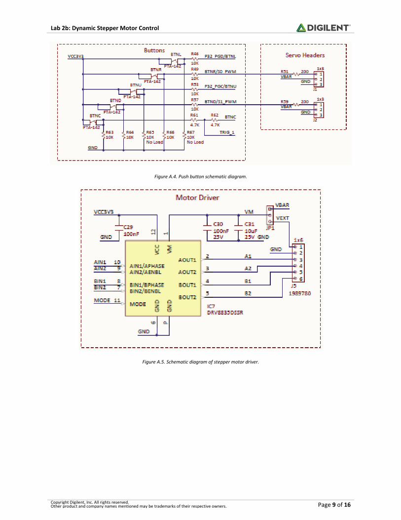
Figure A.4. Push button schematic diagram.
Figure A.5. Schematic diagram of stepper motor driver.
Page 10
Lab 2b: Dynamic Stepper Motor Control
Copyright Digilent, Inc. All rights reserved. Other product and company names mentioned may be trademarks of their respective owners. Page 10 of 16
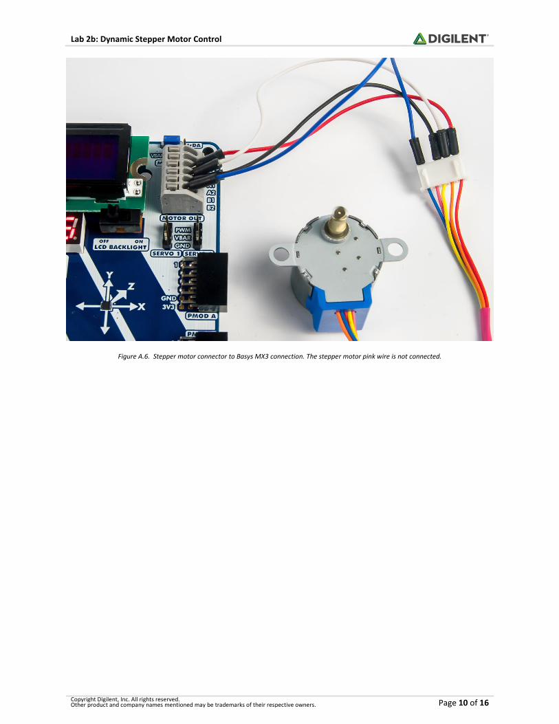
Figure A.6. Stepper motor connector to Basys MX3 connection. The stepper motor pink wire is not connected.
Page 11
Lab 2b: Dynamic Stepper Motor Control
Copyright Digilent, Inc. All rights reserved. Other product and company names mentioned may be trademarks of their respective owners. Page 11 of 16
Appendix B: Introduction to Stepper Motors and Finite State
Machines
Stepper motors are variable reluctance electric motors that are designed to control the angular position of the
rotor shaft in discrete steps. The stepper motor consists of two sets of field windings positioned around a
permanent magnet rotor. The combinations of voltages applied to the four control terminals of the field windings
control the magnitude and direction of the current through the windings. The electrical current through the
windings create an electromagnet. The motor shaft rotates to a position that minimizes the reluctance path
between the field winding electromagnet’s north/south poles and those of the permanent magnet rotor.
Figure B.1. Bipolar (4 wire) Stepper motor diagram.
Figure B.2. Wiring configurations for 5, 6, and 8 wire stepper motor.
Considering the combinations of voltages on the winding terminals as possible control states, there are only eight
states that produce current in the field windings, as shown in Table B.1 below. In order to move the rotator shaft
from one stable position to the physically adjacent stable position, the control voltages must switch to one of four
out of the eight possible combinations of voltages. The action of moving from one stable position to an adjacent
stable position is referred to as either a full-step or a half-step. Half-step increments are half the angular rotation
of full-steps. Repeating a sequence of full-step or half-step movements at a high speed uniform rate will cause the
rotator shaft to appear to rotate at a constant speed albeit in discrete steps.
Table B.1. Stepper motor control codes.
Step Control Winding Voltage
Step Name Hex Code “1a” “1b” “2a” “2b”
S0_5 0x0A H L H L
S1 0x08 H L L L
Page 12
Lab 2b: Dynamic Stepper Motor Control
Copyright Digilent, Inc. All rights reserved. Other product and company names mentioned may be trademarks of their respective owners. Page 12 of 16
S1_5 0x09 H L L H
S2 0x01 L L L H
S2_5 0x05 L H L H
S3 0x04 L H L L
S3_5 0x06 L H H L
S0 0x02 L L H L
The stepper motor used in Lab 2b is configured as a 5 wire motor, as shown in Fig. B.2, and is designed to require
nominally 1600 full steps for the rotor shaft to complete one full revolution, or 0.225 degrees per step. 3200 half-
steps are required to make one revolution, or 0.1125 degrees per half-step. The first column in Table B.1 is a label
assigned to the state. The second column is the hexadecimal code that will set the processor’s I/O pins to control
the voltages on the terminals of the windings. The last four columns in Table B.1 represent the combinations of
voltages on the field windings that produce stable rotator shaft positions. The letter “H” denotes a high voltage
and the letter “L” denotes a low voltage. As shown in Fig. B.1, current flows through a motor coil when there is a
voltage difference across the winding. The voltage combinations for step 3 (S3) in Table B.1 represent the
combination to produce the current flow shown in Fig. B.1.
The four winding terminal designations shown in Table B.1 are assigned to I/O pins, as shown in Appendix C. The
stepper motor will move to the nearest stable position generated by the voltages associated with the hexadecimal
codes shown in the second column. The stepper motor will be held in a fixed position until the voltages on the
windings change.
If the motor is to rotate the motor shaft in a clockwise direction using the full-step mode, the sequence of output
codes that must be sent to the motor are represented by steps S1, S2, S3, S4, S1, etc. A 1600-step per revolution
motor will require the sequence of the four output combinations, S1 through S4, to be repeated 400 times for the
rotator shaft to make exactly one revolution. If operating in half-step mode, then the eight-step sequence of S0,
S0_5, S1, S1_5, S2, S2_5, etc., must also be repeated 400 times for the rotator shaft to make a complete
revolution. Sequencing in one direction (up or down) through the output code found in Table II causes the rotator
shaft to rotate in one direction. Reversing this sequence causes the rotator shaft to rotate in the opposite
direction.
B.1 Connecting the Stepper Motor to the Basys MX3
The Basys MX3 processor platform uses a DRV8835DSSR driver module that interfaces with the PIC32 processor, as
shown in Fig. A.5. Referring to Table C.1 of Appendix C, we can generate Table B.2 below to assist in the
initialization and operation of the stepper motor. All pins must be set as outputs. The RB3 pin used for AIN1 and
the RB5 pin used for BIN2 must also have the analog functionality disabled using the instructions
“ANSELBbits.ANSB5 = 0” and “ANSELBbits.ANSB5 = 0.” Based on the data sheet for the DRV8835DSSR driver, the
“mode” input must be set low using the output from RF1.
Since an external 5.0 V supply will be used to power the stepper motor, connected to J11, the jumper pin must be
set for the VBAR position on the top right corner of the Basys MX3 processor board. The stepper motor is
connected to the Basys MX3 board as shown in Table B.2.
Table B.2. PIC32 to Stepper Motor Driver Connections.
PIC32 PORT PIC32 PIN Driver Input Motor Output Stepper Motor
RB3 PGED3/AN3/C2INA/RPB3/RB3 AIN1 AIN1 Red
RE8 RPE8/RE8 AIN2 AIN2 Orange
Page 13
Lab 2b: Dynamic Stepper Motor Control
Copyright Digilent, Inc. All rights reserved. Other product and company names mentioned may be trademarks of their respective owners. Page 13 of 16
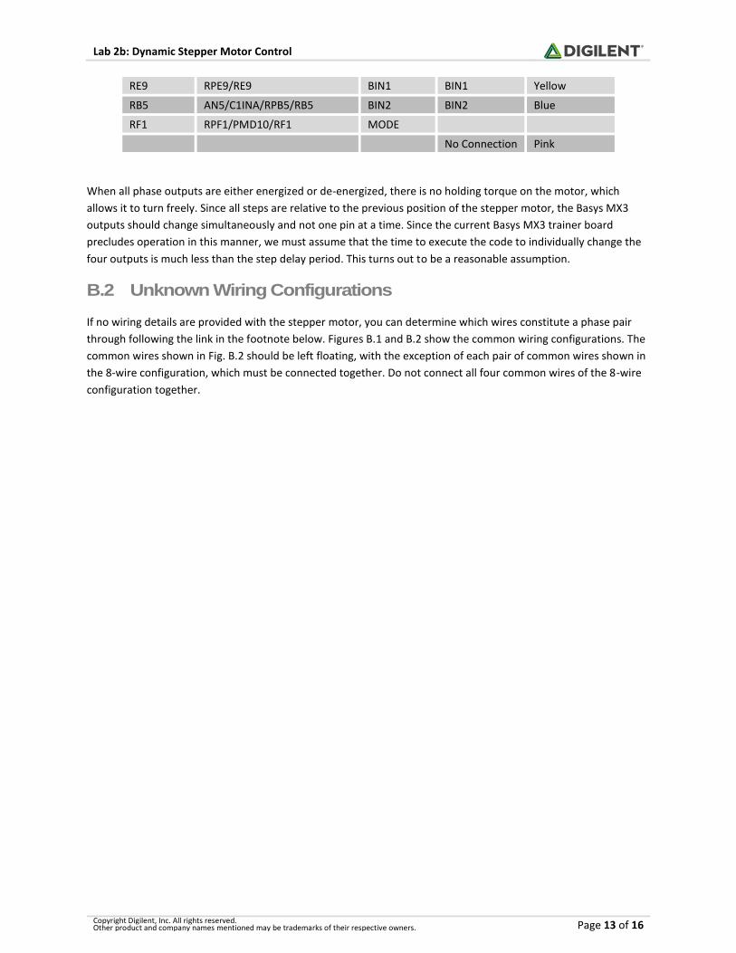
RE9 RPE9/RE9 BIN1 BIN1 Yellow
RB5 AN5/C1INA/RPB5/RB5 BIN2 BIN2 Blue
RF1 RPF1/PMD10/RF1 MODE
No Connection Pink
When all phase outputs are either energized or de-energized, there is no holding torque on the motor, which
allows it to turn freely. Since all steps are relative to the previous position of the stepper motor, the Basys MX3
outputs should change simultaneously and not one pin at a time. Since the current Basys MX3 trainer board
precludes operation in this manner, we must assume that the time to execute the code to individually change the
four outputs is much less than the step delay period. This turns out to be a reasonable assumption.
B.2 Unknown Wiring Configurations
If no wiring details are provided with the stepper motor, you can determine which wires constitute a phase pair
through following the link in the footnote below. Figures B.1 and B.2 show the common wiring configurations. The
common wires shown in Fig. B.2 should be left floating, with the exception of each pair of common wires shown in
the 8-wire configuration, which must be connected together. Do not connect all four common wires of the 8-wire
configuration together.
Page 14
Lab 2b: Dynamic Stepper Motor Control
Copyright Digilent, Inc. All rights reserved. Other product and company names mentioned may be trademarks of their respective owners. Page 14 of 16
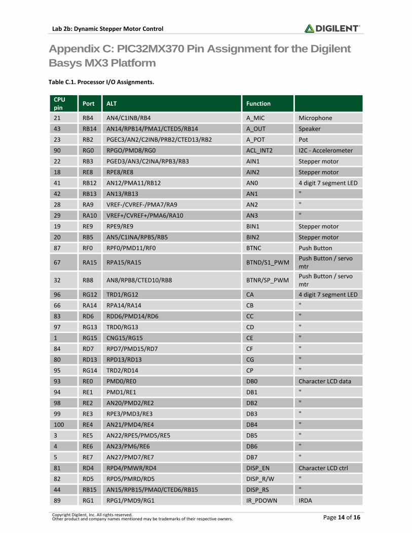
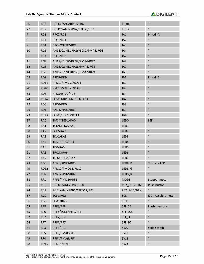
Appendix C: PIC32MX370 Pin Assignment for the Digilent
Basys MX3 Platform
Table C.1. Processor I/O Assignments.
CPU pin
Port ALT Function
21 RB4 AN4/C1INB/RB4 A_MIC Microphone
43 RB14 AN14/RPB14/PMA1/CTED5/RB14 A_OUT Speaker
23 RB2 PGEC3/AN2/C2INB/PRB2/CTED13/RB2 A_POT Pot
90 RG0 RPGO/PMD8/RG0 ACL_INT2 I2C - Accelerometer
22 RB3 PGED3/AN3/C2INA/RPB3/RB3 AIN1 Stepper motor
18 RE8 RPE8/RE8 AIN2 Stepper motor
41 RB12 AN12/PMA11/RB12 AN0 4 digit 7 segment LED
42 RB13 AN13/RB13 AN1 "
28 RA9 VREF-/CVREF-/PMA7/RA9 AN2 "
29 RA10 VREF+/CVREF+/PMA6/RA10 AN3 "
19 RE9 RPE9/RE9 BIN1 Stepper motor
20 RB5 AN5/C1INA/RPB5/RB5 BIN2 Stepper motor
87 RF0 RPF0/PMD11/RF0 BTNC Push Button
67 RA15 RPA15/RA15 BTND/S1_PWM Push Button / servo mtr
32 RB8 AN8/RPB8/CTED10/RB8 BTNR/SP_PWM Push Button / servo mtr
96 RG12 TRD1/RG12 CA 4 digit 7 segment LED
66 RA14 RPA14/RA14 CB "
83 RD6 RDD6/PMD14/RD6 CC "
97 RG13 TRD0/RG13 CD "
1 RG15 CNG15/RG15 CE "
84 RD7 RPD7/PMD15/RD7 CF "
80 RD13 RPD13/RD13 CG "
95 RG14 TRD2/RD14 CP "
93 RE0 PMD0/RE0 DB0 Character LCD data
94 RE1 PMD1/RE1 DB1 "
98 RE2 AN20/PMD2/RE2 DB2 "
99 RE3 RPE3/PMD3/RE3 DB3 "
100 RE4 AN21/PMD4/RE4 DB4 "
3 RE5 AN22/RPE5/PMD5/RE5 DB5 "
4 RE6 AN23/PM6/RE6 DB6 "
5 RE7 AN27/PMD7/RE7 DB7 "
81 RD4 RPD4/PMWR/RD4 DISP_EN Character LCD ctrl
82 RD5 RPD5/PMRD/RD5 DISP_R/W "
44 RB15 AN15/RPB15/PMA0/CTED6/RB15 DISP_RS "
89 RG1 RPG1/PMD9/RG1 IR_PDOWN IRDA
Page 15
Lab 2b: Dynamic Stepper Motor Control
Copyright Digilent, Inc. All rights reserved. Other product and company names mentioned may be trademarks of their respective owners. Page 15 of 16
26 RB6 PGEC2/AN6/RPB6/RB6 IR_RX "
27 RB7 PGED2/AN7/RPB7/CTED3/RB7 IR_TX "
7 RC2 RPC2/RC2 JA1 Pmod JA
6 RC1 RPC1/RC1 JA2 "
9 RC4 RPC4/CTED7/RC4 JA3 "
10 RG6 AN16/C1IND/RPG6/SCK2/PMA5/RG6 JA4 "
8 RC3 RPC3/RC3 JA7 "
11 RG7 AN17/C1INC/RPG7/PMA4/RG7 JA8 "
12 RG8 AN18/C2IND/RPG8/PMA3/RG8 JA9 "
14 RG9 AN19/C2INC/RPG9/PMA2/RG9 JA10 "
69 RD9 RPD9/RD9 JB1 Pmod JB
71 RD11 RPD11/PMCS1/RD11 JB2 "
70 RD10 RPD10/PMCS2/RD10 JB3 "
68 RD8 RPD8/RTCC/RD8 JB4 "
74 RC14 SOSCO/RPC14/T1CK/RC14 JB7 "
72 RD0 RPD0/RD0 JB8 "
76 RD1 AN24/RPD1/RD1 JB9 "
73 RC13 SOSCI/RPC13/RC13 JB10 "
17 RA0 TMS/CTED1/RA0 LED0 LED
38 RA1 TCK/CTED2/RA1 LED1 "
58 RA2 SCL2/RA2 LED2 "
59 RA3 SDA2/RA3 LED3 "
60 RA4 TDI/CTED9/RA4 LED4 "
61 RA5 TD0/RA5 LED5 "
91 RA6 TRCLK/RA6 LED6 "
92 RA7 TD3/CTED8/RA7 LED7 "
78 RD3 AN26/RPD3/RD3 LED8_B Tri-color LED
79 RD12 RPD12/PMD12/RD12 LED8_G "
77 RD2 AN25/RPD2/RD2 LED8_R "
88 RF1 RPF1/PMD10/RF1 MODE Stepper motor
25 RB0 PGED1/AN0/RPB0/RB0 P32_PGC/BTNU Push Button
24 RB1 PGC1/AN1/RPB1/CTED12/RB1 P32_PGD/BTNL "
57 RG2 SCL1/RG2 SCL I2C - Accelerometer
56 RG3 SDA1/RG3 SDA "
53 RF8 RPF8/RF8 SPI_CE Flash memory
55 RF6 RPF6/SCK1/INT0/RF6 SPI_SCK "
52 RF2 RPF2/RF2 SPI_SI "
54 RF7 RPF7/RF7 SPI_SO "
51 RF3 RPF3/RF3 SW0 Slide switch
50 RF5 RPF5/PMA8/RF5 SW1 "
49 RF4 RPF4/PMA9/RF4 SW2 "
48 RD15 RPD15/RD15 SW3 "
Page 16
Lab 2b: Dynamic Stepper Motor Control
Copyright Digilent, Inc. All rights reserved. Other product and company names mentioned may be trademarks of their respective owners. Page 16 of 16
47 RD14 RPD14/RD14 SW4 "
35 RB11 AN11/PMA12/RB11 SW5 "
34 RB10 CVREFOUT/AN10/RPB10/PMA13/CTED11/RB10 SW6 "
33 RB9 AN9/RPB9/CTED4/RB9 SW7 "
39 RF13 RPF13/RF13 UART_RX FTDI receive
40 RF12 RPF12/RF12 UART_TX FTDI transmit
63 RC12 CLKI/RC12/OSC1
64 RC15 CLKO/RC15/OSC2