37
LAB MANUAL TRANSPORTATION ENGINEERING LAB DEPARTMENT OF CIVIL ENGINEERING JTANI,RAMACHANDRAPUR,BHUBANESWAR,752050

LAB MANUAL
TRANSPORTATION ENGINEERING LAB
DEPARTMENT OF CIVIL ENGINEERING
JTANI,RAMACHANDRAPUR,BHUBANESWAR,752050

TRANSPORTATION ENGINEERING LAB
LAB MANUAL
(FOR B.TECH PROGRAMME)
Name :
Branch :
Roll No. :
Registration No. :
Group :
DEPARTMENT OF CIVIL ENGINEERING
CENTURION INSTITUTE OF TECHNOLOGY
JATNI, BHUBANESWAR

Laboratory Manual for
TRANSPORTATION ENGG. LAB
First Release, DEC 2013
Compiled by:
Dr. Ramakanta Panigrahi [Professor]
&
Mrs. Sipalin Nayak Routray [Lecturer]
Department of Civil Engineering
Centurion Institute of Technology,
Jatni, Bhubaneswar.
All rights reserved. No part of this manual may be
reproduced, stored in a retrieval system, or
transmitted in any form or by any means, electronic,
mechanical, photocopying, recording or otherwise
(except for the internal use of CUTM students
during the laboratory work as directed by the
faculty in-charge), without prior written permission
of the HOD, Department of Civil Engineering,
Centurion Institute of Technology, Bhubaneswar.
ABSTRACT
Transportation engineering is the application of technology and scientific principles to the
planning, functional design, operation and management of facilities for any mode of
transportation in order to provide safe, efficient, rapid, comfortable, convenient,
economical, and environmentally compatible movement of people and goods• It is a sub-
discipline of civil engineering and of industrial engineering. Transportation engineering is
a major component of the civil engineering and mechanical engineering disciplines,
according to specialization of academic courses and main competences of the involved
territory.
• The study of transportation engineering lab enables the students in integrating laboratory
work into the course learning versus allowing students to direct the learning
independently.
This invited paper for the session on Transportation Engineering Education wrestles with
these issues and others, providing suggestions for how faculty may choose to set
priorities in making choices about the design and implementation of learning in the area
of transportation related construction work.
Dr. Ramakanta Panigrahi
HOD, Department of Civil Engineering,
Centurion Institute of Technology, Bhubaneswar

Exp.No. Name of the
Experiments
Date of
submission
Page
No.
Check-
ed by
Evaluation
Result
(10 point
scale)

LIST OF EXPERIMENTS
1. Determination of aggregate crushing value.
2. Determination of Los Angeles abrasion value of aggregates.
3. Determination of aggregate impact value.
4. Determination of penetration value of bitumen.
5. Determination of softening point value of bitumen.
6. Determination of ductility value of bitumen.
7. Determination of flash and fire point of bitumen.
8. Determination of specific gravity of bitumen.
9. Determination of stripping value of aggregate
10. Determination of flakiness index and elongation index of coarse aggregate
11. Determination of specific gravity and water absorption of coarse aggregate.
12. CBR test for soil.

EXPERIMENT 01
EXPERIMENT 02
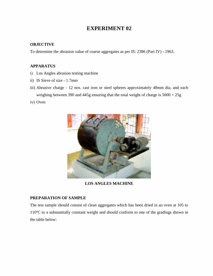
OBJECTIVE
To determine the abrasion value of coarse aggregates as per IS: 2386 (Part IV) - 1963.
APPARATUS
i) Los Angles abrasion testing machine
ii) IS Sieve of size - 1.7mm
iii) Abrasive charge - 12 nos. cast iron or steel spheres approximately 48mm dia. and each
weighing between 390 and 445g ensuring that the total weight of charge is 5000 + 25g
iv) Oven
LOS ANGLES MACHINE
PREPARATION OF SAMPLE
The test sample should consist of clean aggregates which has been dried in an oven at 105 to
110oC to a substantially constant weight and should conform to one of the gradings shown in
the table below:

Grading of test samples
Sieve size
(square hole)
Weight of g of test sample for grade
A B C D E F G
Passing
Through
(mm)
Retained
on
(mm)
80 63 - - - - 2500* - -
63 50 - - - - 2500* 5000*
50 40 - - - - - 5000* 5000*
40 25 1250 - - - - - 5000*
25 20 1250 - - - - - -
20 12.5 1250 2500 - - - - -
12.5 10 1250 2500 - - - - -
10 6.3 - - 2500 - - - -
6.3 4.75 - - 2500 - - - -
4.75 2.36 - - - 5000 - - -
PROCEDURE
i) The test sample and the abrasive charge is placed in the Los Angles abrasion testing
machine and the machine is rotated at a speed of 20 to 33 revolutions/minute for 1000
revolutions.
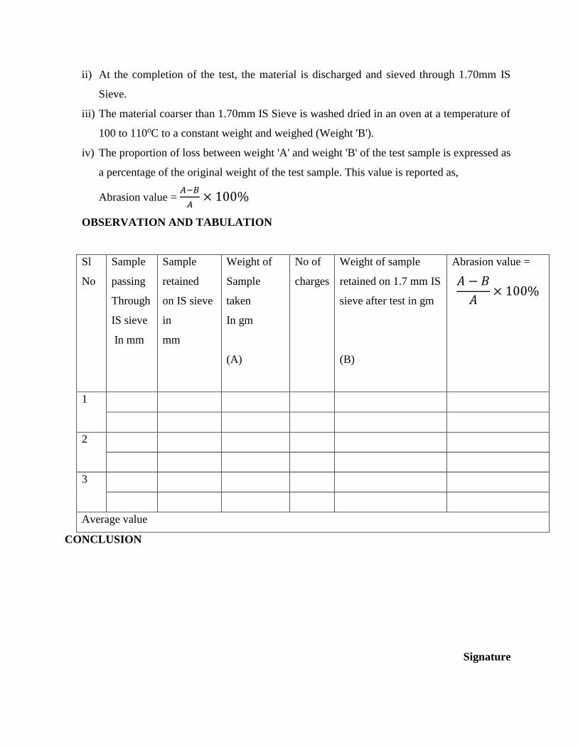
ii) At the completion of the test, the material is discharged and sieved through 1.70mm IS
Sieve.
iii) The material coarser than 1.70mm IS Sieve is washed dried in an oven at a temperature of
100 to 110oC to a constant weight and weighed (Weight 'B').
iv) The proportion of loss between weight 'A' and weight 'B' of the test sample is expressed as
a percentage of the original weight of the test sample. This value is reported as,
Abrasion value = 𝐴−𝐵
𝐴× 100%
OBSERVATION AND TABULATION
Sl
No
Sample
passing
Through
IS sieve
In mm
Sample
retained
on IS sieve
in
mm
Weight of
Sample
taken
In gm
(A)
No of
charges
Weight of sample
retained on 1.7 mm IS
sieve after test in gm
(B)
Abrasion value =
𝐴 − 𝐵
𝐴× 100%
1
2
3
Average value
CONCLUSION
Signature
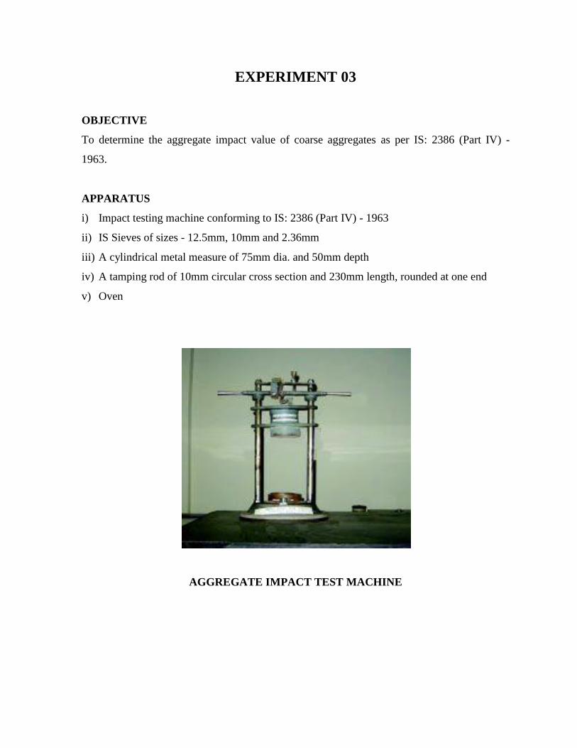
EXPERIMENT 03
OBJECTIVE
To determine the aggregate impact value of coarse aggregates as per IS: 2386 (Part IV) -
1963.
APPARATUS
i) Impact testing machine conforming to IS: 2386 (Part IV) - 1963
ii) IS Sieves of sizes - 12.5mm, 10mm and 2.36mm
iii) A cylindrical metal measure of 75mm dia. and 50mm depth
iv) A tamping rod of 10mm circular cross section and 230mm length, rounded at one end
v) Oven
AGGREGATE IMPACT TEST MACHINE

PREPARATION OF SAMPLE
i) The test sample is conformed to the following grading: - Passing through 12.5mm IS
Sieve 100% - Retention on 10mm IS Sieve 100%
ii) The sample is oven-dried for 4hrs. at a temperature of 100 to 110oC and cooled.
iii) The measure is about one-third full with the prepared aggregates and tamped with 25
strokes of the tamping rod.
i) A further similar quantity of aggregates is added and a further tamping of 25 strokes
given. The measure is finally to be filled to overflow, tamped 25 times and the surplus
aggregates struck off, using a tamping rod as a straight edge.
ii) The net weight of the aggregates in the measure is determined to the nearest gram (Weight
'A').
PROCEDURE
i) The cup of the impact testing machine is fixed firmly in position on the base of the
machine and the whole of the test sample is placed in it and compacted by 25 strokes of
the tamping rod.
ii) The hammer is raised to 380mm above the upper surface of the aggregates in the cup and
allowed to fall freely onto the aggregates.
iii) The test sample is subjected to a total of 15 such blows, each being delivered at an interval
of not less than one second.
iv) The sample is removed and sieved through a 2.36mm IS Sieve. The fraction passing
through is weighed (Weight 'B').
v) The fraction is retained on the sieve should also be weighed (Weight 'C') and if the total
weight (B+C) is less than the initial weight (A) by more than one gram, the result is
discarded and a fresh test done.
vi) The ratio of the weight of the fines formed to the total sample weight is expressed as a
percentage.
vii) Aggregate impact value is obtained by the relation (B/A) x 100%
viii) Two such tests is carried out and the mean of the results is reported. A sample proforma
for the record of the test results is given in
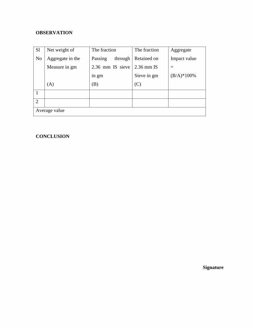
OBSERVATION
Sl
No
Net weight of
Aggregate in the
Measure in gm
(A)
The fraction
Passing through
2.36 mm IS sieve
in gm
(B)
The fraction
Retained on
2.36 mm IS
Sieve in gm
(C)
Aggregate
Impact value
=
(B/A)*100%
1
2
Average value
CONCLUSION
Signature

EXPERIMENT 04
OBJECTIVE
To determine the penetration of bitumen as per IS: 1203 - 1978.
THEORY
The penetration of a bituminous material is the distance in tenths of a mm, that a standard
needle would penetrate vertically, into a sample of the material under standard conditions of
temperature load and time.
APPARATUS REQUIRED
i) Penetrometer
ii) Water bath
iii) Bath thermometer - Range 0 to 44oC, Graduation 0.2oC
PENETROMETER
SAMPLE
Bitumen should be just sufficient to fill the container to a depth of at least 15mm in excess of
the expected penetration.
PROCEDURE
i) The bitumen above the softening point (between 75 and 100oC) is softened. It is stirred
thoroughly to remove air bubbles and water.
ii) It is poured into a container to a depth of at least 15mm in excess of the expected
penetration.
iii) It is cooled at an atmospheric temperature of 15 to 30oC for 2 1 hrs. Then it is placed in a
transfer dish in the water bath at 25.0 + 0.1oC for 2 1
iv) The container is kept on the stand of the penetration apparatus.
v) The needle is adjusted to make contact with the surface of the sample.
vi) The dial reading is adjusted to zero. Is adjusted.
vii) With the help of the timer, the needle is released for exactly 5 seconds.
viii) The dial reading is recorded.
ix) The above procedure is repeated for thrice.
OBSERVATION
CONCLUSION
Signature
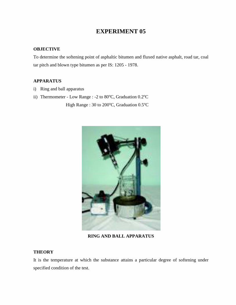
EXPERIMENT 05
OBJECTIVE
To determine the softening point of asphaltic bitumen and fluxed native asphalt, road tar, coal
tar pitch and blown type bitumen as per IS: 1205 - 1978.
APPARATUS
i) Ring and ball apparatus
ii) Thermometer - Low Range : -2 to 80oC, Graduation 0.2oC
High Range : 30 to 200oC, Graduation 0.5oC
RING AND BALL APPARATUS
THEORY
It is the temperature at which the substance attains a particular degree of softening under
specified condition of the test.
PREPARATION OF SAMPLE
i) The sample is just sufficient to fill the ring. The excess sample is cut off by a knife.
ii) The material is heated between 75 and 100oC. Stir it to remove air bubbles and water, and
filter it through IS Sieve 30, if necessary.
iii) The rings are heated and glycerin is applied. The material is filled in it and is cooled it for
30 minutes.
iv) The excess material is removed with the help of a warmed, sharp knife.
PROCEDURE
A) Materials of softening point below 80oC:
i) The apparatus is assembled with the rings, thermometer and ball guides in position.
ii) The beaker is filled with boiled distilled water at a temperature 5.0 ± 0.5oC per minute.
iii) With the help of a stirrer, stir the liquid and heat is applied to the beaker at a temperature
of 5.0 ± 0.5oC per minute.
iv) The heat is applied until the material softens and the ball is allowed to pass through the
ring.
v) The temperature is recorded at which the ball touches the bottom, which is nothing but the
softening point of that material.
B) Materials of softening point above 80oC:
i) The procedure is the same as described above. The only difference is that instead of water,
glycerine is used and the starting temperature of the test is 35oC.
OBSERVATION
CONCLUSION
Signature
EXPERIMENT 06
OBJECTIVE
To determine the ductility of distillation residue of cutback bitumen, blown type bitumen and
other bituminous products as per IS: 1208 - 1978.
THEORY
The ductility of a bituminous material is measured by the distance in cm to which it will
elongate before breaking when a standard briquette specimen of the material is pulled apart at
a specified speed and a specified temperature.
APPARATUS
i) Standard mould
ii) Water bath
iii) Testing machine
iv) Thermometer - Range 0 to 44oC, Graduation 0.2oC
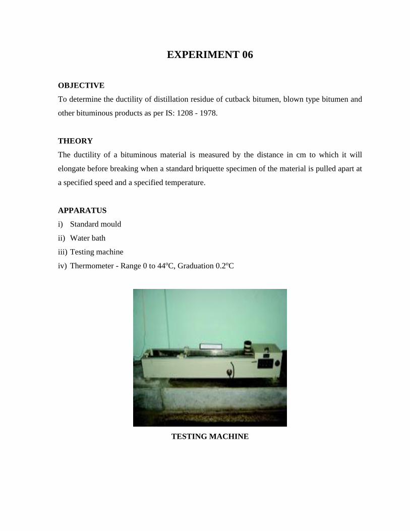
TESTING MACHINE

PROCEDURE
i) The bituminous material is tested is completely melt by heating it to a temperature of 75
to 100oC above the approximate softening point until it becomes thoroughly fluid.
ii) The mould is assembled on a brass plate and in order the material is prevented under test
from sticking, thoroughly coat the surface of the plate and the interior surfaces of the sides
of the mould with a mixture of equal parts of glycerine and dextrin.
iii) While filling, the material is poured in a thin stream back and forth from end to end of the
mould until it is more than level full. It is leaved to cool at room temperature for 30 to 40
minutes and then it is placed in a water bath maintained at the specified temperature for 30
minutes, after which cut off the excess bitumen by means of a hot, straight-edged putty
knife or spatula, so that the mould is just level full.
iv) The brass plate and mould is placed with briquette specimen in the water bath and it is
kept at the specified temperature for about 85 to 95 minutes. The briquette is removed
from the plate; detach the side pieces and the briquette immediately.
v) The rings are attached at each end of the two clips to the pins or hooks in the testing
machine and the two clips are pulled apart horizontally at a uniform speed, as specified,
until the briquette ruptures.
vi) The distance is measured in cm through which the clips have been pulled to produce
rupture.
vii) While the test is being done, the specimen both above and below by at least 25mm is
covered with water in the tank of the testing machine and the temperature is maintained
continuously within ± 0.5oC of the specified temperature.
OBSERVATION
CONCLUSION
Signature

EXPERIMENT 07
OBJECTIVE
To determine the flash point and the fire point of asphaltic bitumen and fluxed native asphalt,
cutback bitumen and blown type bitumen as per IS: 1209 - 1978.
APPARATUS REQUIRED
A) Pensky-Martens apparatus
B) Thermometer- Low Range : -7 to 110oC, Graduation 0.5oC
High Range : 90 to 370oC, Graduation 2oC
THEORY
Flash Point - The flash point of a material is the lowest temperature at which the application
of test flame causes the vapors from the material to momentarily catch fire in the form of a
flash under specified conditions of the test.
Fire Point - The fire point is the lowest temperature at which the application of test flame
causes the material to ignite and burn at least for 5 seconds under specified conditions of the
test.
PENSKY - MARTENS APPARATUS
PROCEDURE
A) FLASH POINT
i) The bitumen is softened between 75 and 100oC. It is stirred thoroughly to removed air
bubbles and water.
ii) The cup is filled with the material to be tested up to the filling mark. It is placed on the
bath. The open clip is fixed thermometer is inserted of high or low range as per
requirement and also the stirrer, to stir it.
iii) The test flame is lighted, and it is adjusted.
i) The heat is supplied at such a rate that the temperature is increased; the thermometer is
recorded neither less than 5oC nor more than 6oC per minute.
ii) Open flash point is taken as that temperature when a flash first appears at any point on the
surface of the material in the cup.
iii) Care is taken so that the bluish halo that sometimes surrounds the test flame is not
confused with the true flash. Discontinue the stirring during the application of the test
flame.
iv) Flash point is taken as the temperature read on the thermometer at the time the flash
occurs.
B) FIRE POINT
i) After flash point, heating is continued at such a rate that the increase in temperature is
recorded by the thermometer is neither less than 5oC nor more than 6oC per minute.
ii) The test flame is lighted and adjusted so that it is of the size of a bead 4mm in dia.
OBSERVATION
CONCLUSION
Signature
EXPERIMENT 08
OBJECTIVE
To determine the specific gravity of semi-solid bitumen road tars, creosote and anthracite oil
as per IS: 1202 - 1978.
THEORY
It is the ratio of mass of a given volume of bitumen to the mass of an equal volume of water,
both taken at a recorded/specified temperature.
APPARATUS
i) Specific gravity bottles of 50ml capacity
ii) Water bath
iii) Bath thermometer - Range 0 to 44oC, Graduation 0.2oC
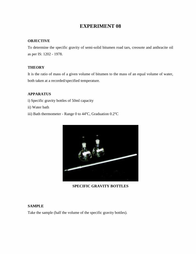
SPECIFIC GRAVITY BOTTLES
SAMPLE
Take the sample (half the volume of the specific gravity bottles).
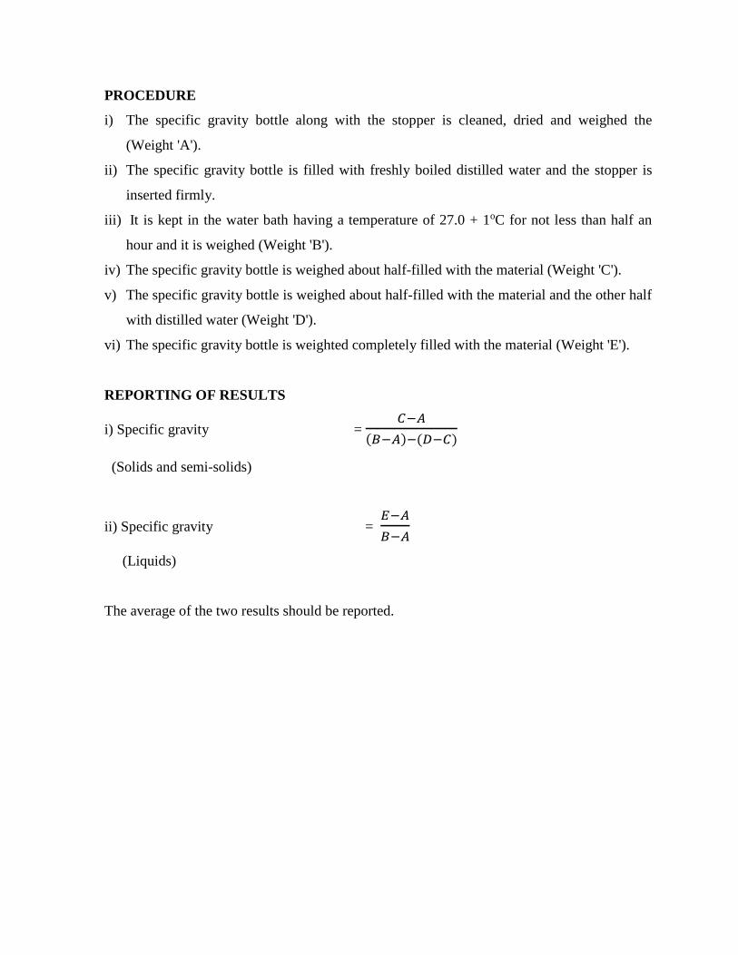
PROCEDURE
i) The specific gravity bottle along with the stopper is cleaned, dried and weighed the
(Weight 'A').
ii) The specific gravity bottle is filled with freshly boiled distilled water and the stopper is
inserted firmly.
iii) It is kept in the water bath having a temperature of 27.0 + 1oC for not less than half an
hour and it is weighed (Weight 'B').
iv) The specific gravity bottle is weighed about half-filled with the material (Weight 'C').
v) The specific gravity bottle is weighed about half-filled with the material and the other half
with distilled water (Weight 'D').
vi) The specific gravity bottle is weighted completely filled with the material (Weight 'E').
REPORTING OF RESULTS
i) Specific gravity = 𝐶−𝐴
(𝐵−𝐴)−(𝐷−𝐶)
(Solids and semi-solids)
ii) Specific gravity = 𝐸−𝐴
𝐵−𝐴
(Liquids)
The average of the two results should be reported.
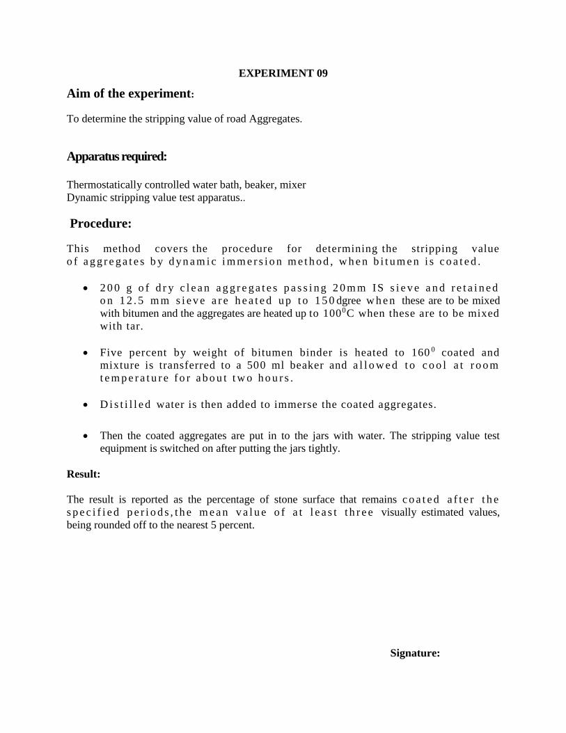
EXPERIMENT 09
Aim of the experiment:
To determine the stripping value of road Aggregates.
Apparatus required:
Thermostatically controlled water bath, beaker, mixer
Dynamic stripping value test apparatus..
Procedure:
This method covers the procedure for determining the stripping value
o f a g g r e g a t e s b y d yn a m i c i m m e r s i o n m e t h o d , w h e n b i t u m e n i s c o a t e d .
2 0 0 g o f d r y c l e a n a g g r e g a t e s p a s s i n g 2 0 m m IS s i e v e a n d r e t a i n e d
o n 1 2 . 5 m m s i ev e a r e h e a t e d u p t o 1 5 0 dgree w h e n these are to be mixed
with bitumen and the aggregates are heated up to 1000C when these are to be mixed
with tar.
Five percent by weight of bitumen binder is heated to 160 0 coated and
mixture is transferred to a 500 ml beaker and a l l o w e d t o c o o l a t r o o m
t e m p e r a t u r e f o r a b o u t t w o h o u r s .
D i s t i l l e d water is then added to immerse the coated aggregates.
Then the coated aggregates are put in to the jars with water. The stripping value test
equipment is switched on after putting the jars tightly.
Result:
The result is reported as the percentage of stone surface that remains c o a t e d a f t e r t h e
s p e c i f i e d p e r i o d s , t h e m e a n v a l u e o f a t l e a s t t h r e e visually estimated values,
being rounded off to the nearest 5 percent.
Signature:
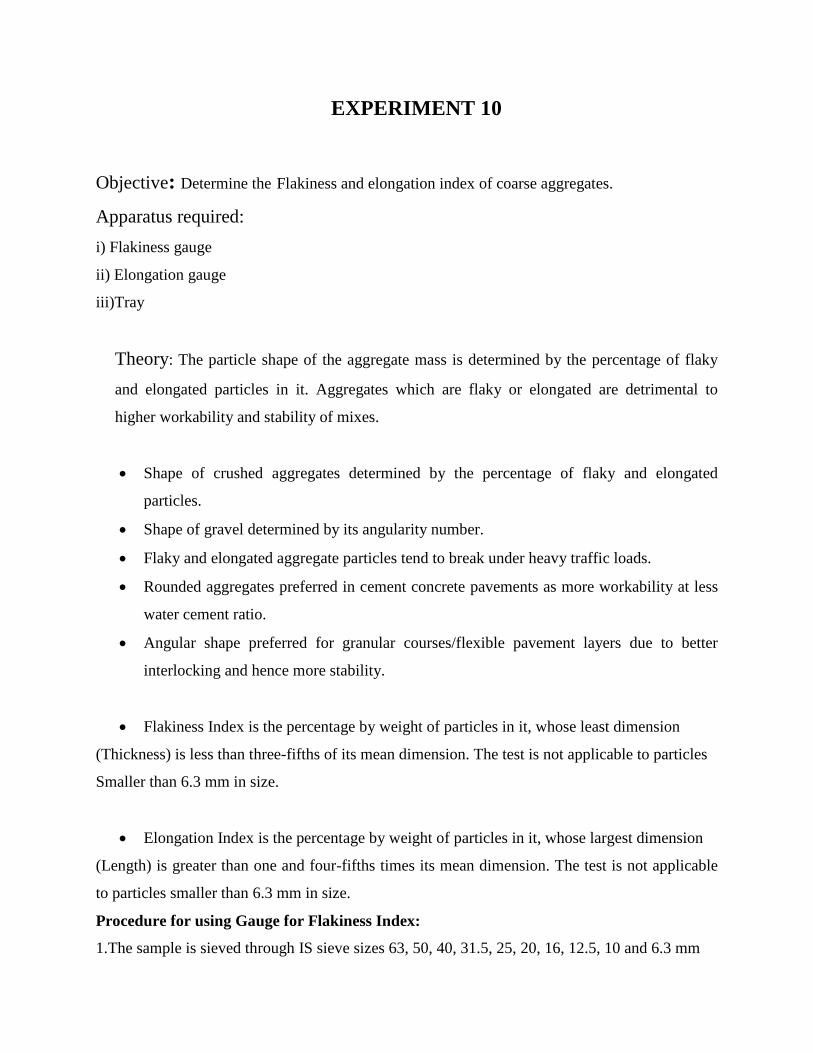
EXPERIMENT 10
Objective: Determine the Flakiness and elongation index of coarse aggregates.
Apparatus required:
i) Flakiness gauge
ii) Elongation gauge
iii)Tray
Theory: The particle shape of the aggregate mass is determined by the percentage of flaky
and elongated particles in it. Aggregates which are flaky or elongated are detrimental to
higher workability and stability of mixes.
Shape of crushed aggregates determined by the percentage of flaky and elongated
particles.
Shape of gravel determined by its angularity number.
Flaky and elongated aggregate particles tend to break under heavy traffic loads.
Rounded aggregates preferred in cement concrete pavements as more workability at less
water cement ratio.
Angular shape preferred for granular courses/flexible pavement layers due to better
interlocking and hence more stability.
Flakiness Index is the percentage by weight of particles in it, whose least dimension
(Thickness) is less than three-fifths of its mean dimension. The test is not applicable to particles
Smaller than 6.3 mm in size.
Elongation Index is the percentage by weight of particles in it, whose largest dimension
(Length) is greater than one and four-fifths times its mean dimension. The test is not applicable
to particles smaller than 6.3 mm in size.
Procedure for using Gauge for Flakiness Index:
1.The sample is sieved through IS sieve sizes 63, 50, 40, 31.5, 25, 20, 16, 12.5, 10 and 6.3 mm
2. Minimum 200 pieces of each fraction to be tested are taken and weighed (W1 gm).
3. Separate the flaky material by using the standard thickness gauge
Flakiness
The amount of flaky material is weighed to an accuracy of 0.1 percent of the test sample
If W1, W2… Wi are the total weights of each size of aggregates taken
If x1 x2….Xiare the weights of material passing the different thickness gauges then:
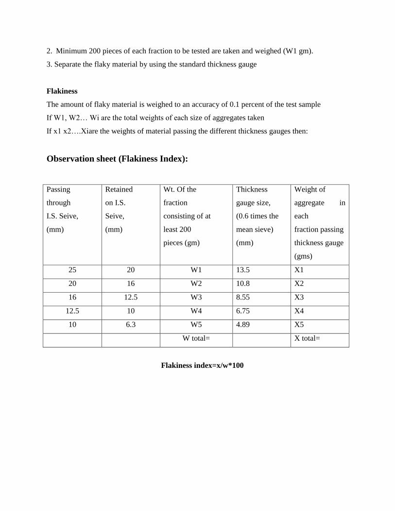
Observation sheet (Flakiness Index):
Passing
through
I.S. Seive,
(mm)
Retained
on I.S.
Seive,
(mm)
Wt. Of the
fraction
consisting of at
least 200
pieces (gm)
Thickness
gauge size,
(0.6 times the
mean sieve)
(mm)
Weight of
aggregate in
each
fraction passing
thickness gauge
(gms)
25 20 W1 13.5 X1
20 16 W2 10.8 X2
16 12.5 W3 8.55 X3
12.5 10 W4 6.75 X4
10 6.3 W5 4.89 X5
W total= X total=
Flakiness index=x/w*100
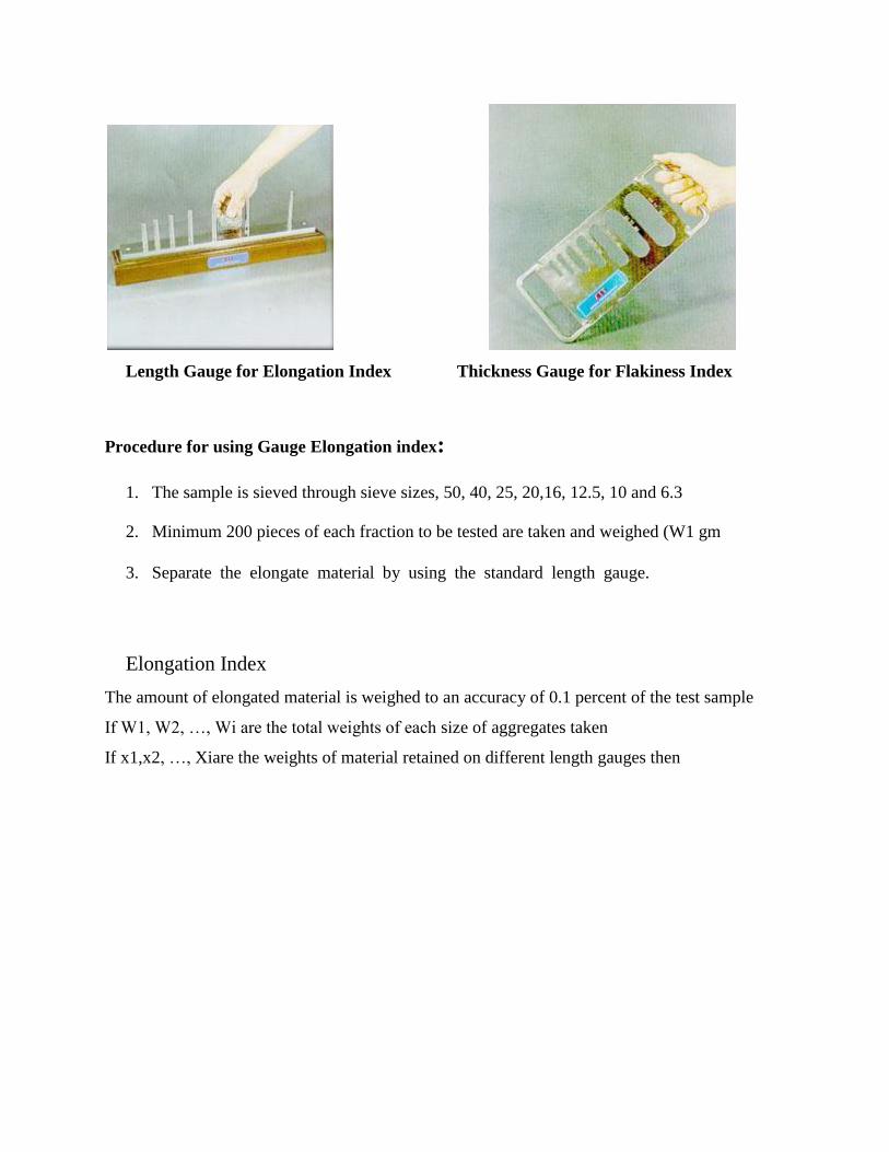
Length Gauge for Elongation Index Thickness Gauge for Flakiness Index
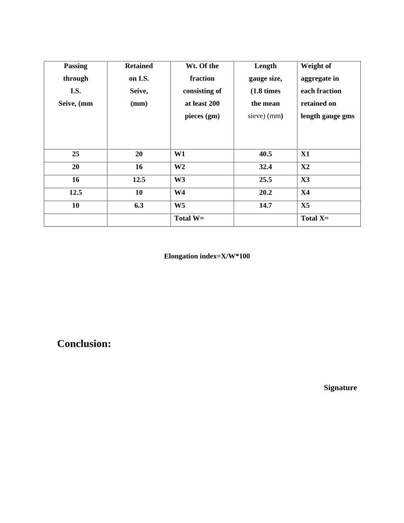
Procedure for using Gauge Elongation index:
1. The sample is sieved through sieve sizes, 50, 40, 25, 20,16, 12.5, 10 and 6.3the
2. Minimum 200 pieces of each fraction to be tested are taken and weighed (W1 gm
3. Separate the elongate material by using the standard length gauge..elongated
material by using gauge e test
Elongation Index
The amount of elongated material is weighed to an accuracy of 0.1 percent of the test sample
If W1, W2, …, Wi are the total weights of each size of aggregates taken
If x1,x2, …, Xiare the weights of material retained on different length gauges then
Passing
through
I.S.
Seive, (mm
Retained
on I.S.
Seive,
(mm)
Wt. Of the
fraction
consisting of
at least 200
pieces (gm)
Length
gauge size,
(1.8 times
the mean
sieve) (mm)
Weight of
aggregate in
each fraction
retained on
length gauge gms
25 20 W1 40.5 X1
20 16 W2 32.4 X2
16 12.5 W3 25.5 X3
12.5 10 W4 20.2 X4
10 6.3 W5 14.7 X5
Total W= Total X=
Elongation index=X/W*100
Conclusion:
Signature
EXPERIMENT 11
OBJECTIVE
To determine the water absorption of coarse aggregates as per IS: 2386 (Part III) - 1963.
APPARATUS
i) Wire basket - perforated, electroplated or plastic coated with wire hangers for suspending
it from the balance
ii) Water-tight container for suspending the basket
iii) Dry soft absorbent cloth - 75cm x 45cm (2 nos.)
iv) Shallow tray of minimum 650 sq.cm area
v) Air-tight container of a capacity similar to the basket
vi) Oven
SAMPLE
A sample not less than 2000g should be used.
PROCEDURE
i) The sample is thoroughly washed to remove finer particles and dust, drained and then it
placed in the wire basket and it is immersed in distilled water at a temperature between 22
and 32oC.
ii) After immersion, the entrapped air is removed by lifting the basket and allowing it to drop
25 times in 25 seconds.
iii) The basket and sample is remained immersed for a period of 24 + ½ hrs after wards.
iv) The basket and aggregates should then be removed from the water, allowed to drain for a
few minutes, after which the aggregates is gently emptied from the basket on to one of the
dry clothes and gently surface-dried with the cloth, transferring it to a second dry cloth
when the first would remove no further moisture.
v) The aggregates is spread on the second cloth and exposed to the atmosphere away from
direct sunlight till it appears to be completely surface-dry.
vi) The aggregates are weighed (Weight 'A').
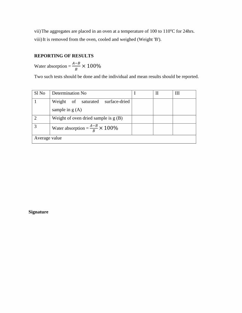
vii) The aggregates are placed in an oven at a temperature of 100 to 110oC for 24hrs.
viii) It is removed from the oven, cooled and weighed (Weight 'B').
REPORTING OF RESULTS
Water absorption = 𝐴−𝐵
𝐵× 100%
Two such tests should be done and the individual and mean results should be reported.
Sl No Determination No I II III
1 Weight of saturated surface-dried
sample in g (A)
2 Weight of oven dried sample is g (B)
3 Water absorption = 𝐴−𝐵
𝐵× 100%
Average value
Signature
EXPERIMENT 12
OBJECTIVE
To determine the California bearing ratio by conducting a load penetration test in the laboratory.
EQUIPMENTS
a) Cylindrical mould with inside dia 150 mm and height 175 mm, provided with a detachable
extension collar 50 mm height and a detachable perforated base plate 10 mm thick.
b) Spacer disc 148 mm in dia and 47.7 mm in height along with handle.
c) Metal rammers. Weight 2.6 kg with a drop of 310 mm (or) weight 4.89 kg a drop 450
mm.
d) Weights. One annular metal weight and several slotted weights weighing 2.5 kg each, 147
mm in dia, with a central hole 53 mm in diameter.
e) Loading machine. With a capacity of atleast 5000 kg and equipped with a movable head
or base that travels at an uniform rate of 1.25 mm/min. Complete with load indicating
device.
f) Metal penetration piston 50 mm dia and minimum of 100 mm in length.
g) Two dial gauges reading to 0.01 mm.
h) Sieves. 4.75 mm and 20 mm I.S. Sieves.
i) Miscellaneous apparatus, such as a mixing bowl, straight edge, scales soaking tank or pan,
drying
THEORY
The California bearing ratio test is penetration test meant for the evaluation of subgrade strength
of roads and pavements. The results obtained by these tests are used with the empirical curves
to determine the thickness of pavement and its component layers. This is the most widely
used method for the design of flexible pavement.
This instruction sheet covers the laboratory method for the determination of C.B.R. of
undisturbed and remoulded /compacted soil specimens, both in soaked as well as unsoaked
state.oven, filter paper and containers.

DEFINITION OF C.B.R.
It is the ratio of force per unit area required to penetrate a soil mass with standard circular piston
at the rate of 1.25 mm/min. to that required for the corresponding penetration of a standard
material.
C.B.R. = Test load/Standard load 100
The following table gives the standard loads adopted for different penetrations for the standard
material with a C.B.R. value of 100%
Penetration of plunger (mm) Standard load (kg)
2.5 1370
5.0 2055
7.5 2630
10.0 3180
12.5 3600
The test may be performed on undisturbed specimens and on remoulded specimens
which may be compacted either statically or dynamically.
PREPARATION OF TEST SPECIMEN
Undisturbed specimen
a) The cutting edge to the mould and push is attached into the ground.
b) The soil is removed from the outside of the mould which is pushed in.
c) When the mould is full of soil, it is removed from weighing the soil with the mould or by
any field method near the spot.
Determine the density
Remolded specimen
a) The remoulded specimen is prepared at Proctor’s maximum dry density or any other
density at which C.B.R is required.
b) The specimen is maintained at optimum moisture content or the field moisture as required.
c) The material used should pass 20 mm I.S. sieve but it should be retained on 4.75 mm I.S.
sieve. The specimen is prepared either by dynamic compaction or by static compaction.
Dynamic Compaction
a) 4.5 to 5.5 kg of soil is taken and is thoroughly mixed with the required water.
b) The extension collar and the base plate are fixed to the mould.
c) The spacer disc is inserted over the base (See Fig.38).
d) The filter paper is placed on the top of the spacer disc.
e) The mix soil is compacted in the mould using either light compaction or heavy
compaction.
f) For light compaction, the soil is compacted in 3 equal layers, each layer being given 55
blows by the 2.6 kg rammer.
g) For heavy compaction the soil is compacted in 5 layers, 56 blows to each layer by the 4.89
kg rammer.
h) The collar is removed and soil is trimmed.
i) The mould is turned upside down and the base plate and the displacer disc are removed.
j) The mould with compacted soil is weighed and the bulk density and dry density is
determined.
k) Filter paper is put on the top of the compacted soil (collar side) and the perforated base
plate is clamped on to it.
Static compaction
a) The weight of the wet soil is calculated at the required water content to give the desired
density when occupying the standard specimen volume in the mould from the expression.
W =desired dry density * (1+w) V
Where W = Weight of the wet soil
w = desired water content
V = volume of the specimen in the mould = 2250 cm3 (as per the mould available in
laboratory)
b) The weight W (calculated as above) of the mix soil is taken and it is placed in the mould.
c) A filter paper and the displacer disc are placed on the top of soil.
d) The mould assembly is kept in static loading frame and the displacer disc is compacted by
pressing till the level of disc is reached the top of the mould.
e) The load is kept for some time and then the load is released. The displacer disc is
removed.
f) The test may be conducted for both soaked as well as unsoaked conditions.
g) If the sample is to be soaked, in both cases of compaction, a filter paper is put on the top
of the soil and the adjustable stem and perforated plate is placed on the top of filter paper.
h) Annular weights are put to produce a surcharge equal to weight of base material and
pavement expected in actual construction. Each 2.5 kg weight is equivalent to 7 cm
construction. A minimum of two weights should be put.
i) The mould assembly is immersed and weights in a tank of water and soaks it for 96 hours.
j) The mould is removed from tank.
k) The consolidation of the specimen is noted.
PROCEDURE
a) The mould assembly is placed with the surcharge weights on the penetration test machine.
b) The penetration piston is set at the center of the specimen with the smallest possible load
but in no case in excess of 4 kg so that full contact of the piston on the sample is
established
c) The stress and strain dial gauge is setting to read zero.
d) The load is applied on the piston so that the penetration rate is about 1.25 mm/min.
e) The load readings are recorded at penetrations of 0.5, 1.0, 1.5, 2.0, 2.5, 3.0, 4.0, 5.0, 7.5,
10 and 12.5 mm.
f) The maximum load and corresponding penetration is noted if it occurs for a penetration
less than 12.5 mm.
g) The mould from the loading equipment is detached.
h) 20 to 50 g of soil from the top 3 cm layer is taken and determine the moisture content.
.

Observation and Recording
For Dynamic Compaction
Optimum water content (%)
Weight of mould + compacted specimen g
Weight of empty mould g
Weight of compacted specimen g
Volume of specimen cm3
Bulk density g/cc
Dry density g/cc
For static compaction
Dry density g/cc
Moulding water content %
Wet weight of the compacted soil, (W)g
Period of soaking 96 hrs. (4days).
For penetration Test
Calibration factor of the proving ring 1 Div. = 1.176 kg
Surcharge weight used (kg) 2.0 kg per 6 cm construction
Water content after penetration test %
Least count of penetration dial 1 Div. = 0.01 mm
If the initial portion of the curve is concave upwards, apply correction by drawing a tangent to the
curve at the point of greatest slope and shift the origin (Fig. 40). Find and record the correct
load reading corresponding to each penetration.
C.B.R. = PT/PS 100
where PT = Corrected test load corresponding to the chosen penetration from the load penetration
curve.
PS = Standard load for the same penetration taken from the table .
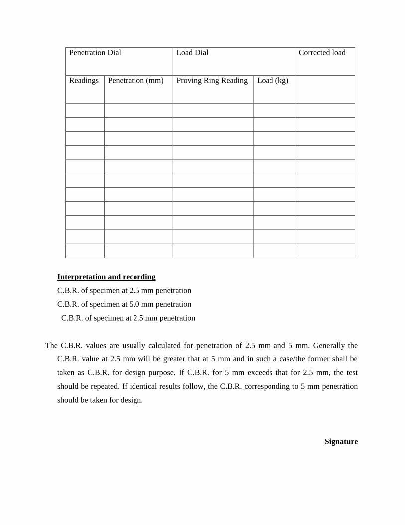
Penetration Dial Load Dial Corrected load
Readings Penetration (mm) Proving Ring Reading
Load (kg)
Interpretation and recording
C.B.R. of specimen at 2.5 mm penetration
C.B.R. of specimen at 5.0 mm penetration
C.B.R. of specimen at 2.5 mm penetration
The C.B.R. values are usually calculated for penetration of 2.5 mm and 5 mm. Generally the
C.B.R. value at 2.5 mm will be greater that at 5 mm and in such a case/the former shall be
taken as C.B.R. for design purpose. If C.B.R. for 5 mm exceeds that for 2.5 mm, the test
should be repeated. If identical results follow, the C.B.R. corresponding to 5 mm penetration
should be taken for design.
Signature


![GG Abd El-Aal and Dahim, eol eophys 215, 4:6 Journal of … … · · 2017-08-17abrasion test, soundness, ... flakiness and elongation indices [3-9]. Flakiness and elongation Index](https://static.documents.pub/doc/80x56/5b06df5a7f8b9ac33f8d6877/gg-abd-el-aal-and-dahim-eol-eophys-215-46-journal-of-2017-08-17abrasion-test.jpg)