Page 1
IRG/WP 14-30639
THE INTERNATIONAL RESEARCH GROUP ON WOOD PROTECTION
Section 3 Wood Protecting Chemicals
Laboratory investigation of fire protection coatings for creosote-
treated timber railroad bridges
Carol A. Clausen, Robert H. White, James P. Wacker, Stan T. Lebow, Mark A. Dietenberger,
Samuel L. Zelinka and Nicole M. Stark
U.S. Forest Service
Forest Products Laboratory
One Gifford Pinchot Drive
Madison, Wisconsin 53726 U.S.A.
Paper prepared for 45th
Annual Meeting
St George, Utah, USA
15 May 2014
Disclaimer
The opinions expressed in this document are those of the author(s) and are not necessarily the opinions or policy
of the IRG Organization.
The use of trade or firm names in this publication is for reader information and does not imply endorsement by
the U.S. Department of Agriculture of any product or service. The Forest Products Laboratory is maintained in
cooperation with the University of Wisconsin. This article was written and prepared by U.S. Government
employees on official time, and it is therefore in the public domain and not subject to copyright.
IRG SECRETARIAT
Box 5609
SE-114 86 Stockholm
Sweden
www.irg-wp.com
Page 2
2
Protective measures from fire for timber railroad bridges
Carol A. Clausen1, Robert H. White
1, James P. Wacker
1, Stan T. Lebow
1, Mark A.
Dietenberger1, Samuel L. Zelinka
1 and Nicole M. Stark
1
1U.S. Forest Products Laboratory, One Gifford Pinchot Drive, Madison, Wisconsin 53726 USA
[email protected] ; [email protected] ; [email protected] ; [email protected] ; [email protected] ;
[email protected] ; [email protected]
ABSTRACT
As the incidence of timber railroad bridge fires increases, so has the need to develop
protective measures to reduce the risk from accidental ignitions primarily caused by hot
metal objects. Of the six barrier treatments evaluated in the laboratory for their ability
to protect timbers from fires sourced with ignition from hot metal objects only one
intumescent coating provided adequate fire protection. The intumescent barrier
treatment also met environmental, performance (e.g. bond durability) and application
criteria set forth in this study. These criteria also dictated the development of a
flammability test, called the hot metal test that is compatible with the fire scenario
specific to this study. The hot metal test evaluates protective materials on creosote-
treated timber against ignition of gases generated by an 1100ᴼC heat source.
Keywords: barrier treatment, fire retardant, intumescent, railroad, crossties, protection,
creosote
1. INTRODUCTION
An increase in frequency of fires in timber railroad bridges has renewed the need to address
fire performance of creosote-treated wood bridge members and investigate options for adding
protective materials to reduce the fire risk from ignitions. The focus of this study was fire
incidents attributed to ignition sources from sparks, hot metal objects (e.g. metal brake
shoes), and maintenance work that is routinely performed on steel rails. Other potential
ignition sources not within the scope of this study include debris accumulation, decay,
proximity of roadside vegetation, wildland fires and arson.
Despite operational improvements to reduce the incidence of sparks and residual hot metal
objects along with efforts to reduce debris and other secondary ignition sources, the incidence
of fire to timber rail bridges is increasing particularly in the hot, dry climates in the west and
southwest United States. In 2011, the 341,181 km of railroad track in use by U.S. railroads
was comprised of approximately 689,974,000 crossties (RTA 2014) with 76,000 railroad
bridges (GAO 2007). There are critical sections of timber bridges, such as the bridge deck
crib, which appear to be prone to fire resulting in hazardous situations for approaching trains,
major disruption of rail traffic, and possible catastrophic losses of life and property.
Page 3
3
There was an active research program in the United States devoted to fire performance of
creosote-treated wood in the mid to late 950’s when the cost of fires on railroads exceeded
$6 million USD (Collister 1963). As early as 1952, Hubert (1952) described the addition of
triaryl phosphate to creosote–petroleum to provide fire protection for fence posts. Coburn
and Morris (1956, 1958) reported on the behavior of proprietary compositions for treated
southern yellow pine when subjected to fire and weathering tests, and developed basic
information regarding the burn characteristics of treated timber. They investigated efforts to
mitigate fires in timber railroad bridges treated with oil-type preservatives resulting from
fuses, brake shoe slivers, brush and tumbleweeds. Gooch et al. (1959) reported on the
addition of triaryl phosphate to creosote-petroleum to address concerns of U.S. railroads on
the potential fire hazard present in trestles made of timbers treated with oil-type
preservatives. They also examined phosphorus-halogen combinations as an option to address
the flaming combustion of the hydrocarbon distillation products in tiers of cribs using a
gasoline ignition source. One conclusion from that study was that large retentions of oil-type
preservatives caused increased fire hazard. Coburn and Morris (1959) investigated the
potential of adding fire-retardant chemicals (i.e. an aromatic ester of phosphoric acid) to the
creosote-petroleum preservative treatment. They noted that creosote and mixed creosote
treatments behaved differently and that the fire performance of the treated wood depended on
the age of the treatment, the retention, and the wood species. They tested the performance of
full-scale replica trestles using dry tumbleweeds as the ignition source. For the
creosote/triphenol phosphate-treated trestles, two years of weathering did not significantly
affect the results. It was noted that the most persistent flaming always occurred in protected
locations where entrapped heat could cause volatile materials to burn above the wood surface
and away from the influence of the phosphate additive.
The fire hazard of wood newly treated with creosote is generally acknowledged in the
literature, but there are conflicting claims on the fire performance of the creosote-treated
wood after some aging or weathering. Indeed, while sparks and hot metal objects are
sufficiently hot enough to quickly ignite creosote-treated wood, without continued external
heat exposure such fires normally self-extinguish with only localized damage after a period
of flaming, smoking and smoldering. Conditions that might allow such a fire to progress to a
more damaging fire include members of smaller dimensions, construction details that allow
re-radiation between burning surfaces, upward flame spread that increases surface areas
exposed to the flames, and sufficient air flow to advance glowing wood to flaming wood.
Dowling (1994) studied the ignition and burning of timber bridges in bushfires. Embers from
wood cribs were used as ignition sources. He concluded that most timber bridges damaged or
destroyed in bushfires are probably ignited by small poles of glowing embers lodging in gaps
or crevices. Ignitions occur in the gaps between deck planks usually at a point above a
crossbeam. He also concluded that in experiments where timber members have been
protected by intumescent paint or fire-retardant solution, the incidence of ignition was
reduced but not eliminated.
Patented technologies (1962, 1975) disclosed fire-retardant creosote comprised of creosote,
tricresylphosphate, chlorinated rubber, antimony tri-chloride and a phosphorus compound.
The last known fire-retardant coating specifically for rail bridges constructed with creosote-
treated wood was developed by the British Columbia Research Council and patented in
Canada. It was first used about 1970, but its use was discontinued around 1993. Recent
efforts pertaining to the fire protective coatings for treated wood in the United States are
Page 4
4
limited to utility poles treated with inorganic water-borne salts or pentachlorophenol. Recent
literature on fire protection of creosote-treated wood is non-existent.
There is an existing American Railway Engineering and Maintenance-of-Way
Association (AREMA 2013) Standard that addresses several of the performance
characteristics of such a coating for these applications. It states “The dry film is
expected to exhibit adhesion, durability, foot traffic, and fire retardancy. The fire
retardancy is evaluated in a fire-test cabinet and also in a fusee test using a 10-minute
fusee. Acceptance criteria for the fire cabinet test required self-extinguishment within
the 30-minute free-burning period and limitations on total weight loss, char depth, char
density, glowing combustion, and integrity of the coating.” There was also an
accelerated weathering component of the Specification. In 2013, there was a motion to
have the Specification removed for lack of use. Ironically, the motion occurred at the
same time the rail industry is experiencing an annual increase in catastrophic economic
losses from rail fires in stringers, crossties, cribs, trestles and associated creosote-
treated rail bridge substructures.
Criteria for barrier treatments have changed since the 950’s to emphasize environmental
safety for use over water. Protective barrier treatments must be suitable for spray application,
durable without the need for frequent re-application, flexible over a wide temperature range,
able to bond to new or weathered creosote-treated wood without the need for surface
cleaning, low cost, and dyed to enable identification of coated crossties and visual inspection
of coated crossties for signs of physical and biological deterioration. There were two
objectives for this study: 1) to develop a flammability test method to simulate ignition
circumstances that lead to large and sustained fires on creosote-treated timbers and 2) to
evaluate barrier coatings on new and weathered creosote-treated timbers for their ability to
primarily reduce flame spread and secondarily, prevent ignition due to various chemical
mechanisms such as volatile blocking, heat insulation, charring, or heat dissipation.
2. EXPERIMENTAL METHODS
2.1 Test Specimens
Creosote treated crossties (i.e. sleepers) were obtained from a railroad company. Crossties
were designated as “new” or “weathered”, cut to varying specimen sizes depending on the
requirement of a specific test method, brush-coated with individual barrier treatments, and
cured for 4 weeks at 70ºC and 50% relative humidity (RH) before initial fire performance
screening in the Schlyter and mass loss calorimeter tests, leach testing and weathering.
Uncoated new and weathered specimens served as controls. For mechanical testing of bond
durability, specimens were brush-coated with two individual barrier treatments, and cured for
2 weeks at approximately 21ºC indoor prior to cyclic loading tests.
2.2 Barrier Treatments
Six barrier treatments were selected for evaluation based on test criteria and product claims:
Concrete-like mixture of sand, ash, magnesium oxide and potassium phosphate
designated GCR
Latex paint augmented with potassium aluminum sulfate, designated ALM
Latex-based intumescent fire retardant (FR) coating designated NT1
Latex-based intumescent FR coating designated NT2
Water based, thin film intumescent FR designated NT3
Page 5
5
Clear penetrating intumescent FR designated CLR
2.3 Leach Resistance
Leach resistance was evaluated using an adaption of American Wood Protection Association
Standard Method E11 (AWPA 2013). Coated and cured specimens (102 by 102 by 38 mm)
were immersed in 7.6 liters of deionized (DI) water for a total of 16 days. The leach water
was replaced after 0.25, 1, 2, 4, 7, 9, 11 and 14 days during the course of the test. Following
leaching, the specimens were reconditioned in preparation for mass loss calorimeter testing.
The effect of leaching was also evaluated by rating the quality of coating adhesion and
estimating the percent of coating area remaining following leaching. Coating adhesion was
evaluated by gently prying at the coating with a putty knife. Quality of adhesion was
assigned ratings ranging from 5 (good) to 1 (poor). Due to the subjective nature of the rating
test, the same person evaluated all specimens for coating adhesion.
2.4 Weathering
Coated specimens (100 mm x 127 mm) were weathered in an Atlas Ci5000 according to
ASTM G155, Cycle 1 for wood materials (ASTM 2010). Cycle 1 stipulates daylight filters,
and a cycle of 102 minutes of light exposure at 63⁰C and 50% RH followed by 18 minutes of
light exposure and water spray. The total exposure time was 2000 hours. After weathering,
specimens were cut to 100 x 100 mm for the mass loss calorimeter test, air-dried and
reconditioned.
2.5 Fire performance tests
2.5.1 Mass Loss calorimeter
The ASTM E2102 standard method for mass loss and ignitability was used to initially screen
treatments and then evaluate leached and weathered specimens (ASTM 2013). The test is
commonly referred to as the mass loss calorimeter test. For this method, a conical electric
heater provided a constant heat flux onto 100 mm by 100 mm test specimens as the mass loss
and heat release rate were recorded for a fixed amount of time (500 seconds). A spark igniter
was placed above the specimen to ignite the combustible gases.
2.5.2 FPL Schlyter test
A burner was placed between two parallel vertical specimens for three minutes, then the
burner was extinguished and the flame height was observed for an additional 3 min (Eickner
1977). Heat release rate calculated from oxygen consumption measurements (Dietenberger
and Boardman 2013) was recorded for the duration of the test. The selected results reported
included the peak heat release rate, the average heat release rate for the first three minutes, for
the one minute after extinguishment of the burner and for the three minutes after
extinguishment of the burner.
2.5.3 Flammability of large timbers
Communications from a railroad company suggested conditions during a fire incident
included ambient temperatures ranging from 27 to 38°C, constant 16 km/h wind flowing
horizontally to represent ambient wind flow across a rail bridge deck and an overhead wind
speed of 40-48 km/h to represent “fanning” from 25-30 trains passing daily while travelling
at 97 km/h, resulting in 1 minute of fanning at intervals of 20 minutes. Exploratory non-
standard tests evaluated conditions of flammability specific to a railroad fire scenario from
hot metal objects. A steel wafer (25 x 13 x 13 mm) heated to temperatures ranging from 427
to 649°C was placed in a groove, corner or crevice of individual pieces of creosoted-treated
Page 6
6
wood. At these lower temperatures, there was mostly smoke with small flaming. Placing a
pilot flame in the smoke resulted in a flame developing across the whole specimen. The
creosote vapors contributed to the overall flaming combustion. Steel wafers at 1100°C
resulted in almost immediate ignition upon surface contact with creosote wood. Visual
observations of the flame patterns supported the observation that the creosote was a
significant factor in both continued flaming and spread of flames beyond that of untreated
wood.
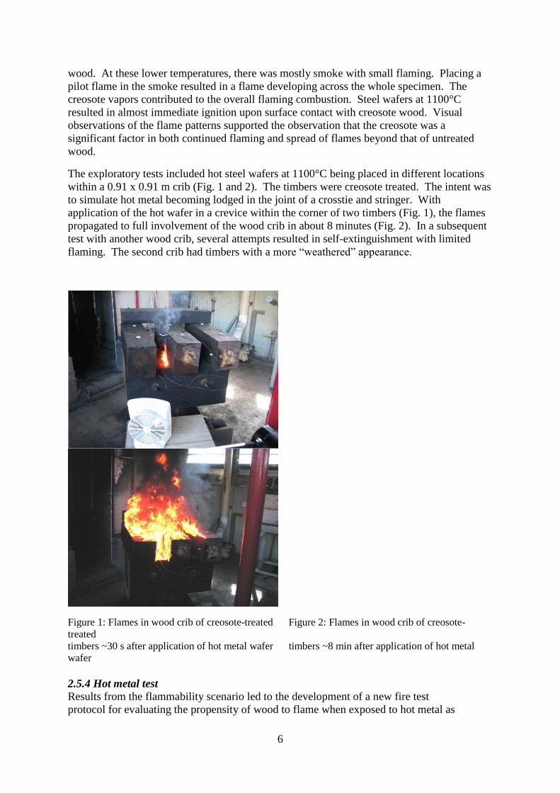
The exploratory tests included hot steel wafers at 1100°C being placed in different locations
within a 0.91 x 0.91 m crib (Fig. 1 and 2). The timbers were creosote treated. The intent was
to simulate hot metal becoming lodged in the joint of a crosstie and stringer. With
application of the hot wafer in a crevice within the corner of two timbers (Fig. 1), the flames
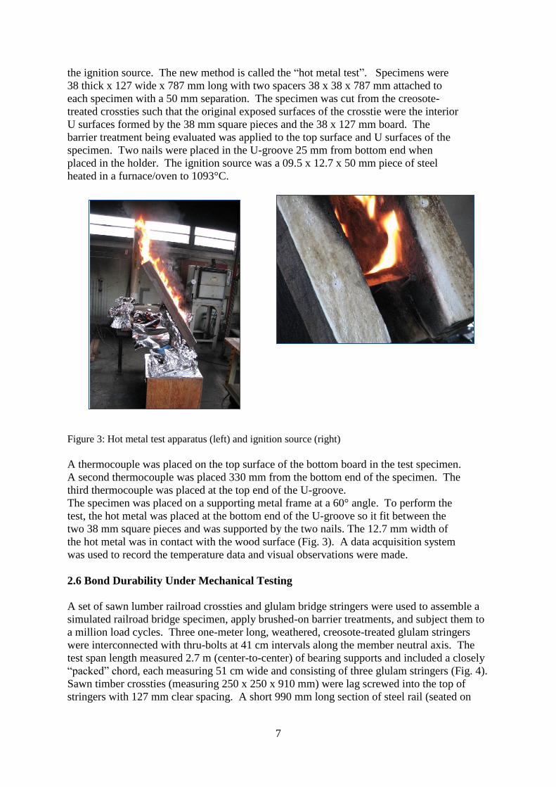
propagated to full involvement of the wood crib in about 8 minutes (Fig. 2). In a subsequent
test with another wood crib, several attempts resulted in self-extinguishment with limited
flaming. The second crib had timbers with a more “weathered” appearance.
Figure 1: Flames in wood crib of creosote-treated Figure 2: Flames in wood crib of creosote-
treated
timbers ~30 s after application of hot metal wafer timbers ~8 min after application of hot metal
wafer
2.5.4 Hot metal test
Results from the flammability scenario led to the development of a new fire test
protocol for evaluating the propensity of wood to flame when exposed to hot metal as
Page 7
7
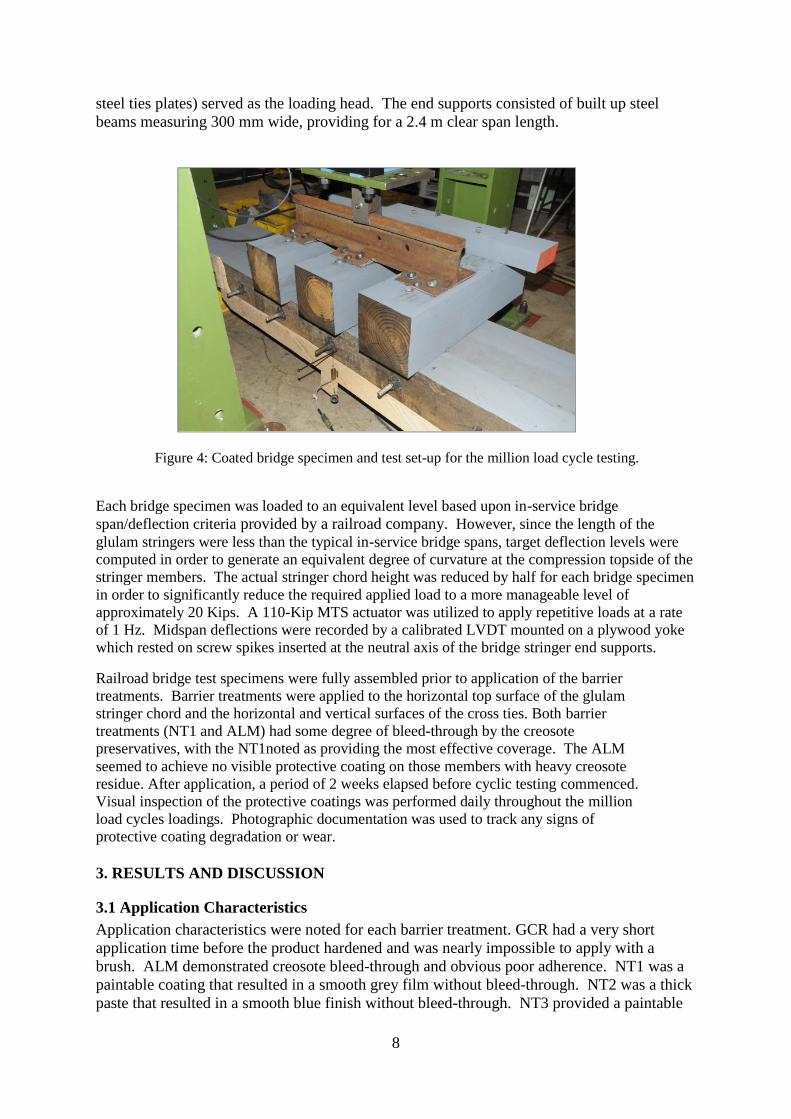
the ignition source. The new method is called the “hot metal test”. Specimens were
38 thick x 127 wide x 787 mm long with two spacers 38 x 38 x 787 mm attached to
each specimen with a 50 mm separation. The specimen was cut from the creosote-
treated crossties such that the original exposed surfaces of the crosstie were the interior
U surfaces formed by the 38 mm square pieces and the 38 x 127 mm board. The
barrier treatment being evaluated was applied to the top surface and U surfaces of the
specimen. Two nails were placed in the U-groove 25 mm from bottom end when
placed in the holder. The ignition source was a 09.5 x 12.7 x 50 mm piece of steel
heated in a furnace/oven to 1093°C.
Figure 3: Hot metal test apparatus (left) and ignition source (right)
A thermocouple was placed on the top surface of the bottom board in the test specimen.
A second thermocouple was placed 330 mm from the bottom end of the specimen. The
third thermocouple was placed at the top end of the U-groove.
The specimen was placed on a supporting metal frame at a 60° angle. To perform the
test, the hot metal was placed at the bottom end of the U-groove so it fit between the
two 38 mm square pieces and was supported by the two nails. The 12.7 mm width of
the hot metal was in contact with the wood surface (Fig. 3). A data acquisition system
was used to record the temperature data and visual observations were made.
2.6 Bond Durability Under Mechanical Testing
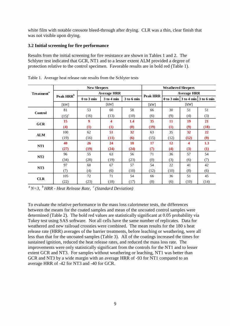
A set of sawn lumber railroad crossties and glulam bridge stringers were used to assemble a
simulated railroad bridge specimen, apply brushed-on barrier treatments, and subject them to
a million load cycles. Three one-meter long, weathered, creosote-treated glulam stringers
were interconnected with thru-bolts at 41 cm intervals along the member neutral axis. The
test span length measured 2.7 m (center-to-center) of bearing supports and included a closely
“packed” chord, each measuring 51 cm wide and consisting of three glulam stringers (Fig. 4).
Sawn timber crossties (measuring 250 x 250 x 910 mm) were lag screwed into the top of
stringers with 127 mm clear spacing. A short 990 mm long section of steel rail (seated on
Page 8
8
steel ties plates) served as the loading head. The end supports consisted of built up steel
beams measuring 300 mm wide, providing for a 2.4 m clear span length.
Figure 4: Coated bridge specimen and test set-up for the million load cycle testing.
Each bridge specimen was loaded to an equivalent level based upon in-service bridge
span/deflection criteria provided by a railroad company. However, since the length of the
glulam stringers were less than the typical in-service bridge spans, target deflection levels were
computed in order to generate an equivalent degree of curvature at the compression topside of the
stringer members. The actual stringer chord height was reduced by half for each bridge specimen
in order to significantly reduce the required applied load to a more manageable level of
approximately 20 Kips. A 110-Kip MTS actuator was utilized to apply repetitive loads at a rate
of 1 Hz. Midspan deflections were recorded by a calibrated LVDT mounted on a plywood yoke
which rested on screw spikes inserted at the neutral axis of the bridge stringer end supports.
Railroad bridge test specimens were fully assembled prior to application of the barrier
treatments. Barrier treatments were applied to the horizontal top surface of the glulam
stringer chord and the horizontal and vertical surfaces of the cross ties. Both barrier
treatments (NT1 and ALM) had some degree of bleed-through by the creosote
preservatives, with the NT1noted as providing the most effective coverage. The ALM
seemed to achieve no visible protective coating on those members with heavy creosote
residue. After application, a period of 2 weeks elapsed before cyclic testing commenced.
Visual inspection of the protective coatings was performed daily throughout the million
load cycles loadings. Photographic documentation was used to track any signs of
protective coating degradation or wear.
3. RESULTS AND DISCUSSION
3.1 Application Characteristics
Application characteristics were noted for each barrier treatment. GCR had a very short
application time before the product hardened and was nearly impossible to apply with a
brush. ALM demonstrated creosote bleed-through and obvious poor adherence. NT1 was a
paintable coating that resulted in a smooth grey film without bleed-through. NT2 was a thick
paste that resulted in a smooth blue finish without bleed-through. NT3 provided a paintable
Page 9
9
white film with notable creosote bleed-through after drying. CLR was a thin, clear finish that
was not visible upon drying.
3.2 Initial screening for fire performance
Results from the initial screening for fire resistance are shown in Tables 1 and 2. The
Schlyter test indicated that GCR, NT1 and to a lesser extent ALM provided a degree of
protection relative to the control specimen. Favorable results are in bold red (Table 1).
Table 1. Average heat release rate results from the Schlyter tests
0 to 3 min 3 to 4 min 3 to 6 min 0 to 3 min 3 to 4 min 3 to 6 min
[kW] [kW]
81 53 60 58 66 30 51 51
(15)c (16) (13) (10) (6) (9) (4) (3)
15 9 4 1.4 35 11 19 21
(4) (1) (1) (0) (19) (1) (9) (18)
100 62 51 32 63 35 32 22
(19) (16) (11) (6) (15) (12) (12) (9)
40 26 24 18 17 12 4 1.3
(27) (19) (24) (24) (7) (4) (3) (1)
96 55 63 56 71 36 57 54
(34) (28) (19) (23) (0) (3) (6) (7)
97 60 67 57 54 22 41 42
(7) (4) (6) (10) (12) (10) (8) (6)
105 72 71 54 66 36 51 45
(22) (23) (18) (17) (8) (6) (10) (14)
aN=3,
bHRR - Heat Release Rate,
c(Standard Deviation)
ALM
NT2
CLR
GCR
NT1
NT3
Treatmenta
New Sleepers Weathered Sleepers
Peak HRRb Peak HRR
Control
Average HRR Average HRR
[kW] [kW]
To evaluate the relative performance in the mass loss calorimeter tests, the differences
between the means for the coated samples and mean of the uncoated control samples were
determined (Table 2). The bold red values are statistically significant at 0.05 probability via
Tukey test using SAS software. Not all cells have the same number of replicates. Data for
weathered and new railroad crossties were combined. The mean results for the 180 s heat
release rate (HRR) averages of the barrier treatments, before leaching or weathering, were all
less than that for the uncoated samples (Table 3). All of the coatings increased the times for
sustained ignition, reduced the heat release rates, and reduced the mass loss rate. The
improvements were only statistically significant from the controls for the NT1 and to lesser
extent GCR and NT3. For samples without weathering or leaching, NT1 was better than
GCR and NT3 by a wide margin with an average HRR of -93 for NT1 compared to an
average HRR of -42 for NT3 and -40 for GCR.
Page 10
10
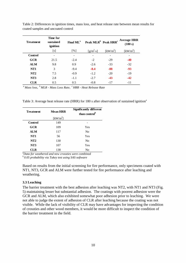
Table 2: Differences in ignition times, mass loss, and heat release rate between mean results for
coated samples and uncoated control
Treatment
Time for
sustained
ignition
Final MLa
Peak MLRb
Peak HRRc Average HRR
(180 s)
[s] [%] [g/m2-s] [kW/m
2] [kW/m
2]
Control - - - - -
GCR 21.5 -2.4 -2 -29 -40
ALM 9.8 0.9 -2.6 -33 -32
NT1 3 -9.4 -8.4 -88 -93
NT2 7.5 -0.9 -1.2 -20 -19
NT3 2.8 -1.1 -2.7 -43 -42
CLR 0.5 0.5 -0.8 -17 -11aMass loss,
bMLR - Mass Loss Rate,
cHRR - Heat Release Rate
Table 3: Average heat release rate (HRR) for 180 s after observation of sustained ignition
a
Treatment Mean HRRSignificantly different
than controlb
[kW/m2]
Control 149 -
GCR 109 Yes
ALM 117 No
NT1 56 Yes
NT2 130 No
NT3 107 Yes
CLR 138 No aData for weathered and new crossties were combined
b 0.05 probability via Tukey test using SAS software
Based on results from the initial screening for fire performance, only specimens coated with
NT1, NT3, GCR and ALM were further tested for fire performance after leaching and
weathering.
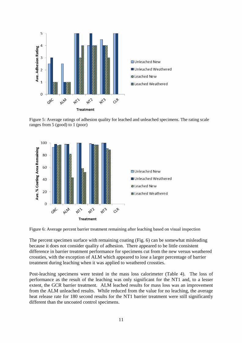
3.3 Leaching
The barrier treatment with the best adhesion after leaching was NT2, with NT1 and NT3 (Fig.
5) maintaining lesser but substantial adhesion. The coatings with poorest adhesion were the
GCR and ALM, which also exhibited somewhat poor adhesion prior to leaching. We were
not able to judge the extent of adhesion of CLR after leaching because the coating was not
visible. While the lack of visibility of CLR may have advantages for inspecting the condition
of crossties and other wood members, it would be more difficult to inspect the condition of
the barrier treatment in the field.
Page 11
11
Figure 5: Average ratings of adhesion quality for leached and unleached specimens. The rating scale
ranges from 5 (good) to 1 (poor)
Figure 6: Average percent barrier treatment remaining after leaching based on visual inspection
The percent specimen surface with remaining coating (Fig. 6) can be somewhat misleading
because it does not consider quality of adhesion. There appeared to be little consistent
difference in barrier treatment performance for specimens cut from the new versus weathered
crossties, with the exception of ALM which appeared to lose a larger percentage of barrier
treatment during leaching when it was applied to weathered crossties.
Post-leaching specimens were tested in the mass loss calorimeter (Table 4). The loss of
performance as the result of the leaching was only significant for the NT1 and, to a lesser
extent, the GCR barrier treatment. ALM leached results for mass loss was an improvement
from the ALM unleached results. While reduced from the value for no leaching, the average
heat release rate for 180 second results for the NT1 barrier treatment were still significantly
different than the uncoated control specimens.
Page 12
12
Table 4. Differences between mean results for barrier treatments with and without leaching exposure
TreatmentTime for sustained
ignitionFinal ML
aPeak MLR
bPeak HRR
c Average HRR
(180 s)
[s] [%] [g/m2-s] [kW/m
2] [kW/m
2]
GCR -29.3 3.98 0.9 18.3 10.1
ALM 3.2 2.76 1.15 26.5 17.6
NT1 -1.6 -7.3 -6.92 -49.8 -55.7
NT3 -0.8 -0.45 -2.27 -10.0 -11.5aML -
Mass Loss,
bMLR - Mass Loss Rate,
cHRR - Heat Release Rate
Bold red values are 0.05 probability via Tukey test using SAS software; data for weathered and new
sleepers were combined
3.3 Weathering
Observations during the first two weeks of weathering noted that a significant amount of
flaked coating could be seen in the bottom of the weathering chamber. Upon completion of
the 2000 hr weathering cycle, specimens were air dried, and reconditioned at 70ºC and 50%
RH before fire performance testing.
In the mass loss calorimeter tests (Table 5), the means for NT1 after weathering were higher
(i.e. worse) and the difference was statistically significant than the original NT1 and also
higher, but not statistically different than the control. The means for the other coatings were
lower than the control but not statistically different. While not statistically significant, the
means also increased (compared with non-weathered samples) for the NT3, NT2, and GCR
samples. Of the coated samples, GCR and ALM had the lowest means.
No barrier treatment after weathering had means that could be considered better than the
control based on statistical analysis (Table 6). The means for fire performance for NT1 after
weathering were worse than the coated samples that were not weathered. The means for the
weathered NT1 coated samples were also higher, but not statistically different, than uncoated
control samples. The means for the other coatings after weathering were not statistically
different than the respective unweathered samples.
Table 5. Average heat release rate (HRR) for 180 s after observation of ignition for weathered
samples
Treatment Mean HRR Significantly different than controla
[kW/m2]
Controlb 149 -
GCR 118 No
ALM 123 No
NT1 153 No
NT3 142 No
a0.05 probability via Tukey test using SAS software; data for weathered and new sleepers were combined
bControl samples were not weathered
Page 13
13
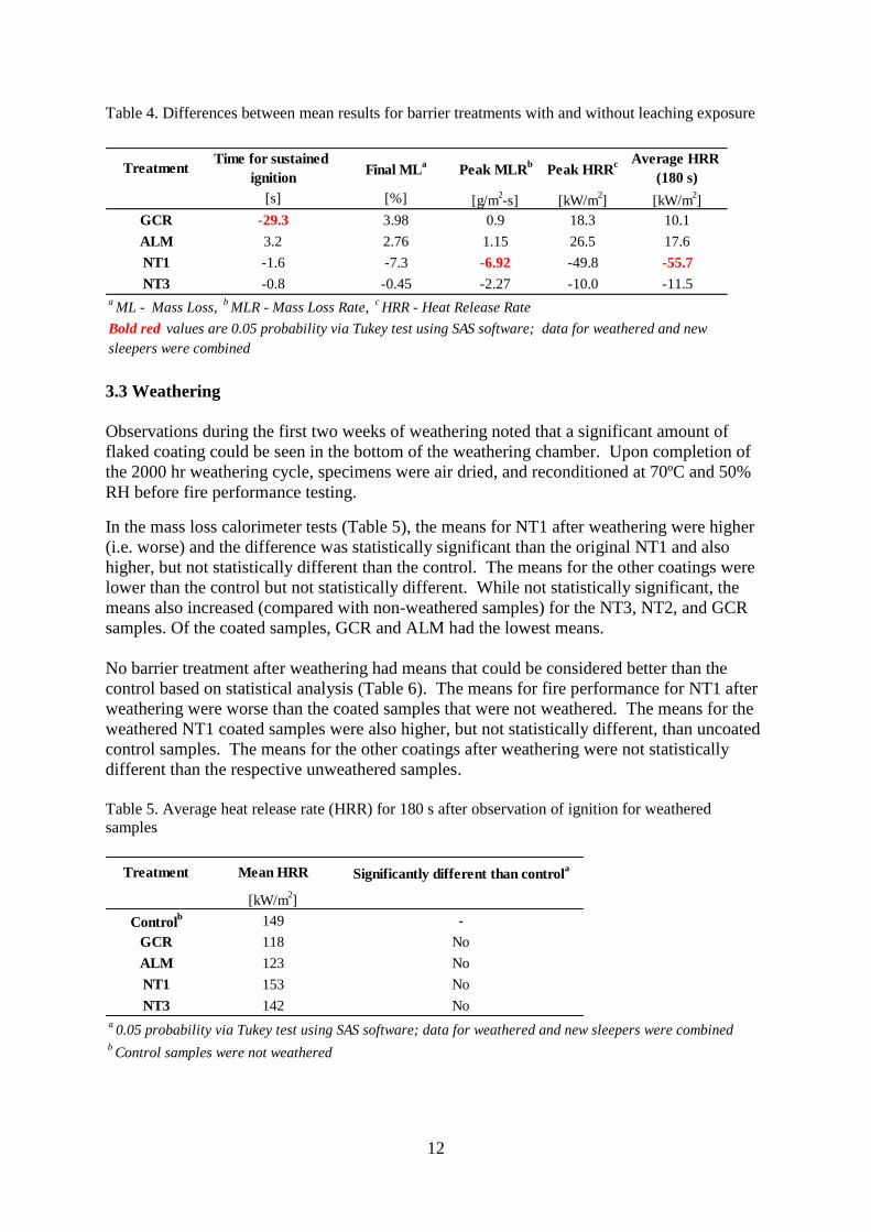
Table 6. Difference between mean results for coatings with and without weathering exposure
TreatmentTime for sustained
ignitionFinal Mass Loss Peak MLR
aPeak HRR
b Average HRR
(180 s)
[s] [%] [g/m2-s] [kW/m
2] [kW/m
2]
GCR 15.5 4.2 1.4 9.8 -9.5
ALM 5.2 7.5 -0.7 -21.2 -24.6
NT1 -1.6 -5.9 -7.5 -78.6 -97.2
NT3 1.3 4.6 -1.5 -33.1 -40.5
aMLR - Mass Loss Rate,
bHRR - Heat Release Rate
Bold red values are 0.05 probability via Tukey test using SAS software; data for weathered and new
sleepers were combined
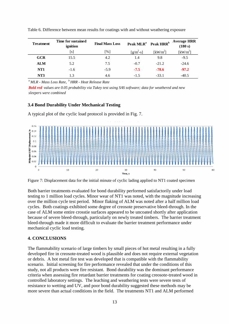
3.4 Bond Durability Under Mechanical Testing
A typical plot of the cyclic load protocol is provided in Fig. 7.
Figure 7: Displacement data for the initial minute of cyclic lading applied to NT1 coated specimen
Both barrier treatments evaluated for bond durability performed satisfactorily under load
testing to 1 million load cycles. Minor wear of NT1 was noted, with the magnitude increasing
over the million cycle test period. Minor flaking of ALM was noted after a half million load
cycles. Both coatings exhibited some degree of creosote preservative bleed-through. In the
case of ALM some entire crosstie surfaces appeared to be uncoated shortly after application
because of severe bleed-through, particularly on newly treated timbers. The barrier treatment
bleed-through made it more difficult to evaluate the barrier treatment performance under
mechanical cyclic load testing.
4. CONCLUSIONS
The flammability scenario of large timbers by small pieces of hot metal resulting in a fully
developed fire in creosote-treated wood is plausible and does not require external vegetation
or debris. A hot metal fire test was developed that is compatible with the flammability
scenario. Initial screening for fire performance revealed that under the conditions of this
study, not all products were fire resistant. Bond durability was the dominant performance
criteria when assessing fire retardant barrier treatments for coating creosote-treated wood in
controlled laboratory settings. The leaching and weathering tests were severe tests of
resistance to wetting and UV, and poor bond durability suggested these methods may be
more severe than actual conditions in the field. The treatments NT1 and ALM performed
Page 14
14
satisfactorily under mechanical load testing for 1 million cycles. Field performance of the
barrier treatment with the best overall fire performance and adhesion, i.e. NT1, is warranted
and the durability of the intumescent performance should be verified after some period of
field exposure, e.g. 1 year. Additional research is needed to develop pressure treatments for
crossties and bridge components that will provide reliable protection against decay and fire.
Acknowledgement
The authors thank the staff at Forest Products Laboratory, Comazel Caldwell, Charles
Boardman, Keith Bourne, Laura Hasburgh, Steve Halverson, Marc Joyal, Marshall
Begel, Dwight McDonald, James Bridwell, Steve Schmieding, Joseph Balczewski, and
Phil Walsh for their technical assistance.
5. REFERENCES
American Railway Engineering and Maintenance-of-Way Association (AREMA) Manual for
Railway Engineering (2013): Recommendations for Fire-Retardant Coating for Creosoted
Wood, Chapter 7, Timber Structures. Vol. 89, (1963), R(2008) p. 7–1–20.
ASTM International (2010): Standard practice for operating xenon arc light exposure of non-
metallic materials. G155–5a. In: Annual Book of ASTM Standards, Vol. 14.04. pp. 1303–
1322. West Conshohocken, Pennsylvania.
ASTM International (2013): Standard test method for measurement of mass loss and
ignitability for screening purposes using a conical radiant heater. E2102–13. In: Annual Book
of ASTM Standards, Vol. 14.04. pp. 658–668. West Conshohocken, Pennsylvania.
American Wood Protection Association Standards (AWPA) (2013): Standard method for
accelerated evaluation of preservative leaching. E11–12. In: Annual Book of AWPA
Standards, Birmingham, Alabama.
Coburn, S K, Morris, K J (1956): Some factors to consider when formulating fire-retardant
coatings for treated timber. Official Digest, Federation of Paint and Varnish Production
Clubs 28:1245–1260.
Coburn, S K, Morris, K J (1958): Some effects of creosote solutions on the flammability of
southern pine. In: American Wood-Preservers’ Association, Washington, D.C. 54:78–97.
Coburn, S K, Morris, K J (1959): Effect of a proprietary fire-inhibiting substance on the
flammability of treated southern yellow pine. In: American Wood-Preservers’ Association
Proceedings, Washington, D.C. 59: 70–88.
Collister, L C (1963): Fire-retarding treatments on the Santa Fe. In: American Wood-
Preservers’ Association Proceedings, Washington, D.C. 59: 92–98.
Dietenberger, M A, Boardman, C R (2013): HRR Upgrade to mass loss calorimeter and
modified Schlyter test for FR Wood. In: Proceedings of the Fire and Materials 2013
Conference, San Francisco, 28–30 January 2013. pp. 251–263.
Page 15
15
Dowling, V P (1994): Ignition of timber bridges in bushfires. Fire Safety Journal 22:145–
168.
Eickner, H W (1977): Surface flammability measurements for building materials and related
products. In: Treatise on Analytical Chemistry, Part 3, Vol. 4, ed. I.M. Kolthoff, P.J. Elving,
F.H. Stross. John Wiley & Sons, New York.
Government Accountability Office (GAO) (2007): Railroad Bridges and Tunnels: Federal
Role in Providing Safety Oversight and Freight Infrastructure Investment Could Be Better
Targeted. GAO–07–770. Washington, D.C.: August 2007.
Gooch R M, Kenaga D L, Tobey H M (1959): Fire retardants for wood treated with oil-type
preservatives. Forest Products Journal 9(10): 325–329.
Hubert, E E (1952): The use of fire retardants in a penta fence post preservative. Research
Note 2, Forest Wildland and Range Experiment Station, University of Idaho.
Kemp, W E (1975): Wood treating solution containing creosote and antimony. United States
Patent #US 3888774 A.
Lowell, B (1962): Fire retardant creosote composition. United States Patent #US 3031374 A.
Railroad Tie Association (RTA) www.rta.org/faqs-main, accessed January 2014.