31
Laminar Flow Rodney Bajnath, Beverly Beasley, Mike Cavanaugh AOE 4124 March 29, 2004
| Date post: | 15-Dec-2015 |
| Category: |
Documents |
| Upload: | ally-welton |
| View: | 220 times |
| Download: | 1 times |
Laminar Flow
Rodney Bajnath, Beverly Beasley, Mike Cavanaugh
AOE 4124
March 29, 2004
Introduction
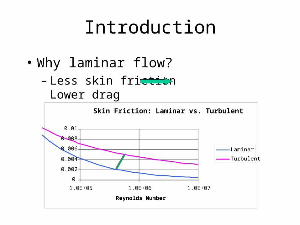
• Why laminar flow?– Less skin friction Lower drag
Skin Friction: Laminar vs. Turbulent
0
0.002
0.004
0.006
0.008
0.01
1.0E+05 1.0E+06 1.0E+07
Reynolds Number
CfLaminar
Turbulent
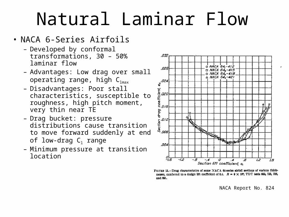
Natural Laminar Flow• NACA 6-Series Airfoils
– Developed by conformal transformations, 30 – 50% laminar flow
– Advantages: Low drag over small operating range, high Clmax
– Disadvantages: Poor stall characteristics, susceptible to roughness, high pitch moment, very thin near TE
– Drag bucket: pressure distributions cause transition to move forward suddenly at end of low-drag Cl range
– Minimum pressure at transition location
NACA Report No. 824

Natural Laminar Flow
• NACA 6A-Series– 30 - 50% laminar flow– Eliminated TE cusp– Essentially same lift and
drag characteristics as 6-series
NACA Report No. 903
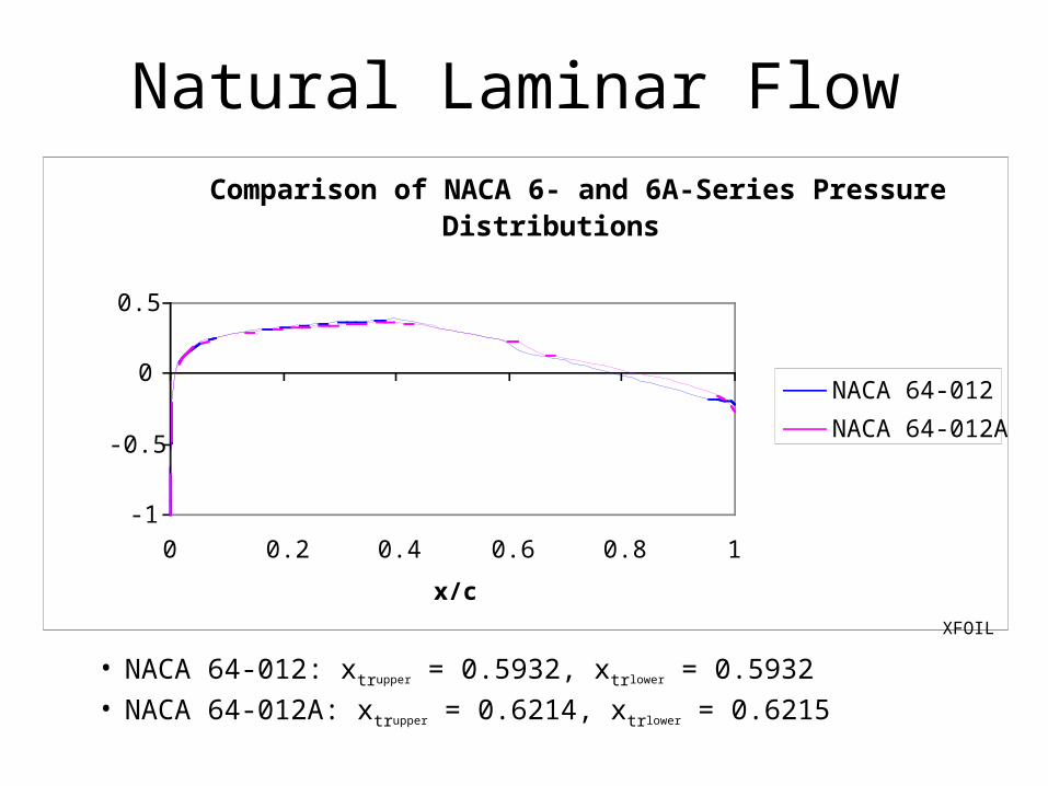
Comparison of NACA 6- and 6A-Series Pressure Distributions
-1
-0.5
0
0.5
0 0.2 0.4 0.6 0.8 1
x/c
CpNACA 64-012
NACA 64-012A
Natural Laminar Flow
• NACA 64-012: xtrupper = 0.5932, xtrlower = 0.5932• NACA 64-012A: xtrupper = 0.6214, xtrlower = 0.6215
XFOIL
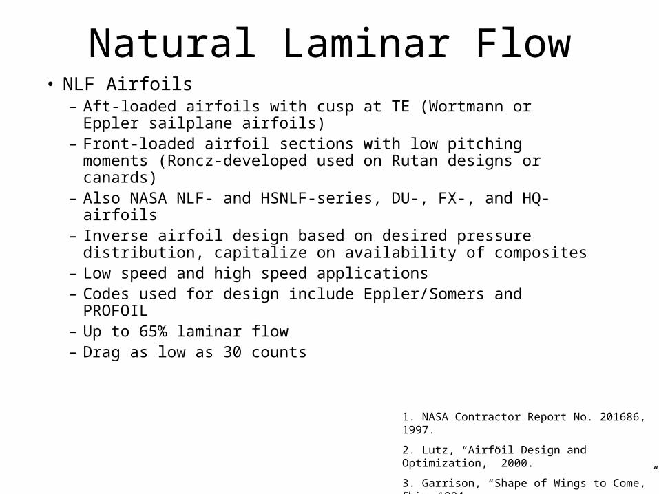
Natural Laminar Flow• NLF Airfoils
– Aft-loaded airfoils with cusp at TE (Wortmann or Eppler sailplane airfoils)
– Front-loaded airfoil sections with low pitching moments (Roncz-developed used on Rutan designs or canards)
– Also NASA NLF- and HSNLF-series, DU-, FX-, and HQ- airfoils– Inverse airfoil design based on desired pressure distribution,
capitalize on availability of composites– Low speed and high speed applications– Codes used for design include Eppler/Somers and PROFOIL– Up to 65% laminar flow– Drag as low as 30 counts
1. NASA Contractor Report No. 201686, 1997.
2. Lutz, “Airfoil Design and Optimization,” 2000.
3. Garrison, “Shape of Wings to Come,” Flying 1984.
4. NASA Technical Memorandum 85788, 1984.

Natural Laminar Flow: Case Study
• SHM-1 Airfoil for the Honda Jet• Lightweight business jet, airfoil inversely designed,
tested in low-speed and transonic wind tunnels, and flight tested
• Designed to exactly match HJ requirements – High drag-divergence Mach number– Small nose-down pitching moment– Low drag for high cruise efficiency– High Clmax
– Docile stall characteristics– Insensitivity to LE contamination
Fujino et al, “Natural-Laminar-Flow Airfoil Development for the Honda Jet.”

Natural Laminar Flow: Case Study (Continued)
• Requirements– Clmax = 1.6 for Re = 4.8x10⁶, M = 0.134
– Loss of Cl less than 7% due to contamination
– Cm > -0.04 at Cl = 0.38, Re = 7.93x10⁶, M = 0.7
– Airfoil thickness = 15%
– MDD > 0.70 at Cl = 0.38
– Low drag at cruiseFujino et al, “Natural-Laminar-Flow Airfoil Development for the Honda Jet.”
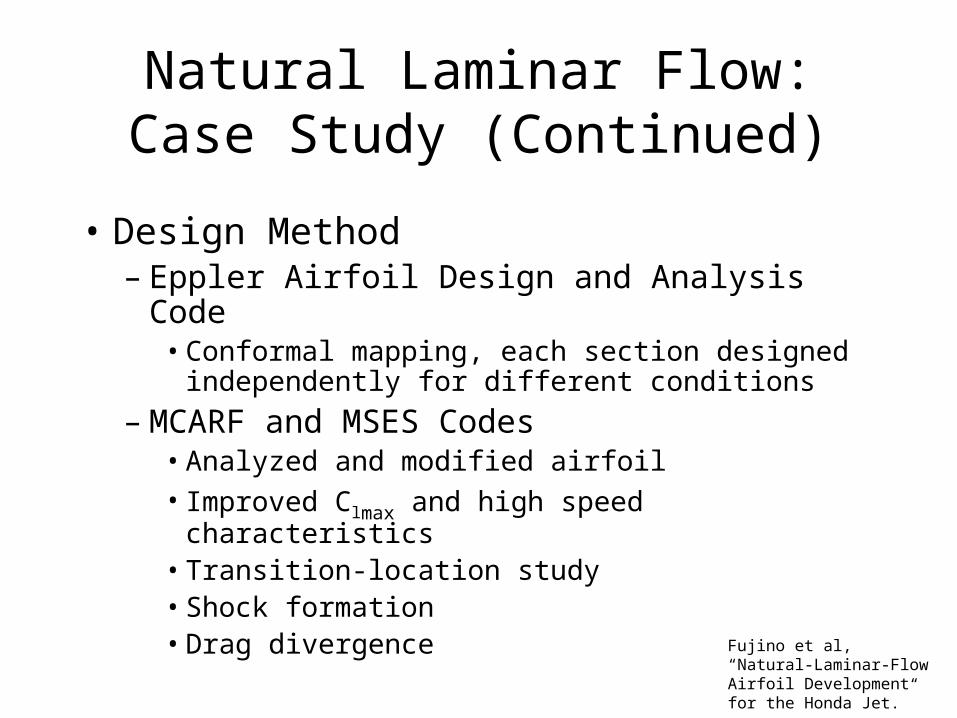
Natural Laminar Flow: Case Study (Continued)
• Design Method– Eppler Airfoil Design and Analysis Code
• Conformal mapping, each section designed independently for different conditions
– MCARF and MSES Codes• Analyzed and modified airfoil• Improved Clmax and high speed characteristics• Transition-location study• Shock formation• Drag divergence Fujino et al, “Natural-Laminar-
Flow Airfoil Development for the Honda Jet.”

Natural Laminar Flow: Case Study (Continued)
• Resulting SHM-1 airfoil– Favorable pressure gradient to 42%c upper
surface, 63%c lower surface– Concave pressure recovery (compromise
between Clmax, Cm, and MDD)
– LE such that at high α, transition near LE (roughness sensitivity)
– Short, shallow separation near TE for Cm
Fujino et al, “Natural-Laminar-Flow Airfoil Development for the Honda Jet.”
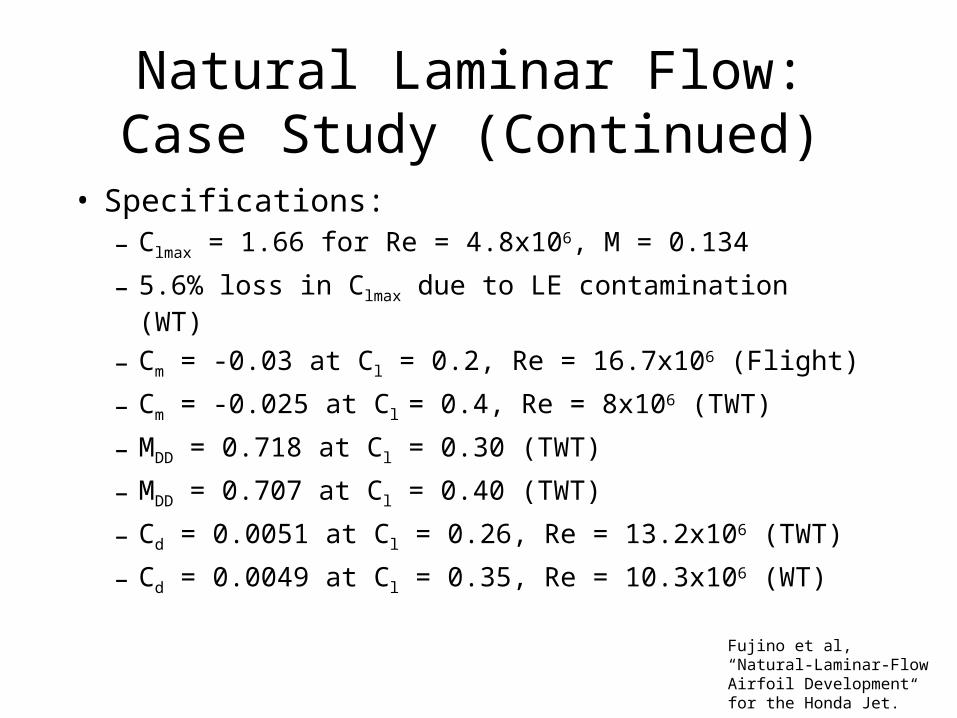
Natural Laminar Flow: Case Study (Continued)
• Specifications:– Clmax = 1.66 for Re = 4.8x10⁶, M = 0.134
– 5.6% loss in Clmax due to LE contamination (WT)
– Cm = -0.03 at Cl = 0.2, Re = 16.7x10⁶ (Flight)
– Cm = -0.025 at Cl = 0.4, Re = 8x10⁶ (TWT)
– MDD = 0.718 at Cl = 0.30 (TWT)
– MDD = 0.707 at Cl = 0.40 (TWT)
– Cd = 0.0051 at Cl = 0.26, Re = 13.2x10⁶ (TWT)
– Cd = 0.0049 at Cl = 0.35, Re = 10.3x10⁶ (WT)
Fujino et al, “Natural-Laminar-Flow Airfoil Development for the Honda Jet.”
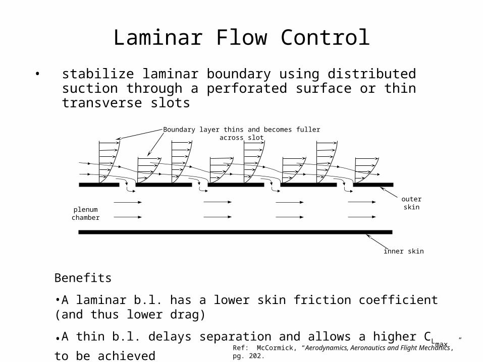
Laminar Flow Control
• stabilize laminar boundary using distributed suction through a perforated surface or thin transverse slots
plenum chamber
outer skin
inner skin
Boundary layer thins and becomes fuller across slot
Benefits
•A laminar b.l. has a lower skin friction coefficient (and thus lower drag)
•A thin b.l. delays separation and allows a higher CLmax to be achieved
Ref: McCormick, “Aerodynamics, Aeronautics and Flight Mechanics,” pg. 202.

Notable Laminar Flow Control Flight Test ProgramsDate Aircraft Test Configuration LF Result Comments
1940 Douglas B-18
(NACA)
2-engine prop
bomber
NACA 35-215
10’x17’ wing glove section
suction slots first 45% chord
LF to 45% chord
(LF to min Cp)
RC = 30x106
Engine/prop noise effected LF
surface quality issues
1955 Vampire
(RAE)
single engine jet
upper surface wing glove
suction - porous surface
full chord suction
full chord LF
M~0.7 / RC=30x106
Monel/Nylon cloth
0.007” perforations
1954-
1957
F-94 (Northrup/USAF)
jet fighter
NACA 63-213
upper surface wing glove
suction – 12, 69, 81 slots
Full chord LF
0.6 < M < 0.7
RC = 36x106
at Mlocal>1.09 shocks caused loss of LF
1963-1965
X-21 (Northrup/USAF)
jet bomber
30° sweep
new LF wings for program
suction through nearly full span slots – both wings
full chord LF
RC = 47x106
effects of sweep on LF encountered
1985-1986
JetStar
(NASA)
4-engine business jet
two leading edge gloves
Lockheed – slot suction & liquid leading edge protection
McDD – perforated skin & and bug deflector
LF maintained to front spar through
two years of simulated airline
service
no special maintenance required lost LF in clouds &
during icing
LE protection effective
Ref: Applied Aerodynamic Drag Reduction Short Course Notes, Williamsburg,VA 1990.

Why Does LFC Reduces Drag?• removes turbulent boundary layer
XFOIL output

Why Does LFC Reduce Drag?• turbulent boundary layer has a higher skin friction coefficient
XFOIL Output
upper surface
lower surface

Why Does LFC Increases CLMAX?
• move boundary layer separation point aft
x - ft
-1.0 -0.8 -0.6 -0.4 -0.2 0.0 0.2 0.4 0.6 0.8 1.0
Cp
0.0
0.2
0.4
0.6
0.8
1.0
-1.0(2196)
-0.25(759)
-0.0625(276)
-0.015625(108)
m = 1/4
x0 = 1.0 ft
x0 = 0.25 ft
x0 = 0.0625 ft
x0 = 0.015625 ftReynolds Number = 6x10⁶
Ref: A.M.O. Smith, “High Lift Aerodynamics,” Journal of Aircraft, Vol. 12, No. 6, June 1975

Raspet Flight Research Laboratory Powered Lift Aircraft
Piper L-21 Super Cub (1954)
•distributed suction - perforated skins
•CLMAX = 2.16 →4.0
•2.0 Hp required for suction(Ref: Joseph Cornish, “A Summary of the Present State of the Art in Low Speed Aerodynamics,” MSU Aerophysics Dept., 1963.)
Cessna L-19 Birddog (1956)
•distributed suction - perforated skins
•CLMAX = 2.5 →5.0
•7.0 Hp required for suction(Ref: Joseph Cornish, “A Summary of the Present State of the Art in Low Speed Aerodynamics,” MSU Aerophysics Dept., 1963.)
Photographs Courtesy of the Raspet Flight Research Laboratory

Suction Power Required for 23012 Cruise Condition
leading edge x (ft) trailing edge
0.0 0.5 1.0 1.5 2.0 2.5 3.0 3.5 4.0
required suction velocity - v
w (ft/s)
-0.4
-0.3
-0.2
-0.1
0.0
NACA 23012cruise CL = 0.4
10,000 ft.180 kts (303.6 ft/s)
adverse pressure gradient
dx
dUv e
w υ−−= 18.2
•Suction velocity required to maintain incipient separation of the laminar b.l and prevent flow reversal is given by:
Joseph Schetz, “Boundary Layer Analysis,” Equation (2-37)
0.035”
0.0025” dia
45” chord
12
” sp
an45” x 12” grid – 439,470 holes
Preq = .00318 Hp / foot of span*
*assumes:•use highest vw and Δp in calculation•discharge coefficient of 0.5•pump efficiency of 60%

Laminar Flow Control Approaches
leading edge x (ft) trailing edge
0.0 0.5 1.0 1.5 2.0 2.5 3.0 3.5 4.0
required suction velocity - v
w (ft/s)
-0.4
-0.3
-0.2
-0.1
0.0
NACA 23012cruise CL = 0.4
10,000 ft.180 kts (303.6 ft/s)
adverse pressure gradient
1). Leading Edge Protection
2). Distributed Suction (perforated skin or slots)
3). Hybrid Laminar Flow ControlRef: Applied Aerodynamic Drag Reduction Short Course Notes, …….Williamsburg,VA 1990.

Laminar Flow Control Problems/Obstacles
• Sweep– Attachment line contamination (fuselage boundary layer)
– Crossflow instabilities (boundary layer crossflow vortices)
• Manufacturing tolerances / structure– Steps, gaps, waviness
– Structural deformations in flight
• System complexity– Ducting and plenums
– Hole quantity and individual hole finish
• Surface contamination– Bypass transition (3-D roughness)
– Insects, dirt, erosion, rain, ice crystals
Ref: Applied Aerodynamic Drag Reduction Short Course Notes, Williamsburg,VA 1990.
Ref: Mark Drela, “XFOIL 6.9 User Guide”, MIT Aero & Astro, 2001
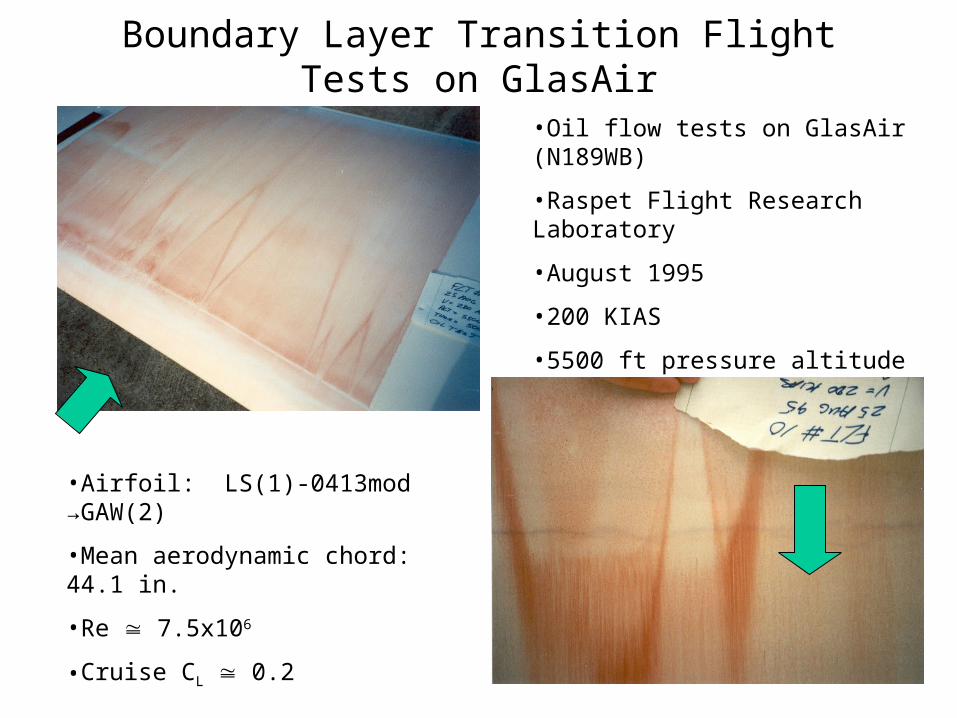
Boundary Layer Transition Flight Tests on GlasAir
•Oil flow tests on GlasAir (N189WB)
•Raspet Flight Research Laboratory
•August 1995
•200 KIAS
•5500 ft pressure altitude
•Airfoil: LS(1)-0413mod →GAW(2)
•Mean aerodynamic chord: 44.1 in.
•Re 7.5x10⁶
•Cruise CL 0.2

Drag Benefit of Laminar Flow
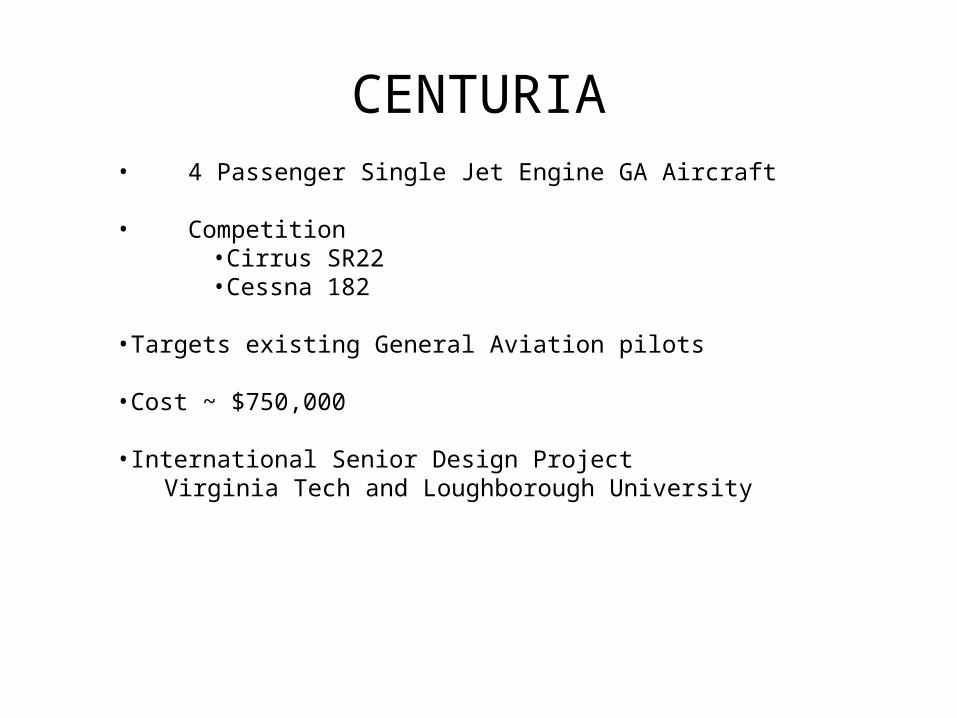
CENTURIA• 4 Passenger Single Jet Engine GA Aircraft
• Competition•Cirrus SR22•Cessna 182
•Targets existing General Aviation pilots
•Cost ~ $750,000
•International Senior Design ProjectVirginia Tech and Loughborough University
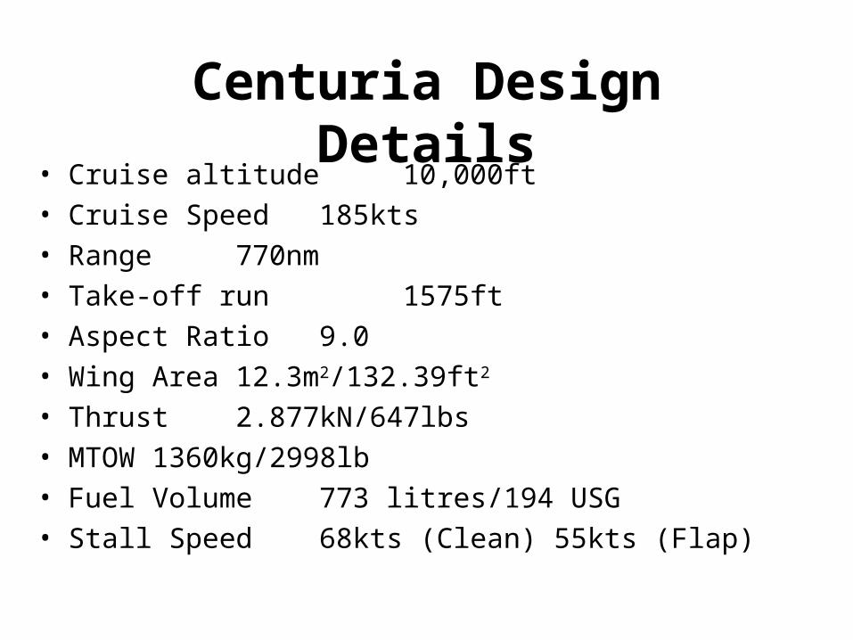
Centuria Design Details• Cruise altitude 10,000ft
• Cruise Speed 185kts
• Range 770nm
• Take-off run 1575ft
• Aspect Ratio 9.0
• Wing Area 12.3m2/132.39ft2
• Thrust 2.877kN/647lbs
• MTOW 1360kg/2998lb
• Fuel Volume 773 litres/194 USG
• Stall Speed 68kts (Clean) 55kts (Flap)

Drawing by Anne Ocheltree & Nick Smalley

Calculating Laminar Flow60% 100%Laminar
Turbulent
Laminar Turbulent
Wing & Tail
Fuselage
0005.0Re
328.1
0032.0)144.01(Re)(log
455.065.0258.2
10
==
=+
=
f
f
CLam
MCTurbulent
40% 100%

Fuselage Laminar to max thickness
Wing60% LM flow upper and lower surface
V-Tail60% LM flow upper and lower surface
Structure SWET (in2
) Turb C d Lam Cd % Reduction
Wing 224.89 0.00875 0.00268 69.41Tail 58.39 0.00211 0.00070 67.05
Fuselage 295.87 0.00975 0.00473 51.51
SREF (in2
) 132.72
Mcruise 0.29Recruise 5.88E+06

Reduction in Drag from Laminar flow
0
0.005
0.01
0.015
0.02
0.025
Turb Cd Lam Cd
Cd
Fuselage
Tail
Wing
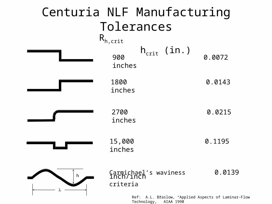
Centuria NLF Manufacturing Tolerances
Rh,crit hcrit (in.)
900 0.0072 inches
1800 0.0143 inches
2700 0.0215 inches
15,000 0.1195 inches
Carmichael’s waviness 0.0139 inch/inchcriteria
Ref: A.L. Braslow, “Applied Aspects of Laminar-Flow Technology,” AIAA 1990
h

Conclusions
• Natural Laminar Flow– Improvement of materials and computational methods
allows inverse airfoil design for desired characteristics or specific configurations
• Laminar Flow Control– LFC is a mature technology that has yet to become
commercially viable
• Drag Benefit on Centuria– 61% reduction in skin friction drag due use of laminar
flow on wings, tail and fuselage
References•Abbott, I.,H., Von Doenhoff, A.,E., Stivers, L.,S., “Summary of Airfoil Data,” NACA Report 824, 1945.•Loftin, L., K., “Theoretical and Experimental Data for a Number of NACA 6A-Series Airfoil Sections,” NACA Report 903, 1948.•Drela, M., “XFOIL 6.9 User Guide,” MIT Aero & Astro, 2001.•Green, Bradford, “An Approach to the Constrained Design of Natural Laminar Flow Airfoils,” NASA Contractor Report No. 201686, 1997.•Lutz, Th.,”Airfoil Design and Optimization”, Institute of Aerodynamics and Gas Dynamics, University of Stuttgart, 2000.•Garrison, P., “The Shape of Wings to Come,” Flying Magazine, November 1984.•McGhee,R.,J., Viken, J.,K., Pfenninger, W., Beasley, W.,D., Harvey, W.,D., “Experimental Results for a Flapped Natural-Laminar-Flow Airfoil with High Lift/Drag Ratio,” NASA TM 85788, 1984.•Fujino, M., Yoshizaki, Y., Kawamura, Y., “Natural-Laminar-Flow Airfoil Development for the Honda Jet,” AIAA 2003-2530, 2003.•McCormick, B.,W., Aerodynamics, Aeronautics and Flight Mechanics, 2nd Edition, John Wiley & Sons, New York, 1995.•“Applied Aerodynamic Drag Reduction Short Course,” University of Kansas Division of Continuing Education, Williamsburg, VA 1990. •Smith, A.,M.,O., “High-Lift Aerodynamics,” Journal of Aircraft, Volume 12, Number 6, June 1975.•Schetz, J.,A., Boundary Layer Analysis, Prentice Hall, Upper Saddle River, New Jersey, 1993.•Cornish, J.,J., “A Summary of the Present State of the Art in Low Speed Aerodynamics,” Mississippi State University Aerophysics Department Internal Memorandum, 1963.•Raymer, D.,P., Aircraft Design: A Conceptual Approach, AIAA Education Series, 1989.•Braslow, A.,L., Maddalon, D.,V., Bartlett, D.,W., Wagner, R.,D., Collier, F.,S., “Applied Aspects of Laminar-Flow Technology,” Appears in Viscous Drag Reduction in Boundary Layers, AIAA Progress in Astronautics and Aeronautics, Volume 123, 1990.


