1 Laser-based satellite communication systems stabilized by non- mechanical electro-optic scanners Michael Ziemkiewicz, Scott R. Davis, Scott D. Rommel, Derek Gann, Ben Luey, Joseph D. Gamble, and Mike Anderson Vescent Photonics Inc., 14998 W. 6 th Ave. Suite 700, Golden CO 80401 ABSTRACT Laser communications systems provide numerous advantages for establishing satellite-to-ground data links. As a carrier for information, lasers are characterized by high bandwidth and directionality, allowing for fast and secure transfer of data. These systems are also highly resistant to RF influences since they operate in the infrared portion of the electromagnetic spectrum, far from radio bands. In this paper we will discuss an entirely non-mechanical electro-optic (EO) laser beam steering technology, with no moving parts, which we have used to form robust 400 Mbps optical data connections through air. This technology will enable low cost, compact, and rugged free space optical (FSO) communication modules for small satellite applications. The EO beam-steerer at the heart of this system is used to maintain beam pointing as the satellite orbits. It is characterized by extremely low values for size, weight and power consumption (SWaP) – approximately 300 cm 3 , 300 g, and 5 W respectively, which represents a marked improvement compared to heavy, and power-consuming gimbal mechanisms. It is capable of steering a 500 mW, 1 mm short wave infrared (SWIR) beam over a field of view (FOV) of up to 50º x 15º, a range which can be increased by adding polarization gratings, which provide a coarse adjust stage at the EO beam scanner output. We have integrated this device into a communication system and demonstrated the capability to lock on and transmit a high quality data stream by modulation of SWIR power. Keywords: free space optical communications, laser comm., electro-optic laser scanner, non-mechanical scanner, laser scanner, cube-sat, micro-sat, beam steering, satcom. 1. INTRODUCTION & OVERVIEW In this paper we will discuss the design and feasibility of extremely low Size, Weight, and Power (SWaP) non- mechanical, electro-optic (EO) laser beamsteerers that are optimized for space based laser communications (lasercom). The target performance is summarized in Table 1. These new beamsteerers, which will finally satisfy the decades long dream of providing a viable alternative to opto-mechanics, will controllably steer high power ( > 10 Watts), low divergence ( < 100 microradians) lasers with no moving parts. Novel self-calibrating, closed-loop stabilization techniques will provide very high pointing stability ( < 10 microradians). This device is currently being developed as part of NASA phase II and III SBIR programs. The outcome will provide a critical component to help lasercom fulfill its long-standing scientific and commercial promise. The need for increased space-based connectivity is pressing; the world’s continued thirst for “more information faster” coupled with emergent data-intensive collection concepts and dramatic reductions in satellite payload sizes (e.g., cubesats) will necessitate new communications capabilities to avoid bottlenecks. Unfortunately, conventional RF links can be SWaP consumptive and often provide limited bandwidth (< Gbps, often much less), thereby hampering scientific discovery and commercial utility. Lasercom has long been discussed as a solution. 1 The inherent lower beam divergence at laser vs. radio frequencies can direct more power onto the receive aperture which can result in dramatically higher link bandwidths. Of course, this lower divergence necessitates accurate laser pointing and control which is often challenging.
Transcript
1
Laser-based satellite communication systems stabilized by non-mechanical electro-optic scanners
Michael Ziemkiewicz, Scott R. Davis, Scott D. Rommel, Derek Gann, Ben Luey, Joseph D. Gamble,
and Mike Anderson Vescent Photonics Inc., 14998 W. 6th Ave. Suite 700, Golden CO 80401
ABSTRACT
Laser communications systems provide numerous advantages for establishing satellite-to-ground data links. As a carrier for information, lasers are characterized by high bandwidth and directionality, allowing for fast and secure transfer of data. These systems are also highly resistant to RF influences since they operate in the infrared portion of the electromagnetic spectrum, far from radio bands. In this paper we will discuss an entirely non-mechanical electro-optic (EO) laser beam steering technology, with no moving parts, which we have used to form robust 400 Mbps optical data connections through air. This technology will enable low cost, compact, and rugged free space optical (FSO) communication modules for small satellite applications. The EO beam-steerer at the heart of this system is used to maintain beam pointing as the satellite orbits. It is characterized by extremely low values for size, weight and power consumption (SWaP) – approximately 300 cm3, 300 g, and 5 W respectively, which represents a marked improvement compared to heavy, and power-consuming gimbal mechanisms. It is capable of steering a 500 mW, 1 mm short wave infrared (SWIR) beam over a field of view (FOV) of up to 50º x 15º, a range which can be increased by adding polarization gratings, which provide a coarse adjust stage at the EO beam scanner output. We have integrated this device into a communication system and demonstrated the capability to lock on and transmit a high quality data stream by modulation of SWIR power.
In this paper we will discuss the design and feasibility of extremely low Size, Weight, and Power (SWaP) non-mechanical, electro-optic (EO) laser beamsteerers that are optimized for space based laser communications (lasercom). The target performance is summarized in Table 1. These new beamsteerers, which will finally satisfy the decades long dream of providing a viable alternative to opto-mechanics, will controllably steer high power ( > 10 Watts), low divergence ( < 100 microradians) lasers with no moving parts. Novel self-calibrating, closed-loop stabilization techniques will provide very high pointing stability ( < 10 microradians). This device is currently being developed as part of NASA phase II and III SBIR programs. The outcome will provide a critical component to help lasercom fulfill its long-standing scientific and commercial promise.
The need for increased space-based connectivity is pressing; the world’s continued thirst for “more information faster” coupled with emergent data-intensive collection concepts and dramatic reductions in satellite payload sizes (e.g., cubesats) will necessitate new communications capabilities to avoid bottlenecks. Unfortunately, conventional RF links can be SWaP consumptive and often provide limited bandwidth (< Gbps, often much less), thereby hampering scientific discovery and commercial utility. Lasercom has long been discussed as a solution.1 The inherent lower beam divergence at laser vs. radio frequencies can direct more power onto the receive aperture which can result in dramatically higher link bandwidths. Of course, this lower divergence necessitates accurate laser pointing and control which is often challenging.
2
At Vescent we have developed a new, proprietary approach to non-mechanically steer laser beams over a wide field of view (FOV). In this paper we will present data that indicates these beamsteerers can be modified to meet the stringent requirements of space based lasercom. As part of ongoing development programs at Vescent we will build, test, and provide disruptive EO scanner systems optimized for lasercom needs. In addition to enabling scientific goals, discussions with commercialization partners point to a strong market potential for these EO beamsteerers.
Table 1: Target performance of the low-divergence EO beamsteerers currently being developed for lasercom applications.
Operational Wavelength 1.5 microns This development is for SWIR. NIR scanners can be made from different
materials. Beam Divergence < 100 microradians Diffraction limit for 1 cm beam
Max. Optical Power (pulsed) > 4 kW Tested for 5 nsec pulse for limited exposure time.
Max. Optical Output Power CW > 10 W Maximum not known.
Electrical Power Consumption < 50 milliWatts Equivalent to driving a 5 nF
capacitor, power required depends on scan frequency.
Scanner Chip Dimensions 5 × 4 × 0.3 cm Fiber Packaged Dimensions To be smaller than 7 x 5 x 5 cm
Operational Temperature Range 0 oC < TOP < 60 oC Can be extended if needed Storage Temperature Range -40 oC < TST < 100 oC Can be extended if needed
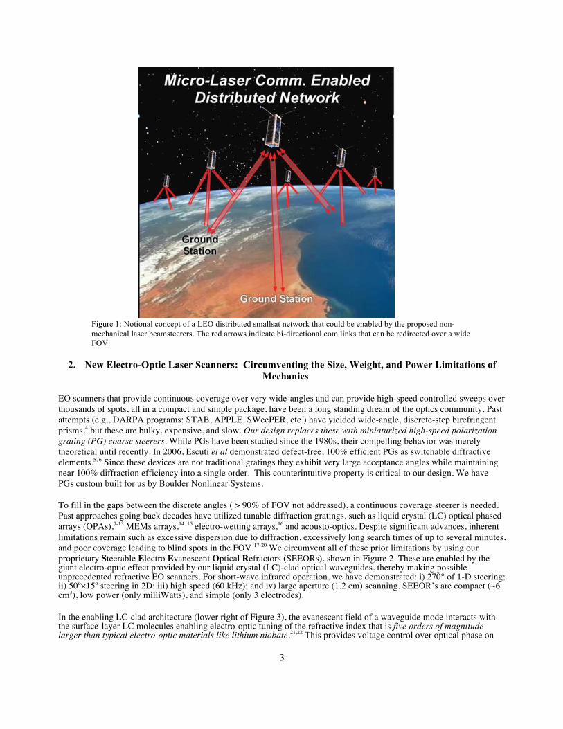
The advantages of lasercom over conventional radio frequency (RF) communications have long been appreciated, e.g. security, high-bandwidth, lack of radio frequency interference (RFI), and lack of frequency allocation requirements.1 These factors have motivated recent, near-term and long-term NASA plans including: i) the Tracking and Data Relay Satellite System (TDRSS), which is part of the Space Communications and Navigation (SCaN) Program;2 ii) the OPALS mission (Optical PAyload for Lasercom Science), which will be a demonstration mission for optical communications from the International Space Station; iii) the optical comm. trunkline on the Mars 2022/2024 orbiter as a followup to a Deep Space Optical Communications 2020 demo; iv) deep space cube-sat optical links; and v) a planetary lander/rover optical proximity link demo on a future Mars sample return mission. The potential payoff to NASA is significant, and the commercial impact is also substantial. Compact lasercom modules enabled by these EO beamsteerers will enable high bandwidth communications between miniature satellites (e.g. cube-sats), high altitude balloons,3 ground stations, satellite clusters, and/or airborne assets (see Figure 1), such as the ones being developed by BridgeSat, LEO-SAT, VIALIGHT Communications, Facebook, Google, and others. The beginning of the era of space based lasercom is upon us. Furthermore, this development is in alignment with NASA technology roadmaps and addresses NASA technology grand challenges by drastically increasing space communication link capacity at low earth orbit (LEO) and geosynchronous earth orbit (GEO).
3
Figure 1: Notional concept of a LEO distributed smallsat network that could be enabled by the proposed non-mechanical laser beamsteerers. The red arrows indicate bi-directional com links that can be redirected over a wide FOV.
2. New Electro-Optic Laser Scanners: Circumventing the Size, Weight, and Power Limitations of Mechanics
EO scanners that provide continuous coverage over very wide-angles and can provide high-speed controlled sweeps over thousands of spots, all in a compact and simple package, have been a long standing dream of the optics community. Past attempts (e.g., DARPA programs: STAB, APPLE, SWeePER, etc.) have yielded wide-angle, discrete-step birefringent prisms,4 but these are bulky, expensive, and slow. Our design replaces these with miniaturized high-speed polarization grating (PG) coarse steerers. While PGs have been studied since the 1980s, their compelling behavior was merely theoretical until recently. In 2006, Escuti et al demonstrated defect-free, 100% efficient PGs as switchable diffractive elements.5, 6 Since these devices are not traditional gratings they exhibit very large acceptance angles while maintaining near 100% diffraction efficiency into a single order. This counterintuitive property is critical to our design. We have PGs custom built for us by Boulder Nonlinear Systems.
To fill in the gaps between the discrete angles ( > 90% of FOV not addressed), a continuous coverage steerer is needed. Past approaches going back decades have utilized tunable diffraction gratings, such as liquid crystal (LC) optical phased arrays (OPAs),7-13 MEMs arrays,14, 15 electro-wetting arrays,16 and acousto-optics. Despite significant advances, inherent limitations remain such as excessive dispersion due to diffraction, excessively long search times of up to several minutes, and poor coverage leading to blind spots in the FOV.17-20 We circumvent all of these prior limitations by using our proprietary Steerable Electro Evanescent Optical Refractors (SEEORs), shown in Figure 2. These are enabled by the giant electro-optic effect provided by our liquid crystal (LC)-clad optical waveguides, thereby making possible unprecedented refractive EO scanners. For short-wave infrared operation, we have demonstrated: i) 270° of 1-D steering; ii) 50o×15o steering in 2D; iii) high speed (60 kHz); and iv) large aperture (1.2 cm) scanning. SEEOR’s are compact (~6 cm3), low power (only milliWatts), and simple (only 3 electrodes).
In the enabling LC-clad architecture (lower right of Figure 3), the evanescent field of a waveguide mode interacts with the surface-layer LC molecules enabling electro-optic tuning of the refractive index that is five orders of magnitude larger than typical electro-optic materials like lithium niobate.21,22 This provides voltage control over optical phase on
4
the order of millimeters! Horizontal beam steering is achieved by prism-shaped electrodes whose index may be voltage tuned by 0.04 out of n = 1.75 (lower left of Figure 3). Vertical beam steering is achieved by allowing the evanescent field to tunnel into the high-index substrate (high index glass for λ < 1.2 µm) by tapering the subcladding. An S-taper provides a Gaussian output with M2 ~ 1. The output angle θvertical may then be voltage tuned.
Figure 2: TOP LEFT) Pictures of recent continuous converge SEEOR devices built at Vescent. TOP RIGHT) Possible 120o×120o EO laser scanner, containing a stack of several polarization gratings (PG’s). The quarter is included for scale. BOTTOM) System design with co-packaged SEEOR and PG stack.
Figure 3: New wide angle, continuous, refractive EO scanners as recently demonstrated by Vescent Photonics. The light is steered via a voltage tunable Snell’s law refraction, either with prism electrodes (horizontal) or an out-coupling prism (vertical). The light input and output is a collimated beam.
We have built SEEOR chips that provide 50o × 15o of continuous EO scan angle for lasers operating at telecom wavelengths (see Figure 4).
5
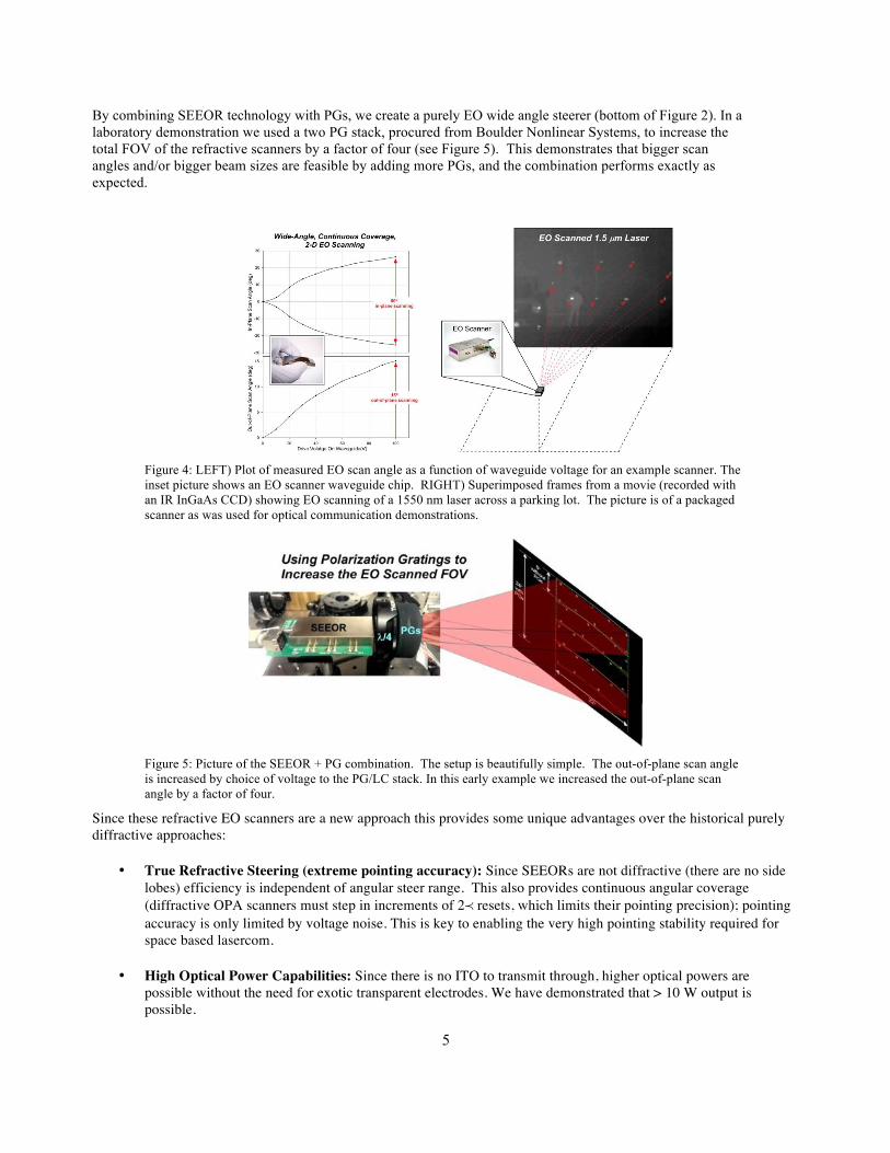
By combining SEEOR technology with PGs, we create a purely EO wide angle steerer (bottom of Figure 2). In a laboratory demonstration we used a two PG stack, procured from Boulder Nonlinear Systems, to increase the total FOV of the refractive scanners by a factor of four (see Figure 5). This demonstrates that bigger scan angles and/or bigger beam sizes are feasible by adding more PGs, and the combination performs exactly as expected.
Figure 4: LEFT) Plot of measured EO scan angle as a function of waveguide voltage for an example scanner. The inset picture shows an EO scanner waveguide chip. RIGHT) Superimposed frames from a movie (recorded with an IR InGaAs CCD) showing EO scanning of a 1550 nm laser across a parking lot. The picture is of a packaged scanner as was used for optical communication demonstrations.
Figure 5: Picture of the SEEOR + PG combination. The setup is beautifully simple. The out-of-plane scan angle is increased by choice of voltage to the PG/LC stack. In this early example we increased the out-of-plane scan angle by a factor of four.
Since these refractive EO scanners are a new approach this provides some unique advantages over the historical purely diffractive approaches:
• True Refractive Steering (extreme pointing accuracy): Since SEEORs are not diffractive (there are no side lobes) efficiency is independent of angular steer range. This also provides continuous angular coverage (diffractive OPA scanners must step in increments of 2≺ resets, which limits their pointing precision); pointing accuracy is only limited by voltage noise. This is key to enabling the very high pointing stability required for space based lasercom.
• High Optical Power Capabilities: Since there is no ITO to transmit through, higher optical powers are possible without the need for exotic transparent electrodes. We have demonstrated that > 10 W output is possible.
6
• Rapid Scanning: The electro-evanescent architecture provides scanning rates across the full FOV from 2 kHz (current scanners) to 10’s of kHz (demonstrated a 60 kHz scanner).
• Very Low SWaP: The simplicity of the approach minimizes SWaP. Our scanners use only milliwatts of electrical power, weigh less than 10 grams, and take up less than 10 cm3 of volume.
• High Data Rate: The SEEOR single mode optical waveguide geometry is similar to telecom components that have demonstrated > 10 Gbit bandwidths. These also naturally mate to single mode fibers which is especially convenient for FSO applications.
• High Resolution: The ultimate metric for an EO scanner is the number of far-field resolvable spots (Nspots = beam divergence / FOV), or the related Lagrange number. The SEEOR+PG architecture enables wide aperture (up to a cm) and wide angle scanners with tens of thousands of 2-D resolvable spots in a remarkably simple device.
• Low Cost: The inherent simplicity of the SEEOR+PG device will enable dramatic cost savings in volume. Ultimately, the devices should be cost comparative to a calculator or watch display
The purpose of ongoing development programs at Vescent is to design, build and deliver EO beamsteerers that meet the stringent requirements of space based lasercom. Unique advantages to a non-mechanical lasercom approach include:
• Zero physical disturbance from the pointing system enables higher system pointing stability due to the absence of inertial effects and can enable simultaneous data collections and communications.
• Multiple downlink points from LEO possible: KHz bandwidth over continuous coverage wide angles provides the ability to rapidly target alternate ground receivers as an effective mitigation of the most significant FSO objection, weather-induced blockage. By enabling the system to “instantly” switch between many ground receivers that are hundreds or thousands of km separated, the system will nearly always have access for data downlink.
• Jitter compensation possible: This feature can be provided by the high accuracy, kHz laser beamsteerer. By closing the loop around onboard accelerometers, the system will be capable of stabilizing the downlink beam in the presence of other on-board mechanical disturbances.
These high fidelity beamsteerers can be modified to meet space based lasercom needs that include: i) sufficiently large beams (up to 1 cm diameter with a diffraction limited half angle beam divergence of < 100 µrad), ii) high coupling efficiency, iii) high optical powers (up to 10 Watts output for a 1 cm diameter beam), and iv) a technique to have very high pointing stability (less than 1/10th the beam divergence or ~ 10 µrad). These requirements inform the specifications shown in Table 1 and necessitate either a decrease in instrument FOV or the addition of a larger stack of PG’s.
Development of a working lasercom device: As part of our first development phase we completed a design and production run of EO scanners which were delivered to NASA Glenn and JPL for evaluation. Pictures of these devices are shown in Figure 6.
7
Figure 6: TOP LEFT) Picture of a fully packaged EO scanner device. This includes a FOV correction optic, fiber coupler, and all internal electronics. TOP RIGHT) A picture of the LC-waveguide EO scanner chip that is inside the package. BOTTOM) Picture of a mounted device showing the EO scannable FOV.
As a demonstration of the capabilities of this steering device for practical communication, we built a circuit for automatically finding and locking onto a desired receiver target using a 1 mm SWIR laser beam. Specifically, we created an error signal using a quad cell and combined that with servo electronics to provide feedback to the EO beam angle. The fast response time and high fidelity of the SEEOR beamsteerer thus enables a clear alternative to simply requesting a voltage based on a look up table. The setup (Figure 7) has a closed-loop bandwidth of greater than 20 kHz, more than enough to cancel out spacecraft vibrations. In the figure on the left, the beamsteerer (right side) is vibrated and the scanned SWIR beam is smeared or vibrated away from the target. In the figure on the right, two servo loops are engaged to cancel out the vibration and the spot is kept on target even in the presence of extreme vibrations. A movie of this feature may be seen here: https://www.youtube.com/watch?t=9&v=3JlHdqAneJU
Figure 7: Demonstration of servo or target locking the EO beamsteerer to compensate for a vibrating source.
This ability to feedback an error signal to the scanner is enabling. By actively measuring the difference between the desired and actual pointing angle, the error signal can be rapidly driven to zero. This maintains the desired pointing angle in a self-calibrating fashion.
8
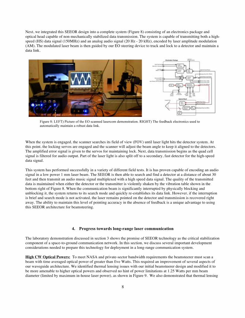
Next, we integrated this SEEOR design into a complete system (Figure 8) consisting of an electronics package and optical head capable of non-mechanically stabilized data transmission. The system is capable of transmitting both a high-speed (HS) data signal (150MHz) and an analog audio signal (20 Hz - 20 kHz), encoded by laser amplitude modulation (AM). The modulated laser beam is then guided by our EO steering device to track and lock to a detector and maintain a data link.
Figure 8: LEFT) Picture of the EO scanned lasercom demonstration. RIGHT) The feedback electronics used to automatically maintain a robust data link.
When the system is engaged, the scanner searches its field of view (FOV) until laser light hits the detector system. At this point, the locking servos are engaged and the scanner will adjust the beam angle to keep it aligned to the detectors. The amplified error signal is given to the servos for maintaining lock. Next, data transmission begins as the quad cell signal is filtered for audio output. Part of the laser light is also split off to a secondary, fast detector for the high-speed data signal.
This system has performed successfully in a variety of different field tests. It is has proven capable of encoding an audio signal in a low power 1 mm laser beam. The SEEOR is then able to search and find a detector at a distance of about 30 feet and then transmit an audio music signal multiplexed with a high speed data signal. The quality of the transmitted data is maintained when either the detector or the transmitter is violently shaken by the vibration table shown in the bottom right of Figure 8. When the communication beam is significantly interrupted by physically blocking and unblocking it, the system returns to its search mode and quickly re-establishes its data link. However, if the interruption is brief and search mode is not activated, the laser remains pointed on the detector and transmission is recovered right away. The ability to maintain this level of pointing accuracy in the absence of feedback is a unique advantage to using this SEEOR architecture for beamsteering.
4. Progress towards long-range laser communication
The laboratory demonstration discussed in section 3 shows the promise of SEEOR technology as the critical stabilization component of a space-to-ground communication network. In this section, we discuss several important development considerations needed to prepare this technology for deployment in a long-range communication system.
High CW Optical Powers: To meet NASA and private-sector bandwidth requirements the beamsteerer must scan a beam with time averaged optical power of greater than five Watts. This required an improvement of several aspects of our waveguide architecture. We identified thermal lensing issues with our initial beamsteerer design and modified it to be more amenable to higher optical powers and observed no hint of power limitations at 1.25 Watts per mm beam diameter (limited by maximum in-house laser power), as shown in Figure 9. We also demonstrated that thermal lensing
9
scales with beam size, as expected. This means that for a 1 cm diameter beam the optical power output limit is expected to be greater than 12 Watts.
Figure 9: Plot of the output beam from an LC waveguide constructed for higher power operation. The left plot shows 0.1 Watt coming out of the waveguide. The right plot shows 1.2 W coming out of the waveguide (limited by our maximum laser power). The beams are identical; no thermal lensing effects are observed. This is for a 1 mm diameter beam, so a 1 cm diameter beam will be able to pass more than 12 W of power.
Larger Apertures: In addition to enhancing power-handling characteristics, increasing the diameter of the steered laser beam from ~ 1 mm to ~ 1 cm will lead to a significant decrease in output beam divergence. This in turn means more power on the receiver target and longer-range lasercom capability. To accommodate these larger beams, we have designed and built improved couplers that maintain excellent fiber-to-waveguide coupling efficiency in this regime. With these new techniques, when increasing the beam size from 0.1 to 0.5 cm we observed no decrease in coupling efficiency (consistently >70%). Furthermore, we modified our theoretical models to design couplers with a theoretical 100% efficiency. Figure 10 shows the concept for anamorphically expanding the beam prior to coupling into the waveguide, the right side of the figure shows the built hardware. In this image the beam expander is mounted onto a fixture that also holds the waveguide. The coupled and scannable beam is visible on the IR view card at the top of the photograph in the image on the right.
Figure 10: LEFT) Pictures of the design for the anamorphic prism pair holder that spreads out the beam diameter in the in-plane dimension. We have a set of blocks to create beam diameters from 2 mm up to 5 mm. RIGHT) Picture of the built beam expander as it is mounted to a waveguide. In this image the wider beam is coupled into the waveguide and can be seen exiting the waveguide and striking an IR view card.
Final Lasercom Beamsteerer Design: We designed an EO scanner chip for steering a 1 cm wide beam that meets the performance requirements listed in Table 1. This design includes a concept for actively measuring the scan angle while in operation. A schematic of a lasercom optimized EO scanner system is shown in Figure 11. The output from a single
10
mode PM fiber will be collimated via a small aspherical lens into a 1 mm round beam. This round beam will be elongated into a 10 x 1 mm wide beam by a set of anamorphic prisms. This elongated beam will couple into the LC waveguide via a polished facet, as we demonstrated above. A larger aperture horn electrode will steer this 1 cm wide guided beam horizontally. A stretched outcoupling taper will stretch the output beam, to yield a 1 cm round output. It will be steered vertically via the tunable output coupler. For the index modulations we routinely realize, this will result in 6o of vertical steering, which can be increased to 18o via a double PG stack.
Figure 11: Schematic of a lasercom-optimized EO scanner design. A SEEOR chip will continuously steer a 1 cm beam over an 18o×6o FOV. A double PG stack will increase the FOV to 18o×18o. A high speed InGaAs array will actively measure the scan angle to self-calibrate the device.
The output beam will leave the silicon substrate via the polished facet. The angle is chosen to be close to Brewster’s angle, but it is not exactly at Brewster’s angle. A small reflection at the facet provides a “ghost” reflection that is internally reflected nearly vertical to the SEEOR chip. An InGaAs PIN array images this beam. This is shown in Figure 12, along with an example imaged “ghost” beam. This beam is extremely Gaussian and straightforward algorithms can find the center extremely precisely. For a 512 element array, the S/N of the image will allow the centroid to be found to 1/10th of a pixel, which is one part in 5000. By designing the imaging optics appropriately this will provide the desired angle accuracy. Furthermore, by steering to a known angle (rather than a known voltage) this will compensate for aging effects. The feedback scheme will be analogous to what has already been demonstrated in Figure 7.
11
Figure 12: Side view of the lasercom beamsteerer output section. The out-coupling silicon facet is set to be very close to Brewster’s angle. A “ghost” beam from the small Fresnel reflection will be measured by an InGaAs array. This provides an active measure of the scan angle which can be fed back to the control voltages.
5. CONCLUSIONS We have demonstrated the feasibility of adapting novel electro-evanescent refractive beamsteerers to meet lasercom needs. To this end, we have developed a full system capable of encoding audio and high speed data together on a modulated 1 mm SWIR laser beam which is actively steered to maintain a free space datalink to a rapidly-moving detector. We have also presented the results of a design and testing effort for preparing this technology for use over the long distances needed for satellite communication. This included: i) developing a coupling technique to increase the beam size without a penalty on coupling efficiency, ii) demonstrating optical power handling capabilities that will provide > 10 W of time averaged output power, and iii) unique schemes to close the loop on the pointing angle to provide “self-calibrated” high pointing accuracy. We also improved the performance and manufacturing process of the scanner technology. In ongoing efforts we will design, build, and deliver EO scanners optimized to meet the requirements of NASA lasercom missions such as the Optical comm. trunkline on Mars 2022/2024 orbiter as a follow on to a Deep Space Optical Communications 2020 demo, deep space cubesats optical links, and a planetary lander/rover optical proximity link demo on future Mars sample return mission.
6. ACKNOWLEDGMENTS This authors wish to thank William Farr, Dan Raible, and Afroz Zamon for useful discussions. This research was funded by NASA phase I SBIR NNX15CP63P and NASA phase III SBIR NNX15CC05P.
12
7. REFERENCES [1] Davis, C. C., Smolyaninov, I. I., and Milner, S. D., "Flexible optical wireless links and networks," IEEE
Communications Magazine 41, 51-57 (2003). [2] Coldewey, D., "Lasers, orbital Wi-Fi, and more in the works for NASA's space Internet," in Future Tech on
NBCNews.com (2013). [3] Rhodes, J., and et al., "Space-quality data from balloon-borne telescopes: the High Altitude Lensing Observatory
(HAL)," Astropartical Physics 38, 31-40 (2012). [4] McManamon, P., et al., "A Review of Phased Array Steering for Narrow-Band Electrooptical Systems,"
Proceedings of the IEEE 97, 1078 (2009). [5] Kim, J., Oh, C., Serati, S. A., and Escuti, M. J., "Wide-angle, nonmechanical beam steering with high throughput
utilizing polarization gratings," Applied Optics 50, 2636 (2011). [6] Nersisyan, S. R., Tabiryan, N. V., Steeves, D. M., and Kimball, B. R., "The principles of laser beam control with
polarization gratings introduced as diffractive waveplates," Proc. SPIE 7775, 77750U-77751 (2010). [7] Kahn, S. A. and Riza, N. A., "Demonstration of 3-dimensional wide angle laser beam scanner using liquid
crystals," Optics Express 12, 868-882 (2004). [8] Meyer, H., Riekmann, D., Schmidt, K. P., Schmidt, U. J., Rahlff, M., Schroder, E., and Thrust, W., "Design and
performance of a 20-stage digital light beam deflector," Applied Optics 11, 1732 (1972). [9] Schmidt, U., and Hust, W., "Optical deflection system including an alternating sequence of birefringent prisms
and polarizers," U.S. Patent 3,572,895 (1986). [10] Kim, J., Oh, C., Escuti, M. J., Hosting, L., and Serati, S. A., "Wide-angle, nonmechanical beam steering using
thin liquid crystal polarization gratings," in Advanced Wavefront Control: Methods, Devices, and Applications VI, (SPIE, 2008), pp. 709302-709301.
[11] Borel, J., Deutch, J.-C., Labrunie, G., and Robert, J., "Liquid Crystal Diffraction Grating," U. S. P. Office, ed. (Commissariat A L'Energie Atomique, 1974).
[12] Huignard, J. P., Malard, M., and Corlieu, G. d., "Static Deflector Device for An Infrared Beam," U. S. P. a. T. Office, ed. (Thomson-CSF, USA, 1987).
[13] McManamon, P., Bos, P. J., Escuti, M. J., Heikenfeld, J., Serati, S. A., Xie, H., and Watson, E. A., "A Review of Phased Array Steering for Narrow-Band Electrooptical Systems," Proceedings of the IEEE 97, 1078-1096 (2009).
[14] Ryf, R., Stuard, H. R., and Giles C. R., "MEMS tip/tilt & piston mirror arrays as diffractive optical elements," Proceeding of SPIE, Bellingham, WA 5894, 58940C-58941-58911 (2005).
[15] Krishnamoorthy, K., Li, K., Yu, D., Lee, D., Heritage, J. P., and Solgaard, O., "Dual mode micromirrors for optical phased array applications," Sensors and Actuators A A97-98, (2002).
[16] Smith, N. R., Abeysinghe, D. C., Haus, J. W., and Heikenfeld, J., "Agile wide-angle beam steering with electrowetting microprisms," Optics Express 14, 6557-6563 (2006).
[17] Stockley, J. E., Serati, S. A., Sharp, G. D., Wang, P., Walsh, K. F., and Johnson, K. M., "Broadband Beam Steering," in SPIE Proceedings, (1997).
[18] Chiu, Y., Burton, R. S., Stancil, D. D., and Schlesinger, T. E., "Design and Simulation of Waveguide Electrooptic Beam Deflectors," Journal of Lightwave Technology 13, 2049 (1995).
[19] Chiu, Y., Zou, J., Stancil. D. D., and Schlesinger, T. E., "Shape-Optimized electrooptic beam scanners: Analysis, design, and simulation," Journal of Lightwave Technology 17, 108 (1999).
[20] Kim, J.-h., Sun, L., Jang, C.-h., Choi, C.-C., and Chen, R. T., "Polymer-based thermo-optic waveguide beam deflector with novel dual folded-thin-strip heating electrodes," Optical Engineering 42, 620-624 (2003).
[21] Scrymgeour, D. A., Barad, Y., Gopalan, V., Gahagan, K. T., Jia, Q., Mitchell, T. E., and Robinson, J. M., "Large-angle electro-optic laser scanner on LiTaO3 fabricated by in situ monitoring of ferroelectric-domain micropatterning," Applied Optics 40, 6236 (2001).
[22] Nakamura, K., Miyazu, J., Sasaki, Y., Imai, T., Sasaura, M., and Fujiura, K., "Space-charge-controlled electro-optic effect: Optical beam deflection by electro-optic effect and space-charge-controlled electrical conduction," Journal of Applied Physics 104, 013105-013101 (2008).