LASER CUTTING MACHINE: JUSTIFICATION OF INITIAL COSTS Dwarakish Nagaraja, BS Thesis Prepared for the Degree of MASTER OF SCIENCE UNIVERSITY OF NORTH TEXAS May 2001 APPROVED: Ratan Kumar, Major Professor and Coordinator of Mechanical Engineering Technology Mark Woodruff, Manufacturing Manager, Montgomery KONE Inc, Industrial Representative Philip Foster, Committee Member Roman Stemprok, Committee Member Albert B. Grubbs, Jr, Chair of the Department of Engineering Technology C. Neal Tate, Dean of the Robert B. Toulouse School of Graduate Studies
Transcript
LASER CUTTING MACHINE: JUSTIFICATION OF INITIAL COSTS
Dwarakish Nagaraja, BS
Thesis Prepared for the Degree of
MASTER OF SCIENCE
UNIVERSITY OF NORTH TEXAS
May 2001
APPROVED:
Ratan Kumar, Major Professor and Coordinator ofMechanical Engineering Technology
Mark Woodruff, Manufacturing Manager, MontgomeryKONE Inc, Industrial Representative
Philip Foster, Committee MemberRoman Stemprok, Committee MemberAlbert B. Grubbs, Jr, Chair of the Department of
Engineering TechnologyC. Neal Tate, Dean of the Robert B. Toulouse School of
Graduate Studies
Nagaraja, Dwarakish, Laser Cutting Machine: Justification of initial costs. Master
of Science (Engineering Technology), May 2001, 68 pp., 9 tables, 15 illustrations, 14
references.
The Industrial Laser is firmly established in metalcutting as the tool of choice for
many applications. The elevator division of Montgomery KONE Inc., in an effort to
move towards quality, ontime, complete deliveries and 100% customer satisfaction,
decided to invest in new equipment to improve manufacturing processes. A huge
investment is proposed for a laser-cutting machine. It is the responsibility of
Manufacturing Engineering to direct the management by justifying its benefits, which
includes payback time and financial gains. Factors such as common line cutting,
automated material handling system and cutting time were involved in justification of the
initial cost of a laser-cutting machine. Comparative statistics on appropriate factors
accurately determine and justify the initial cost of a laser-cutting machine.
ii
ACKNOWLEDGEMENT
I first wish to express my gratitude to my advisor and major professor Dr. Ratan
Kumar. His encouragement and guidance throughout this work was invaluable. Dr.
Kumar was available to me even during weekends and late in the evenings to answer my
questions.
I also would like to thank Dr. Philip R. Foster, Associate Professor in the
Department of Engineering Technology, UNT, who helped me understand the basics of
Non-traditional manufacturing techniques. I also thank Dr. Roman Stemprock, Assistant
Professor in the Department of Engineering Technology, UNT, who was supportive in all
aspects during this work.
I wish to express my sincere gratitude to Mr. Mark Woodruff, Manufacturing
Manager, KONE Inc., for providing me with the required resources for this study. I
strongly believe that, without Mr. Woodruff’s help, this work would not have been
completed.
I would also like to thank Mr. Jani Marjamaa, an intern at KONE Inc., for helping
me in creating spreadsheets for the data analysis.
Last but not the least, I would like to thank my wife for being a huge moral
support during this study.
iii
CONTENTS
Chapter Page
ACKNOWLEDGEMENTS ii
LIST OF TABLES v
LIST OF ILLUSTRATIONS vi
1. INTRODUCTION 1
Problem statement
Purpose
Issues addressed in the study
Statement of need
Research methodology
Assumptions
Limitations
Overview
2. REVIEW OF LITERATURE 16
Laser
Laser-cutting machine
Features
Relevance in KONE Inc.
3. DATA COLLECTION 31
Parts selection / Identification
Calculation of cutting times
Automated material handling
4. ANALYSIS AND RESULTS 44
Comparison / Correlation
Cost savings
Results
5. CONCLUSIONS 53
6. RECOMMENDATIONS 55
iv
7. APPENDIX 56
8. REFERENCES 67
v
LIST OF TABLES
Table Page
1.1 Comparison between plasma and laser 9
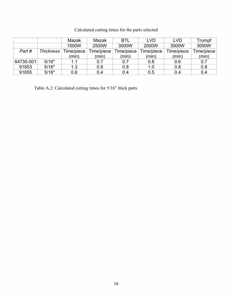
3.1 Calculated cutting times for some parts selected 42
3.2 Total cutting times per year 42
4.1 Sample cost comparison 45
4.2 Sample calculation in detail (Part number 53182-001) 46
4.3 Calculation of operating costs of laser-cutting machines 47
4.4 Sample cost savings on a LVD 3000W machine 50
4.5 Sample cost savings on a Mazak 2500W machine 50
4.6 Summary of savings 51
4.7 Comparison between actual cutting times and calculated cutting times 52
vi
LIST OF ILLUSTRATIONS
Illustration Page
1.1 Sample part manufactured using traditional equipment 5
1.2 Sample part identified for analysis 11
1.3 Sample part identified for analysis 12
2.1 Illustration of laser working 17
2.2 Illustration of 5” and 7.5” focal lengths 19
2.3 Types of laser beams 20
2.4 Illustration of commonline cutting and nesting 27
2.5 Laser-cutting machine with automated material handling 28
2.6 Sample of modular brackets included in the study 30
3.1 Sample of a new modular bracket 33
3.2 Sample of a new part design 34
3.3 Sample of a new part design 35
3.4 Decision matrix generated to identify the parts for this study 37-39
3.5 Sample calculation of cutting times using the software provided by Mazak 41
Corporation
4.1 Graph showing the comparison between actual cutting time and calculated 52
cutting time
1
CHAPTER 1
INTRODUCTION
This study is conducted in order to justify the initial costs of a laser-cutting
machine for KONE Inc. This work is a feasibility analysis based on various factors
relevant to KONE Inc.’s application.
Acquisition of new equipment in a manufacturing environment is a common
practice. Expensive equipment is procured to improve the efficiency of current
manufacturing processes and to save overall costs. Based on the application in a
particular type of industry, machinery is identified, selected, and procured. Justifying the
initial cost of the machine identified and selected is essential in order to project the cost
benefits and to calculate the payback time.
KONE Inc., one of the world leaders in elevators and escalators manufacturing, is
basically a fabrication industry. Most of the traditional manufacturing processes such as
shearing machines, press brakes and burn tables are used to make structural steel parts
required to build an elevator or an escalator. Elevators are designed to customer’s
specific requirements. These parts should also be designed for different seismic zones of
the world.
Manufacturing custom parts may be difficult with traditional equipment because it
calls for different kinds of die sets, punches and other tools to be stored in house. As a
result, KONE Inc. had been outsourcing most parts to various fabrication shops in the
area. However, company was paying premium prices to get these parts on time. The
2
management realized that the only solution was to invest in equipment that could
fabricate most of its structural parts.
The elevator division of KONE Inc., in an effort to move towards quality, ontime and
complete deliveries, and 100% customer satisfaction, decided to invest in new
manufacturing equipment. It became the responsibility of Manufacturing Engineering
personnel to identify the equipment needed and to justify the initial equipment
procurement costs. Initial research was conducted in order to identify the equipment,
which could benefit the company based on the application.
One sizable investment proposed was a laser-cutting machine. Manufacturing
engineering personnel had to justify the benefits, which included the payback time and
financial gains of the laser-cutting machine.
1.1 Problem Statement
The objective of this study is to justify the initial cost of the laser-cutting
machine for KONE Inc.’s application by including factors such as cutting time,
commonline cutting, automated material handling system, and power. A Laser-cutting
machine is expensive, with several features and options attached to the base machine.
Without generating statistics on these features and options, it is difficult to justify the
high initial cost. Previous studies conducted for various other applications by several
fabrication industries suggest the inclusion of all factors of the laser-cutting machine to
justify initial costs. Comparative study on these factors would help in accurately
justifying costs. This study would not only help KONE Inc. but also other elevator
manufacturers and similar fabrication industries.
3
1.2 Purpose
The purpose of this thesis is to generate comparative statistics on common line
cutting, cutting time, automated material handling and power of the laser-cutting machine
to accurately justify the machine’s initial costs. Laser-cutting machines come with
various options. The management of KONE Inc. looks for investment payback time and
cost savings after procuring the laser-cutting machine with various options.
The laser-cutting machine will reduce outsourcing, which will save the company
significant costs and will provide ontime control and complete products delivery.
Reduced outsourcing also helps in manufacturing schedule flexibility, which reduces
dependency. It also reduces the time lost in product transfer due to shipping
inconsistency. Reduction of outsourcing also helps the company in reducing split
shipments of the product, which is expensive.
Traditional equipment like shearing machines and punching machines are
inefficient in making complicated geometry. The procurement of the state-of -the -art
laser-cutting machine will significantly improve productivity and be cost effective.
1.3 Issues addressed in the study
The issues addressed in this study are:
1. Can the initial cost of a laser-cutting machine be justified for KONE Inc.’s
application?
2. Can a more powerful machine be justified for KONE Inc.’s application?
4
3. Can the extra investment for an automated material handling system as an
option to the base laser-cutting machine be justified for KONE Inc.’s
application?
4. Can faster cutting times help in justifying the initial costs of a laser-cutting
machine?
1.4 Statement of Need
There are various concerns regarding the current manufacturing processes being
employed at the facility (KONE Inc., McKinney, TX). These concerns lead to finding
solutions relevant to KONE Inc.’s requirements.
1. The shearing and punching machines currently used are inefficient. The
part shown in figure 1.1 is being manufactured using traditional shearing
and punching machines. The geometry of the part is difficult for the
traditional machines to handle. Tool changes make the process slow and
inefficient. Machines being used are old, depleted and have poor
repeatability and accuracy. There are no automated material handling
systems attached to the current machines. Therefore, operators are
involved in every operation, increasing the risk of operator injuries.
5
Figure 1.1: Sample part manufactured using traditional equipment
6
Absence of automated material handling systems also reduces the overall
efficiency of the manufacturing processes as a non-value added operation
such as material handling by operators is involved.
2. Product Design Flexibility is being compromised. The design engineers
have to be very conservative on tolerances and geometry. If tight
tolerances are absolutely required, the manufacturing of that particular part
is outsourced, which is costly. With the addition of laser-cutting machine
with automation, the efficiency of the process will improve and design
flexibility will be greatly enhanced, as there will be no custom tooling
involved. Skilled labor is required for specific part geometries, which
adds operating costs. Without automation, skilled labor is being wasted
for non-value-added material handling. Limiting skilled labor and
eliminating unskilled labor would eventually save operating costs.
1.5 Research Methodology
Areas included in this section are equipment selection criteria, part selection
techniques, identifying the major steps in conducting the study, data collection and the
analysis of collected data. The method of this research is descriptive.
There are several types of non-traditional equipment that could be useful for
KONE Inc.’s application. Some of them are laser-cutting machine, plasma cutting
machine, and abrasive waterjet machine.
7
Abrasive waterjet machining is extremely noisy. It has high consumable and
maintenance costs. It could also be messy due to the fact that abrasives and water used in
this process could rebound. Though abrasive waterjet machining has many advantages
such as low mechanical and thermal damage to the workpiece, minimal burr production
during the process, it was unacceptable to the management of KONE Inc. due to the fact
that it was messy and had high maintenance and consumable costs.
Thus, plasma cutting machine and laser-cutting machine were shortlisted for this
study.
To determine the best-suited machine for KONE Inc.’s application, the following
criteria were considered:
1. Process capability to ensure part accuracy. The manufacturing process should
be efficient enough to handle batch production with high repeatability to
manufacture parts with required tolerances. The process should be flexible for
manufacturing parts of various thicknesses without any significant loss of time
in tool changes. The parts manufactured should require minimum or no
secondary operations for finishing like deburring or grinding. The process
should have minimum setup times. The process should also have a safe and
clean work environment.
2. Fast and reliable unmanned operation. The process should be automated in
order to reduce labor. Non value added operations like material handling
(loading and unloading) should be minimum. The scrap handling or disposal
should be efficient. The process should be safe and reliable. Ease of use is an
issue as training and retraining costs should be low.
8
3. Operating costs should be less. The operating costs to run and maintain the
equipment should be relatively low. The initial costs of the equipment will
evidently affect the operating costs. There are various factors that could affect
the operating costs. Cutting speed, consumable costs and maintenance costs
are a few of the factors. In order to have low operating costs, cutting speed
should be high, consumable and maintenance costs should be low.
Companies of fine plasma and lasers addressed KONE Inc.’s current process and
application. Sample pieces of different material thickness were cut using both fine
plasma and laser. The observations were:
1. Lasers have one third the operating costs of fine plasma
2. Superior cut quality with the laser
3. Cutting time is shorter with fine plasma
4. Cutting speed drastically decreases for thicker materials with a laser
5. Fine plasma can cut thicker material (1/2” to 1”) faster and efficiently without
cutting edges being affected
6. Consumable costs with a laser is 1/6th the costs of fine plasma
7. Better aesthetics with a laser including cleanliness
The comparison is tabulated in table 1.1. Looking at the comparison, it was decided that a
laser-cutting machine is better suited for KONE’s application.
9
Plasma vs Laser
Selection Criteria Laser Fine plasma
Machine cost - +
Material Handling + 0
Consumable costs + -
Cutting speed - +
Operating costs + -
Material thickness 0 +
Service N/A N/A
Aesthetics + 0
(includes cleanliness)
Secondary operations + 0
(for cutting thicker material)
Total 2 1
Table 1.1: Comparison between plasma and laser
10
Parts that were planned to be cut by the laser-cutting machine were identified
based on the following factors: Annual usage, thickness of the material, geometry of the
part, and outsourced parts. Annual usage is the total quantity required for that particular
year. Thickness of the material selected for this study ranges from ¼ inch through ½inch.
Parts, which require more than one operation (like shearing and punching), with many
slots and holes, with offset holes and slots that could not be punched using unit tools and
parts that could not be manufactured in house were selected for this study. Some parts
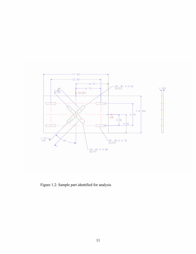
identified are shown in the figures 1.2 and 1.3.
The decision matrix used in the part selection process is presented in chapter 3.
Parts that satisfy at least two of the four factors are included in the study.
One hundred eighteen parts were identified from four thousand parts being
manufactured or purchased by KONE Inc.
Mazak Corporation, a leading laser-cutting machine manufacturer provided the
software to calculate the cutting time required to manufacture the selected one hundred
eighteen parts. Time taken to cut these parts was calculated using the software provided.
The cut time generated was used to calculate the cost of the part by adding the material
cost and the overhead costs. The cut time was compared with the present time to evaluate
the cost differentiation. The cost of the parts that were being outsourced was compared
with the new cost to evaluate the cost differentiation.
Depreciating cost for the laser-cutting machine was calculated using the least
squares method. Payback time for acquiring this machine was calculated with seven
years as the life of the machine (according to the machine manufacturer). Cost savings
were calculated based on cutting time comparison.
11
Figure 1.2: Sample part identified for analysis
12
Figure 1.3: Sample part identified for analysis
13
Conclusions were drawn from these results to provide future research directions.
Recommendations on acquiring a laser-cutting machine for the facility (KONE INC.) are
based on the pay back time calculated.
1.6 Assumptions
The assumptions applying to the research performed in this thesis are.
1. Operating costs to run a 3 kW laser-cutting machine is the same as a 2 kW
machine.
2. Brand names/Manufacturers of laser-cutting machines used in this
research will not impact the final results.
3. Cost of labor is the same throughout the time of this study.
4. Cost of electricity and gas remain constant throughout the time of this
study.
5. Operator and programmer training costs are the same as in traditional
manufacturing.
6. Software provided by Mazak Inc., for calculating cutting times is reliable.
7. The present cost of parts selected for this research is accurate.
8. The scrap recycling cost is negligible.
9. The machine efficiency is 80%.
14
1.7 Limitations
The limitations that apply to this thesis are
1. The study is limited to KONE part designs, which uses mostly A-36 grade
steel.
2. The study will be limited to the 118 parts identified. It is not feasible to
include all parts that will be eventually cut on the laser-cutting machine.
3. The study limits the thickness of the material that the laser –cutting
machine can handle to ½”. There are several parts ¾” thick which could
be cut on the laser-cutting machine. However, low annual usage of these
parts limits the inclusion of ¾” parts in this study.
4. Time involved in the justification process is not counted as an expense.
1.8 Overview
This thesis addresses the importance of accurately justifying the initial costs of a
laser-cutting machine utilizing commonline cutting, cutting time, automated material
handling system and machine power as factors. All these factors are discussed in terms
of advantages and disadvantages. This study has been conducted in accordance to KONE
Inc.’s applications, and part designs. The study also discusses the importance of
including all the factors and options of the laser-cutting machine in the analysis in order
to justify the high initial cost.
The purpose of research, problem statement, research questions and questions
related to the research method adopted, limitations, and assumptions are discussed in
15
chapter one. Chapter two describes the laser, laser-cutting machine, differences between
plasma arc cutting and laser cutting and advantages and disadvantages of each with
respect to KONE Inc.’s application. Machine power, commonline cutting, automation
and cutting times are also included. Chapter three discusses the methods of analysis data
collection and analysis. The actual data is also presented in this chapter. Comparison of
previous costs with future cost approximation is also included in this chapter. Payback
time and the cost savings are highlighted in this chapter. Chapter four provides the
results of the analysis. Conclusions and recommendations are discussed in chapter five
and six respectively.
16
CHAPTER 2
REVIEW OF LITERATURE
This chapter provides an overview of the laser and laser-cutting machine. The
principles of the laser beam generation and the technology involved in the laser cutting
machine is presented. Previous studies conducted on lasers and laser-cutting machines
were reviewed and suggestions and recommendations from those studies were used in the
current study.
2.1 LASER
The first LASER (Light Amplification by Stimulated Emission of Radiation) was
developed in early 1950’s. Principles of current lasers are the same as the first one
developed.
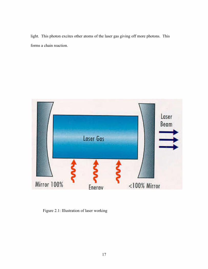
A laser beam is generated in a glass tube with a mirror at each end. The laser gas
is pumped into the glass and circulated by a turbine. One of the mirrors is 100 percent
reflective, and the other is less than 100 percent reflective (usually seventy percent) as
shown in figure 2.1. The laser gas can be a mixture of helium, carbon dioxide and
nitrogen. This mixture of laser gas is commonly known as a CO2 laser. There are several
other lasing gas mixtures available and in use but, for high powered industrial lasers, the
CO2 mixture is most common.
An external energy source such as electrical power (most commonly DC power)
or radio frequency (RF generator) excites the atoms in the laser gas mixture. When the
atoms of the laser gas becomes excited, the stimulated gas atoms give off a photon of
17
light. This photon excites other atoms of the laser gas giving off more photons. This
forms a chain reaction.
Figure 2.1: Illustration of laser working
18
The photons generated move back and forth between the two mirrors in the glass
tube until a portion escapes through the partially reflective (less than hundred percent
reflective) mirror.
Laser beam is monochromatic which means that it has the same frequency. The
light beam is coherent which means the frequency is in phase. The laser beam gets its
power when this monochromatic and coherent light is focussed.
The laser beam is focussed onto the workpiece to be cut. Matching the focal
length of the laser beam to the depth of the cut results in maximum productivity and the
best cut quality. The laser beam is “hourglass” shaped after passing through the machine
as shown in fig.2.2. The maximum power concentration in the beam is at its “waist” and
cuts best at that area. Focal length is measured from the lens to the center of the focus
waist. Common industrial focal lengths are 5 inches for thin and sheet metals and 7.5
inches for thicker material.
A 5-inch focal length beam has a shorter ‘waist” than the focal length of a 7.5-
inch focal length beam as shown in fig.2.2. In a shorter focal length beam, the angles that
form the top and bottom of the hourglass are more acute. This suits the thinner gage
material (16 gage – 1/8 inch). However, it may result in poor edge quality in thicker
plate material (1/4 inch and above). Due to this fact, it is very important to match focal
length to the material thickness.
Energy distribution is an important aspect in lasers. Mode quality in lasers is the
energy distribution of the beam through its entire power curve. Mode quality describes
how well the energy distribution remains reliable under different power levels.
19
Waist
Figure 2.2: Illustration of 5” and 7.5” focal lengths
20
To maintain to good edge quality, it is extremely critical to maintain a stable
discharge of the beam from the glass tube throughout the entire power range in high
power lasers.
Stable output design is most often used to create a working beam in lasers up to
2kW. In a stable output design, the beam diverges from the glass tube in a bell curve.
This is also known as Guassian mode and is shown in figure 2.3. Technically, its shape is
TEM 00, which stands for transverse electromagnetic 00. A laser using an unstable
design is called TEM 01 as shown in figure 2.3.
Figure 2.2: Types of laser beams
21
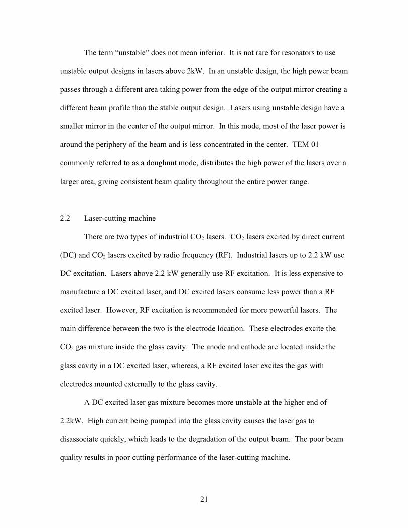
The term “unstable” does not mean inferior. It is not rare for resonators to use
unstable output designs in lasers above 2kW. In an unstable design, the high power beam
passes through a different area taking power from the edge of the output mirror creating a
different beam profile than the stable output design. Lasers using unstable design have a
smaller mirror in the center of the output mirror. In this mode, most of the laser power is
around the periphery of the beam and is less concentrated in the center. TEM 01
commonly referred to as a doughnut mode, distributes the high power of the lasers over a
larger area, giving consistent beam quality throughout the entire power range.
2.2 Laser-cutting machine
There are two types of industrial CO2 lasers. CO2 lasers excited by direct current
(DC) and CO2 lasers excited by radio frequency (RF). Industrial lasers up to 2.2 kW use
DC excitation. Lasers above 2.2 kW generally use RF excitation. It is less expensive to
manufacture a DC excited laser, and DC excited lasers consume less power than a RF
excited laser. However, RF excitation is recommended for more powerful lasers. The
main difference between the two is the electrode location. These electrodes excite the
CO2 gas mixture inside the glass cavity. The anode and cathode are located inside the
glass cavity in a DC excited laser, whereas, a RF excited laser excites the gas with
electrodes mounted externally to the glass cavity.
A DC excited laser gas mixture becomes more unstable at the higher end of
2.2kW. High current being pumped into the glass cavity causes the laser gas to
disassociate quickly, which leads to the degradation of the output beam. The poor beam
quality results in poor cutting performance of the laser-cutting machine.
22
As the RF excited laser will not pump high current into the gas mixture directly, it
allows the beam quality to be better even at high powers of up to 10kW. Better beam
quality is the main reason for RF excited lasers to be better performers in industries
which cut thicker material.
Use of solid circuitry to produce the RF excitation in place of vacuum tube
technology is the latest development in RF excited lasers. This solid state electronics
uses lesser (approximately 50 percent) power than the traditional RF laser. Reductions in
power requirements for a more powerful solid state RF laser has made the operating costs
almost the same as DC excited lasers. A powerful laser with low operating costs is the
main reason for fabrication shops to opt for a powerful laser, which is RF, excited. A
more powerful RF excited laser can handle various material thicknesses from sheet metal
to plate.
In addition to more powerful lasers, more production flexibility and higher cutting
rates, production shops are looking out for more work surface area to maximize the
number of parts per sheet of material. Optimum sheet utilization requires larger work
tables in laser-cutting machines. Normally, worktable sizes were 96-inch by 48-inch.
But, the manufacturing trend is forcing laser manufacturers to stretch worktable sizes.
Some machine manufacturers are making machines with 20 feet by 10 feet worktables.
These larger worktables not only help in making bigger parts but also help in better use of
nesting software which would reduce the scrap.
For this research, it is important to understand the differences between processing
with high power lasers and using 2kW or less. Applying the higher power gives the
23
manufacturing plant more flexibility and higher processing speeds. Bigger worktables
provide maximum sheet utilization, which translates into savings.
2.4 Features
A potential user will purchase a laser-cutting machine based on the
manufacturer’s specifications. Typically, after the installation the user expects the
machine to cut ¾ inch material the same way it cuts ¼ inch material. When users are
unable to get a consistent efficiency, frustration sets in. To avoid frustration, features,
options and the variables involved in cutting thicker material should be understood
properly. To achieve acceptable quality in a consistent part run, the machine should cut
parts with fine striations, without burn out, and with minimal dross. Part tolerances are
important with minimal heat affected zone (HAZ). To satisfy these issues, key
parameters such as optics, assist gas, material quality and other cutting parameters should
be strictly adhered.
1. Optics: The laser beam mode must remain stable, symmetrical, and
linearly consistent throughout the entire resonator power curve. If the
mode is not symmetric, the cut quality turns out poor. Beam delivery
optics and the focussing lens must be aligned well and clean. For larger
worktable machines, a collimator is required to ensure minimal beam
divergence. A collimator is an adaptive optic (a deformable mirror), in
addition to the internal optics of the machine and is typically found in
high-powered DC lasers and almost all RF lasers.
24
2. Assist Gas: There are two types of assist gases that could be used.
Oxygen and Nitrogen. Oxygen in the cut process has three basic
functions.
a. Provides energy for the exothermic reaction of iron with iron
oxide. The oxygen provides 40 percent of the energy in the cut
process and the laser beam provides the rest.
b. Provides mechanical energy to expel the molten material
generated while cutting.
c. Cools the cut zone and the work piece by means of forced
convection.
Using 99.998 percent pure oxygen increases the cutting speed and
improves edge quality. Oxygen flow into the cut zone is directly
proportional to the flow of molten material expelled from the cut zone.
Increasing nozzle diameter will reduce the gas pressure and will leave the
cutting lens susceptible to splatter. Less gas flow can increase the heat
build up during piercing and cutting.
3. Material quality: One of the main problems in laser cutting is adjusting
plate parameters for a material batch. Quality and consistency of material
vary from batch to batch. It is very hard to maintain the same parameters
and achieve consistent cuts in different batches of material. Material
property inconsistency is due to inconsistency in mill runs and
carbon/silicon composition in the material.
25
Material inconsistency is a great concern for programmers. Emphasis
must be placed on material consistency of especially with A-36 grade
steel. The surface must be rust free and mill scale. Rust can impede the
oxygen’s ability to assist in the cut process, causing cut out in certain
areas. Often a “laser grade” material is preferred over regular A-36 grade.
4. Cutting parameters: Cutting parameters contribute a significant value in
laser cutting. There are several cutting parameters involved in laser
cutting:
a. Piercing: Piercing is a process that starts the cut. Piercing will
allow the beam to blow through the material in seconds,
causing splatter, which may damage the cutting lens. The
programmer can control this parameter by allowing a cool
down period between pulses minimizing the heat effect. Pulse
piercing reduces heat effect. The size of the pierce should be
small to cool down the material between pulses. The best pulse
pierce frequencies are between 80-130 Hz with automatic pulse
increments of 20-30 percent. Pulse cutting helps reduce heat
build up during cutting. Pulse cutting could be best performed
at between 200-600 Hz. Pulse cutting is less susceptible to
resonant shock waves created by assist gas at higher feed rates.
b. Cutting speed: The NC program can achieve cutting speed
control. Different cutting speeds are used for different material
thicknesses. As material thickness increases, cutting speed
26
decreases. Decrease in cutting speeds maintains consistent cut
quality. Very slow cut rates might lead to heat build up and
create a heat-affected zone (HAZ) around the cut area.
c. Common line cutting: Parts should be nested and processed to
minimize the heat-affected zone (HAZ) and reduce tension on
the next part cut. Common line cutting cuts parts in alternate
group sequence with individual parts alternated. Alternating
depends on part contour. There is software available, which
optimally nests parts to reduce the HAZ. See figure 2.4. The
programmer should take extreme care in part selection when
nesting is being used with common line cutting. Web
thickness between nested part groups must be equal to or
greater than the material thickness in order to evenly dissipate
heat.
d. Focus types and position: Focussing systems automatically
lower and increase the focal position according to the
requirement preventing human error. Minimal heat will be
induced in the part utilizing lower pulse frequencies.
27
Figure 2.4: Illustration of commonline cutting and nesting
3. Automated material handling. This option, available with most base
machines, a load and unload cell attached to the laser-cutting machine
which does not require a separate controller. Automated material is an
option and could be integrated to the base machine and controlled by the
same controller. An automated material handling system would be
extremely beneficial for production shops handling heavier gage material.
The Automated material handling system makes the whole system safe
and efficient and totally unmanned. Figure 2.5 shows an example of an
automated material handling system that is integrated into the base laser-
cutting machine.
28
Figure 2.5: Laser-cutting machine with automated material handling
29
2.5 Relevance in KONE
A significant percentage of KONE parts are structural wall and rail brackets.
These bracket designs are shown in the figure 2.6. Most of the bracket designs
have slots and holes, sometimes with offsets. Traditionally, these brackets were
purchased by KONE from an external source due to the fact that, the
manufacturing plant did not have equipment to manufacture these parts in house.
With the requirement of these brackets running into thousands of pieces, it was
proving expensive to purchase these brackets from an external vendor. To solve
this problem, management plans to purchase equipment that has the flexibility,
speed and efficiency to manufacture brackets in house.
The review of literature indicates that a laser-cutting machine would be
suitable for a fabrication industry like KONE Inc. But as the equipment is
relatively expensive, justifying the initial cost of the machine was absolutely
required. This justification will help KONE management to invest in a laser-
cutting machine to make the process efficient and to save money over time.
Calculating payback time would make the justification transparent and easy for
management to make a decision to purchase this equipment. The analysis and
calculations of cost savings with different options are described in the next
chapter.
30
Figure 2.6: Sample of modular brackets included in the study
31
CHAPTER 3
DATA COLLECTION
To conduct this study, parts to be cut on the laser-cutting machine were identified
from several thousand parts manufactured by KONE Inc.
This chapter explains the data collection technique and provides the calculated
cutting times for selected parts. Software provided by Mazak Corporation was used to
calculate cutting times.
3.1 Parts selection / Identification
Parts to be analyzed were selected according to annual usage, complicated
geometry, parts that were being purchased and parts with thickness in the range of ¼ inch
through ½ inch. These parts were selected mostly by visual inspection. Suggestions
from several department experts were considered in the part selection process.
Fabrication experts in KONE Inc. suggested some parts that were difficult to manufacture
with traditional shearing and punching machines.
a. Annual usage: Annual usage was one of the main criteria for the
part selection process. Any part with an annual usage of less than
600 was not considered for this study. However, KONE Inc. had
several unit tools developed over a ten-year period that were being
used to manufacture parts with simple designs. Though the annual
usage of these parts was high, they were not considered for this
study, because experts in the fabrication department believed that it
would be easier to manufacture them with traditional equipment.
32
b. Complicated geometry: KONE Inc., in an effort to standardize the
product range, was moving towards standardized European part
designs. Some of the North American designs were being changed
to the European design. The European part design was more
complex in geometry, to reduce some of the custom designs for
elevators. The new designs had more flexibility and replaced
multiple parts. Research and Development engineers were
designing modular brackets with complicated geometry to provide
greater flexibility for construction engineers. The traditional
equipment available was not capable of making these parts. A
sample of the new modular bracket design is shown in figure 3.1.
c. Outsourced parts: Some of the new parts with complicated
geometry were being outsourced to fabrication shops due to the
lack of proper equipment or tools. Some part designs required
very tight tolerances, which was impossible to achieve with the
current equipment. A few of the new part designs are illustrated in
figures 3.1 and 3.2.
d. Thickness: Most of the parts that are manufactured for KONE Inc.
is between ¼ inch and ½ inch thick. There are parts that are more
than ½ inch, but not in great quantities.
33
Fig.3.1: Sample of a new modular bracket.
34
Fig.3.2: Sample of a new part design
35
Fig.3.3: Sample of a new part design.
36
Considering all these factors, a decision matrix was generated to identify the parts for this
study. The decision matrix is represented in figure3.4.
From the decision matrix, any part that satisfies at least two factors selected was
identified as a part for this study. 118 parts were identified for this study based on the
factors selected.
37
Part # Annual Usage >600
Purchased Complicatedgeometry
Thickness >= 1/4"
and <=1/2"17161434594563345634460354853348817502035020550342504315166751864520405204652051520605214652173523605246352464524935249552496
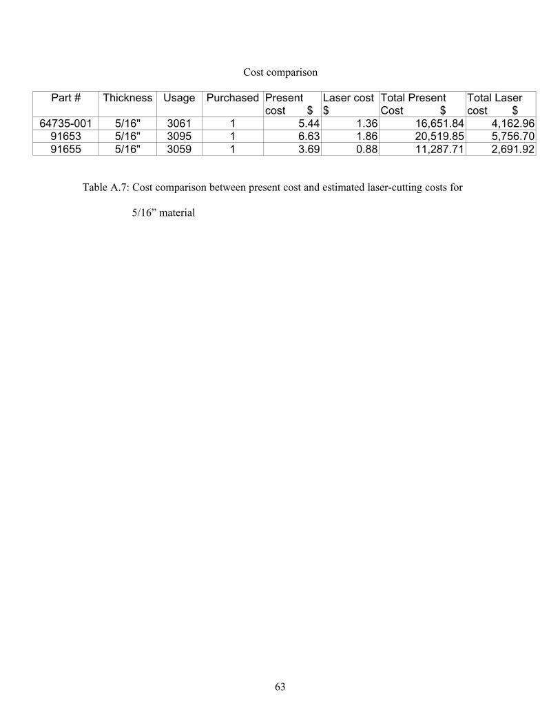
Cutting time 1.9 min Calculated using software provided by Mazak.Cost of cutting $ 1.83 =Part cutting time/60*(labor+lasercost)
Part dimensions 7.33 inches Dimensions of a smallest possible rectangle18 inches Which includes the whole part
Number of pieces / sheet 49 Size of the sheet is 5' x 10' and 90% of theSheet is being used.=(60"/dim 1 *120"/dim 2)*90%
Cost of raw material $ 160.48 Cost of a 5'x 10' sheetMaterial cost / piece $ 3.27 =Cost of a sheet / number of pieces in a sheet
Efficiency 80% With load and unload automationNumber of bends 1 Number of bends in the partCost of bending $ 0.05 =Number of bends*time of operation*labor
=Number*(10s/(3600s/hour))*($19.54/hour)Laser cost / part $ 5.61 =Laser cutting cost/Efficiency(%)
+material cost+cost of bendingPresent cost $ 8.75 Present cost