Abstract The continuing development of powerful laser systems has permitted toextend the interaction of laser beams with matter far into the relativistic domain,and to demonstrate new approaches for producing energetic particle beams. Theextremely large electric fields, with amplitudes exceeding the TV/m level, thatare produced in plasma medium are of relevance particle acceleration. Since thevalue of this longitudinal electric field, 10,000 times larger than those producedin conventional radio-frequency cavities, plasma accelerators appear to be verypromising for the development of compact accelerators. The incredible progressesin the understanding of laser plasma interaction physic, allows an excellent controlof electron injection and acceleration. Thanks to these recent achievements, laserplasma accelerators deliver today high quality beams of energetic radiation andparticles. These beams have a number of interesting properties such as shortness,brightness and spatial quality, and could lend themselves to applications in manyfields, including medicine, radio-biology, chemistry, physics and material science,security (material inspection), and of course in accelerator science.
11.1 Introduction
In 1979 Tajima and Dawson [1], on the basis of theoretical work and simula-tions, have shown that an intense electromagnetic pulse can create a weak ofplasma oscillation through the non linear ponderomotive force, demonstrating howrelativistic plasma can be suitable for the development of compact accelerators.
V. Malka (�)Laboratoire d’Optique Appliquée, ENSTA Paris Tech, CNRS,Ecole Polytechnique, UMR 7639, 91761 Palaiseau, Francee-mail: [email protected]
In the proposed schemes, relativistic electrons were injected externally and wereaccelerated through the very high electric field (GV/m) sustained by relativisticplasma waves driven by lasers. In this former article, the authors have proposedtwo schemes called the laser beat wave and the laser wakefield. Several experimentshave been performed in the beginning of the 1990s following their idea, andinjected electrons in the few MeV level have indeed been accelerated by electricfields in the GV/m range in a plasma medium using either the beat wave or thelaser wakefield scheme. These first experiments have shown that it was possibleto use plasma medium to accelerate electrons. With the development of morepowerful lasers, much higher electric fields were achieved, from few GV/m to morethan one TV/m. A major breakthrough, was obtained in 1994 at the RutherfordAppleton Laboratory, where electrons from the plasma itself were trapped andaccelerated [2]. In this relativistic wave breaking limit, the amplitude of the plasmawave was so large, that copious number of electrons were trapped and acceleratedin the laser direction, producing an energetic electron beam. Few hundreds ofGV/m electric field were at this time measured. The corresponding mechanismis called the self-modulated laser wakefield, an extension of the forward Ramaninstability at relativistic intensities. In those experiments, the electron beam hada Maxwellian-like distribution as it is expected from random injection processesin relativistic plasma waves. These first beams did not compare well to beamsproduced by conventional accelerators. To control or to shape the electron beamdistribution, one has to reduce electrons injection to a very small volume of thephase space. In practice, this means that injected electrons must have a durationmuch shorter that the plasma period, i.e. much less than ten femtoseconds. Thiswas done in the breakthrough experiments in 2004 when three groups producedquite simultaneously electron beams with quasi-monoenergetic distributions [3–5]demonstrating experimentally the bubble/blowout regime. This bubble regime isreached when the laser power is high enough and when the laser pulse length andwaist match with the plasma wavelength. When these conditions are met, the laserponderomotive force expels radially the plasma electrons and leaves a cavitatedregion behind the pulse. Electrons are progressively injected at the back of thiscavity forming a dense electron beam in the cavity. The increasing charge of theforming electron beam progressively reduces the electric value and the injectionprocess eventually stops, leading to the formation of a quasi-monoenergetic electronbeam. These results have had a significant impact in the accelerators community.Nevertheless, the shot to shot reproducibility was not so good and the control of thebeam parameters was not possible. In 2006, stable and tunable quasi-monoenergeticelectron beams were measured by using two laser beams in the colliding schemewith a counter propagating geometry. The use of two laser beams instead of oneoffers more flexibility and enables one to separate the injection from the accelerationprocess[6]. The first laser beam the pump beam (the injection beam) is used to heatelectrons during its collision with the pump beam. As a consequence, electronsgain enough momentum to ‘catch’ the relativistic plasma wave to be efficientlyaccelerated.
11 Laser Plasma Accelerators 283
11.2 Laser and Plasma Parameters
11.2.1 Laser Parameters
The first important parameter, that we consider, is the laser normalised vectorpotential a0, which is related to the maximal intensity of the laser pulse I0 by
a0 =
(e2
2π2ε0m2ec5 λ 2
0 I0
)1/2
(11.1)
where c is the celerity of light, ε0 the permittivity of vacuum, e the electron chargeand me its mass, and λ0 the laser wavelength.
For a Gaussian laser beam in space and time, laser peak intensity is given by
I0 =2P
πw20
(11.2)
with P = 2
√ln2π
Eτ0
∼ Eτ0
, where E is the energy contained in the pulse and τ0 is
the pulse duration at full width at half maximum (FWHM), and w0 is the waist ofthe focal spot (the radius at 1/e of the electric field).
When a0 exceeds unity, the oscillations of an electron in the laser field becomerelativistic. In laser plasma accelerators the motion of the electrons is mostlyrelativistic. For a visible laser light intensity I0 = 3× 10¹⁸ W/cm2, corresponds aa0 = 1.3.
An electron submitted to an electromagnetic field oscillates at the laser frequency,and for finite laser pulse, in addition to this high frequency motion, electron movesaway from the high intensity region. This motion results from the ponderomotiveforce. The mathematical expression of this force is deduced from the electronequation of motion in the laser field averaged over an optical cycle. This force repelselectrons from region where laser intensity gradient is large. The ponderomotiveforce derives from a ponderomotive potential which is written as follows:
φp =I
2cnc=
e2E2
4meω20
(11.3)
For an intensity I0 = 1 × 10¹⁹ W/cm2 and a wavelength 1 μm, one obtains aponderomotive potential of φp = 1 MeV.
11.2.2 Plasma Parameters
A plasma is a state of matter made of free electrons, totally or partially ionisedions and neutral atoms or molecules, the whole medium being globally neutral.
284 V. Malka
Let’s assume an initially uniform, non-collisional plasma in which a slab of electronis displaced from the equilibrium position. The restoring force which applies onthis electron slab, drives them towards the equilibrium position. For the time scalecorresponding to the electron motion, one neglects the motion of the ions becauseof the inertia. This gives in the end oscillations around the equilibrium position at afrequency called the electron plasma frequency ωpe:
ωpe =
√nee2
meε0(11.4)
where ne is the unperturbed electron density.This frequency has to be compared to the laser frequency: if ωpe < ω0 then
the characteristic time scale of the plasma is longer than the optical period of theincoming radiation. The medium can’t stop the propagation of the electromagneticwave. The medium is said to be transparent or under-dense. On the opposite, whenωpe > ω0 then the characteristic time scale of the electrons is fast enough to adaptto the incoming wave and to reflect totally or partially the radiation. The medium issaid to be overdense.
These two domains are separated at frequency ω0, which corresponds to thecritical density, nc = ω2
0 meε0/e2. For a wavelength λ0 = 820 nm, one obtains nc =1.7×1021 cm−3. The typical range of electron density of laser plasma accelerators,with current laser technology, is [1017–1020 cm−3].
11.2.3 Electric Field of the Plasma Wave
For a periodic sinusoidal perturbation of the electron plasma density in a uniformion layer, the density perturbation δn is written:
δn = δne sin(kpz−ωpt) (11.5)
where ωp and kp are the angular frequency and the wave number of the plasmawave.
This density perturbation leads to a perturbation of the electric field δE via thePoisson equation:
∇.δE =−δn eε0
(11.6)
This gives
δE(z, t) =δne ekpε0
cos(kpz−ωpt)ez (11.7)
To describe electron acceleration in a relativistic plasma wave, i.e. with a phasevelocity close to the speed of light vp = ωp/kp ∼ c. Let E0 = mecωpe/e. Let’sconsider an electric field:
11 Laser Plasma Accelerators 285
δE(z, t) = E0δne
necos(kpz−ωpt)ez (11.8)
One notice that the electric field is dephased by −π/4 with respect to the electrondensity.
11.2.4 Electron Energy Gain in the Plasma Wave
Let’s now describe what happens to an electron placed in this electric field. The goalis to obtain the required conditions for trapping to occur. The following variablesare introduced to describe the electron in the laboratory frame: z the position, tthe associated time, β the velocity normalised to c, γ = 1/
√1−β 2 the associated
Lorentz’s factor. In the frame of the plasma wave, let z′, t ′, β ′ and γ ′ represent theequivalent quantities.
The frame linked to the plasma wave is in uniform constant translation atspeed vp = βpc. One writes γp the Lorentz’s factor associated to this velocity. TheLorentz’s transform allows to switch from the laboratory frame to the wave frame :
⎧⎪⎪⎨⎪⎪⎩
z′ = γp(z− vpt)
t ′ = γp(t − vp
cx)
γ ′ = γγp(1−β .βp)
(11.9)
In this new frame, without magnetic field, the electric field remainsunchanged δE′
δE′(z′) = δE(z, t) = E0δne
necos(kpz′/γp)ez (11.10)
Consequently, in terms of potential, the electric field is derived from potential Φ ′defined by
F =−eδE′ ≡ −∇′Φ ′ (11.11)
This leads to
Φ ′(z′) = mc2γpδne
nesin(kpz′/γp)≡ mc2φ ′(z′) (11.12)
Finally, one writes the total energy conservation for the particle in this framecompared to the initial energy at the injection time (labelled with subscript 0):
γ ′(z′)+φ ′(z′) = γ ′0(z′0)+φ ′
0(z′0) (11.13)
Equation 11.13 gives the relation between the electron energy and its position inthe plasma wave. Finally, the reverse Lorentz’s transform gives this energy in thelaboratory frame.
286 V. Malka
Fig. 11.1 Up: Potential in phase space. Down: Trajectory of an electron injected in the potentialof the plasma wave in the frame of the wave with the fluid orbit (dashed line), the trapped orbitand, in between, the separatrix
For β ′ > 0, the scalar product in Eq. 11.9 is positive
γ = γ ′γp +√
γ ′2 − 1√
γ2p − 1 (11.14)
For β ′ < 0, scalar product in Eq. 11.9 is negative
γ = γ ′γp −√
γ ′2 − 1√
γ2p − 1 (11.15)
Figure 11.1 represents an example of electron trajectory in a plasma wave. In thisphase space, the closed orbits correspond to trapped particles. Open orbits representuntrapped electrons, either because the initial velocity is too low, or to high. Thecurve which separates these two regions is called the separatrix. This separatrixgives the minimum and maximum energies for trapped particles. This is comparableto the hydrodynamic case, where a surfer has to crawl to gain velocity and to catchthe wave. In terms of relativistic factor, γ has to belong to the interval [γmin;γmax]with: ⎧⎨
⎩γmin = γp(1+ 2γpδ )−
√γ2
p − 1√(1+ 2γpδ )2 − 1
γmax = γp(1+ 2γpδ )+√
γ2p − 1
√(1+ 2γpδ )2 − 1
(11.16)
where δ = δne/ne is the relative amplitude of the density perturbation.One deduces that the maximum energy gain ΔWmax for a trapped particle is
reached for a closed orbit with maximum amplitude. This corresponds to theinjection at γmin on the separatrix and its extraction at γmax. The maximum energygain is then written
11 Laser Plasma Accelerators 287
ΔWmax = (γmax − γmin)mc2 (11.17)
For an electron density much lower than the critical density ne � nc, one hasγp = ω0/ωp � 1 and
ΔWmax = 4γ2p
δne
nemc2 (11.18)
For electron travelling along the separatrix, the time necessary to reach maximalenergy is infinite because there exists a stationary point at energy γp. On otherclosed orbits, the electron successively gains and looses energy during its rotationof the phase space. In order to design an experiment, one needs an estimation ofthe distance an electron travels before reaching maximal energy gain. This length,which is called the dephasing length Ldeph, corresponds to a phase rotation of λp/2in the phase space. In order to have a simple analytical estimation, one can assumethat the energy gain is small compared to the initial energy of the particle and thatthe plasma wave is relativistic γp � 1, then the dephasing length is written:
Ldeph ∼ γ2pλp (11.19)
This concept of dephasing length in a 1D case can be refined in a bi-dimensionalcase. Indeed, if one also takes into account the transverse effects of the plasmawave, this one is focusing or defocusing for the electrons along their acceleration[7]. Because these transverse effects are shifted by λp/4 with respect to the pairacceleration/deceleration, the distance over which the plasma wave is both focusingand accelerating is restricted to a rotation of λp/4 in phase space, which decreasesby a factor 2 the dephasing length Ldeph.
L2Ddeph ∼ γ2
pλp/2 (11.20)
In these formulae, one has considered a unique test electron, which has noinfluence on the plasma wave. In reality, a massive trapping of particles modifieselectric fields and distorts the plasma wave. This is called space-charge or beamloading effects (which results from the Coulomb repulsion force). Finally, thislinear theory is difficult to apply to highly non-linear regimes which are exploredexperimentally.
11.3 Experimental Results
11.3.1 Linear Regime
The ponderomotive force of the laser excites a longitudinal electron plasma wavewith a phase equal to the group velocity of the laser close to the speed of light. Tworegimes have been proposed to excite relativistic electron plasma wave.
Fig. 11.2 Amplitude of the electric field as function of the length of a Gaussian laser pulse for anormalised vector potential a0 = 0.3
11.3.1.1 Laser Wakefield
In the standard laser wakefield acceleration (LWFA) approach, a single short laserpulse excites the relativistic electron plasma wave. As the ponderomotive forceassociated with the longitudinal gradient of the laser intensity exerts two successivepushes in opposite directions on the plasma electrons, the excitation of the electronplasma wave is maximum when the laser pulse duration is of the order of 1/ωp. Fora linearly polarised laser pulse with full width at half maximum (FWHM)
√2ln2L
(in intensity), the normalised vector potential, called also the force parameter of thelaser beam, is written:
a(z, t) = a0 exp
⎡⎣−(
k0z−ω0t√2kpL
)2⎤⎦ (11.21)
In the linear regime a0 � 1, the electronic response obtained behind a Gaussianlaser pulse can be easily calculated [8]. In this case, the longitudinal electric field isgiven by:
E(z, t) = E0
√πa2
0
4kpLexp(−k2
pL2/4)cos(k0z−ω0t)ez (11.22)
Equation 11.22 explicitly shows the dependence of the amplitude of the wavewith the length of the exciting pulse. In particular, the maximal value for theamplitude is obtained for a length L =
√2/kp (see Fig. 11.2).
11 Laser Plasma Accelerators 289
Fig. 11.3 Density perturbation (top) and electric field (bottom) produced in the linear regime
In Fig. 11.3 the density perturbation and the corresponding electric field producedby a 30 fs laser pulse at low intensity Ilaser = 3 × 10¹⁷ W/cm2 are shown. Onecan note that in the linear regime the electric field has sinusoidal shape and reachmaximal values of a few GV/m. For example, for an electron density ne = 1019
cm−3, the optimal pulse duration equals L = 2.4 μm (equivalent to a pulse durationτ = 8 fs). For a0 = 0.3, the maximal electric field is in the GV/m range.
In experiments carry out at LULI, relativistic plasma waves with 1 % amplitudewere demonstrated. 3 MeV electron beam has been injected in this relativisticplasma wave and some of them were accelerated up to 4.6 MeV [9]. The electronspectra has a broad energy distribution with a Maxwellian like shape as expectedwhen injected an electron beam with a duration much longer that the plasma period,and in this case with a duration much longer than the plasma wave live-time. Opticalobservation of radial plasma oscillation has been observed at LOA [10, 11] andin Austin [12] with a time resolution of less than the pulse duration by usingspectroscopy in the time-frequency domain diagnostic. More recently, using thesame technique but with a chirp probe laser pulse, has allowed in a single shot acomplete visualisation of relativistic plasma wave, showing very interesting featuressuch as the relativistic lengthening of the laser plasma wavelength [13].
11.3.1.2 Laser Beat Wave
Before the advent of short and intense laser pulses, physicists have used the beatwave of two long laser pulses (100 ps range) with frequencies (ω1 and ω2) closeenough to generate modulation of the laser envelop in the low frequency domainof interest. Such co-propagating laser beams in a perfect homogeneous plasma ata density for which the plasma frequency satisfies exactly the matching condition,
290 V. Malka
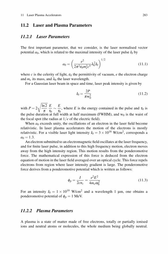
Fig. 11.4 Electrons spectra obtained at LULI. Left: in the laser beat wave scheme, right: in thelaser wakefield scheme
ωp =ω1−ω2 have been used to excite efficiently relativistic plasma waves. Withoutsaturation mechanism the amplitude of the plasma wave grows linearly with time:
δnn0
(t) =14√
a1a2ωpt (11.23)
where a1 and a2 are the force parameters of the laser beams. Due to the sharpresonance of the beat wave scheme any changes of the electron density reducesthe performance of this scheme. Limiting factors due either to relativistic effects oreither to ion motion have been observed. Beat wave experiments using a CO2 lasersat about 10 μm wavelengths or Nd lasers at about 1 μm wavelengths have shownelectric fields in GV/m order. In the CO2 lasers case the saturation of the electricfield was attributed to the relativistic detuning that occurs when the oscillationvelocity of the electrons is so high that the relativistic mass correction has to betaken into account and has to detune the plasma electrons from the pump beat waveterm. In the Nd case, experiments have been performed in plasmas with a higherdensity (ne = 1017 cm−3 instead of 1016 cm−3) that leads to a much faster couplingby modulational instability between electron waves and ion waves.
The first observation of relativistic plasma waves using Thomson scatteredtechnique [14] was performed at UCLA. Acceleration of injected electrons at 2MeV up to 9 MeV and up to 30 MeV has been demonstrated by the same UCLAgroup [15, 16]. Acceleration of electrons in a plasma beat wave experiments using1 μm lasers [17] has also been performed. Electrons injected at an energy of 3 MeVhave been accelerated up to 3.7 MeV in a plasma wave with a peak amplitude of2 % corresponding to a peak electric field strength of 0.6 GV/m. Electron spectraobtained at LULI in the laser beat wave scheme and in the laser wakefield schemeare shown on Fig. 11.4
In order to reduce the coupling between electron waves and ion waves whichwas a limiting factor of previous experiment done with 100 ps Nd lasers [18],experiments done at Rutherford Appleton Laboratory, with a 3 ps laser pulse haveshown excitation of higher amplitude relativistic plasma wave [19].
11 Laser Plasma Accelerators 291
Fig. 11.5 Evolution of the laser pulse and plasma density in the self modulated laser wakefieldregime
11.3.2 Non-Linear Regime
11.3.2.1 Self-Modulated Wakefield (SMWF)
Thanks to the development of powerful laser systems with short pulse duration (500fs), new non linear effects in plasmas has been studied. The cumulative effects of theself-focusing and the self-modulation of the laser envelope by the initial perturbationof the electron density generates a train of laser pulses which becomes resonant withthe plasma wave. These effects are described on Fig. 11.5. The self-modulated laserwakefield regime has been investigated theoretically [20–22]. Their works showthat when the laser pulse duration exceeds the plasma period and when the powerexceeds the critical power for self-focusing, a unique Gaussian laser pulse becomesmodulated at the plasma wavelength during its propagation. This mechanism,which is close to Forward Raman Scattering Instability, can be described as thedecomposition of an electromagnetic wave into a plasma wave at a frequency shiftedby the plasma frequency, that gives finally modulations similar to those produced inthe beat wave scheme [23]. In the experiment done at RAL, the relativistic plasmawave was exited by an intense laser (> 5× 10¹⁸ W/cm2), short duration (<1 ps),1.054 μm wavelength laser pulse in the self modulated laser wakefield regime. Thisinstability, induced by a noise level plasma wave of the strong electromagnetic pumpwave of the laser (ω0,k0) into plasma wave (ωp,kp) and two forward propagatingelectromagnetic cascades at the Stokes (ω0 − nωp) and anti-Stokes (ω0 + nωp)frequencies. n being a positive integer, and ω and k being the angular frequencyand the wavenumber respectively of the indicated waves. The spatial and temporalinterference of these sidebands with the laser produces an electromagnetic beatpattern propagating synchronously with the plasma wave. The electromagneticbeat exerts a force on the plasma electrons, reinforcing the original noise levelplasma wave which the scatters more sidebands, thus closing the feedback loop for
292 V. Malka
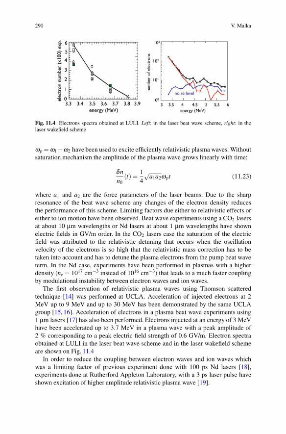
Fig. 11.6 Frequency and electron spectrum in the self modulated laser wakefield regime for twodifferent electron plasma densities : 0.54×1018 cm−3 (solid line and diamond symbols) and 1.5×1019 cm−3 (dashed line and circle symbols)
the instability. The solid curve in Fig. 11.6 shows the electromagnetic frequencyspectrum emerging form the plasma with a density of > 5 × 1018 cm−3 wherethe abscissa is the shift in frequency of the forward scattered light from the laserfrequency in units of ωp. The upshifted anti-Stokes and downshifted Stokes signalsat Δω/ωp = ±1 are clearly visible as is the transmitted pump at Δω/ωp = 0 andthe second and third anti-Stokes sidebands. These signals are sharply peaked, andtheir widths indicate that the plasma wave which generated these signals must have acoherence time of the order of the laser pulse. The dashed curve shows the spectrumwhen the density is increased to 1.5× 1019 cm−3. The most startling feature is thetremendous broadening of the individual anti-Stokes peaks at this higher density.This broadening corresponds to the wave-breaking and is mainly caused by the lossof coherence due to severe amplitude and phase modulation as the wave breaks. Aswave breaking evolves, the laser light no longer scatters off a collective mode ofthe plasma but instead scatters off the trapped electrons which are still periodicallydeployed in space but having a range of momenta producing, therefore a range ofscatter frequencies.
During experiments carried out in England in 1994 [2], the amplitude of theplasma waves reached the wave-breaking limit, where electrons initially belongingto the plasma wave are self-trapped and accelerated to high energies. The fact thatthe external injection of electrons in the wave is no longer necessary is a majorimprovement. Electron spectrum extending up to 44 MeV have been measuredduring this first campaign, and up to 104 MeV in the second campaign. This regimehas also been reached for instance in the United States at CUOS [24], at NRL [25].However, because of the heating of the plasma by these relatively ‘long’ pulses, thewave breaking occurred well before reaching the cold wave breaking limit, whichlimited the maximum electric field to a few 100 GV/m. The maximum amplitude ofthe plasma wave has also been measured to be in the range 20–60 % [26].
Experiments performed at LOA since 1999 have shown that electron beam canalso be produced using a compact 10 Hz laser system [27]. Figure 11.7 shows two
11 Laser Plasma Accelerators 293
Fig. 11.7 Left: Typical electron spectra obtained at 5×1019 cm−3 (squares) and 1.5×1020 cm−3
(circles). The corresponding effective temperatures are 8.1 MeV (2.6 MeV) for electron density of5× 1019 cm−3 (1.5× 1020 cm−3). Right: Maximum electron energy as a function of the plasmaelectron density. Experimental data: squares, theoretical value: line
typical electron spectra obtained at 5× 1019 cm−3 and 1.5× 1020 cm−3. The 0.6 J,35 fs laser beam was focused tightly 6 μm focal spot leading a peak laser intensityof 2× 10¹⁹ W/cm2. Electron distribution with electron energy greater than 4 MeVis well fitted by an exponential function, characteristic of an effective temperaturefor the electron beam. These effective temperatures are 8.1 MeV (2.6 MeV) forelectron density of 5× 1019 cm−3 (1.5× 1020 cm−3), to which correspond typicalvalues of 54 MeV (20 MeV) for the maximum electron energy. This maximumenergy is defined by the intersection between the exponential fit and the detectionthreshold. One can observe an important decrease of the effective temperature andof the maximum electron energy for increasing the electron densities.
This is summarised in Fig. 11.7 where we present the maximum electron energyas a function of the electron density. It decreases from 70 to 15 MeV when theelectron density increases from 1.5× 10¹⁹ to 5 × 1020 cm−3. Also presented inFig. 11.7 is the theoretical value [28]:
Wmax ≈ 4γ2p(Ez/E0)mc2FNL (11.24)
Here the maximum electron energy is greater than the conventional one, given bythe simple formula: Wmax ≈ 2γ2
p(Ez/E0)mc2, where γp is the plasma wave Lorentzfactor (which is equal to the critical density to electron density ratio nc/ne) andEz/E0 is the electrostatic field normalised to E0 (E0 = cmω p/e). The factor of twois due to self-channeling induced by space charge field which focuses acceleratedelectrons for all phases. The correction factor FNL ≈ (γ⊥0n0/n)3/2 correspondsto non linear correction due to relativistic pump effect and to self-channeling. Inthis formula n0 is the initial electron density and n the effective one, γ⊥0 is theLorentz factor associated to the laser intensity: γ⊥0 = (1+ a2
0/2)1/2. The electrondensity depression is estimated by balancing the space-charge force and laserponderomotive force, and evaluated by δn/n = (a2
0/2π2)(1+ a20/2)−1/2(λP/w0)
2.
294 V. Malka
Fig. 11.8 Density perturbation (top) and electric field (bottom) produced in the non linear regime
In the lower electron density case the depression correction will introduce animportant increase of the maximum energy gain which is multiplied by a factor of 2at 1.5×1019 cm−3. For density greater than 1.0×1020 cm−3, the main contributionis due to relativistic pump effect as is outlined on the plot in Fig. 11.7. It is alsocrucial to notice that the fact that the electron maximum energy increases when theelectron density decreases, demonstrates that electrons are mainly accelerated byrelativistic plasma waves. The maximum electron energy calculates at lower densityoverestimated the experimental ones indicating that the dephasing length becomesshorter than the Rayleigh length. In order to solve this problem, experiments wereperformed at LOA using a longer off axis parabola, more energetic electrons havebeen measured, with a peak laser intensity ten times smaller that in this firstexperiment. Electron beams with Maxwellian spectral distributions, generated bycompact high repetition rate ultra-short laser pulses, have been also at this timeproduced in many laboratories in the world: at LBNL [29], at NERL [30], and inGermany [31] for instance.
11.3.2.2 Forced Laser Wakefield (FLW)
The regime [32], is reached when the laser pulse duration is approximately equalto the plasma period and when the laser waist is about the plasma wavelength.This regime allows to reduce heating effects That is produced when the laser pulseinteracts with trapped electrons. In this regime highly non linear plasma wave canbe reached as one can see on Fig. 11.8.
The laser power needs also to be greater that the critical power for relativisticself focusing in order to the laser beam to be shrunk in time and in space. Dueto self-focusing the pulse erosion can take place, which can allow efficient wake
11 Laser Plasma Accelerators 295
Fig. 11.9 Typicalexperimental (squares) andcalculated (curve) electronspectrum obtained atne = 2.5×1019 cm−3 with a1 J-30 fs laser pulse focuseddown to a waist ofw0 = 18μm
generation. Since the very front of the pulse is not self-focused, the erosion will bemore severe. The wake then is mostly formed by this fast rising edge, and the backof the pulse has little interaction with the relativistic longitudinal oscillation of theplasma wave electrons. Indeed the increase of plasma wavelength due to relativisticeffects means that the breaking and accelerating peak of the plasma wave sits behindmost, if not all, of the laser pulse. Hence its interaction and that of the acceleratedelectrons with the laser pulse is minimised, thus reducing emittance growth dueto direct laser acceleration. Thanks to short laser pulses, plasma heating in theforced laser wakefield is significantly lower than in the self-modulated wakefield.This allows to reach much higher plasma wave amplitudes and also higher electronenergies as can be seen on Fig. 11.9. Thanks to a limited interaction between thelaser and the accelerated electrons, the quality of the electron beam is also improved.Indeed the normalised transverse emittance measured using pepper pot techniquehas given values comparable to those obtained with conventional accelerators withan equivalent energy (normalised rms emittance εn = 3π mm.mrad for electrons at55± 2 MeV) [33].
The 3-D simulations realised for this experiment shows that the radial plasmawave oscillations interact coherently with the longitudinal field, so enhancingthe peak amplitude of the plasma wave. This coupled with the aforementionedstrong self-focusing are ingredients absent from one-dimensional treatments of thisinteraction. Even in 2-D simulation, it was not possible to observe electrons beyond200 MeV, as measured in this experiment, since except in 3-D simulations, boththe radial plasma wave enhancement and self-focusing effects are underestimated.Hence it is only in 3-D simulations that Emax ∼ Ewb can be reached. That such largeelectric fields are generated, demonstrates another important difference betweenFLW and SMWF regimes, since in the latter, plasma heating by instabilities limitsthe accelerating electric field to an order of magnitude below the cold wave-breaking limit. It should be noted that the peak electric field inferred for these FLWexperiments is in excess of 1 TV/m, considerably larger than any other coherentaccelerating structure created in the laboratory.
296 V. Malka
Fig. 11.10 Left: Acceleration principle in the bubble regime, right: typical quasi monoenergeticelectron spectra measured at LOA
11.3.2.3 Bubble Regime
More recently, theoretical work based on 3D PIC simulations have shown theexistence of a robust acceleration mechanism called the bubble regime [34]. In thisregime, the dimensions of the focused laser are shorter than the plasma wavelengthin longitudinal and also transverse directions. Thus, the laser pulse looks like a ballof light with a radius smaller than 10 μm. If the laser energy contained in this volumeis large enough, the ponderomotive force of the laser expels radially efficientlyelectrons from the plasma, which forms a cavity free from electrons behind the laser,surrounded by a dense region of electrons. Behind the bubble, electronic trajectoriesintersect each other. Electrons are injected in the cavity and accelerated along thelaser axis, thus creating an electron beam with radial and longitudinal dimensionssmaller than those of the laser (see Fig. 11.10).
The signature of this regime is a quasi monoenergetic electron distribution. Thiscontrasts with previous results reported on electron acceleration using laser-plasmainteraction. This properties comes from the combination of several factors:
• The electron injection is different from that in the self-modulated. Injectiondoesn’t occur because of the breaking of the accelerating structure. It is localisedat the back of the cavity, which gives similar initial properties in the phase spaceto injected electrons.
• The acceleration takes place in a stable structure during propagation, as long asthe laser intensity is strong enough.
• Electrons are trapped behind the laser, which reduces or suppresses interactionwith the electric field of the laser.
• Trapping stops automatically when the charge contained in the cavity compen-sates the ionic charge.
• The rotation in the phase-space also leads to a shortening of the spectral width ofthe electron beam [35].
Several laboratories have obtained quasi monoenergetic spectra: in France [5] witha laser pulse shorter than the plasma period, but also with pulses slightly longerthan the plasma period in England [3], in the United States [4], then in Japan [36]
11 Laser Plasma Accelerators 297
Fig. 11.11 Principle of injection in the counter propagating colliding pulse scheme. (a) The twolaser pulses have not collided yet; the pump pulse drives a plasma wake. (b) The pulses collide andtheir interference sets up a beat wave that pre-accelerates electrons. (c) Preaccelerated electronsare trapped and further accelerated in the wake
and in Germany [37]. The interest of such a beam in important for applications:it is now possible to transport and to refocus this beam by magnetic fields. Witha Maxwellian-like spectrum, it would have been necessary to select an energyrange for the transport, which would have decreased significantly the electron flux.Electrons in the GeV level were also observed in this regime using in a uniformplasma [38] or in plasma discharge, i.e., a plasma with a parabolic density profile[39] with a more powerful laser which propagates at high intensity over a longerdistance.
11.3.2.4 Colliding Laser Pulses Scheme
The control of the electron beam parameters (such as the charge, energy, and relativeenergy spread) is a crucial issue for many applications. In the colliding schemesuccessfully demonstrated at LOA, it has been shown that not only these issues wereaddressed but also that a high improvement of the stability was achieved. In thisscheme, one laser beam is used to create the relativistic plasma wave, and a secondlaser pulse which, when it collides with the main pulse, creates a standing wavewhich heats locally electrons of the plasma. The scheme of principle of the collidinglaser pulses is shown in Fig. 11.11. The control of the heating level gives not onlythe number of electrons which will be trapped and accelerated but also the volume
298 V. Malka
Fig. 11.12 Longitudinal electric field computed at different times in 1D PIC simulation (solidline), and in fluid simulations (dotted line). The transverse electric field is also represented (thindotted line). Parameters are a0 = 2 and a1 = 0.4, 30 fs duration at FWHM and wavelengthλ0 = 0.8μm, electron plasma density 7 × 1018 cm−3. Left: parallel polarisation, right: crossedpolarisation
of phase space, or in other words, the energy spread of the injected electrons bunch[40]. In the pioneer work of Esarey et al. [41], a fluid model was used to describethe evolution of the plasma wave whereas electrons were described as test particles.Electron trajectories in the beat wave as well as their energy gain were derivedanalytically from theory in the case of laser pulses with circular polarisation. It hasbeen shown that this approach fails to describe qualitatively and quantitatively manyof the physical mechanisms that occur during and after the laser beams collision[42]. In the fluid approach, the electron beam charge has been found to be one orderof magnitude greater than the one obtained in PIC simulations.
For a correct description of injection, one has to describe properly (i) the heatingprocess, e.g. kinetic effects and their consequences on the dynamics of the plasmawave during the beating of the two laser pulses, (ii) the laser pulse evolution whichgoverns the dynamics of the relativistic plasma waves [43]. New unexpected featurehave shown that stochastic heating can be also achieved when the two laser pulsesare crossed polarised. The stochastic heating can be explained by the fact that forhigh laser intensities, the electron motion becomes relativistic which introduces alongitudinal component through the v×B force. This relativistic coupling makes itpossible to heat electrons. Thus, the two perpendicular laser fields couple throughthe relativistic longitudinal motion of electrons. The heating level is modifiedby tuning the intensity of the injection laser beam or by changing the relativepolarisation of the two laser pulses [44]. This consequently changes the volumein the phase space and therefore the charge and the energy spread of the electronbeam.
Figure 11.12 shows at different times the longitudinal electric field, during andafter collision for parallel and crossed polarisation. The solid line corresponds to thePIC simulation results whereas the dotted line corresponds to the fluid calculation.
11 Laser Plasma Accelerators 299
The laser fields are also represented by the thin dotted line. When the pulses have thesame polarisation, electrons are trapped spatially in the beat wave and cannot sustainthe collective plasma oscillation inducing a strong inhibition of the plasma wavewhich persists after the collision. When the polarisations are crossed, the motion ofelectrons is only slightly disturbed compared to their fluid motion, and the plasmawave is almost unaffected during the collision, which tends to facilitate trapping.Importantly it has been shown that this approach allows a control of the electronbeam energy which is done simply by changing the delay between the two laserpulses [6]. The robustness of this scheme has also allowed to carry out very accuratestudies of the dynamic of electric field in presence of high current electron beam.This beam loading effect has been used to reduce the relative energy spread of theelectron beam.
It has been shown that there is an optimal load which flattened the electric field,accelerating all the electrons with the same efficiency, and producing consequentlyan electron beam with a very small, 1 %, relative energy spread [45]. In this case, themore energetic electrons are slightly slow down and accelerated at the same energythat the slower one. In case of lower charge, this effect doesn’t play any role and theenergy spread depends mainly of the heating volume. For higher current, the load istoo high and the most energetic electrons slow down too much and get energies evensmaller that the slower one [45], increasing the relative energy spread. The optimalload was observed experimentally and supported by full 3D PIC simulations, itscorresponds to a current in the 20–40 kA. The decelerating electric field due to theelectron beam was found to be in the GV/m/pC range.
11.4 Future of the Laser Plasma Accelerators
Conventional accelerator technology has progressed through a long road paved byscientific challenges. A recent example is the development of superconductivityfor high current acceleration in RF cavity, which has required tens of years oftheoretical investigations and experiments to understand the physical processes andfinally to control the technology which has been successfully used in acceleratorssuch as LEP/LHC (CERN), or HERA (DESY-Hamburg). Laser plasma acceleratorresearches follow the same road paved with many successful (and unsuccessful)experiments. Thanks to this pioneering works and judging from the incredibleresults achieved over the last three years, the time has come where a technologicalapproach has to be considered. Two stages laser plasma accelerators schemesshould allow the development of few GeV electron beam with a small relativeenergy spread and a good emittance [46]. In parallel, theoretical and experimentalresearches should of course be pursued to explore new regimes and to validatetheories and numerical codes. The improvement of the laser plasma interaction withthe evolution of short-pulse laser technology, a field in rapid progress, will stillimprove this new and very promising approach which potential societal applicationsin material science, medicine, chemistry and radio-biology [47]. The ultra short
300 V. Malka
duration (few fs) of the electron beam [48], and consequently his very high current(few kA) comparable to the one delivers at SLAC for LCLS experiment, wherevery bright x-ray beams were produced by saturating the gain of their free electronlaser, indicate that laser plasma accelerators should play a significant role in thecompactness of free electron laser design and achievement.
Acknowledgements I acknowledge warmly X. Davoine, J. Faure, S. Fritzler, Y. Glinec, E. Lefeb-vre, A. Lifschitz, and C. Rechatin who have largely contributed during this last decade to the workI present in this book chapter. I also acknowledge the support of the European Research Councilfor funding the PARIS ERC project (contract number 226424), of the European Community-Research Infrastructure Activity under the FP6 and of European Community ‘Structuring theEuropean Research Area’ programs (CARE, contract number RII3-CT-2003-506395), of the ECFP7 LASERLABEUROPE/ LAPTECH Contract No. 228334, of the European Community-Newand Emerging Science and Technology Activity under the FP6 ‘Structuring the European ResearchArea’ program (project EuroLEAP, contract number 028514), and of the French national agencyANR-05-NT05-2-41699 ‘ACCEL1’.
References
1. T. Tajima, J.M. Dawson, Phys. Rev. Lett. 43(4), 267 (1979)2. A. Modena et al., Nature 377, 606 (1995)3. S. Mangles et al., Nature 431, 535 (2004)4. C.G.R. Geddes et al., Nature 431, 538 (2004)5. J. Faure et al., Nature 431, 541 (2004)6. J. Faure et al., Nature 444, 737 (2006)7. P. Mora, Phys. Fluids B 4(6), 1630 (1992)8. L.M. Gorbunov et al., Sov. Phys. JETP 66, 290 (1987)9. F. Amiranoff et al., Phys. Rev. Lett. 81, 995 (1998)
10. J.R. Marquès et al., Phys. Rev. Lett. 76, 3566 (1996)11. J.R. Marquès et al., Phys. Rev. Lett. 78(18), 3463 (1997)12. C.W. Siders et al., Phys. Rev. Lett. 76(19), 3570 (1996)13. N. Matlis et al., Nat. Phys. 2, 749 (2006)14. C.E. Clayton et al., Phys. Rev. Lett. 54, 2343 (1985)15. C.E. Clayton et al., Phys. Plasmas 14(1), 1753 (1994)16. M. Everett et al., Nature 368, 527 (1994)17. F. Amiranoff et al., Phys. Rev. Lett. 74, 5220 (1995)18. F. Amiranoff et al., Phys. Rev. Lett. 68, 3710 (1992)19. B. Walton et al., Opt. lett. 27(24), 2203 (2002)20. P. Sprangle et al., Phys. Rev. Lett. 69, 2200 (1992)21. T.M. Antonsen, Jr., P. Mora, Phys. Rev. Lett. 69(15), 2204 (1992)22. N.E. Andreev et al., JETP Lett. 55, 571 (1992)23. C. Joshi et al., Phys. Rev. Lett. 47, 1285 (1981)24. D. Umstadter et al., Science 273, 472 (1996)25. C.I. Moore et al., Phys. Rev. Lett. 79, 3909 (1997)26. C.E. Clayton et al., Phys. Rev. Lett. 81(1), 100 (1998)27. V. Malka et al., Phys. Plasmas 8, 2605 (2001)28. E. Esarey et al., IEEE Trans. Plasma Sci. 24(2), 252 (1996)29. W.P. Leemans et al., Phys. Plasmas 11(5), 2899 (2004)30. T. Hosokai et al., Phys. Rev. E 67, 036407 (2003)
11 Laser Plasma Accelerators 301
31. C. Gahn et al., Phys. Rev. Lett. 83(23), 4772 (1999)32. V. Malka et al., Science 298, 1596 (2002)33. S. Fritzler et al., Phys. Rev. Lett. 92(16), 165006 (2004)34. A. Pukhov, J. Meyer-ter-Vehn, Appl. Phys. B 74, 355 (2002)35. F.S. Tsung et al., Phys. Rev. Lett. 93(18), 185002 (2004)36. E. Miura et al., Appl. Phys. Lett. 86, 251501 (2005)37. B. Hidding et al., Phys. Rev. Lett. 96(10), 105004 (2006)38. N. Hafz et al., Nat. Photon. 2, 571 (2008)39. W.P. Leemans et al., Nat. Phys. 2, 696 (2006)40. C. Rechatin et al., Phys. Rev. Lett. 102(16), 164801 (2009)41. E. Esarey et al., Phys. Rev. Lett. 79, 2682 (1997)42. C. Rechatin et al., Phys. Plasmas 14(6), 060702 (2007)43. X. Davoine et al., Phys. Plasmas 15, 113102 (2008)44. C. Rechatin et al., New J. Phys. 11, 013011 (2009)45. C. Rechatin et al., Phys. Rev. Lett. 103(19), 194804 (2009)46. V. Malka et al., Phys. Rev. ST Accel. Beams 9(9), 091301 (2006)47. V. Malka et al., Nat. Phys. 4(6), 447 (2008)48. O. Lundh et al., Nat. Phys. 7, 219 (2011)