NASA CR -. 3346- v. 1 c.1 NASA Contractor Report 3346 Satellite Power Systems (SPS) Laser Studies Volume I: Laser Environmental Impact Study R. E. Beverly III CONTRACT NASS-32475 NOVEMBER 1980
Transcript
NASA CR
-. 3346- v. 1 c.1 NASA Contractor Report 3346
Satellite Power Systems (SPS)
Laser Studies
Volume I: Laser Environmental
Impact Study
R. E. Beverly III
CONTRACT NASS-32475 NOVEMBER 1980
TECH LIBRARY KAFB, NM
NASA Contractor Report 3346
Satellite Power Systems (SPS) Laser Studies
Volume I: Laser Environmental
Impact Study
R. E. Beverly III
Rockwell IutewlntiorzaI Cohn bus, Ohio
Prepared for Marshall Space Flight Center under Contract NAS8-3 2475
National Aeronautics and Space Administration
Scientific and Technical Information Branch
1980
. ..__ _._- ~~ _ ~~-
FOREWORD
This document, prepared in two volumes, presents the results of two laser studies performed as part of a Satellite Power System (SPS) study (NAS8-32475, for NASA/MSFC) during the period October 1978 through June 1980. Both studies were performed by Dr. R. E. Beverly, III.
The first study, Laser Environmental Impact (Subcontract M9M8BNB-896662D), is presented in Volume I of this document. The second study (Subcontract MOL8GNS-897409D), in two parts, Meteorologi.cal Effects on Laser Beam Propaga- tion and Direct Solar Pumped Lasers for the Satellite Power System, is presented in Volume II.
Special thanks are extended to the following people for assistance during the study activity resulting in Volume I of this technical report: Mr. Daryl J. Monson at NASA Ames Research Center for providing preprints of his work on CO lasers prior to publication; Professor K. Narahari Rao at the Physics Department of The Ohio State University for supplying high-precision spectroscopic data relative to CO laser transitions; and to Mr. David C. Applebaum, Dr. Russell H. Barnes, Jr., and Dr. Henry L. LaMuth at Battelle Columbus Laboratories for numerous technical discussions. The technical assistance given by Mr. Charles R. Agne and Mr. Steve A. Rohr of Control Data Corporation went far beyond the call of duty and is greatly appreciated. The discussions with Mr. A. I. Gordon of Rockwell International Corporation were extremely beneficial in guiding the present study.
If any questions regarding the technical content of these reports arise, please contact Dr. R. E. Beverly, III, at (614) 457-1242. Questions regarding the basic Satellite Power System program should be directed to either Mr. G. M. Hanley, Rockwell International, at (213) 594-3911, or Mr. A. I. Gordon, Rockwell International, at (213) 594-3687.
Single heat-exchanger thermodynamic cycle for closed-cycle EDL operation . . . . . . . . . . .
Dual heat-exchanger thermodynamic cycle for closed-cycle EDL operation . .
'+' - - * * - * * Energy level diagram 'of the Cg ground state of CO2 . . . Fractional population of the various CO2 levels as functions
of the gas-kinetic temperature . . . . . . . Comparison of the frequency/wavelength domains of low-
abundance CO2 isotope lasers with 12C1602 . . . . Absorption coefficients as a function of altitude for two
adjacent CO laser lines . . . . . . . . . Absorption coefficient as a function of altitude for
large-v CO laser lines . Output spectrum of a cw, cryogenically cooled (;7OKj * *
CO laser without line selection . . . . . . . Output spectrum of the same device with an intracavity line
selection cell filled with 400 Torr Hz0 . . . . . Output spectrum of the same device with an intracavity line
selection cell filled with 700 Torr H20 . . . . . The dependence of the total laser system efficiency, QL, on
the discharge efficiency using the thermodynamic models of a closed-cycle EDL . . . . . . . . .
Principal optical system candidates for a space-based laser transmitter . . . . . . . . . . . .
Fractional energy with the first Airy pattern dark ring as a function of the central obscuration ratio, E . . .
Clear air aerosol absorption and extinction coefficients as functions of wavelength for sea level transmission . .
Absorbing sphere concept . . . . . . . . . Laser-SPS system chain efficiencies . . . . . . CA as a function of altitude above sea level, h . . . Percentage of available power at the ground based site which
is intercepted within a specified receptor radius . . Continental wind velocity distributions as functions of
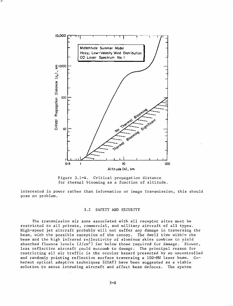
altitude . . . . . . . . . . . . Critical propagation distance for thermal blooming as a
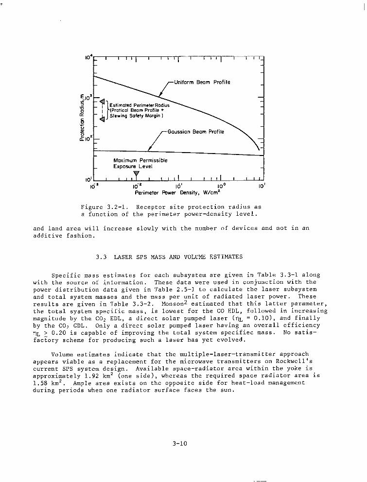
function of altitude . . . . . . . . . Receptor site protection radius as a function of perimeter
power-density level . . . . . . . . . . Fraction of transmitted laser power absorbed or scattered by
each atmospheric layer (Midlatitude Summer Model) . . Fraction of transmitted laser power absorbed or scattered by
each atmospheric layer (Midlatitude Winter Model) . . The concentration of electrons in the earth's ionosphere for
representative conditions . . . . . . . .
2-2
2-6 2-8
2-9
2-11
2-12
2-13
2-14
2-14
2-15
2-16
2-18
2-19
2-25 2-32 2-33 3-4
3-5
3-7
3-8
3-10
4-2
4-2
4-6
IV
Figure Page
4.3-2 Altitude dependence of energy absorption and emission . . 4-9 4.4-l Schematic representation of the formation of positive ions
in the D-region . . . . . . . . . . . 4-14 4.4-2 Schematic representation of the formation of negative ions
in the D-region . . . . . . . . . . . 4-14 4.4-3 Calculated positive-ion concentrations in the D-layer at
70 km for a day in which the noonday sun is overhead . 4-15 4.4-4 Calculated negative-ion concentrations in the D-layer at
70 km for an ordinary day in which the noonday sun is overhead . . . . . . . . . . . . 4-15
V
Table
TABLES
Page
2.1-l 2.1-2 2.2-l 2.3-l 2.3-2 2.3-3 2.3-4
2.3-5
2.3-6
2.4-l
2.5-l
3.3-l
3.3-2 4.3-l 4.4-l 4.4-2
Isotopic species of carbon dioxide . . . . . . . CW discharge characteristics . . . . . . . . Transmitting optical system specifications . . . . . U.S. standard model atmosphere: Midlatitude Summer . . U.S. standard model atmosphere: Midlatitude Winter . . Abundance of uniformly mixed gases in the atmosphere . . Atmospheric transmission efficiencies for 12C1802 laser
transitions using the midlatitude summer model and 8 = 50" Atmospheric transmission efficiencies for CO laser transi-
tions using the Midlatitude Winter and Continental Aerosol models for a zenith angle 8 = 50" . . . . . .
Atmospheric transmission efficiencies for CO laser transi- tions using the Midlatitude Summer and Continental Aerosol models for a zenith angle 6 = 50" . . . . . .
Candidate receptor concepts for conversion of ir radiation into electricity . . . . . . . . . .
Electrical, mechanical, and thermal power distribution for a laser SPS employing a supersonic CO EDL . . . . .
Subsystem and total system mass estimates . . . . . Ionospheric parameters . . . . . . . . . . Species of importance to the sub-D- and D-regions . . . Photoreactions involving charged species found in the D-
region which may be induced by an intense ir-photon flux
2-11 2-16 2-20 2-23 2-24 2-25
2-26
2-27
2-28
2-30
2-34
3-11 3-11 4-6 4-13
4-16
vi
1.0 INTRODUCTION
Solar Powered Satellites (SPS) are currently under consideration by NASA as civilian electric power sources. Power derived from the continuous solar flux is converted to electricity via photovoltaic cells, beamed to earth as microwave radiation, and then converted back into electricity for distribution by commercial electric power grids. Due to concerns about the environmental implications and potential biological hazards of long-term, low-level micro- wave radiation, alternate power beaming approaches are being considered, principally lasers.lp2
The primary emphasis of this research is on the environmental impact of space-to-earth power transmission using lasers. Before this is undertaken, it is necessary to define the laser system and the complementary ground based receptor. Estimates of the relevant efficiencies for laser power generation, atmospheric transmission, and receptor electrical conversion enable a compari- son with the microwave based SPS. Ancillary issues such as laser beam spread- ing , safety and security, mas and volume estimates, and technology growth projections must be considered to fully bound the operational limits and char- acteristics of the laser-SPS system. This report summarizes the study performed to define the laser-SPS concept (Task l), to address important ancillary issues (Task 2), and to assess the environmental impact of space-to-earth power trans- mission using lasers (Task 3). The concluding section of this report summarizes important findings and recommends further research in the areas of advanced laser development and atmospheric effects of laser power transmission. Propon- ents of the free-electron laser have suggested its use in space-based power transmission schemes; for this reason, a cursory review of this laser is given in the appendix.
The two major guidelines specified by Rockwell have been followed in this research study. This conformance will permit Rockwell to perform a subsequent comparative analysis between laser- and microwave-based SPS concepts. Specific- ally, (1) the operational attitude and orbit to be considered will be geosynch- ronous equatorial orbit (GEO) with laser-beam pointing at typicai U.S., midlatitude receptor sites, and (2) the individual subsystems or cluster power sources of the laser SPS will be capable of being grouped at a single location in GE0 and operated as a single laser-beam generator capable of consuming, as input power, the entire power output of the baseline photoelectric power source (9.4 GW). Slant ranges to typical receptor sites in the U.S. from a laser in GE0 at an altitude of 35,786 km will be taken to be 42,700 km. The zenith angle of the laser beam pointing at earth, 8, is taken to be 50".
In terms of efficiency, scalability, reliability, and atmospheric propa- gation, two molecular-gas electric-discharge lasers (EDL's) have been suggested for their potential in space-to-earth power transmisswon systems, namely, the CO and CO2 lasers. Both types have received extensive support in terms of high-. power military applications, and both are documented by a large quantity of pub- lished and unpublished literature. Based on the present evaluation of CO and
l-1
CO2 EDL's for operation in space, the laser-SPS system efficiency, defined as the ratio of power availability at the user grid to power produced by the solar photovoltaic array, is the largest for the CO EDL system. Furthermore, the laser system mass is lowest and the environmental impact is less if a COL EDL is employed for power transmission rather than a CO2 EDL.
l-2
2.0 CONCEPT DEFINITION
2.1 EVALUATION OF ELECTRIC-DISCHARGE LASERS
2.1.1 CLOSED-(SYCLE THERMODYNAMIC MODELS
We consider molecular-gas high-power lasers in which the excitation process is an electric discharge and the gas is circulated in a closed cycle. Gas circ-
'ulation permits removal of waste heat, and closed-cycle operation minimizes the rate of gas consumption, allowing long periods of operation. In general, the laser gas mixture consists of a small amount of lasant, such as CO or Cop, added to a diluent such as He, Ne, Ar, N2, or mixtures thereof.
The most important parameter characterizing a large-scale laser is the total system efficiency, nL defined as
pL nL 7 Pps + PM ' (1)
where PL is the laser power output, and PpS and PM are the electrical power inputs required by the excitation power supply(ies) and gas compressor motor. The electrical power deposited into the gas, PE, is related to the electrical power input to the discharge power supplies by
pE = nPspPs ' (2)
where nPS is the intrinsic power supply efficiency. Similarly, the compressor power, PC, is related to the electrical power input to the compressor motor by
where nM is the intrinsic motor efficiency. The most oftenly quoted efficiency in experimental laser studies is the discharge efficiency, nd, defined as the ratio of laser output power to electrical power deposited into the gas, i.e.,
rid = PL/PE . (4)
Substituting Equations (2) through (4) into Equation (1) and rearranging yields
rl n =
L (lh-,ps) +d(pcip,)l M - (5)
Knowing nPS and nM, and inferring nd from experimental or theorgetical studies of EDL's, only the ratio of compressor power to electrical power deposited into
2-l
the gas, PC&, is needed to calculate nL. This ratio is calculated in the thermodynamic analysis described below.
We follow closely the purely thermodynamic treatments of Monsqn 2,3 and Burns.4 Two different closed-cycle laser systems are postulated, and the system efficiency is calculated over a range of realistic parameters. For a CO EDL, a low gas-kinetic temperature is required to achieve lasing on low vibrational quantum number bands and to maximize the discharge efficiency. The former requirement is necessary for efficient atmospheric transmission, since only the shorter wavelength lines are not strongly absorbed. For a CO2 EDL, gas-kinetic temperatures lower than ambient are required for operation on non-standard lasing transitions, also for reasons of efficient atmospheric transmission. Isentropic expansion in a supersonic nozzle is used to achieve the,desired static temperature. The explicit details of the discharge and extraction mech- anisms are of no interest to these calculations.
Consider the first thermodynamic cycle shown in Figure 2.1-1. In the plenum, the gas has a stagnation temperature T,-,l, a stagnation pressure Pal, and a Mach number of approximately zero. The gas is accelerated through a
PO1 PO1
To1 PO2
TO1 M = M, To2
1 t
PE PL PO2
To2
9y (to space radiator1 hl=O
I To3
Figure 2.1-l. Single heat-exchanger thermodynamic cycle for closed-cycle EDL operation
2-2
supersonic nozzle to a Mach number Ml and a static temperature Tr at the entrance to a constant-area laser channel. In this region, excitation power PE is added to the gas by a glow discharge. A certain fraction of this excitation power, nd, is extracted from the optical cavity as laser power output, PI. The excita- tion power that is not extracted remains in the gas and eventually goes into gas heating. Now in this simplified cycle, we consider the particular case where enough power is added to the gas so that the Mach number at the laser channel exit is unity, i.e., the flow is choked. This gives the minimum mass flow and compressor power for any given laser power output and, as such, repre- sents an idealized situation which permits ease of calculation without the complication of additional gas-dynamic parameters. These conditions will not be realized in any practical device, in which the power added must be consistent with the discharge stability limits and with the maximum temperature increase allowable by lasing kinetics. Thus, the simplications and restrictions of the present model yield an upper limit to the predicted performance and, as such, represent an optimistic situation which may only be approached with realistic devices. Because of heat addition, the stagnation pressure decreases to PO2 and the stagnation temperature increases to T02at the channel exit. The gas then enters a subsonic diffuser where it is decelerated to approximately zero Mach number, flows through various ducts where frictional and turning losses drop the stagnation pressure further to POT, and flows through a compressor which adiabatically compresses the gas back to the original stagnation pressure Po1 and an elevated stagnation temperature T03. The power added to the gas is WC 3 Ghere nc is the compressor adiabatic efficiency and PC is the power required to drive the compressor. Finally, the gas flows through a waste heat exchanger which reduces the stagnation temperature back to the original value, To1 . QW is the quantity of heat removed from the gas by a single heat exchanger which must be radiated away into space. Note that placing the heat exchanger before the compressor reduces the required compressor power, but at the expense of a much larger radiator area.
The thermodynamic and flow equations that describe the cycle shown in Figure 2.1-l are now developed. Assuming isentropic supersonic expansion, the static temperature at the entrance to the discharge cavity is
(6)
With the assumption of choking at the laser channel exit, the stagnation pres- sure and temperature ratios follow from standard relations for heat addition in a constant-area duct,5 i.e.,
po2= (1 + ~$1 pO1 (Y + 1)
r 1 Y+l
2(1 + q Mf)
T02 - (1 + YM;"
T01 2(y + l)M;(l + 9 Mf)
I * I (7)
(8)
2-3
Monson2 estimates the pressure drop due to frictional and turning losses between the diffuser and compressor by the quasi empirical expression
;(I; _ [ 0.7T++ll.25] '. (9)
The pressure drop across the heat exchanger is ignored, since it is assumed to be negligible compared with the loss across the laser.
For adiabatic compression, the compressor power is given by the standard expression
(10)
. where m is the gas mixture flow rate, n, is the adiabatic efficiency of the compressor, and Cp is the specific heat at constant pressure. If we assume that the only power lost from the gas is that of the output beam, PI, and that the specific heat at the laser channel exit equals that at the inlet, then the heat added to the gas by excitation, QH, is given by
Q, = kCp(To2 - Tel> = PE - PL = (1 - nd)PE . (11)
The second assumption is not strictly true, since C f:
is a function of the rota- tional and vibrational temperatures of the lasant; owever, since the lasant gas comprises a minority fraction of the total gas composition (typically a few percent to 10 percent), this effect is negligible in terms of the gas-dynamic calculation presented here. From Equation (ll), the mass flow rate is
(1 - m- 'dlPE .
(12)
CpTOl
Substituting Equation (12) into Equation (1)) and rearranging gives and equation for P,/PF in terms of known efficiencies and stagnation states:
pc -= pE
(1 - nd) (To2/Tol)
rl --
r
2-4
Here, the stagnation state ratios depend only on y and Ml and are computed from Equations (7) through (9). The total laser system efficiency, nb, is thus obtained by substitution of Equation (13) into Equation (5).
Waste heat is removed from the flowing gas by the heat exchanger and sub- sequently radiated away into space. The required radiator area, A,(m'), is given by
Qw AL.==3 03
where E is the radiator surface emissivity (assumed to be 0.85) and o is the Stefan-Boltzmann constant (5.6686~10~~ W/m2 - OK4). In Equation (14) we assume radiation to deep space (sink temperature + 3'K) and ideal heat-exchanger effectiveness. The waste heat, Qw, is
Q, = PE -PL+nP cc'
which may be rewritten in terms of the known and calculated efficiency par- ameters as
Q, = -& - 1 + r,Mnc 1 - - 'd 'dnPS pL (16)
The radiator temperature, To3, is simply
To3 To3 Toz = - . - . To1 , To2 TOI
where Tolis the plenum stagnation temperature, the ratio To~/To~ is given by Equation (8), and the ratio To~/To~ is found from the equation
(4 y-l T03= po1 y
T02 po3
(2 1 -) y-l
-. po3 y po2
. (17)
The stagnation pressure ratios needed in Equation (17) were derived previously in Equations (7) and (9).
The second thermodynamic cycle, shown in Figure 2.1-2, uses two waste heat exchangers. This cycle is identical to the previous one, except that a second heat exchanger is placed ahead of the compressor to cool the gas back to the initial stagnation temperature, Tol. Monson2 found that this second con- figuration reduces the compressor power but increases the required radiator area. The net result, however, is a reduction in the total system specific mass and an improvement in system efficiency.
2-5
PO1
PO1 To1 PO2
TO1 M-M, To2
M= 0 M=l
I y. 1
PO1
To1
Plenum Discharge Subsonic Cavity Diffuser -
I
PE PL
WaSta - Hsat
EXdUllgW --f Q2 (to space radiator)
A PO1 4y, (to space radiator)
To3 t
Waste Compressor e Hmt -
PO3 Exchanger PO3
t
To1 To2
%Pc
PO2
To2
hl=O
Figure 2.1-2. Dual heat-exchanger thermodynamic cycle for closed-cycle EDL operation.
The thermodynamic analysis proceeds in an identical manner to that employed for the first cycle. Without showing all of the details, we obtain an alternate expression for the ratio of compressor power to excitation power, namely,
r 1
1 .
Substituting Equation (18) into Equation (15) yields the appropriate expression for QL. The stagnation state ratios, T02/T01, P02/P01, and P03/Po2, are identi- cal to those employed in the first cycle. The expression for the radiator area is now
(19)
2-6
and the waste heat terms are
and
(7-O)
Two different temperatures are associated with the two waste heat sources, i
T n7 (22)
and
T03 =3LT
T01 O1 (23)
Toi is again the plenum stagnation temperature, T&To1 is given by Eq. (S), and To3/Tol is found by solving the equation
T03 T01
=
(z. pm)* I
(24)
e.,
where Po2/Po1 and Po3/Po2 are given by Equations (7) and (9) as before.
2.1.2 CO2 LASER EVALUATION
Several research groups have suggested using CO2 EDL's for power trans- mission. A highly evolved technology base exists, and device scaling to powers of the order of 100 MW is reasonably well assured. Significant operational experience with closed-cycle systems has been gleaned over the past few years. With CO2 EDL's, most conceptual systems employ subsonic flow to remove waste heat from the gas mixture; consequently, less compressor power is required as compared with supersonic operation. Advocates of the CO2 EDL cite this fact as a major advantage and quote rather high laser system efficiencies (-25%). As discussed in the following paragraphs, this conclusion is inaccurate and neglects several important physical phenomena.
Under normal circumstances, lasing with the CO2 molecule can occur between the asymmetric stretch and symmetric stretch modes (00' + 10'0) or the asymmetric stretch and bending modes (00'1 + 02'0). The laser wavelength is -10.4 pm or -9.4 pm, with the exact wavelength depending upon the details of the respective rotational sublevels. The cogent energy levels are shown in Figure 2.1-3. The
2-7
0 VI
1 Symmetric Stretch 1
v2 (Bending)
y2 (Asymmetric
Stretch)
0.3
0.2 2 B s i w
0.1
0
Figure 2.1-3. state of CO2.
Energy level diagram of the 1: ground Higher lying levels and the rotational
fine structure associated with each vibrational level are omitted for clarity.
00'1 state is pumped by direct electron impact or by resonant transfer of vibra- tional energy from N2. Thus, N2 is usually one gas constituent in a CO2 EDL. To avoid a cessation of lasing, excess population buildup in the 0110 level must be removed by collisional relaxation. Helium, also a constituent in CO2 laser gas mixtures, serves to depopulate this level and to act as the heat transfer medium.
Because the 0110 state is energetically close to the'ground state, it is easily filled by thermal excitation. When this occurs, bottle-necking of the laser transition causes a loss in.population inversion and eventually a complete loss in output power. Figure 2.1-4 is a plot of the fractional population of the various CO2 levels as functions of gas temperature. The two cross-hatched regions identify the conditions under which population inversions on the 9.4- and 10.4-urn transitions are permitted. The two curves denoted by AN show the dependence of inversion population on temperature. An inversion cannot be maintained on the 00'1 + 02'0 band (9.4 urn) for temperatures greater than- 400"K, or on the Op"l + 10'0 band (10.4 pm) for temperatures greater than- 700°K. To obtain good discharge efficiencies in large devices, the static temperature of the inlet gas should be much lower, ~200°K and -4OO'K, respectively.
The atmospheric transmission efficiency of any line within the 00'1 -f 10'0, 10.4-urn band has been calculated to be very poor. To alleviate this situation
2-8
/ Al / AN(10.4pm)JY \ -
\ AN (9.4pm)
lc? I I 1
0 100 200 300 400 600 600 700 Temperoture, OK
Figure 2.1-4. Fractional population of the various CO2 levels as functions of the gas-kinetic tempera- ture, assuming that 3% of the available CO2 molecules are maintained in the 00'1 state.
various transitions within the OO"1+0200, 9.4-urn band have been suggested. If low-abundance isotopic species of CO2 are employed as the lasant, a shift in output wavelength occurs and atmospheric absorption features due to natural CO2 can be avoided.
It is desirable to calculate the maximum theoretical efficiencies for CO2 lasers operating under these conditions. Using the energy level diagram (Figure 2.1-3) it is straightforward to calculate system quantum efficiencies. The OO"l+lOoO transition at 10.4 urn has a quantum efficiency of 40%, while the OO"1+0200 transition at 9.4 urn has a quantum efficiency of 45%. The maximum electric power transfer to the coupled C02(00°1)-Nz(v) system is about 70%, ribh the remainder going into ionization, electronic excitation, and translation. 9 Hence, the maximum achievable discharge efficiencies are simply
lid (9.4 urn) = 0.45x0.70 = 0.32,
'ld (10.4 urn) = 0.40x0.70 = 0.28.
2-9
Therefore, if the power required to maintain the closed-cycle flow is small, overall laser systems efficiencies exceeding 20% are reasonable.
As noted above, a static gas temperature as low as 200°K is required for operation on the OO"1+0200 band. Two cooling methods are available for a space- based laser. The laser cycle can be operated subsonic using space radiators to cool the gas emerging from the discharge to -2OO'K before re-entering the excitation region. Because of the low temperature required, a huge radiator surface area would be necessary. Alternately, high plenum temperatures are permissible to reduce the required radiator area if a supersonic expansion is used to obtain the low static gas temperature.
Thermodynamic calculations were performed for such a closed-cycle, super- sonic CO2 laser using the thermodynamic models developed previously and the following plenum stagnation temperature and subsystem efficiencies:
POI i= 360°K
qc = 0.85 rl ps = 0.9323
qM = 0.8950 .
This procedure permits a direct compar ,ison of CO2 and CO laser systems effici- encies (see Figure 2.1-11). Using a mixture consisting mostly of He (y = 1.65), a static gas temperature, Tl, of 200°K requires a flow Mach number of
Ml = 1.57
Under these conditions and with a discharge efficiency of 0.32, the total laser system efficiency for operation on the OO"1+0200, 9.4-urn band is
'1L = 0.135 (1 HEX)
rlL = 0.141 (2 HEX)
The total laser system efficiency is defined as the ratio of laser output power to total electrical power required to operate the system. Operation with two heat exchangers affords little improvement in overall system efficiency for these conditions.
To affect maximum atmospheric transmission, lasing on only one specific vibrational-rotational line is being considered. In the analysis above, rota- tional relaxation effects have been ignored, which leads to an overprediction in the discharge efficiency. Hence, the total system efficiency estimates may be somewhat optimistic.
In this context, the laser would be arranged in a MOPA (Master Oscillator Power Amplifier) configuration in which a small grating-tuned oscillator drives a large power amplifier. The oscillating spectral line is selected by adjusting the grating angle on the oscillator. This technique avoids the use of large, expensive, and delicate gratings with high-power oscillators.
2-10
The wavelength range of the two principal lasing bands using several dif- ferent CO2 isotopic species is shown in Figure 2.1-5. The line identified by Mevers et al.ll with the best atmospheric transmittance is the R(20) line of the OO"1+0200 band of 12C'*02. The natural abundances of the various isotopic
I II I II II I I I I II I I IllI I 11 I1 I I I I I I 1
WAVE NUMSER km-‘J
_I - __~.. 1 - I I I I So 9.5 10.0 la5 11.0 115
WAVELENGTH (pm)
Figure 2.1-5. Comparison of the frequency/wavelength domains of low-abundance CO2 isotope lasers with 12C1602 (References 9 and 10).
species of CO2 are given in Table 2.1-1. If a specific isotopic specie of carbon dioxide is required for acceptable atmospheric transmission, then some method of isotope separation must be employed. If "C'aO2 is chosen as the lasant specie, added expense will be incurred due to the recovery process because of this specie's extremely small abundance. (Actually, only the 0.2% of the '*O in elemental oxygen would require separation; the "0 thus separated would then be reacted with natural carbon, which is 98.89% 12C.) Recall that the separative work in isotope separation, however, is proportional to the isotopic mass difference divided by the abundance-weighted mass. Hence, separ- ation of "0 from oxygen will take far less work than separation of 2351J from uranium; thus, the separative cost may not be prohibitive in such a specialized laser application.
Table 2.1-1. Isotopic species of carbon dioxide.
Species Natural Abundance
~-~
=‘c==oP 93.14::
1'C'60* 1.105%
irC1'O* 0.000418
"C1'On 0.0000046~
2-11
2.1.3 CO LASER EVALUATION
The lasing spectra of CO lasers show a characteristic multiline output whose distribution is a function of the gas-kinetic temperature. In large- scale devices, the low gas-kinetic temperature of the lasing medium is achieved by a supersonic expansion. This results in lasing on low v transitions and improved atmospheric transmission. The spectral output above ~5.4 pm is strongly absorbed by the atmosphere.
The atmospheric transmission efficiency is a sensitive function of the multiline distribution, and any calculation of atmospheric transmission of CO laser radiation must be performed by weighting the line transmittance by the fractional laser power in each line and then summing over all the lines. As shown in Figures 2.1-6 and 2.1-7, the absorption coefficients for the longer wavelength (larger v) transitions are much larger than for shorter wavelength transitions. 12 Large differences also can exist in the absorption coefficients of adjacent lines. Since a large fraction of the molecular absorption is attributable to the 6.3-urn water band, seasonal variations are pronounced. Due to a significant improvement in atmospheric transmission of the lower v transitions, much effort has been expended in developing laser devices which maximize their power output on such transitions.13
IO2 1
Midlatitude Summer - --- Midlotitude Winter
v'-v = 6-5, P(lI)
VI-J= 6-5, P(I0)
Figure 2.1-6. Absorption coefficient as a function of altitude for two adjac- ent CO laser lines. 12
Altitude, km
2-12
v'+v=l3*12, P(IO) -
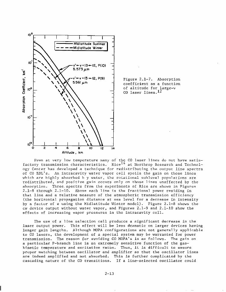
v'-cv=13-~12, P(9) Figure 2.1-7. Absorption coefficient as a function of altitude for large-v CO laser lines.12
Altitude , km
Even at very low temperature many of the CO laser lines do not have satis- factory transmission characteristics. Rice14 at Northrop Research and Technol- ogy Center has developed a technique for redistributing the output line spectra of CO EDL's. An intracavity water vapor cell spoils the gain on those lines which are highly absorbed b y water, the rotational sublevel populations are redistributed, and positive gain occurs only on those lines unaffected by the absorption. Three,spectra from the experiments of Rice are shown in Figures 2.1-8 through 2.1-10. Above each line is the fractional power residing in that line and a relative measure of the atmospheric transmission efficiency (the horizontal propagation distance at sea level for a decrease in intensity by a factor of e using the Midlatitude Winter model). Figure 2.1-8 shows the cw device output without water vapor, and Figures 2.1-9 and 2.1-10 show the effects of increasing vapor pressures in the intracavity cell.
The use of a line selection cell produces a significant decrease in the laser output power. This effect will be less dramatic on larger devices having longer gain lengths. Although MOPA configurations are not generally applicable to CO lasers, the development of a special system may be warranted for power transmission. The reason for avoiding CO MOPA's is as follows. The gain on a particular P-branch line is an extremely sensitive function of the gas- kinetic temperature and excitation rates. Thus, it is difficult to ensure proper matching between oscillator and amplifier so that the oscillator lines are indeed amplified and not absorbed. This is further complicated by the cascading nature of the CO transitions. If a line-selected oscillator could
2-13
4.9 5.0
a!xl 2ml
I rz 4
WAVELENGTH (pm) 5. 1 5.2 5.3 5.4 5.5 5.6
a. 4% 1950 19tQ 1850 1800 .5km) FREQUENCY (cm-‘)
ml
rl"
4. PI0 .2km)
5 tml
11. IO. 1 11
LINE SELECTION CELL
PIH20) = 0.0
PICOI . 0. 08
PIN21 = 1. 40
P(02J - 0.m
1. 2% 13.92kml
1 5.4% Il. 35km)
I.-3..oa I
Figure '2.1-8. Output spectrum of a cw, cryogenically cooled (77°K) CO laser without line selection.14
4.9 5.0
xl50 m3l
21 (3.
r. m)
-I-
6
-
1
WAVELENGTH (pm1 5. 1 5.2 5.3 5.4 5.5 5. 6
19M 1900 l&l lsbo 31.990 4.49km)
FREWENCY (cm-‘1 LINE SELECTION CELL
PlH201 * 403 Torr @ 1dC
L lo -5
rt7
2- i
Ib :ml
12.2% (4. Fdkml
I
PT = 5.85Torr
PICO) = 0.08
PIN21 . 1.40.
P(02) - 0.006
PtHel = 4. 37
I = 2.OmA
= 240 mW
Figure 2.1-g. Output spectrum of the same device shown in Fig. 2.1-8 with an intracavity line selection cell filled with 400 Torr H~0.l~
2-14
WAVELENGTH (pm) 4.9 5.0 5. 1 52 5.3 5.4 5.5 5.6
xi50 ail 19M lial - 1ikI 18bl FF
-1
..+.A? . iEPUENCY km ‘I
LINE SELECTION CELL tnw~rn,
PIH201 = 7W Torr @ l!Xk
Figure 2.1-10. Output spectrum of the same device shown in Fig. 2.1-8 with an intracavity line selection cell filled with 700 Torr H20.14
be designed in conjunction with a large power amplifier, then the loss in dis- charge efficiency due to the presence of an intracavity cell would be minimized.
In closed-cycle flow, the compressor power required to circulate the gas is a function of the flow Mach number. Thus, operation at the low gas-kinetic temperatures necessary for efficient atmospheric transmission requires a sub- stantial fraction of the total power available just to operate the flow cycle. The dependence of total laser system efficiency, nL, on the discharge effici- ency for two thermodynamic cycles is shown in Figure 2.1-11. The shaded region denotes the range of expected performance. To achieve the necessary low static temperature in the discharge cavity, a supersonic expansion of Mach number 3 to 4 is required based on the anticipated plenum stagnation temperature of approximately 360'K. Discharge efficiencies of 0.35 to 0.50 appear possible. Mann15 has suggested that discharge efficiencies of 0.60 in cw devices may be achievable; however, the best reported16 performance is 0.39. The thermodynamic cycle with dual heat exchangers affords and improve- ment in system performance over the cycle with a single heat exchanger. As noted in Figure 2.1-11, the potentially achievable laser system efficiency ranges from 11.5% to 23.4T. In the discussions which follow, we assume best- case performance, i.e., rlL = 0.234.
2.1.4 ELECTRIC DISCHARGE TYPES
The type of electric discharge employed in conjunction with a molecular gas laser influences most system parameters (e.g., nd and nL) while effecting many ancillary characteristics such as reliability, serviceability, system
2-15
444
Tc = 0.8500 71~ = 0.8950 q,s= 0.9323 y = 1.645 (5% CO in He) /’ -
Single Heat Exchanger / ?= 3.00 - - - -Dual Heat Exchanger / Figure 2.1-11. The dependence
of the total laser system effi- - ci-7, 77~~ on the discharge
efficiency using the thermo- dynamic models of a closed- cycle EDL.
mass and volume, and scalability. Quantitative characteristics of the various discharge types are listed in Table 2.1-2. Based on our evaluation, the pulser- sustainer type of discharge has many attributes which make it suitable for the present application and deserving of more research support.
Table 2.1-2. CW discharge characteristics.
Discharge Type
Characteristics Suitability
Advantages Disadvantage& co CD2
Self-sustained dis- Simple, reliable, highly Low to moderate dis- NO Yes charge evolved technology; scaling charge efficiency: low
behavior well understood specific and volumetric power loadings
Non-self-sustained discharge
(1) Electron-beam- Improved discharge efficiency: Poor reliability, x-ray YfS Yes sustained high specific and volumetric hazards, complex mainte- discharge power loadings, scaling nancc: c-beam trans-
behavior understood mission foil blow out leads to a loss of lasant gases
(2) Pulser- sustainer discharge
Less complicated and smaller Scalability to larqc de- Yes Yes than e-beam sustained devices; vices not demonstrated, comparable volumetric and discharqc efficiencies specific power loadings may be comparable to e-beam- possible with further research; susthined devices not yet promises to be more reliable. achieved; technology not
highly evolved.
2-16
Molecular-gas electric-discharge lasers operate at maximum discharge effi- ciency only within a certain range of the parameter E/N (electric-field strength divided by the neutral species concentration). This range depends only upon the gas mixture composition. With a self-sustained glow discharge, the rates of electron production (e.g., ionization) and electron destruction (e.g., recombin- ation, attachment, etc.) are electron-temperature dependent and adjust them- selves until equality is reached. This may lead to discharge operation outside the range of optimum E/N and a concomitant loss in discharge efficiency. The CO EDL is a particularly good case in point, since the optimum E/N is lower than that required to maintain ionization in the plasma. To alleviate this situation, various non-self-sustained discharge schemes have been developed in which the ionization "source" and sustainer electric field are separate. The rates of ionization and electron-impact excitation are effectively decoupled, allowing independent control of E/N; hence, maximum discharge efficiency can be obtained.
The utilization of a non-self-sustained discharge with a CO2 EDL is less critical. However, for both types of moiecular-gas lasers, the specific power loading, PE/m (kW/kg/sec or kJ/kg), and volumetric power density <jE> (W/cm3), are improved when a non-self-sustained discharge is employed. [Here, j is the discharge current density (A/cm2> , E is the electric field strength (V/cm2), and the other terns were defined previously.]
The pulser-sustainer, or "POKER", discharge was originally investigated by Reilly17 in conjunction with a subsonic pulsed CO2 laser. Later, Hi1118 applied the technique to a cw CO2 laser by superimposing a train of high-voltage breakdown pulses upon the low-voltage dc sustainer field. Although interest in the pulser-sustainer CO2 laser has waned in the United States, Soviet researchers
ge;;:;;z:3 pursuing this technique in conjunction with subsonic19-24 and devices. Their stated intent is the development of non-electron-
beam cw gas lasers for industrial materials processing applications.
Research on pulser-sustainer discharges applied to supersonic-flow CO lasers has been conducted at the Air Force Weapons Laboratory26 and at NASA/ Ames Research Center.27y28 The later experiments of Monson28 are particularly significant since they indicate discharge performance comparable to electron- beam-stabilized discharges with device scale-up. The pulser-sustainer type of discharge avoids many of the complications inherent in electron beams. Further- more, electron-beam-stabilized cw gas lasers are limited in scalability by transmission foil heating. The capacity to remove heat from the e-beam trans- mission foil "window" limits the maximum e-beam current density to -1 mA/cm2, which imposes limits on the maximum discharge gap. Research funding devoted to pulser-sustainer lasers has amounted to only a minute fraction of that directed toward e-beam devices. Therefore, the scalability limits of the former technique are not known.
2.2 TRANSMITTING OPTICS
The three types of optical systems most appropriate for the present appli- cation are the prime focus, the on-axis Cassegrain, and the minimum-length off- axis paraboloid section systems. Simplified representatrions of these configurations are shown in Figure 2.2-l. Because of the power densities involved, only reflective, metal-surface optics can be realistically considered.
2-17
FP = 0.5
(a) Prime-focus system . (b) Cassegrain system
(4 bQn.hJm length off-&s system
Figure 2.2-l. Principal optical system candidates for a space-based laser transmitter.2q Fp is the focal length of the primary mirror.
Although the prime-focus system is the simplest of the three configura- tions, beam spread due to diffraction becomes significant when the diameter of the central obstruction is greater than about 10% of the mirror diameter. This is shown in Figure 2.2-2, where the fraction of energy collected within the first dark ring of the classical Airy diffraction pattern is plotted as a function of the central obscuration ratio, E, which is defined as the ratio of obsucrred diameter to overall mirror diameter. Since the required mirror diameter is estimated to be 25 m, it will be exceedingly difficult to reduce the laser (obscuration) diameter to 2.5 m or less. The minimum-length, off- axis paraboloid section system cannot be made as short as the on-axis Cassegrain system, but it does circumvent the difficulties associated with beam obscuration. One inherent disadvantage, however, is the difficulty of
2-18
optical figuring large-area off-axis mirror seotors. From the standpoint of size, optical 'stability, and diffraction efficiency; the Cassegrain system is the best choice.
i 1.0
Figure 2.2-2. Fractional energy with the first Airy pattern dark ring as a function of the central obscuration ratio, ,.2g
The major disadvantage of the Cassegrain system as a transmitting tele- scope of high-power laser radiation is that the secondary (smaller) mirror is subject to large incident power densities, which will require some form of active cooling. The sizing of the Cassegrain laser transmitter was performed considering the effects of diameter on diffraction efficiency, beam spread, and power density loading.
In the design of a large-aperture space-based laser transmitter, the surface reflectivity and incident power density dictate the method of cooling. The primary mirror designs of Berggren and Lenertz29 employ a coated metal reflecting surface on low-thermal-expansion glass or ceramic material, and a graphite-epoxy composite supporting structure of matching low-expansion char- acteristics. The primary mirror is radiatively cooled and can dissipate the absorbed power associated with a maximum laser power density of 10 W/cm2 in addition to the solar heat load. Because the average incident power density on the primary mirror of the laser-SPS transmitter is -20 W/cm2, active cooling appears necessary to maintain optical figure control. Beryllium or beryllium/ copper alloys are of interest because of their low density and desirable thermophysical pro art Be32 and BeCu33
erties.30y31 The infrared reflectivities of state-of-the- mirrors at 10.6 urn are 0.985 and 0.975, respectively.
(The reflectivity changes little in going from 10.6 urn to 5 urn.) Due to the laser power levels involved, however, considerable heat is generated in the mirror even for these high values of reflectivity. Furthermore, Be or BeCu mirrors are not ideal reflectors of the solar spectrum, thus aggravating the heat loading problem. The authors of Reference 29 showed that the heat load- ing is significantly reduced when the front surface is overcoated with UHV- deposited silver,84,35 which has a high reflectance from ultraviolet through infrared wavelengths. The best reflectivity (at 10.6 urn) achieved with Ag
2-19
overcoated metal mirrors is quoted36 as 0.9938, which is the reflectivity value adopted for the primary mirror considered here. Only minimal, low-pressure cooling will be required for the primary mirror. Alternately, heat pipe strut- tures may be desirable for mirror cooling; power densities up to 350 W/cm2 absorbed by a copper optic were successfully transported without heat pipe "dry out" in the experiments of Reference 37. At -20 W/cm2, optical distortion can be minimized by judicious heat pipe design.
Because of the very large power densities incident upon the secondary mirror, high-pressure high-flow-rate cooling will be necessary. Oxygen-free, high-conductivity (OFHC) copper mirrors are the optimum choice under these conditions due to their high damage threshold. The best quoted reflectivity, again at 10.6 pm, of state-of-the-art diamond turned OFHC Cu mirrors is 0.9932.38 Enhanced-reflectivity dielectric coatings are not usually employed because their thermal diffusivities are considerably less than that of the bulk substrate. Absorbed heat simply cannot be dissipated fast enough and the damage threshold is reduced accordingly. (OCLI), however, has developed3g
The Optical Coating Laboratory, Inc. a proprietary dielectric coating having a
10.6-urn reflectivity 1. 0.998 and a damage threshold in excess of 10 kW/cm'. If this technology can be extended to large-diameter mirrors, then the second- ary Cu mirror should be coated. to enhance its reflectivity.
Preliminary specifications of the transmitting optical system are given in Table 2.2-l. Sensing and correcting the optical figure of the large mirror
Table 2.2-l. Transmitting optical system specifications.
Optical configuration -- Cassegrain telescope
Primary mirror:
Composition -- Be or BeCu/Ag overcoated Reflectivity -- 0.9938 Diameter, D = 25.0 m Average in&dent power density -- =20 W/cm2 Thermal heat load (laser only) -- 1.3 kW/m2 Cooling method -- conduction plus radiation
Secondary mirror:
Composition -- Cu/OCLI coating Reflectivity -- 0.998 Diameter, D = 2.00 m Average incsdent power density -- =3 kW/cm' Thermal heat load (laser only) -- =64 kW/m2 Cooling method -- conduction
Central obscuration ratio, E = 0.08
Mirror figure control -- Deformable surface
Transmitter efficiency -- 0.992
Pointing accuracy -- 2 x 10 -7 rad [Ref. (29)]
2-20
is necessary to permit near diffraction limited performance of the optical transmitter and to affect maximum laser power interception by the receptor. Within the limitation imposed by the optical round-trip duration (0.285 set), active alteration of the.beam phase can be employed to correct for defocusing effects caused by atmospheric turbulence and thermal blooming. Only those physical mechanisms having characteristic time scales in excess of the round- trip duration are subject to compensation.
A number of coherent optical adaptive techniques (COAT) have been designed to optimize the laser power delivered to a target for a wide variety of scen- arios. In the multidither techniques, widely reported in relation to high- energy laser programs, individual segments of a mirror are periodically dis- placed by small amounts and each segment is "tagged" by a different oscillation (dither) frequency. The energy received at the target is related to the phase of each displacement and an appropriate correction signal is developed for each segment. The energy can be measured at the receiver or a small corner cube can be used to reflect energy to a detector at the transmitter. The principal difficulty with this approach in connection with a 25-m space-based mirror is in extending the multidither technique to a large number of measurement points and'the associated computer/control logic processing requirements. Other problems, associated with the optical transit time and the multiline laser spectral output, also exist for this approach.
The approach of Berggren and Lenertz 29 is perhaps the simplest and most effective; a coherent source is located at the receptor and an interferometer, located at the transmitter, then measures the reverse beam as focused by the large primary mirror providing the correction signals for focus and figure control. System considerations for implementation of this approach were briefly reviewed in Reference 29.
The primary mirror will probably be an assembly of semi-rigid faceplates rather than a large thin plate or membrane because of the necessity for active cooling. Three different types of control will be utilized in applying the correction: actuators will be employed for (1) position control of individual segments, (2) faceplate figure control, and (3) support (truss) control. Con- trol logic and actuator technology amenable to the present application is highly advanced.29
2.3 ATMOSPHERIC TRANSMISSION
The attenuation of laser radiation passing through the earth's atmosphere is termed linear attenuation if the processes responsible are independent of the beam intensity. In general, molecular scattering, molecular absorption, aerosol scattering, and aerosol absorption contribute to linear attenuation. 40 To calculate the transmittance of any single laser line in propagating from outside the earth's atmosphere to a terrestrial receptor site, the attenuation coefficient due to each of the above processes must be known at a sufficient number of points along the beam path. This implies the necessity for local atmospheric data as well as basic physical parameters related to absorption and scattering.
2-21
For the various line wavelengths associated with CO and CO2 lasers in the infrared, attenuation via molecular absorption is of primary importance. Mole- cular (Rayleigh) scattering has a wavelength dependence approximately propor- tional to Aw4, and the molecular scattering coefficient depends only on the number density of molecules in the radiation path. Thus, molecular scattering is only significant for visible wavelength lasers and is completely negligible for CO and CO2 lasers. Aerosol scattering and absorption are also generally insignificant attenuation processes for CO and CO2 laser wavelengths propagat- ing in clear air. Under hazy or overcast conditions, aerosol attenuation becomes significant, especially at lower altitudes. There is evidence, however, that multi-megawatt infrared lasers may be capable of hole-burning in various types of light clouds or fog.4l The effects of different meteorological condi- tions, viz., different aerosol distributions, are considered in results which follow.
The calculational procedure employs two standard-atmosphere models (Midlatitude Summer and Winter),42 as given in Tables 2.3-l and 2.3-2. Absorp- tion coefficients for each laser line transition are calculated for the various atmospheric layers using the High Resolution Absorption Coefficient Code (HIRAE).~~ Absorption parameters of the atmospheric species required by HIRACC are obtained from the AFGL line parameter tape.44 The most recent version (October, 1978) of this line parameter listing has been acquired for these calculations. The atmospheric species of importance, in general, are HzO, COz, 03, N20, CO, CH4, and 02; with the exceptions of Hz.0 and 03, all species are considered to be uniformly mixed in the abundances given in Table 2.3-3. In addition to the column densities (molecules/cm2) along the respective atmospheric layer, HIRACC also requires pressure and temperature data, as shown in Tables 2.3-l and 2.3-2, for use in the calculation of absorption line broadening.
Because of the low density of the high-altitude layers, multiple layers were homogenized to form single layers of greater depth. A spline fitting and integration procedure was used to evaluate the species column densities, and a weighting function was calculated for each sub-layer to give the homogenized temperature and pressure. For altitudes below 9.5 km, HIRACC runs were per- formed for each l-km layer; above 9.5 km, the homogenized layers correspond to the following weights: 9.5 to 14.5 km, 14.5 to 24.5 km, 24.5 to 52.5 km, and 52.5 to 80 km. In addition to reducing the number of required computer runs, these regions roughly bound the troposphere, stratosphere, and meso- sphere.
COz47 Note that atmospheric absorption calculations for both CO12~45y56 and
laser lines have been performed previously. New calculations are neces- sary in light of revised absorption parameters and improved precision in the laser line wavelengths. Also, the atmospheric absorption of certain laser lines, especially the isotopic CO2 laser lines, has not been calculated with sufficient spectral resolution to yield accurate transmittance values for propagation through the earth's entire atmosphere.
The meaningful calculation of atmospheric absorption requires an accuracy in the precision of each laser line wavelength to CO.01 cm-'. Considerable care has been exercised to obtain the best measurements of line wavelengths;
2-22
Table 2.3-l. U.S. standard model atmosphere: Midlatitude Summer.
Table 2.3-3. Abundance of uniformly mixed gases in the atmosphere4Z
for the CC
Zonstitu. ent
Air
CO2
N20
co
CH4
02
Mole cular
tvt.
28. 9
44
44
28
16
32 __
pylbs
IO6
330
0. 28
0.075
1. 6
2. 095x105
in vertical pa0 from sea level
8x IO5 105
264 33
0.22 0.028
0.06 0.0075
1.28 0. 16
1.68x10⁵ 2.095x10⁴
km-atm)STP,h
in horizontal path at sea level
.aser, the data of Rao48 were used, while for the low-abundance A ,n isotopic species of CO , the data of Freed et al.y~L" were employed.
Attenuation due to aerosol absorption and scattering is calculated using the U.S. continental aerosol models developed by McClatchey et a1.42y4g The two aerosol models used here are for clear and hazy meteorological conditions, corresponding to 23-km and 5-km-horizontal visibility at sea levei. The aerosol size distribution function for both models is the same at all alti- tudes and is similar to Deirmendjian's model "C", except that the large particle cut-off is extended from 5 pm to 10 pm. The real and imaginary parts of the aerosol refractive index and the total aerosol particle concen- tration were adjusted to fit experimental data for clear air and selected wavelengths at each altitude. The clear and hazy models are identical above 5 km in altitude. Below 5 km, the aerosol particle concentration in the hazy model increases exponentially to a value corresponding to a ground visibility of 5 km at X = 0.55 urn.
For CO laser lines, aerosol absorption and scattering coefficients as functions of altitude were obtained from Reference 12. Analo ous data for the P- and R-branch transitions in the OO"1+0200 band of 12C1 f 02 have not been compiled. As shown by Figure 2.3-1, it would be inaccurate to assume
Figure 2.3-l. Clear air aerosol absorption and extinction coeffi- cients as functions of wavelength for sea level transmission.4g
2-25
I
that the aerosol extinction coefficients for these lines are similar to those for the "standard" CO2 laser lines near 10.6 urn since considerable structure
exists in this spectral region. For these reasons, aerosol effects have not been included in the 12C1*Oz transmission efficiency 'calculations; however, the decrease'in transmission efficiency of the 12C1*Oz laser lines due to aerosol attenuation is approximately equal to that calculated for the CO laser lines because of similar extinction coefficients (see Figure 2.3-l).
Results of the HIRACC runs are given in Tables 2.3-4, 2.3-5, and 2.3-6. Transmission efficiencies were calculated for P- and R-branch midrotational transitions of iostopic CO2 (those lines capable of the largest discharge efficiency) and for the CO spectra shown in Figures 2.1-9 and 2.1-10. Trans- mission efficiencies for CO-laser lines of Pmportance are also listed individ- ually in Tables 2.3-5 and 2.3-6. Most of the CO radiation absorption occurs at the lower altitudes and it is highly inadvisable to place a CO-laser receptor site at an elevation less than 0.5 km. A significant improvement in CO-laser transmission efficiency is realized by high-altitude receptor opera- tion, while for the OO"1+0200 R-branch lines of 12C1aOz, little improvement is to be gained.
For the CO laser lines, the transmission efficiency improves during the winter because of a decrease in humidity. At an elevation of 0.5 km, the yearly average transmission efficiency for CO-laser spectrum #l (best case) is 84%. Mountain-top reception at an elevation of 3.5 km increases this value to 97%. For spectrum 112, the corresponding values are 78% and 96%. These results are for receptor sites which are not subject to persistent overcast conditions. Hazy or overcast conditions have less of a degrading effect on transmission efficiency as the receptor-site elevation is increased.
The yearly average transmission efficiency for the 9.114-urn 12C1*0z-laser line to an elevation of 0.5 km is estimated to te 93% for clear air conditions (aerosol attenuation included). Mountain-top reception at an elevation of 3.5 km increases this value to about 98%. Transmission efficiencies for the CO2 laser lines were only computed using the midlatitude summer model since these conditions represent worst-case performance (aerosols neglected).
Table 2.3-4. Atmospheric transmission efficiencies for "C1*Oz laser transitions using the midlatitude summer model and 8 = 50'. Aerosol attenuation is not included.
Transmission Efficiency c
-1 Typical Location Mountain-top Operation Transition A, um v, cm (0.5 km elevation) (3.5 km elevation)
Table 2.3-5. Atmospheric transmission efficiencies for CO laser transitions using the Midlatitude Winter and Continental Aerosol models for a zenith angle 8 = 50'.
Table 2.3-6. Atmospheric transmission efficiencies for CO laser transitions using the Midlatitude Summer and Continental Aerosol models for a zenith angle 8 = 50".
Table 2.4-l lists the various candidate receptor concepts for the conver- sion of laser light into electricity. Only those concepts applicable to infrared light conversion are considered. Many of the schemes are in the exploratory or research development phase, and the quoted efficiencies may be only theoretical predictions. The basic characteristics and limitations will be delineated for each concept.
Mercury-cadmium-telluride and lead-tin-telluride photovoltaic cells designed specifically for power conversion have been proposed.50 The conver- sion efficiency for CO2 laser radiation conversion into electricity has been estimated as high as 50 percent. Large arrays of these devices would be expensive and their lifetime and weatherability are uncertain. Cooling requirements may also present undue complications.
The tuned optical diode51-53 is the infrared-light analog of the micro- wave rectenna diode. Proposed devices are extremely fragile, they must be configured in a close packed array to affect maximum conversion, and no satis- factory method of heat removal from the contact junction has been proposed. Hence, their power handling capability is limited and experimental efficiencies of these devices have not been determined.
Four heat engine concepts are potentially suitable for laser power con- version. The boiler heat engine relies upon absorption of the incident radiation and conduction of the resulting heat to the working fluid. The laser51,54-57 and photon51p58-60 engines both utilize absorption of concen- trated incident radiation in the working gas. The lack of appropriate window materials presents a difficult problem.
Another class of heat engines developed some years ago has proved capable of very-high-temperature operation by using a device called the energy exchanger,61 which,is related to principles initially developed by Claude Seippe162 of Brown Bovari. Energy is directly exchanged between high-tempera- ture and low-temperature fluids so that the wall temperature of the machine sees only an average. Operation above normal material temperatures is thus achievable. By extension of the basic principle, this energy exchange can be made highly efficient if an acoustic velocity match between the hot and cold fluids is maintained. This is accomplished using high and low molecular- weight fluids as the hot and cold working fluids, respectively, permitting temperature ratios as high as 10. Because of the high temperature in the driver side of the energy exchanger, the circulating power fraction becomes very small since the work available per unit of.mass flow is correspondingly large. Hertzberg60 has investigated the use of an energy exchanger in con- junction with his photon engine concepts.
The energy exchanger/binary cycle concept developed by Lockheed63 uses a high-temperature Brayton cycle coupled to a bottoming Rankine cycle. The efficiency has been calculated to be 73%; however, the necessary high temper- atures in the primary loop require the use of a liquid alkali as the working fluid, which may present difficulties in materials selection.
2-29
Table 2.4-l. Candidate receptor concepts for conversion of ir radiation into electricity.
Conversion System Type Wavelength, Efficiency Development Limitations Ilrn Stage
N 2.l 0
Photovoltaic cells Expensive: degradation
HgCdTe Semiconductor 4-18 0.50 Research by the terrestrial PbSnTe Semiconductor 4-13 0.50 Research environment
Tuned Optical Diode Semiconductor ? ? Research Fragile: limited power handling capability
Heat 'Engines
Boiler Mechanical 0.40 Advanced Laser Mechanical uv 0.50 Exploratory Window Strength Photon Mechanical through 0.60-0.75 Research Lack of high-
ir temperature materials: window strength
Energy Exchanger/ Binary Cycle Mechanical 0.73 Rcscarch Scalinq Uncertain
TELEC Thermoelectronic Near to 0.42 Research mid ir
Scaling Uncertain
The TELEC (ThermoElectronic Laser Energy Converter) is a plasma device in which the laser radiation is absorbed via inverse bremsstrahlung. The result- ing energetic electrons diffuse out of the plasma and, because the anode and cathode electrodes have different areas and temperatures, more electrons are collected by the cathode (larger area) producing a net transport of current in an external circuit. Theoretical predictions of the efficiency of the TELEC cell for conversion of 10.6-pm laser light into electricity yielded values in excess of 42%,64p65 Center66
although experimental results, both at Lewis Research and Ames Research Centerp7 have fallen far short of this prediction.
Device scaling may improve this situation. Window limitations pose a severe problem for this device since the incident laser power density must sustain the plasma (power density ,104 W/cm2) and the cell vapor (e.g., Cs) may con- dense on the surfaces of the cooler optical windows.
Two receptor concepts, as selected from Table 2.4-l,appear sufficiently advanced and workable for the conversion of 5-pm or g-urn laser radiation into electric power. These are the boiler heat engine and the energy exchanger/ binary cycle heat engine. The receptor design will depend upon the available power density at the focal spot and constraints imposed by high-temperature materials.
Since both concepts utilize thermal absorption, concentrated laser radi- ation must be employed to obtain the high temperatures needed for efficient operation. If concentrating optics are to be avoided, then the ground-based laser spot should be reduced to the limitations imposed by diffraction, turbu- lence, thermal blooming, pointing accuracy, and jitter. Concentrating optics are undesirable from two standpoints. First, environmental degradation of the reflecting surface will cause power losses and a concomitant decrease in sys- tem efficiency. Second, large-area precision optics will be expensive, especially if a high mirror figure is required to obtain very large power densities in the conversion device.
For any heat engine receptor concept, the absorbing surface should possess a high absorptance but a small hemispherical emittance at the characteristic operating temperature. In this manner, re-radiation losses due to greybody radiation to the ambient environment can be minimized. Cuomo et al.68 have demonstrated a device consisting of a dense forest of aligned metai whiskers whose diameter is of the order of the incoming radiation and whose spacing is several wavelengths. Using tungsten, they obtained an absorptance greater than 98% with normal incidence light over a large wavelength range (0.5 - 40 pm) and a hemispherical emissivity of less than 0.26 at 55O*C. The possible degradation of these structures under the combined effects of prolonged, intense laser radiation and terrestrial weather must be evaluated before their usefulness as an absorbing surface can be determined.
Another concept for maximizing the absorption of incoming radiation while minimizing thermal losses is shown in Figure 2.4-l. Re-radiated energy can only escape through the entrance aperture, which purposely subtends a small solid angle. Convective losses due to internal air heating can be minimized by purging with dry air. Most importantly, this concept does not employ high quality optical surfaces and, as such, is not subject to environmental degra- dation. Hence, the absorbing sphere concept is preferred provided that the
2-31
Concentrated ‘Laser Rodiation
1 J J
Purge
Figure 2.4-l. Absorbing sphere concept.
focal spot size at the receptor is small enough to obtain the large radiation power density necessary for high-temperature (i.e., high thermal efficiency) operation. Using a receptor aperture of approximately 30 m in diameter, the average incident power density on the internal (absorbing) surface is esti- mated to be roughly 35 kW/m2. High-temperature operation should be possible if the material chosen for the internal wall possesses a large infrared absorptance and is compatible with the working fluid.
2.5 SYSTEM CHAIN EFFICIENCIES
The efficiency chain of a single transmitting laser system is shown in Figure 2.5-l. Each laser transmitter chain will contain two sub-chains. The electric discharge will require a total power given by PpS, while the gas compressor (subsystem) power requirement is designated by
pc * elec
Initial system designs utilize a Lotal of 20 or 24 laser transmitters, each radiating power levels of about 100 MW. Each is separately pointed and can be switched in or out of the ystem as circumstances warrant. The receptor efficiency includes the thermodynamic efficiency of the electrical generating plant and losses of incoming laser radiation at the absorbing surface. A wire
2-32
loss, T, of 2% per chain is assumed. The efficiencies of each component of the laser-SPS system are subject to modification as refined data or calcula- tions become available.
P “elec
= .499P Switch Gear -
HV dedc and Compressor
.999 de-x converters - Switch Gear
992 Motor I’.96
.96 .96
Power at Rings’ P = 9.4 GW
Pps = .501P Switch Gear
.999
HV dc-dc Converter
.96
- Switch Gear - Laser .992 ‘),j = .50
r = .96
t Y
J I PL
‘IPS
Transmission
To user - Switch Gear - Powsr Conversion - Switch Gear - power grid ,996 .96 .997
,
Receptor .40-.73
T - .96
Figure 2.5-l. Laser-SPS system chain efficiencies.
It is assumed that 9.4 GW is available at the rings, which is divided equally between either 20 or 24 independent laser systems. The electrical, mechanical, and thermal power distribution for a single transmitter chain is given in Table 2.5-l. Efficiencies used in the calculations are as follows:
'ld = 0.50
QL = 0.2337
nM = 0.8950
'IPS = 0.9323
These values were derived using a two-heat-exchanger thermodynamic cycle employing a subsonic diffuser. The plenum stagnation temperature, Tol, and Mach number, Ml, were chosen to be consistent with the requirement Tr <lOOoK. In this thermodynamic cycle, TOI = 360°K and Ml = 3.00. The calculated radi- ator area is consistent with the space allowed on the current Rockwell microwave-based SPS design. A single-side radiator area of 80,000 m2 is available per laser system if the microwave transmitters are replaced by laser transmitters.
2-33
Table 2.5-l. Electrical, mechanical, *and thermal power distri- bution for a laser SPS employing a supersonic CO EDL.
Parameter
Total Power Input per System
Laser Output Power, PL
Number of Independent Laser Systems
20 24
470.0 Mwe 392.0 NH,
109.8 Mw 91.61 MW
Compressor Mechanical Power, P
'mech
Compressor Electrical Power,
PC elec
Discharge Electrical Power,
pE
'Discharge Power Supply Power,
pPs
waste Heat Power, Q,
Space Radiator Area, AL.
219.7 Mwe 183.2 MWe
235.7 MWe 196.5 MWe
288.0 MWth 240.3 MNth
78,830 III' 65,750 m2
2.6 CONCEPT DEFINITION SLJMMARY
The atmospheric transmission efficiency for an isotopic CO2 EDL has been shown to be larger than for a line-selected CO EDL. Because the total laser system efficiency which is potentially attainable with a CO EDL is substan- tially larger, then the efficiency of the overall laser-SPS system is largest for the CO EDL. If the laser-SPS system efficiency is defined as the ratio of power available at the user grid to power produced by the solar photovoltaic array (taken from the rings), then values of 14% and 10% are estimated for the CO and CO;! EDL's, respectively, for propagation to 0.5-km-elevation receptor sites. For mountain-top receptor sites, the laser-SPS system efficiency improves to about 16% for the CO EDL, whereas only a very small improvement is realized for the CO2 EDL. These values consider seasonal variation in the transmission efficiency. Furthermore, all laser-SPS systems studies, includ- ing this one, project smaller total system specific masses (laser system mass per unit radiant output power) for the CO EDL compared with the CO2 EDL.
For these two reasons, we have chosen the CO EDL laser as the baseline system for the environmental impact studies. Various receptor conversion schemes were examined and two heat engine concepts were identified as prime candidates for further investigation. Therefore, the concept definition can be summarized as follows:
l Supersonic, closed-cycle flow, CO electric-discharge laser with line selection
2-34
l Pulser-sustainer type of laser discharge
l Total of 20 or 24 independently controllable laser systems and optical transmitters, each with an output power of -100 MW
l Adaptive, on-axis Cassegrain optical transmitter
l Heat engine receptor. (either advanced Brayton cycle or Lockheed energy exchanger with binary cycle)
l High-elevation receptor site preferred
l Operation with closely packed receptor-device clusters located at a common site feasible, with the exact number of receptors per site depending upon the desired power- plant rating.
2-35
3.0 ANCILLARY ISSUES
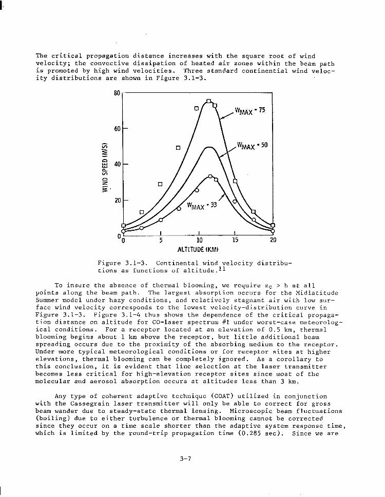
3.1 LASER BEAM SPREADING
Analytic calculations of laser beam propagation show that beam spreading due to atmospheric turbulence is negligible compared with spreading due to diffraction and pointing inaccuracies at the laser transmitter. Although the angular divergence attributed to turbulence is much larger than the divergence due to diffraction and pointing inaccuracy, the turbulence indiced spreading only occurs during the final 30 km of beam path, whereas the diffraction and pointing spreading occurs along the entire path (42,700 km). If laser line selection is employed, then molecular and aerosol absorption is weak and ther- mal blooming is not a problem. Note that for earth-to-space laser power trans- mission, however, small beam perturbations attributable to turbulence and non- linear effects near the transmitter produce significant beam wandering at the target because of the long optical "lever arm" involved. Due to the proximity of these effects to the receptor, beam spreading is much less severe for space- to-earth propagation.
In the sections which follow, beam spreading and required receptor size are calculated for two analytically tractable laser beam intensity distribu- tions which bound the range of expected profiles. These intensity distribu- tions are the uniform or constant-intensity profile and the Gaussian profile. Diffraction effects are considered initially, and the effects of pointing in- accuracies and turbulence are then calculated. Finally, thermal blooming is shown to be insignificant for worst-case propagation conditions. It is assumed that the receptor axis coincides with the laser beam axis such that the minimum focal spot size is intercepted. Hence, the receptor views the laser source at a zenith angle (8) of 50°.
3.1.1 UNIFORMLY ILLUMINATED TRANSMITTER APERTURE
If the primary mirror of the Cassegrain optical transmitter, an annular aperture, is uniformly illuminated by the laser, at the receptor due to diffraction only is69
then the normalized intensity
2
I(x) 2 = l2 2J1(") 2J+x) - f , (25) (1-c 1 2 X fX 1 where
x = (2a/~) (Dp/21 (r/R) I
and
3-l
(26)
J,(x) = first-order Bessel function of the first kind
E = transmitter obscuration ratio (D,/Dp)
DP = primary mirror diameter
r = radius at the receptor
R = range to the receptor.
For E < 0.1, Eq. (25) simplifies to
1 (xl = [2J,(x)/xl* .
The fractional power intercepted within a radius r0 is given by
x(ro)
F(ro) = 2 /
J;(X) dx ,
X
0
which can be analytically solved to yield
F(ro) = 1 - J~Ix(rg)l - Jf[x(r,)l.
(27)
(28)
(29)
3.1.2 GAUSSIAN INTENSITY DISTRIBUTION
The time-average intensity distribution at the receptor for a Gaussian- profile transmitted beam is 70
'TnT <I(r)> = - 2 exp(-r2/a2), ra
(30)
where PT is the transmitted optical power, '\T is the atmospheric transmission efficiency and a, the beam radius at the l/e-intensity points, is
(31)
8d, 0 turbu ence, P
) and et are the divergences due to diffraction, pointing jitter, and respectively, and R is the distance from the receptor for which
turbulence contributes to beam spread. The half-angle diffraction divergence is
2 2 8d = fi (2n)2ai
(1-$,', (32)
3-2
where the parameter B is used to characterize the beam quality of the optical transmitter in terms of its far-field or focused beam radius being a specified number (6) times the diffraction limited radius. The quantities a0 and f are the l/e beam radius at the transmitter and the optical system focal length, respectively. Setting f equal to infinity corresponds to a collimated beam, while setting f equal to R corresponds to best focus at the receptor. The latter condition applies here, so Eq. (32) reduces to
A ed= B- . 2na0 (33)
The divergence due to turbulence is
x et== I (34)
where 5, the turbulence coherence length, is given by Fried and Mevers 71 for propagation down through the atmosphere as
c = 0.114(Acose/5.5 x 10 -7]3/5 . (35)
The coherence length is related to the integral of the refractive index struc- ture constant, Ci, over the propagation path. The distance from the receptor for which turbulence effects cause beam spreading can be approximated by
ii = ht sece , (36)
where ht is the altitude where Ci experiences an abrupt fall-off in magnitude. FromFig. 3.1-1,ht = 20 km. Finally, the l/e beam radius at the transmitter is related to the primary mirror diameter, Dp, by the relation
D P =2J2ao ,
which places the l/e intensity points at the edge of the mirror.
In our case, we have D = 25 m, b = 1.0 [Reference (29)], 6 = 50°, E = 0.08, X = 5~10~~ m and #i= 4.27~10~ m; hence,
a0 a0 = 8.8388 m
5 = 0.3288 m
i = 3.111~10~ m
and the divergences are
8 d = 9.00x10-* rad
BP = 2.oox1o-7 rad [Reference (29)]
et = 4.84~10'~ rad.
3-3
ALTITUDE ABOVE SEALEVELIMETERSI
Figure 3.1-1. Ci as a function of altitude above sea level, h.ll
The l/e beam radius at the receptor is then
a (diffraction only) = 3.844 m
a (diffraction + pointing) = 12.384 m
a (diffraction + pointing + turbulence) = 12.385 m.
Clearly, turbulence-induced spreading is negligible compared with beam spread- ing caused by diffraction and pointing inaccuracies. Furthermore, if a smaller receptor spot size is required, then better pointing stability is necessary rather than a larger primary mirror since 8, > 8d.
At the receptor, the fractional power intercepted within a radius rC is
F(r,) = & /“d$f’<ItrI >dr , (38)
0 0
which can be simplified to
‘0
F(ro) = -$ /
exp(-r2/a2)r dr . a
(39)
0
3-4
Equation (39) is conveniently integrated using a Gaussian quadrature routine, 72
The percentage of available laser power intercepted by the receptor as a function of the receptor radius is shown in Figure 3.1-2 for several conditions. Considering diffraction spreading only, the two dashed curves show the functional behavior for the uniform or constant-intensity distribution and the Gaussian intensity distribution. These distributions bound the range of expected laser beam profiles, although the Gaussian profile more closely approximates the intensity distribution observed for practical laser devices. The solid curve shows the beam spread of a Gaussian beam including the effects of diffraction, pointing error, and turbulence, A 50-m-diameter receptor will intercept approx- imately 99 percent of the available power at the ground site. Improvement in the transmitter pointing accuracy could reduce the required receptor diameter to perhaps 30 m.
I I I I I I
/ Gaussian Beam Profile
/
Diffraction Only Diffraction, Pointing, and Turbulence
/
Uniform Beam Profile (Diffraction Only)
Cassegrain Transmitter
Dp= 25 m f =O.OB A =5pm R =42,700 km 8 =!xP p =I.0
I I
Receptor Radius, m 25 30
Figure 3.1-2. Percentage of available power at the ground based site which is intercepted within a specified receptor radius.
3-5
3.1.3 THERMAL BLOOMING
Thermal blooming is a nonlinear propagation mechanism common to high- power infrared lasers in which self-induced spreading, distortion, and bending of the laser beam occur as a result of molecular and aerosol absorption within the beam path. Absorption leads to heating of the air causing density and, hence, refractive index gradients which act as a distributed lens. In general, the explicit determination of the beam phase and intensity distributions at a target illuminated by a remote laser transmitter and separated by an inhomo- geneous absorbing medium requires numerical solution.73,74 For the purposes of the present study, however, we with only to determine the potential impact of thermal blooming on the present space-to-earth power transmission scenario.
There exists a critical distance, zc, beyond which beam distortion caused by blooming is substantial. For the case of no kinetic cooling of the absorb- ing medium (a good approximation for CO-laser light absorption), the expression for the critical propagation distance, in meters, is75
w 3
22 =
p (h)C v(h) (27~) (D /*)
C (-; $ 0.96 at(h)PT 8 t.40)
where p is the atmospheric density (g/m3>, constant pressure (0.242 Cal/g OK),
Cp is the specific heat of air at v is the wind velocity (m/set>, n-'(dn/dT>
is the refractive index gradient, and ot is the total molecular and aerosol absorption coefficient cm-'). Notice that p, v, and o.t are functions of altitude, h; hence, zc is implicitly a function of altitude. The refractive index gradient is also an implicit function of altitude because of the depend- ence of temperature on altitude. Now in Appendix A of Reference (ll), it was shown that
at(h)
Cpp (h) n-l at(h)
= - - pocp T(h) 8 (41)
where p0 is the sea level density of air in the U.S. standard atmosphere (1.225x10³g/m3), and
(n-l) x lo6 = 272.729 + (1.42823/h2) + (0.02041/h4>.
For X = 5 urn, n-l = 2.73~10~~. Inserting these numerical values and Eq. (41) into Eq. (401, we obtain
z2 3.544 x 10' v(h)D3T(h)
= I C at(h)PT
(42)
3-6
The critical propagation distance increases with the square root of wind velocity; the convective dissipation of heated air zones within the beam path is promoted by high wind velocities. Three standard continential wind veloc- ity distributions are shown in Figure 3.1-3.
ALTITUDE (KM)
Figure 3.1-3. Continental wind velocity distribu- tions as functions of altitude.ll
To insure the absence of thermal blooming, we require zc > h at all points along the beam path. The largest absorption occurs for the Midlatitude Summer model under hazy conditions, and relatively stagnant air with low sur- face wind velocity corresponds to the lowest velocity-distribution curve in Figure 3.1-3. Figure 3.1-4 thus shows the dependence of the critical propaga- tion distance on altitude for CO-laser spectrum #l under worst-case meteorolog- ical conditions. For a receptor located at an elevation of 0.5 km, thermal blooming begins about 1 km above the receptor, but little additional beam spreading occurs due to the proximity of the absorbing medium to the receptor. Under more typical meteorological conditions or for receptor sites at higher elevations, thermal blooming can be completely ignored. As a corollary to this conclusion, it is evident that line selection at the laser transmitter becomes less critical for high-elevation receptor sites since most of the molecular and aerosol absorption occurs at altitudes less than 3 km.
Any type of coherent adaptive technique (COAT) utilized in conjunction with the Cassegrain laser transmitter will only be able to correct for gross beam wander due to steady-state thermal lensing. Microscopic beam fluctuations (boiling) due to either turbulence or thermal blooming cannot be corrected since they occur on a time scale shorter than the adaptive system response time, which is limited by the round-trip propagation time (0.285 set). Since we are
3-7
I II
0.5 I IO IO too
Altitude (h), km Altitude (h), km
Figure 3.1-4. Critical propagation distance for thermal blooming as a function of altitude.
interested in power rather than information or image transmission, this should pose no problem,
3.2 SAFETY AND SECURITY
The transmission air zone associated with all receptor sites must be restricted to all private, commercial, and military aircraft.of all types. High-speed jet aircraft probably will not suffer any damage in traversing the beam, with the possible exception of the canopy. The dwell time within the beam and the high infrared reflectivity of aluminum skins combine to yield absorbed fluence levels (J/cm*) far below those required for damage. Slower, less reflective aircraft could succumb to damage. The principal reason for restricting all air traffic is the occular hazard presented by an uncontrolled and randomly pointing reflection surface traversing a 100~MW laser beam. Co- herent optical adaptive techniques (COAT) have been suggested as a viable solution to sense intruding aircraft and affect beam defocus. The system
3-8
response time is limited by the round-trip light propagation time, 0.285 set in this case. In this time, most high-speed jet aircraft would have completely passed through the beam, and to defocus would be useless. Introducing aircraft should be detected by radar as they enter the restricted zone to allow suffici- ent time for defocus.
Sensing the unintentional loss of pointing accuracy would also be limited by the system response time. The ground distance slewed by the beam in travel- ing away from the receptor site before complete laser shut-down is a function of the maximum plausible rate of angular beam deflection. Due to the immense size of the proposed SPS, angular beam deflection caused by gross platform motion will occur on a time scale much slower than the laser system response time. The most plausible accident corresponds to complete loss of laser- transmitter phase control.. The highly improbable; but worst-case situation, thus involves a slew in the optical pointing vector by about 1.6~10~~ rad, representing a maximum shift in the primary mirror phase of 4 wavelengths be- fore laser shut-down. Under these circumstances, all or part of the beam will slew away from the receptor by about 70 m before power-off conditions are achieved. Hence, large slew distances of the focused beam are not possible.
Because of the laser's damage potential to biological entities,76 it is imperative that adequate safeguards and security exist to prevent sabotage or hostile control. These safeguards would normally take the form of failsafe criteria and automated power-up/power-down sequences, although the satellite could conceivably defend itself against hostile forces in space.
A small percentage of laser power spillover (51%) will be unavoidable at the receptor device. Hazards to operating personnel and innocent bystanders exist due to possible specular or diffuse reflections from the spillover region adjacent to the receptor device. Operating personnel will be required to wear protective goggles and clothing when working in this region. An opaque peri- meter fence, of appropriate height, will be placed at the boundary where the time-average power density equals the maximum recommended continuous exposure levels for humans. The American National Standards Institute (ANSI) exposure limit for cw infrared lasers is 100 mW/cm'. This limit was determined for relatively small spot sizes on the skin or eye based on durations in excess of 10 sec. For large-area, long-duration exposure, Sliney et a1.77 recommend an average ocular or wholebody irradiance limited to about 10 mW/cm*.
The protection radius as a function of perimeter power density is shown in Figure 3.2-l for the uniform-intensity and Gaussian laser beam distributions. If a maximum permissible exposure limit of 10 mW/cm' is adopted and if allow- ance for the maximum plausible accident is included, a protection radius of 300 to 800 m is appropriate. Note that because the propagation axis is not perpendicular to the earth's surface, an elongated "footprint" will be produced at the receptor site. This effect has been included in these results.
The total land areas required by the receptor site is estimated to be 0.3 to 2 km*. Security systems will be necessary at the receptor site to ensure public safety, although security problems will be more manageable due to the small land area involved. Note that if multiple receptor devices are located in close proximity at a common location, the required perimeter radius
3-9
IO4 I I III I IllI I I I II I -r Ii
Uniform Beam Profile
(Proticol Beam Profile + Slewing Safety Morgin 1
Goussion Beam Profile
Moximum Permissible Exposure Level
IO’ I I II I IIll I 1 Ill J
IO-’ lo-2 16’ IO0 IO’ Perimeter Power Density, W/cm’
Figure 3.2-l. Receptor site protection radius as a function of the perimeter power-density level.
and land area will increase slowly with the number of devices and not in an additive fashion.
3.3 LASER SPS MASS AND VOLUME ESTIMATES
Specific mass estimates for each subsystem are given in Table 3.3-l along with the source of information. These data were used in conjunction with the power distribution data given in Table 2.5-l to calculate the laser subsystem and total system masses and the mass per unit of radiated laser power. These results are given in Table 3.3-2. Monson2 estimated that this latter parameter, the total system specific mass, is lowest for the CO EDL, followed in increasing magnitude by the CO2 EDL, a direct solar pumped laser (nL = 0.101, and finally by the CO2 GDL. Only a direct solar pumped laser having an overall efficiency nL > 0.20 is capable of improving the total system specifiec mass. No satis- factory scheme for producing such a laser has yet evolved.
Volume estimates indicate that the multiple-laser-transmitter approach appears viable as a replacement for the microwave transmitters on Rockwell's current SPS system design. Available space-radiator area within the yoke is approximately 1.92 km* (one side), whereas the required space radiator area is 1.58 km*. Ample area exists on the opposite side for heat-load management during periods when one radiator surface faces the sun.
3-10
Table 3.3-l. Assumed subsystem specific masses for candidate closed-cycle lasers.
Subsystem Description Specific Mass Ref.
Power Sources:
laser discharge supply power 2.0 kg/kWe 78 compressor motor and power converter 2.5 kg/kWe 79
Compressor 0.1 kg/kW, 80
Waste Heat Exchanger 0.2 kg/kWth 81
Laser Fluid, Ducting, Channel, and Optics 0.7 kg/kW, 81
Space Waste-heat Radiator 2.0 kg/m2 81
Transmitting Optics:
primary mirror
secondary mirror
40 kg/m2
350 kg/m2
29
82
Table 3.3-Z. Subsystem and total system mass estimates.
Subsystem Description Mass (10 3 kg)/Laser System 20 Lasers 24 Lasers
Power Sources:
laser discharge power supply compressor motor and power
The technology issues which will require considerable research and development in order to realize the performance goals desired for a laser based SPS include the following:
. Scalability by a'factor of 1000 in output power beyond that of experimental devices,
. Method of cooling of a large-area transmissive laser window having an incident power x100 MW,
. Method of gas purification/rejuvenation in a closed- cycle system.
Since these issues may present real impediments to the realization of a laser based SPS, it is imperative that they be resolved before proceeding with any detailed conceptual design.
The technical issue deserving perhaps the greatest attention is the method of coupling the laser flux within the excitation region to the transmitting optics. Two window types are available, viz., aerodynamic and transmissive. Aerodynamic windows have been built for supersonic-flow CO EDL's,~~ and specially designed configurations 84 have been developed in an effort to mini- mize the required mass flow rate and mass loss, which scale with the window aperture diameter. To this author's knowledge, however, the design or evalua- tion of aerodynamic windows for supersonic-flow CO lasers operating in space has not been performed. Therefore, their suitability for use in the present application remains in question. A key issue is the mass loss rate, since large quantities of onboard consumables are highly undesirable.
Regardless of whether the output beam is converging, diverging, or quasi- parallel, any transmissive window will absorb sufficiently to produce a severe volumetric heat loading. Ai;hg;gh great advances have been made in the areas of solid-state ir materials ' and coatings,87 a satisfactory cooling method applicable to large-area transmissive optics subject to power densities ~3 kW/ cm2 has not been devised.88 Large temperature gradients in laser output couplers employing transmissive optics usually lead to window failure due to thermal-stress fracture.89 This issue will strongly influence any reliability estimates. It should be noted, however, that single or multiple subsystem failures in one laser transmitting chain will not impede the ability of unaffected chains to function.
3-12
4.0 ENVIRONMENTAL IMPACT ASSESSMENT
4.1 HEATING OF THE ATMOSPHERE
4.1.1 SOURCES OF WASTE HEAT
Waste thermal power from the laser-SPS will be available to the atmosphere as either sensible or latent heat. Sensible heating of the atmosphere will occur as the result of laser-beam propagation inefficiencies, i.e., aerosol and molecu- lar absorption. As shown by the deposition profiles in Figures 4.1-l and 4.1-2, most of the direct heating of the atmosphere occurs in close proximity to the receptor due to absorption processes in the lowest atmospheric layers. Mountain- top receptor operation largely mitigates any direct, sensible-heat input to the troposphere. Latent heating of the atmosphere, on the other hand, will occur as the result of waste heat generated by the receptor device and associated electri- cal power plant. The magnitude of this thermal source depends on the power rating of the plant and its thermodynamic or laser energy conversion efficiency. Before considering the ramifications of the distributed sensible heat source to local meteorology and the effects of the latent heat source upon the regional ecosystem, we examine the possibility for global climatic change due to laser- SPS proliferation.
4.1.2 POSSIBILITY FOR GLOBAL CLIMATIC CHANGE
"Waste" heat is an inevitable consequence of.the utilization of most energy sources, and it dissipates in the atmosphere, surface layers of the earth, and surface waters. An estimate of the level at which waste-heat dis- posal at or near the earth's surface might induce global climatic alteration is not difficult to perform. The average rate of absorption of solar energy is about 250 W/m2, and simple climatic models suggest that thermal polution sources which increase this malue by about one percent may produce serious consequences. go,91 Based on the present laser-SPS design, it would require a proliferation of 200,000 to 400,000 complete satellites to.'induce this magni- tude of waste heat. The quoted range accounts for the possible range in various system powers and efficiencies. To quote Reference 90:
Most of the inadvertent climate changes which man might cause represent variations that are comparable to the noise level of the natural variability of the atmosphere, as well as being within the uncertainty range of current modeling techniques.
4.1.3 METEOROLOGICAL IMPLICATIONS
Direct laser-beam heating of the troposphere, is likely to induce local meteorological changes. The effects of heat input from a distributed source (see Figures 4.1-l and 4.1-2) will differ from effects typically found near fossil-fuel electric power plants.
Figure 4.1-1. Fraction of transmitted laser power absorbed or scattered by each atmospheric layer (Midlatitude Summer Model).
Molecular Absorption Onl
Cteor(23-km visibility)
HazyIS-km visibility)
‘” 0.5 3.5 6.5 9.5 14.5 24.5 Layer Altitude, km
Figure 4.1-2. Fraction of transmitted laser power absorbed or scattered by each atmospheric layer (Midlatitude Winter Model).
The nature of the distributed source suggests that significant updrafts will exist in the lower troposphere above the receptor site. Because of pre- vailing winds and the Coriolis effect, the ensuing convective air movement may assume a helical or vortex flow. The turbulence associated with this effect will probably be severe in the lower troposphere, another reason for designat- ing the air.zone above the receptor location restricted. It is interesting to compare this "vortex" flow with other naturally occurring phenome;?. For example, the kinetic energy associated with a tornado is -100 MW. While the estimated kinetic energy associated with laser-heating of the atmosphere is about two orders of magnitude smaller, the effect is certainly not insignifi- cant. There is one outstanding positive benefit to this effect-the strong convective updraft will promote verticle mixing and waste-heat dispersal more effectively than man-made edifices such as cooling towers. Unlike many cooling towers, which rely upon evaporative cooling, atmospheric disposal of that por- tion of the plant's waste heat due.to laser-beam absorption will not induce cloud generation.
The'multi-megawatt laser beam will, however, and light cloud covers.41
bore holes in ground fogs By heating the aerosol droplets, water evaporates
leaving the condensation nuclei behind. densities of the order of several kW/cm'
Reference 41 estimates that power would be necessary to bore through
moisture-laden cloud covers; hence, during periods of precipitation or heavy cloud covers, power generation at the affected receptor would terminate and that particular laser beam should be shut off or redirected to an alternate receptor. The power density threshold for boring, Ib (W/cm'>, is41
I b 2% (1 + O.l$L),
where v is the wind velocity (m/set), the moisture content (g/m3),
D is the laser beam diameter (m), Q is and L is the cloud or fog thickness (m). In
addition to moisture content, increasing wind velocity will also increase the threshold for penetration. The environmental impact of laser hole boring in tropospheric clouds and fogs is believed to be negligible since they will recondense after passing through the beam path. Noctilucent clouds, nucleated ice crystals high in the mesosphere, will be vaporized by a 100-MW laser beam. These formations are so rare in time and space that the environmental conse- quence of their vaporization is deemed insignificant. Furthermore, since most cloud types in the troposphere and stratosphere will renucleate after passing through the beam, the prospect for changing the continental cloud distribution or albedo is highly improbable.
4.1.4 AEROSOL EFFECTS
Aerosols are produced by direct injection from terrestrial sources or by in situ homogeneous or heterogenous particulate formation. Destruction mech- anisms include rainout, washout, and sedimentation. Natural sources for continental aerosols include dust storms (particles > 0.6 pm in diameter), photochemical gas reactions involving ozone and hydrocarbons (CO.4 pm) and various trace gases with ozone and atomic oxygen (various sizes), and volcanic injection of SO2 which reacts with 0 and Hz0 to form heterogeneous surface particles (-0.5 urn diameter average). Man-made sources include combustion,
4-3
both carbon or soot particles and partially or unburned hydrocarbons which react with NOx to form smog (CO.4 pm), and SO2 from industrial polution which also reacts to form sulfate particles.
The concentration of small particles (Aitken nuclei, CO.2 urn diameter) decreases with increasing altitude, consistent with their terrestrial origin. The concentration of large particles (0.2 - 2 pm.diameter), however, shows a maximum at about 18 km (the Junge sulfate layer). The formation mechanism involves oxidation of SO2 to SOS,~~ reaction of the SO3 with water to form H2S04,g4 and clustering of H~SOI+ and Hz0 molecules to form prenucleation embryos followed by heteromolecular nucleation. g5 A small concentration of hydrated (NHI+)~SOL, has been found in stratospheric aerosols, as well as traces of numerous other compounds. The residence times for aerosols in the lower stratosphere (1-3 years) and upper stratosphere (3-5 years) are appreciably longer than the lifetime of tropospheric aerosols (6 days - 2 weeks). Exceed- ingly long residence times (5-10 years) are experienced by the low concentra- tions of aerosols in the mesosphere.
As shown in Figures 4.1-1 and 4.1-2, aerosols are the primary absorbers in the stratosphere (aerosol absorption and scattering coefficients are about equal at X = 5 urn). Because the Junge layer is important to the heat balance in the lower stratosphere and because of the long residence time of strato- spheric aerosols,g6-g8 the possibility of laser-induced depletion of this layer must be considered. Two processes for decomposition of sulfate aerosols by laser irradiation are possible for laser power densities -10 W/cm2. First, absorption of ir radiation is known to preferentially excite certain vibrational modes in polyatomic molecules. Dehydration of cluster molecules is a probable reaction because of the low bond energy of H20 to the cluster, i.e.,
H2S04 l (HzO)~ -f H2SC4 l (H20),-1 + H20,
followed by V-T collisional relaxation of the reaction products. Second, rapid heating of an aerosol particle exposed to intense ir i$ser radiation causes internal pressures sufficient for explosive break-up. Since the fundamental constituents of the aerosols remain after passing through the beam, then re- nucleation will probably occur and depletion of the Junge layer is not believed possible. The irradiated layer volume will be insignificant compared with the whole, and anthropogenic increases in the total mass of sulfate particles will completely outweigh any depletion rate associated with laser-SPS proliferation.
4.1.5 RECEPTOR THERMAL POLUTION
From the geophysical perspective, the exact method of waste heat disposal from the receptor power plant is probably not very important, but persistent local weather and biological effects can be quite different for dry cooling towers, wet towers, or cooling to bodies of water. Poorly sited wet cooling towers can produce unpleasant local modification of fog and drizzle frequencies. Cumulus cloud formation induced by wet cooling towers is fairly common. Increasing the ambient temperature of rivers or estuaries by their use as a source of cooling water for electric power plants is known to alter the local
4-4
biological ecosystem. The environmental impact of thermal polution from receptors and conventional or nuclear power plants is qualitatively similar and will not be discussed further here.
4.2 ENVIRONMENTAL IMPACT ON WILDLIFE
In addition to providing protection to the general public, the perimeter "fence" will protect most indigenous animals from exposure to dangerous irrad- iance levels; the principal exception is birds. In traversing the primary beam, birds and insects will certainly be incinerated. There is some contro- versy over the ability of birds to sense the dangerous irradiance levels and to avoid the beam. It is difficult to resolve this point without experimental studies, and studies involving high-power radar transmitters are not applicable to the present problem. It is doubtful that infrared-heat-sensitive insects would be attracted to the laser beam because of the extremely small intensity of side-scattered light. Again, definitive experimental verification is lacking.
4.3 LASER-PLASMA INTERACTIONS IN THE IONOSPHERE
4.3.1 IONOSPHERIC PARAMETERS
The properties of the ionosphere, especially the electron density profile, are variable to a great extent with latitude, local time (diurnal variation), season, and solar activity. The ionosphere extends from about 40 km above the ground to an altitude at which H + becomes the main ion constituent (-1000 km). The division of the ionosphere into several regions, C, D, E, and F, are made for conventional, and not necessarily physically compelling reasons.
The C region (-40-60 km) is produced primarily by cosmic rays, and its peak electron density is -102 electrons/cm3. The D region (-60-85 km) is formed primarily because of photo-ionization produced by Lyman-alpha (121.6 nm) solar radiation. The steep increase in the electron density in the lower part of the E region (-85-140 km) is due to photo-ionization by soft X-rays. The Fl (-140-200 km) and F2 (-200-400 km) regions are produced by photo-ionization by extreme-ultraviolet (euv) solar radiation, principally in the wavelength range 30 nm to 80 nm.
Electron density profiles for the ionosphere at midlatitudes are shown in Figure 4.3-l. The D-layer disappears at night and there is virtually no ioniza- tion present below about 80 km. The Fl- and F2-layers coalesce in the absence of sunlight. Occasionally, "clouds" of ionization, called sporadic E, are observed at low E-layer altitudes. Ionospheric parameters used in the analyses which follow are given in Table 4.3-l.
4.3.2 LINEAR AND NONLINEAR DISSIPATIVE HEATING
In general, electromagnetic radiation propagating through a cold, aniso- tropic plasma will lose energy due to linear (ohmic) and nonlinear (anomalous) absorption. For an intense ir laser beam propagating through the ionosphere, the possibility for perturbing the electron concentration, ne (ms3), or the
4-5
0 I 1 I 1 102 iO2 10’ 10’ 10’ 10’ 10’ 10’ 1oC lot 10’ 10’
Electron concentrarion Wcu0ndcm’) Electron concentrarion Wcu0ndcm’)
Figure 4.3-l. The concentration of electrons in the earth's ionosphere for representative conditions.100
Table 4.3-l. Ionospheric parameters. 101,102 When two numbers are entered, the first refers to the lower and the second to the upper portion of the layer.
I -____
Quantity
lectron density, n,(m -3 1
Ion-neutral collision frequency, vi(sec-l)
Ion-cyclotron frequency, wi(rad/sec)
Electron-neutral collision frequency, ve(scc-l)
Electron-cyclotron frequency, ~~(rad/sec)
/de;; molecular weight,
II___- ___-- ___- E Region
loll - 2 x lOI1
2 x lo3 - lo2
180 - 190
1.5 x lo4 - 9.0 x lo4
6.2 x lo6
28 - 26
F Region -- ._
2 x loll - 2 x 1o12
0.5 - 0.05
230 - 250
80 - 10
6.2 x lo6
22 - 20
4-6
electron and ion temperatures, T, and Ti (eV), is examined in an effort to determine the potential environmental impact on the upper atmosphere.
Conservation of energy relates the divergence of the Poynting vector z to the net dissipation rate within the plasma:
v ’ Z-Q= - (Q, + Q,,,,) .
The dissipation rate Q (W/m3) is composed of homic loss QL (linear joule heat- ing) and anomalous loss Qanom due to collisional and Landau damping of plasma waves. The latter quantity is important only when one or more thresholds for excitation of the various plasma instabilities is exceeded. Poynting's vector . is related to the electric- and magnetic-field vectors by
5=2xL (45)
The time-average flux of energy is given by the real part of the complex Poynting vector:
(46)
where * denotes complex conjugate. The laser power density (W/cm2) is the magnitude of Poynting's vector. The magnitude of the peak electric-field strength, Eo (V/m), and the laser power density are related by (free-space approximation)
S = av ( ;,, ( = + CEDE;
= 1.327 x 1O-3 E; (47)
The linear dissipation term, QL, is given by the equation
QL=+?, (48)
where J(A/m ) is the current density. For a magnetized plasma,
s = ““t,, + ul$ + 02&i x 2)) (49)
where 3 (Weberjm:) i$ the earth's mzgzetic induction, 2 (V/m> is the laser's zlectris fi$ld,+B = B/ IB[ , El1 = (E*B)g is the electric $ield parallel to B, and El= E - El1 is the electric field perpendicular to B. The conductivity elements ~0, 01, and ~2 are called the direct (or longitudinal), Pedersen, and Hall conductivities, respectively. In general, each is of the form
U = OR + io* , (50)
where the real component accounts for attenuation of the EM wave and the imaginary component is responsible for a phase shift. Without showing all the
4-7
tedious algebraic details, the real parts obtained from the standard expressions as
.Y L nee V
Re u0 = - m e
2 2 nee VW ee Re o1 = -- m 4 e I.0
2 nee cd Re a2 = - e
m 7 e
of the three conductivities can be follows:
(51)
(52)
(53)
where ne is the electron density (electrons/m"), (1.602x10⁻¹gcoul),
e is the electronic charge me is the electron mass (9.1095x10S3'kg), we = eB/m, is
the electron cyclotron frequency (rad/sec), and V, is the electron-neutral collision frequency (set-l). These as well as other cogent parameters are listed in Table 4.3-l. In deriving Equations (51) through (53), it is assumed that ve << we << w, while the ions are infinitely massive and only the elec- trons contribute to the conductivity.
The laser light angular frequency is given by
w = 2ric/A = 1.885 x 10¹⁵/X , (54)
where A is expressed in urn. For A = 5 urn, w = 3.77 X 10¹⁴ rad/sec and the aforementioned assumptions are well satisfied. Using the data in Table 4.3-1, the conductivities are
Re o. = 3.Ox1O-22 - 4.0x10⁻²⁴mho/m
Re 01 = 8.0x10-36 - 1.1x10⁻³gmho/m
Re o2 = l.2X1O-1g - 2.5x10⁻¹⁸mho/m
where the range is taken from the lower E region to the F2 region with maximum "e- Now we do not know the relative orientations of E and B a priori, since the propagation path through the geomagnetic field and the laser polarization state are unspecified. Clearly, the maximum ohmic loss occurs when E is per- pendicular to B. Equations (48) and (49) are then combined to give
Q, = i (Reu2)Ei (55)
where secondary terms are ignored since Re ~1 << Re UO << Re ~2. For a 100-MW, 5-pm laser beam incident upon the ionosphere at an unspecified angle, the maximum dissipation rate is
4-8
Q, = 0.008 - 0.17 nW/m',
which occurs about local noon during periods of maximum sunspot activity. The range quoted above is for altitudes of 120 km to 340 km, corresponding to the lower E-region during periods of minimum solar activity and to the upper F2- region during periods of maximum solar activity, respectively.
It is informative to compare QL with other naturally occurring dissipa- tion rates.l03,104 Ab ove an altitude of about 80 km, the primary dissipative mechanism of the solar flux is 02 absorption in the Schumann-Runge continuum (125-175 nm), which is the principal source of oxygen atoms in the upper atmos- phere. Extreme ultraviolet (euv) radiation (cl00 nm) from the sun photoionizes the atomic oxygen and above 160 km, O+ is the dominant positive ion. Using data obtained from Figure 4.3-2, the solar-flux dissipation rate due to molecu- lar oxygen absorption, QSR, can be computed as
Q SR = 970 - 0.26 nW/m3,
where the range applies to altitudes of 120 km to 340 km, respectively. Hence, for most of the ionosphere, the energy dissipation rates of naturally occurring phenomena far exceed the maximum estimated dissipation rate which may be intro- duced by ohmic heating. lo44
Figure 4.3-2. Altitude dependence of energy absorption and emission (Ref. 105).
MANN RuNGE
- DEPOSITION
-..-. COOLING
lo-“1 ’ ’ ’ ’ ’ ’ ’ ’ ’ ’ ’ 60 100 200
ALTITUDE (km)
4-9
In the last decade, the subject of radiation induced parametric instabil- ities has received intensive study. These instabilities have been observed in experiments involving rf heating of the ionosphere by powerful ground-based microwave transmitters and in magnetically confined plasma experiments for thermonuclear fusion research. More recently, the parametric excitation of plasma instabilities by intense coherent light has become an exceedingly active field of research, spurred by interest in laser-induced thermonuclear fusion.
These instabilities can lead to anomalous absorption or stimulated back- scatter of the incident radiation. Each type of instability is associated with a certain density regime within the plasma and has a characteristic power density (W/cm ) threshold for excitation which depends on a number of plasma parameters (see, for example, References 106-110). An important characteristic of the plasma is the electron plasma frequency, given by
= 56.4 n1'2 , e (56)
where the units of ne are m-'. According to linear plasma theory, EM radiation having an angular frequency w 5 mpe will be reflected from the "critical density" layer Upe(nE) = W.
A variety of nonlinear processes are known to exist, including the para- metric decay and oscillating two-stream instabilities (both important when fJJ N upe), resonant absorption (w = wpe), and stimulated Raman (w = 2 opt) and Brillouin (any w > c+,~> scattering. The instabilities may be conveniently thought of as the induced decay of an incident photon into various elementary excitations. Thus, the parametric decay instability corresponds to the decay of a photon into a plasmon and phonon. Further possibilities are photon-tplasmon + plasmon, or + plasmon + photon' (SRS), or + photon' + phonon (SBS). Using the peak electron density observed for the F2-region and Equation (56),
w = 8x10' rad/sec. pe
For a 5-urn laser, w = 3.8x10'4rad/sec and, hence
w >> w pe
and the laser beam will not be reflected at any electron-density layer. Further- more, the only instability which can be excited in a greatly underdense plasma ("e << n:) is stimulated Brillouin scattering, which has a power density threshold (-1010W/cm2) far greater than the proposed power density incident upon the ionosphere (-18 W/cm*). Therefore; we conclude that
Q = 0. anom
4-10
For microwave interaction with the ionosphere, w 2 %e and anomalous absorption resulting from parametric instabilities are no longer insignificant. In F-layer heating experiments, increased electron temperature and enhanced airglow were produced at irradiation power densities -10 VW/m* by ground-based rf transmitters operating at frequencies in the range of a few to 10 MHz (see, for example, References 111-114). In the upper ionosphere, dissipative heat- ing pr0duces.a spatial redistribution of electrons which is manifested by a depletion in electron density. Field aligned density irregularities give rise to various tattering phenomena (e.g., spread-F). In the D-region, the increased electron temperature lowers the electron-ion recombination rate, resulting in an increase in electron density. Plasma instabilities also modify the electron energy distribution. The enhanced high-energy tail of the distri- bution can promote the excitation of various atomic species and a concomitant increase in airglow.
4.3.3 INVERSE BREMSSTRAHLUNG ABSORPTION
Another method of examining the effect of the laser beam is to calculate the fraction of power absorbed via electron-neutral and electron-ion brems- strahlung, Pa, given by
m
'a = PT[l - exp(- k(h)dh) I,
where the absorption coefficient as a function of height is 115
where k is in units of cm-', the laser wavelength X in urn, the electron density n, in cms3, and the electron temperature T, in eV. The non-hydrogenic correc- tion factor 5 = c(X,n,,T,), which is close to unity, is plotted in Reference 116. Using the electron density profile shown in Figure 4.3-l for maximum sunspot activity, the ionospheric absorption fraction is estimated to be
Pa/PT <, lo-'5,
and thus, is insignificant.
4.4 PERTURBATION OF THE PLASMA CHEMISTRY OF THE MESOSPHERE AND THERMOSPHERE
Preliminary examination has revealed that certain reactions in the meso- sphere and thermosphere may be induced by the presence of an intense ir-photon flux and chemical reaction channels may be altered. In the upper atmosphere, mid-ir photons have sufficient energy only for vibrational-state photoexcita- tion and a limited num-er of charged-species reactions, such as positive- and negative-ion photodissociation and electron photodetachment. Such laser photons have insufficient energy for any photoionization or neutral photo- dissociation reactions of interest to upper-atmosphere constituents. Multi- photon processes are only important when the collisional or radiative relaxation rate is much longer than the photoexcitation rate.
4-11
The environmental consequences of plasma-chemistry perturbations are uncertain. Any mechanism which alters the electron density or the relevant temperatures of the various species (T,, Ti, T,)will have some environmental ramifications. The manifestations of these phenomena, such as enhanced air- glow and changes in hf communications, are not fully understood. Probably the worst consequence of any space-to-earth power beaming scheme would be depletion of the ozone layer which protects the earth's surface from harmful uv radiation. Most of the .ozone is found below an altitude of 50 km. Some depletion above that altitude would have little consequence; however, ozone does not absorb in the mid-ir wavelengths and no direct photodestruction scheme at any altitude was identified in this study. Secondary reaction chan- nels (discussed below) may alter the 03 concentration, but only at high alti- tudes (>60 km) and only in a localized manner.
4.4.1 VIBRATIONAL PHOTOEXCITATION
Molecules can be vibrationally excited by a variety of mechanisms, includ- ing exothermic chemical reactions, electron impact, V-V energy transfer, and photoexcitation. Sunshine and earthshine are the primary radiation sources for photoexcitation of upper-atmosphere molecules under undisturbed conditions. The earthshine appears to be the most important source of vibrational excita- tion for wavelengths 2 5 prn.l17
Among the molecular species of the upper atmosphere, the metal oxides are most susceptible to this source of excitation, since their band fundamentals tend to fall near the peak of the earthshine irradiance spectrum and collisional quenching of their vibrational states is s10w.l~~ Because the CO laser spectrum consists of a number of discrete lines, absorption transitions would need to be coincident with the laser lines for significant photoexcitation to occur. While the detailed transition levels of the various metal oxides have not been examined in detail, the concentrations of metal oxides are so low and the laser-beam area is so small that the likelihood of serious ionospheric pertur- bation is insignificant. Furthermore, almost all of the metal oxides, such as AlO, FeO, etc., reradiate in the infrared and, hence, no visible airglow would be observed.
4.4.2 CHARGED-SPECIES REACTIONS
Most of the charged-species reactions of interest to the present discus- sion are possible only in the D-region. The D-region is the most chemically complex region of the ionosphere. The flux of energetic particles and photons is insufficient to maintain a highly ionized plasma at the ambient pressure. Hence, the D-region consists of a large concentration of neutral species in which positive and negative ions are the principal charge carriers and complex ion-interchange and electron attachment and detachment reactions occur. Spe- cies of importance to D-region chemistry are listed in Table 4.4-l. Schematic representations of the positive- and negative-ion reaction channels are shown in Figures 4.4-l and 4.4-2. Because solar euv radiation is the primary ioniza- tion source, the ionic concentrations show a diurnal time dependence, as shown in Figures 4.4-3 and 4.4-4.
4-12
I
Table 4.4-l. Species of importance to the sub-D- and D-regions.
NClJtrOl,
CH4
co
co2
H
HN02
HN03
HO
H02
H 2
H2°
H202
N
NO
N02
No3
N2
N20
N205
0
02
O3
Neutral
Excited States
N(‘D)
N2& j
Oh
Oh)
02b’Ag)
02(b ‘r ;)
Negatives
co;
CO,(H,O)
co;
CO;W,O)
NO;
NO;(H20)
NO; *
N”;(Hp)n~,~5
0-
O2
O;(H20)
O3
0;
OONO-
4-13
Poritiver
H+;W20Jn=, es
H+(H20)(HO)
H+W20)(N2)
N+
NO+
NO+(C02)
NO+W20),,.,-3
NO+{ N2’
NO;
+ N2
0+
+ O2
O;(H20)
0:
~ - . . - _...---
m OBSERVED /-z&T--
Figure 4.4-l. Schematic representation of the formation of positive ions in the D-region.121 The dashed lines indicate possibel reactions.
TE: THE DIFFERENCE OETWEFN THE DESIGNATIONS OONO- AND NO; IS EXPLAINED ON PAGE 10A-7.
Figure 4.4-2. Schematic representation of the formation of negative ions in the D-region.121 The solid lines indicate probable reactions, on the basis of experimental measurements of the rate coefficients.
4-14
‘l----’
‘0 IO 20 30 40 50 60 70 60 IO-’ X TIME. m
Figure 4.4-3. Calculated positive-ion concentrations in the D-layer at 70 km for a day in which the noonday sun is overhead: -, ordinary day; ---, total eclipse of Nov. 12, 1966. (Ref. 122)
‘Or-----l
IO-’ x TIME, s.c
Figure 4.4-4. Calculated negative-ion concentrations in the D-layer at 70 km for an ordinary day in which the noon- day sun is overhead.l22
-.
Photoreactions in the D-region which may be induced by single or multi- photon processes involving an intense photon flux from an infrared laser are listed in Table 4.4-2. The CO laser photons have an average energy of about 0.25 eV; hence, most of these reactions are inaccessible by single-photon processes. If the ionic species possess a long V-T relaxation time, however, then photodissociation or electron photodetachment is possible by multiphoton excitation. Again, because the interaction volume is so restricted, signifi- cant modification to an appreciable fraction of the D-layer is not believed possible. This premise should be verified by kinetic modeling which accounts for all plausible processes. Perturbations of this region are known to greatly affect the absorption of hf radio signals and the reflection of If signals. For this reason, the remote possibility of D-region modification by space-to- earth laser power transmission should be investigated further.
Table 4.4-2. Photoreactions involving charged species found in the D-region which may be induced by an intense ir-photon flux.
~-- Photodetachment Threshold or
Reaction Dissociation Energy, eV
Negative-ion electron photodetachment and photodissociation:
0; t hv + e- + 01 0.46
O;(H,O), + hu + O;(HZO),-~ t HzO, n = l-5 0.8 - 0.5
0; t hv -t 0; t On 0.54
co7 + hv + 0; t CO> 0.8
Positive-ion photodissociation:
H~O+(HZO!~ + hu + H,O+(ll~0)~-1 + 1120, n = l-5 - - -
NO+(HzO& + hv + NO+(HZO)~-~ + HnO, " = 1-3 - - -
In the E- and F-regions, the only energetically accessible reaction which was identified is
0: + hv(lO.32 eV) + 0; + 0 .
The concentration of O+ T ,s so low that the consequences of increasing its photodissociation rate (which is already large because of the solar flux) by laser-power beaming are completely negligible. Furthermore, only shorter- wavelength laser photons have sufficient energy to induce this reaction.
4.5 ALTERNATE POWER-BEAMING LASER WAVELENGTHS
The "best" wavelength regime represents several tradeoffs between atmos- pheric transmission efficiency and potential environmental risks. Based on minimization of molecular absorption and aerosol extinction, several high- transparency windows in the approximate wavelength range of 3.6 to 3.8 pm can be found. Several regions of low molecular absorption exist at shorter wavelengths, but aerosol attenuation is more of a problem (refer to Figure 2.3-l). Furthermore, operation at shorier wavelengths (and larger photon
4-16
energies) makes an increasing number of plasma reactions energetically access- ible, which may have portentous environmental ramifications.
Longer wavelength "windows" are present, e.g., at the 9.114-ym line of isotopic COz. The molecular absorption which does occur, however, is distrib- uted such that sensible heating will occur at high altitudes. This is believed to be undesirable from an environmental impact point of view. Laser lines hav- ing an absorption coefficient which decreases rapidly with increasing altitude, such as with the line-selected supersonic CO EDL, are less environmentally offensive since sensible heating only occurs in the lower troposphere.
The "window" at -3.6 to -3.8 urn possesses considerable fine structure which should be avoided for maximum transmission efficiency. The DF laser has many lines which satisfy this requirement; however, high-power DF laser operation in a closed-cycle system operating at high efficiency is not current possible. The best prospect for suitable laser development in this spectral range involves electronic-vibrational (E-V) energy transfer schemes (see, for example, references 123-126). Much more research is needed before device cap- abilities compatible with the present power-transmission application can be achieved.
4.6 SUMMARY OF ENVIRONMENTAL IMPACT ISSUES
For the baseline laser-SPS concept defined earlier in this study, results of the assessment of environmental impact issues can be summarized as follows:
l Global climatic change resulting from the proliferation of laser-SPS systems is highly improbable
l Mesoscale weather modifications at receptor locations will be less significant than such phenomena associated with conventional or nuclear electric power plants of comparable power rating
l Thermal heating of the lower troposphere by the laser beam will promote waste-heat dispersal by verticle mixing, but will also induce severe turbulence which could be hazardous to aircraft intruding into the restricted air zone
l The environmental impact on certain wildlife, especially birds and insects, is uncertain
l Laser-plasma interactions in the ionosphere are insignificant
l Laser-beam perturbation of the plasma chemistry in the meso- sphere and thermosphere is believed to be of negligible magnitude and consequence; however, confirming research is needed to substantiate this claim
lY
l Serious environmental modifications, such as depletion of the ozone concentration in the stratosphere, are not possible
4-17
5.0 CONCLUSIONS AND RECOMMENDATIONS
The conclusions of this study are as follows:
. Of the current state-of-the art electric-discharge lasers, the supersonic -flow CO EDL is capable of achieving the highest total SPS system efficiency (=16%), defined as the ratio of electric power available at the user grid to photoelectric power generated onboard the satellite,
. Significant technology improvement is necessary in order to realize a closed-cycle laser device capable of the performance goals required for power transmission,
. Two viable receptor concepts were identified which project laser energy conversion efficiencies of 40 to 73%,
. High-elevation receptor sites are preferred, both from environ- mental and system efficiency standpoints,
. Safety and security issues present no formidable obstacles to the laser-SPS concept, although societal and political issues may present stubborn impediments, and
. No effects could be found which present a real danger of serious injury to the environment.
In this study, the environmental ramifications of SPS transportation into space have been specifically omitted. This author believes that the environmental impact of laser-SPS operation will be inconsequential compared with laser-SPS transport [see, for example, Reference (12711.
Specific recommendations for continuing work in this area include the following:
. Because of the low system efficiency and large specific mass of the current photovoltaic-EDL SPS concept, NASA should seriously consider any reasonable approaches for an advanced, direct-solar- pumped laser for power transmission, and
. Possible perturbations of the upper-atmosphere plasma chemistry by an intense ir-photon flux should be examined in more detail using state-of-the-art kinetic models to either verify or countermand the assessment of this study.
5-l
I -
6.0 REFERENCES
1 J.D.C. Rather, "New candidate lasers for power beaming and discussion of their applications." W.J. Schafer Associates, Inc. (unpublished).
2 D.J. Monson, "Systems efficiency and specific mass estimates for direct and indirect solar-pumped closed-cycle high-energy lasers in space," Proc. 3rd NASA Conf. on Radiation Energy Conversion (1978).
3 D.J. Monson, "Potential efficiencies of open- and closed- cycleC0, supersonic, electric-discharge lasers," AIAA J. 14, 614 (1976).
4 R.K. Burns, "Parametric thermodynamic analysis of closed- cycle gas-laser operation in space," NASA.Lewis Research Center Report No. NASA TN D-7658 (1974).
5M.J. Zucrow and J.D. Hoffman, Gas Dynamics, Vol. I (Wiley, New York, 1976); see especially sections 6-5 and 7-12.
6 A.J. DeMaria, IEEE 61, 731 (1973).
"Review of cw high-power CO2 Lasers," Proc.
7 W.L. Nighan and J.H. Bennett, "Electron energy excitation rates in CO2 laser mixtures," Appl. Phys. Lett. 14, 240 (1969).
8 W.L. Nighan, "Electron energy distributions and collision rates in electrically excited N2, C02, and CO," Phys. Rev. A 2, 1989 (1970).
9 C. Freed, A.H.M. Ross, and R.G. O'Donnell, "Determination of laser line fre uencies and vibrational-rotational constants of the 12Cl*0 &160 and 13ClSO isotopes from measurements of cw beat fr$uencies2Lith fast HgzdTe photodiodes and micro- wave frequencycounters," J. Mol. Spectrosc. 49, 439 (1974).
10 C. Freed, R.G. O'Donnell, and A.H.M. Ross, "Absolute fre- quency calibration of the CO isotope laser lines," IEEE Trans. Instrum. Meas. IM-25. 431 (1476).
11 G.E. Mevers et al., "Analysis and design of a high power laser adaptive phased array transmitter," Rockwell International, Autonetics Division Report No. NASA CR-134952 (1977).
12 R.A. McClatchey, "Atmospheric attenuation of CO laser radiation," Air Force Geophysics Laboratory Report Ro. AFCRL-71-0370 (1971).
13 J.W. Daiber and H.M. Thompson, "Performance of a large,
CW, preexcited CO supersonic laser," IEEE J. Quant. Electron. QE-13, 10 (1977).
6-1
14 D.K. Rice, "Spectral line selection of carbon monoxide lasers'," Northrop Research and Technology Center Report No. NRTC-74-44R (1974).
15 M.M. Mann, "CO electric discharge lasers," AIAA J. 14, 549 (1976).
16 E.L. Klosterman, S.R. Byron, and D.C. Quimby, "Supersonic continuous wave CO electric discharge laser parametric investi- gation," Mathematical Sciences Northwest Report No. AFWL-TR-76- 298 (1977).
17J P . . Reilly, "Pulser/sustainer electric-discharge laser," J. Appl. Phys. 43, 3411 (1972).
18 A.E. Hill, "Continuous uniform excitation of medium- pressure CO2 laser plasmas by means of controlled avalanche ionization, ~ppl. Phys. Lett. 22, 670 (1973).
19 N.A. Generalov, V.P. Zimakov, V.D. Kosynkin, Yu. P. Raiser, and D.I. Roitenburg, "Method of significantly increasing the stability limit of the discharge in fast-flow large-volume lasers," Sov. Tech. Phys. Lett. I, 201 (1975).
"A P . . Napartovich, V.G. Naumov, and V.M. Shashkov, "Plasma decay in a glow discharge in a constant electric field," Sov. J. Plasma Phys. .A, 449 (1975).
21 A.P. Napartovich and A.N. Starostin, "Stability of a glow discharge with external ionization,",Sov. J. Plasma Phys. 2, 469 (1976).
22 A.P. Napartovich, V.G. Naumov, and V.M. Shashkov, "Heating of a gas in a combined discharge in a flow of nitrogen," Sov. Phys. Dokl. 22, 35 (1977).
23A P . . Napartovich, V.G. Naumov, and V.M. Shashkov, "Transverse combined discharge with a large gap," Sov. Tech. Phys. Lett. 2, 142 (1977).
24 V.G. Naumov and V.M. Shashkov, "Investigation of a com- bined discharge used to pump fast-flow lasersIn Sov. J. Quant. Electron. 1, 1386 (1977).
25 V.G. Naumov and V.M. Shashkov, "Combined discharge in a supersonic gas flow," Sov. Tech. Phys. Lett. 3, 465 (1977).
26 W.M. Moeny and J.P. O'Loughlin, "POKER-controlled pulsed discharges in supersonic CO flows," Paper NB-5, 30th Gaseous Electronics Conference, Palo Alto, California (October 18-21, 1977).
27 D.J. Monson and G. Srinivasan, "A pulser-sustainer carbon monoxide electric-discharge supersonic laser," Appl. Phys. Lett. 31, 828 (1977).
-28 D.J. Monson, "Pulser-sustainer CO supersonic laser," seminar presented at Battelle Columbus Laboratories (April 21, 1978).
6-2
29 R.R. Berggren and G.E. Lenertz, "Feasibility of a 30- meter space based laser transmitter," Itek Corporation Report NO. NASA CR-134903 (1975).
30 R.R. Altenhof, "Design and manufacture of large beryllium optics," Opt. Engr. II, 2650 (1975).
31 G.V. Rodkevich and V.I. Robachevskaya, "Possibilities of reducing the mass of large, precision mirrors," Sov. J. Opt. Technol. 44, 515 (1977).
32 M.D. Guadagnoli and T.T. Saito, "Beryllium mirrors: 10.6-urn characterization," Appl. Opt. 14, 2806 (1975).
33T T . . Saito and L.B. Simmons, "I Performance characteristics of single point diamond machined metal mirrors for infrared laser applications," Appl. Opt. 14, 2647 (1974).
34 D.K. Burge, H.E. Bennett, and E.J. Ashley, "Effect of atmospheric exposure on the infrared reflectance of silvered mirrors with and without protective coatings," Appl. Opt. 12, 42 (1973).
35J. Kurdock, T. Saito,J. Buckmelter, and R. Austin, "Polishing of supersmooth metal mirrors," Appl. Opt. 14, 1808 (1975).
36T T . . Saito, "Machining of optics: an introduction," Appl. Opt. 2, 1773 (1975).
37D L . . Jacobson, W. Bickford, J. Kidd, R. Barthelemy, and R.H. Bloomer, Jr., "Analysis and testing of a heat pipe mirror for lasers," J. Energy 1, 306 (1977).
38T T . . Saito and J.R. Kurdock, "Diamond turning and polishing of infrared optical components," Appl. Opt. 15, 27 (1976).
3gT T . . Saito, "10.6 urn mirror reflectivities," Proc. SPIE 65, 118 (1975) and OCLI technical information sheets.
4oP L . . Kelley et al., "Linear absorption and scattering 'in the atmosphere," J. Defense Res. %, 311 (1975).
41R C . . Harney, "Hole-boring in clouds by high-intensity laser beams: theory," Appl. Opt. 16, 2974 (1977).
42 R.A. McClatchey et al., "Optical properties of the atmosphere (Third Edition)," Air Force Geophysics Laboratory Report No. AFCRL-71-0497 (1972).
43 S.A. Clough, F-A.-Kneizus, and J.H. Chetwynd, "Algorythm for the calculation of absorption coefficient-pressure broadened molecular transitions," Air Force Geophysics Laboratory Report No. AFGL-TR-77-0164 (1977).
6-3
I
44 R.A. McClatchey et al., "AFCRL atmospheric absorption line parameters compilation," Air Force Geophysics Laboratory Report No. AFCRL-TR-73-0096 (1973). The computer tape (available from NOAA, Ashville, NC) is periodically updated
with revised and refined data.
45 R.K. Long and F.S. Mills, "Calculated absorption coefficients for low vibrational CO laser frequencies," Ohio State University Report No. 3271-8 (also appears as RADC-TR- 74-95) (1974).
46 E.L. Harris and W.J. Glowacki, "Absorption of CO laser radiation by water vapor near 5 urn,” Naval Ordnance Laboratory Report No. NOL-TR-73-206 (1973).
47 R.A. McClatchey and J.E.A. Selby, "Atmospheric trans- mittance 7-30 urn: Attenuation Of CO laser radiation," Air Force Geophysics Laboratory No. AX&,-72-0611 (1972).
48 K.N. Rao, "High resolution infrared spectroscopy: Aspects of modern research," .in Physical Chemistry, Series 2, Vol. 3, edited by D.A. Ramsey (Butterworths, Woburn, MA, 1976).
49 R.A. McClatchey and J.E.A. Selby, "Atmospheric attenuation of laser radiation from 0.76 to 31.25 urn,” AFCRL-TR-74-003 (1974).
50 C.N. Bain, "Potential of laser for SPS power transmission," PRC Energy Analysis Company Report No. R-1861 (1978).
52 A. Javan, "Optical electronics," Second NASA Conference on Laser Energy Conversion, edited by K.W. Billman, NASA SP-395 (19751, pp.61-66.
53T K . . Gustafson, "Optical diodes," ibid., pp.67-79.
54 M. Garbuny and M.J. Pechersky, "Optimization of engines operated remotely by laser power," ibid., pp. 173-180.
55R L . . By=, 'Initial experiments with a laser driven Stirling engine," ibid., pp.lSl-188.
56 G.E. Caledonia, "Conversion of laser energy to gas kinetic energy," J. Energy 1, 121 (1977).
57 M. Garbuny and M.J. Pechersky, "Laser engines operating by resonance absorption," Appl. Opt. Is, 1141 (1976).
58 A. Hertzberg, W.H. Christiansen, E.W. Johnston, and H.G. Ahlstrom, "Photon generators and engines for laser power transmission," AIAA J. lo, 394 (1972).
59 W.H. Christiansen and A. Hertzberg, "Gasdynamic lasers and photon machines," Proc. IEEE 61, 1060 (1973).
60 A. Hertzberg, "High-power gas lasers: Applications and future developments," J. Energy 1, 331 (1977).
6-4
61 R.C. Weatherston and A. Hertzberg, "The energy exchanger, a new concept for high-efficiency gas turbine cycles," Trans. ASME Ser. A 89, 217 (1967).
62 C. Seippel, "Pressure exchanger," U.S. Patent No. 2,399,394 (April 30, 1946).
63 llLaser power conversion systems analysis," Lockheed Palo Alto Research Laboratory presentation to NASA Lewis Research Center on Contract No. NAS 3-21132 (May 30, 1978) m
64 L.K. Hansen and N.S. Rasor, "Therm0 electronic laser energy conversion," Second NASA Conference on Laser Energy Conversion, op. cit., pp. 133-146.
65 E.J. Britt and C. Yuen, Intersociety Energy Conversion Engineering Conference, Washington, D.C. (19771, pp. 1453-1460.
66 R.W. Thompson, E.J. Manista, and D.L. Alger, "Preliminary results on the conversion of laser energy into electricity," Appl. Phys. Lett. 2, 610 (1978).
67E J . . Britt, N.S. Rasor, G. Lee, and K.W. Billman, "A cesium plasma TELEC device for conversion of laser radiation to electric power," Appl. Phys. Lett 12, 384 (1978).
68 J.J. Cuomo et al., "A new concept for solar energy thermal conversion," Appl. Phys. Lett. 26, 557 (1975).
69 M. Born and E. Wolf, Principles of Optics, 4th ea. (Pergamon, Oxford, 19701, pp. 395-416.
70 F.G. Gebhardt, "High power laser propagation," Appl. Opt. II, 1479 (1976).
71 D.L. Fried and G.E. Mevers, "Evaluation of r. for propagation down through the atmosphere," Appl. Opt. 11, 2620 (1974).
72 Hewlett-Packard Company, HP-97 Math Pat I, program MAl-1OA.
73 P.B. Ulrich et al., "Documentation of PROP E, a computer program for the propagation of high-power laser beams through absorbing media," Naval Research Laboratory Report No. 7681 (1974).
74 P.B. Ulrich, "PROP I: An efficient implicit algorythm for calculating nonlinear Scalar wave propagation in the Fresnel approximation," Naval Research Laboratory Report No. 7706 (1974).
75M R Wohlers . . "Approximate analyses of the refractive attenuation of laser'beam intensitites by turbulent absorbing media," ~ppl. opt. 11, 1389 (1972).
6-5
76D H . . Sliney and B.C. Freasier, "Evaluation of optical radiation hazards," Appl. Opt. 11, 1 (1973).
77 D.H. Sliney, K.W. Vorpahl, and D.C. Winburn, "Environ- mental health hazards from high-powered, infrared, laser devices," Arch. Environ. Health 30, 174 (1975).
78 A.I. Gordon, Rockwell International, Space Systems Group, personal communication.
79 Estimate; see also G.R. Isoodcock, "Solar satellites -- space key to our power future," Astronaut. Aeronaut. Is, (July/Aug.) 30 (1977).
80 J.D.G. Rather, E.T. Gerry, and G.W. Zeiders, "Investi- gation of possibilities of solar powered high energy lasers in space," W.J. Schafer Associates, Inc. Report No. 77SR-VA-U3 (1977).
81 G.W. Kelch and W.E. Young, "Closed-cycle gas dynamic laser design investigation," NASA CR-135130 (1977).
82 Estimate based on a high-pressure water cooled copper mirror.
83P I . . Shen, "Supersonic continuous wave carbon monoxide laser: Supersonic channel alcove and double shock aerodynamic window development," Northrop Research and Technology Center Report No. AFWL-TR-77-105 Vol. IV (1977).
84 R.N. Guile and W.E. Hilding, "Investigation of a free- vortex aerodynamic window," AIAA Paper No. 75-122 (1975).
85 T.F. Deutsch, "Laser window materials -- an overview," J. Electron Mat. 4, 663 (1975).
86 J.A. Harrington, D.A. Gregory, and W-F. Otto, Jr., "Infrared absorption in chemical laser window materials," Appl. Opt. 15, 1953 (1976).
87 J.E. Rudisill, M. Braunstein, and A.I. Braunstein, "Optical coatings for high energy ZnSe laser windows," Appl. Opt. 11, 2075 (1974).
88G H . . Sherman and G.F. Frazier, "Transmissive optics for high power CO lasers:
225 (1938). Practical considerations," Opt.
Engr. 11,
89 V. Biricikoglu, "Thermal stresses in cryogenic windows," Appl. Opt. 11, 1831 (1973).
90 W.H. Matthews,W.W. Kellogg, and G.D. Robinson, Xan's Impact on the Climate (MIT Press, Cambridge, PqA, 1971).
91 R.A. Llewellyn and W.M. Washington, "Regional and global aspects," in Enerqy and Climate (National Academy of Sciences, Washington, D-C., 1977), pp.l06-118.
6-6
92 C.L. Hosler and H.E. Landsberg, "The effect of localized man-made heat and moisture sources in mesoscale weather modi- fication," ibid., pp.96-105.
93 D.D. Davis and G. Klauber, "Atmospheric gas phase oxidation mechanism for the molecule SO Kinetics Data for the Upper and Lower A
f,;;~;, ~y;,;~,;;;;f;"'
New York, 1975), pp.543-556.
94 J. Heicklen and M. Luria, "Kinetics of homogeneous par- ticle nucleation and growth," ibid., pp.567-580.
g5A W Castleman, Jr., R E Davis . . . . H.R. Munkelwitz I.N. Tang, and W.P. wood, "Kinetics of'association reackions pertaining to H2S04 aerosol formation,' ibid., pp.629-640.
96 K. Ya. Kondratyev, L.S. Ivlev, and G.A. Nikolsky, "Investigations of the stratospheric aerosol," Proc. Third Conf. on the Climatic Impact Assessment Program, U.S. Dept. of Transportation Report No. DOT-TSC-OST-74-15 (1974), pp.143- 152.
97 G.V. Ferry and H.Y. Lem, ibid.,
"Aerosols in the stratosphere," pp.310-317.
g8R P . . Turco, P. Hamill, 0-B. Toon, and R.C. Whitten, "A one-dimensional model for the stratospheric aerosol layer,' Int. Conf. on Problems Related to the Stratosphere, Jet Propulsion Laboratory Report No. 77-12 (1977), pp.207-209.
99 V.A. Pogodaev et al., "Thermal explosion of water drops on exposure to high-power laser radiation," Sov. J. Quant. Electron. I, 85 (1977).
"'R.C. Haymes, Introduction to Space Science (Wiley, New York, 1971).
lolD L . . Book, 'NRL plasma formulary," Naval Research Laboratory Report No. 2898.
102 B.K. Ching and Y.T. Chiu, "A phenomenlogical model of global ionospheric electron density in the E-, Fl-, and F2-regions,” J. Atmos. Terr. Phys. II, 1615 (1973).
lo3F S . . Johson, "Energy input to the lower thermosphere," J. Atmos. Terr. Phys. 36, 1707 (1974).
lo4R S . . Stolarski, "Energetics of the midlatitude thermo- sphere," J. Atmos. Terr. Phys. 38, 863 (1976).
105 E. Bauer, R.H. Kummler, and M. H. Bortner, 'The natural atmosphere: Energy balance in the upper atmosphere," Reaction Rate Handbook, 2nd Ed., Defense Nuclear Agency Report No. DNA 1948H (sixth revision, 1975), Ch.4.
106 D.F. DuBois, "Laser-induced instabilities and anomalous absorption in dense plasmas," in Laser Interaction and Related Plasma Phenomena, Vol. 3A, edited by H. Schwarz and H. Hora (Plenum, New York, 19741, pp.267-289.
6-7
107 J.F. Drake, P.K. Kaw, Y-C. Lee, G. Schmidt, C.S. Liu, and M.N. Rosenbluth, "Parametric instabilities of electro- magnetic waves in plasmas," Phys. Fluids 17, 778 (1974).
108 R. White, P. Kaw, D. Pesme, M.N. Rosenbluth, G. Laval, R. Huff, and R. Varma, "Absolute parametric instabilities in inhomogeneous plasmas," Nucl. Fusion e, 45 (1974).
109 D.W. Forslund, J.M. Kindel, and E.L. Lindman, "Theory of stimulated scattering processes in laser-irradiated plasmas," Phys. Fluids 18, 1002 (1975).
110 C.S. Liu and M.N. Rosenbluth, "Parametric decay of electromagnetic waves into two plasmons and its consequences," Phys. Fluids 19, 967 (1976).
111 G. Meltz, L.H. Holway, Jr., and N.M. Tomljanovich, "Ionospheric heating by powerful radio waves," Radio Sci. 2, 1049 (1974).
112 J. Weinstock, "Enhanced airglow, electron acceleration, and parametric instabilities," Radio Sci. 2, 1085 (1974).
113 J.C. Haslett and L.R. Megill, "A model of the enhanced airglow excited by rf radiation," Radio Sci. 2, 1005 (1974).
114 A.A. Biondi, D.P. Sipler, and R.D. Hake, Jr., "Optical (16300) detection of radio frequency heating of electrons in the F region," J. Geophys. Res. 11, 6421 (1970).
115 K.W. Billman and J.R. Stallcop, "Adequacy of classical inverse bremsstrahlung theory for low temperature plasmas," Appl. Phys. Lett. 28, 704 (1976).
116 L.M. Biberman, G.E. Norman, and K.N. Ul'yanov, "The photoionization of complex atoms and ions," Sov. Astron. 2, 77 (1962).
117 J.P. Kennealy and F.P. DelGreco, "The kinetics of atmospheric radiative processes in the infrared," Reaction Rate Handbook, op. cit., Ch.11.
118 G.M. Martynkevich, "Ion-hydrates, their precursors and water vapor in themesosphereand the lower thermosphere," J. Atmos. Terr. Phys. a, 1781 (1974).
'lgA D. Danilov . . , "Ionization-recombination cycle of the D-region," J. Atmos. Terr. Phys. 37, 885 (1975).
120 L. Thomas, "NO+ and water cluster ions in the D-region," J. Atmos. Terr. Phys. 8, 61 (1976).
121A W Ali . . , W.S. Knapp, and F.E. Niles, "Application of computer solutions to atmospheric deionization processes," Reactron Rate Handbook, op. cit., Ch.22.
6-8
I --
122 J. Heicklen, Atmospheric Chemistry (Academic, New York, 1976), pp.143-155.
123 C. Wittig, "Stimulated emission in HCN near 4 urn,” University of Southern California, Department of Electrical Engineering preprint (1975).
124 A.B. Peterson, C. Wittig, and S.R. Leone, "Infrared molecular21asers pumped by electronic-vibrational energy transfer ~3;:(:l;+~3!: C02, N20, HCN, and C2H2,- Appl. Phys. Lett.
125 S.R. Leone, "Fundamental kinetic rate processes occurring in polyatomic vibrational lasers," Joint Institute for Laboratory Astrophysics Report No. RADC-TR-77-294 (1977).
126W M Clark . . Jr ., “A proposed 4-S urn energy transfer laser," IEEE J. Q&t. Electron. QE-13, 735 (1977).
127 B.K. Ching, "Space power systems -- what environmental
impact?" Astronaut. Aeronaut. 15(2), 60 (1977). -
6-9
APPENDIX
THE FREE-ELECTRON LASER AS A POWER-BEAMING DEVICE
With the announcement in March 1976 by Elias et a1.l of the observation of stimulated emission by relativistic electrons, the ability to obtain high coherent power together with frequency tuning over an extremely large spectral range became possible, in principle, simply by changing the energy of an electron beam passing through a helical magnetic field. The device was named the Free Electron Laser (FEL), and stimulated emission of bremsstrahlung was initially proposed as the operating mechanism.2 Subsequently, the responsible mechanism was determined to be entirely classical in nature. 3-7 In essence, gain is achieved through up-conversion by classical electron scattering processes; scattering takes place at sites of fluctuations (bunching) in the electron density. These effects can be characterized as the result of energy recoil in stimulated Thompson scattering encounters.
Several research groups have suggested using the FEL as a possible space- to-earth power beaming device, citing several unsubstantiated advantages over "conventional" electric-discharge lasers or microwave transmitters. We have reviewed several published articles, and concluded that definitive projections regarding scalability, efficiency, and system specific mass are impossible at this juncture. More basic research is needed before the potential advantages can be verified.
We have attempted to categorize the pertinent operating characteristics and estimated performance into advantageous and unfavorable or unproven be- havior. In the latter category, we concluded that:
. High average-power operation will require recirculation of the electron beam in a superconducting storage ring - laser opera- tion in this mode has not been demonstrated,
. Scaling laws to achieve high average powers are completely unverified,
. Because the gain falls at short wavelengths (5 near infrared), a higher electron current will be required to support laser operation, and operation in this spectral region may result in lower efficiency and larger mass and volume per unit radiant output power,
. Various theoretical projections 9-12 of FEL efficiency for storage- ring operation are in vehement disagreement, but it sppars unlikely that the initial estimates of 20 to 70 percent will be achievable,
A-l
do .., . ..-. . .-. .- ..--.. ~~--
. Superconducting magnets will require cryogenic cooling and insulation of those areas exposed to sunlight (space applica- tions).
The potential advantages can be listed as follows:
. The FEL may not require an output window, since the excitation region may be operable at the ambient space pressure,
. The FEL can be tuned with great precision to coincide with specific atmospheric transmission windows,
. Using the most optimistic but realistic assumptions, a specific mass of 10 kg/kW may be attainable; however, reported estimates9 of 0.1 kg/kW cannot be justified.
Our principal conclusion is that much more research on the free-electron laser is necessary before its viability as a power beaming device can be ascertained. The FEL is of sufficient promise, however, so that its use in various NASA applications should not be discounted altogether, and continuing research support is warranted.
REFERENCES
1 L.R. Elias, W.M. Fairbank, J.M.J. Madey, H.A. Schwettman, and T.I. Smith, "Observation of stimulated emission of radiation by relativistic electrons in a spatially periodic transverse magnetic field," Phys. Rev. Lett. 2, 717 (1976).
2 J.M.J. Madey, "Stimulated emission of bremsstrahlung in a periodic magnetic field," J. Appl. Phys. 42, 1906 (1971).
3 F.A. Hopf, P. Meystre, M-0. Scully, and W.H. Louisell, "Classical theory of a free-electron laser," Opt. Commun. Is, 413 (1976).
4 F.A. Hopf, P. Meystre, M-0. Scully, and W.H. Louisell, "Strong-signal theory of a free-electron laser," Phys. Rev. Lett. z, 1342 (1976).
5 W.B. Colson, "Theory of a free electron laser," Phys. Lett. 59A, 187 (1976).
6 W.B. Colson, "One-body electron dynamics in a free elec- tron laser," Phys. Lett. s, 190 (1977).
7 A. Gover and A. Yariv, "Collective and single-electron interactions of electron beams with electromagnetic waves, and free-electron lasers," Appl. Phys. 16, 121 (1978).
8 D.A.G. Deacon, L.R. Elias, J.M.J. Madey, G.J. Ramian, B.A. Schwettman, and T.I. Smith, "First operation of a free- electron laser," Phys. Rev. Lett. 2, 892 (1977).
A-2
9 J.H.J. Madey, "Free electron lasers,* in "Potential of laser for SPS power transmission,' (principal author, C.N. Bain) PRC Energy Analysis Company Report No. R-1861 (1978).
10 D.A.G. Deacon, L.R. Elias, J.M.J. Madey, H.A. Schwettman, and T-1. Smith, "The free electron laser,' in Laser Spectroscopy (Springer-Verlag, New York, 1977), p. 402.
"J.M.J. Madey and D.&G. Deacon, 'Free electron lasers," in Cooperative Effects in Matter and Radiation (Plenum, New York, 1977), p-313.
12 H.A. Abawi, ?‘.A. Bcpf, and P. Meystre, "Electron dynamics in a free-electron laser," Phys. Rev. A 16, 666 (1977).
A-3
1. REPORT NO. 2. GOVERNMENT ACCESSION NO.
NASA CR-3346 4. TITLE AND SUBTITLE
Satellite Power Systems (SPS) Laser Studies Volume I: Laser Environmental Impact Study
7. AUTHOR(S)
R. E. Beverly III
- 3. RECIPIENT’S CATALOG NO.
5. REPORT DATE
November 1980 6. PERFORMING ORGANIZATION CODE
8. PERFORMltiG ~iRiiNl ZATlbi-m
SSD 80-0119-I 9. PERFORMING ORGANIZATION NAME AND ADDRESS 10. WORK UNIT, NO.
Rockwell International M-313 Space Operations and Satellite Systems Division Columbus, Ohio
2. SPONSORING AGENCY NAME AND ADDRESS
11. CONTRACT OR GRANT NO.
NAS8-32475 13. TYPE OF REPOR;’ B: PERIOD COVEREI
National Aeronautics and Space Administration Washington, DC 20546
IS. SUPPLEMENTARY NOTES
NASA Marshall Technical Monitor: Charles Guttman
6. ABSTRACT
Contractor Report Oct.78 - Mar 79
1.1. SPONSORING AGENCY CODE
-- -- __
The primary emphasis of this research is on the environmental impact of space-to- earth power transmission using space-borne laser subsystems. A laser system is defined, estimates of relevant efficiencies for laser power generation and atmospheric transmission are developed, and a comparison is made to a microwave system. Ancillary issues, such as laser beam spreading, safety and security, mass and volume estimates and technology growth are considered.
7. KEY WORDS 1s. DISTRIBUTION STATEMENT
Satellite Power System (SPS) Unclassified - Unlimited
Laser Environmental Impact Power Generation Transmission
r- Subject Category 44
3. SECURITY CLASSIF. (of this re~c+tl 20. SECURITY?;iiSIF. (of thh psi’) 2;. NO. OF PAGES --- 22. PRICE
Unclassified Unclassified 85 A05 For sale by National Technical Information Service. Springfield. Virginia 2 2 16 1