Page 1
FORM # LAT-FS-0012-03
DCN No.
LAT-XR-05484-01
LAT PROJECT DOCUMENT CHANGE NOTICE (DCN) SHEET 1 OF 1
ORIGINATOR: Dave Nelson PHONE: 650-926-4652 DATE: 12/15/04
CHANGE TITLE: DCN for TPS Assembly CPT/LPT Test Procedure ORG.:
DOCUMENT NUMBER TITLE NEW REV.
LAT-TD-01652 Tower Power Supply Assembly CPT/LPT Test Procedure 03
CHANGE DESCRIPTION (FROM/TO): Please see LAT-XR-05485-01 for changes to this document
REASON FOR CHANGE: To clean up some minor items
ACTION TAKEN: Change(s) included in new release DCN attached to document(s), changes to be included in next revision Other (specify):
DISPOSITION OF HARDWARE (IDENTIFY SERIAL NUMBERS): DCN DISTRIBUTION:
No hardware affected (record change only)
List S/Ns which comply already:
List S/Ns to be reworked or scrapped:
List S/Ns to be built with this change:
List S/Ns to be retested per this change:
SAFETY, COST, SCHEDULE, REQUIREMENTS IMPACT? YES NO If yes, CCB approval is required. Enter change request number:
APPROVALS DATE OTHER APPROVALS (specify): DATE
ORIGINATOR: D. Nelson (signature on file) 12/16/04
ORG. MANAGER: G. Haller (signature on file) 12/16/04
PSA- Darren Marsh (signature on file) 1/5/05
Manufacturing- R. Patterson (signature on file) 12/16/04
DCC RELEASE: Natalie Cramar (signature on file) 1/5/05 Doc. Control Level: Subsystem LAT IPO GLAST Project
DCN No: LAT-XR-05484-01
Page 2
Hard copies of this document are for REFERENCE ONLY and should not be considered the latest
revision.
Document # Date effective
LAT-TD-01652-03 12/16/04
Author(s) Supersedes
D. Nelson LAT-TD-01652-02
Subsystem/Office
Electronics & DAQ Subsystem Document Title
Tower Power Supply Assembly CPT/LPT Test Procedure
Page 3
Tower Power Supply Assembly CPT/LPT Test Procedure
Hard copies of this document are for REFERENCE ONLY and should not be considered the latest
revision. LAT-TD-01652-03 Page 2
CHANGE HISTORY LOG
Revision Effective Date Description of Changes
01 05/21/04 Initial Revision
02 10/28/04 Fine tuned the text and data sheet tolerances, changed Load regulation o-scope views for EM and
Flight, changed Test Board Filter Figure, made new boilerplate changes.
03 12/04/04 Corrected values in Data Sheet on page 68 (2.50 - 8.00 ms).
Page 4
Tower Power Supply Assembly CPT/LPT Test Procedure
Hard copies of this document are for REFERENCE ONLY and should not be considered the latest
revision. LAT-TD-01652-03 Page 3
Table of Contents -TOC
1. SCOPE .......................................................................................................................................... 5
2. DEFINITIONS AND ACRONYMS ............................................................................................ 6
2.1 Definitions............................................................................................................................. 6
2.2 Acronyms.............................................................................................................................. 6
3. REFERENCES ............................................................................................................................. 8
3.1 Applicable Documents.......................................................................................................... 8
4. REQUIREMENTS........................................................................................................................ 9
4.1 General.................................................................................................................................. 9
4.2 Specific Test Requirements .................................................................................................. 9
4.3 Test Personnel and Descriptions......................................................................................... 11
4.4 Test Readiness Review (TRR) and Post Test Review (PTR) ............................................. 11
4.5 Environmental Conditions .................................................................................................. 11
4.6 Contamination Control........................................................................................................ 12
4.7 Handling and Transportation .............................................................................................. 12
4.8 ESD..................................................................................................................................... 12
4.9 Mate/Demate Connectors.................................................................................................... 12
4.10 Test Equipment ................................................................................................................... 12
4.11 Test Data and Review ......................................................................................................... 13
4.12 Flight Hardware Log Book ................................................................................................. 13
4.13 Nonconforming Test Data, Equipment and Software......................................................... 13
4.14 Redlines to Documents ....................................................................................................... 13
4.15 Quality Assurance............................................................................................................... 14
Page 5
Tower Power Supply Assembly CPT/LPT Test Procedure
Hard copies of this document are for REFERENCE ONLY and should not be considered the latest
revision. LAT-TD-01652-03 Page 4
4.15.1 Product Assurance Requirements ............................................................................... 14
4.16 Warnings, Cautions, and Notes........................................................................................... 15
4.17 Safety .................................................................................................................................. 15
4.18 Crane Operations ................................................................................................................ 16
5. PROCEDURE............................................................................................................................. 17
5.1 Test Procedure Instructions/Information ............................................................................ 17
5.1.1 Test Prerequisites ........................................................................................................ 17
5.1.2 Test Sequence ............................................................................................................. 17
5.1.3 Test Equipment ........................................................................................................... 18
5.1.4 Participant List ............................................................................................................ 19
5.2 Test Setup............................................................................................................................ 20
5.2.1 Pre-Operation Verifications ........................................................................................ 24
5.3 Test Descriptions ................................................................................................................ 26
5.4 Subassembly Level Testing ................................................................................................ 27
5.4.1 Switching Test ............................................................................................................ 28
5.5 LPT and CPT Unit Level Test Procedures ......................................................................... 30
5.5.1 LPT Testing ................................................................................................................ 32
5.5.2 CPT Testing ................................................................................................................ 42
Appendix A (Data Sheets and Covers) ............................................................................................... 53
Page 6
Tower Power Supply Assembly CPT/LPT Test Procedure
Hard copies of this document are for REFERENCE ONLY and should not be considered the latest
revision. LAT-TD-01652-03 Page 5
1. SCOPE
This test procedure verifies compliance with Tower Power Supply Specification and ICD, LAT-SS-
01281. This document provides a procedure for Performance Testing of the circuits that provide
power to the three main parts of the tower assembly. This document also tests the temperatures that
are part of the Tower Power Supply (TPS) circuits. This document provides instructions for how to
test the TPS at subassembly and box level testing.
The TPS receives regulated 28VDC power from the spacecraft bus and provides nine independent
regulated DC supply voltages to components of the Tower Assemblies via the Tower Electronics
Module (TEM). The Tower Assembly consists of the Calorimeter (CAL), Tracker (TRK), TEM, and
the CAL and TRK front end electronics circuit card assemblies (CAL-AFEE [Analog Front End
Electronics] and TRK MCM [Multi Chip Module] ).
Testing in this procedure measures the accuracy of the 1.5, 2.5, 2.6, 3.3 VDC digital and analog
output voltages, and the variable bias voltages for the CAL and TKR functions. This test measures
the voltages with input voltages of 26.0, 28.0, 30.0 and 40.00 VDC. The complete list of testing and
descriptions of the tests, see page 26.
Note: This procedure shall be considered subordinate to any Assembly and Inspection Data
Sheet (AIDS) that is used in conjunction with this testing process.
Page 7
Tower Power Supply Assembly CPT/LPT Test Procedure
Hard copies of this document are for REFERENCE ONLY and should not be considered the latest
revision. LAT-TD-01652-03 Page 6
2. DEFINITIONS AND ACRONYMS
The following terms, abbreviations, and acronyms are used in this document.
2.1 Definitions
AFEE Analog Front End Electronics
A, An Analog
D, Dg Digital
Hz Hertz, unit of frequency
msec, ms millisecond, 10-3 Second
mV millivolt, 10-3 Volt
Ω ohm, unit of electrical resistance
s, sec seconds
µ 10-6
V Volt
W Watt
2.2 Acronyms
AIDS Assembly and Inspection Data Sheet
ADC Analog to Digital Converter
CAL Calorimeter
DAC Digital to Analog Converter
EGSE Electrical Ground Support Equipment
EM Engineering Model
EMI Electro Magnetic Interference
EUT Equipment Under Test
GLAST Gamma Ray Large Area Space Telescope
LAT Large Area Telescope
MCM Multi Chip Module
QAE Quality Assurance Engineer
Page 8
Tower Power Supply Assembly CPT/LPT Test Procedure
Hard copies of this document are for REFERENCE ONLY and should not be considered the latest
revision. LAT-TD-01652-03 Page 7
RMS Root Mean Squared
TC Test Conductor
TEM Tower Electronics Module
TKR Tracker
TP Test Point
TPS Tower Power Supply
Page 9
Tower Power Supply Assembly CPT/LPT Test Procedure
Hard copies of this document are for REFERENCE ONLY and should not be considered the latest
revision. LAT-TD-01652-03 Page 8
3. REFERENCES
The list below provides documents that are to be used as references for this procedure.
3.1 Applicable Documents
Document Number Description
SPECIFICATIONS
LAT-SS-00136 LAT Power Supplies Level IV Specification
LAT-SS-00288 Specification and ICD, Tower Electronics Module
LAT-SS-00778 LAT Environmental Specification
LAT-SS-01281 Specification and ICD, Tower Power Supply
PROCEDURES
LAT-TD-02541 Thermal Vacuum Operation Procedure
PLANS
LAT-MD-00039 Performance Assurance Implementation Plan
LAT-MD-00078 GLAST LAT System Safety Program Plan
LAT-MD-00404 LAT Contamination Control Plan
LAT-MD-00408 LAT Program Instrument Performance Verification Plan
LAT-TD-00297 LAT Electronics Test Plan
LAT-SS-00296 T & DF Test Plan
DRAWINGS
LAT-DS-02388 Circuit Card Assembly, Tower Power Supply
LAT-DS-02389 Printed Wiring Board, Tower Power Supply
LAT-DS-02390 Schematic Diagram, Tower Power Supply
LAT-DS-02939 Schematic Diagram, Tower Power Supply Tester (Test Board)
OTHER
LAT-MD-00091 GLAST Quality Manual
LAT-MD-00471 Control of Nonconforming Product
LAT-MD-00472 Corrective and Preventative Action
LAT-MD-00473 Handling, Storage, Packing, Preservation and Delivery
Page 10
Tower Power Supply Assembly CPT/LPT Test Procedure
Hard copies of this document are for REFERENCE ONLY and should not be considered the latest
revision. LAT-TD-01652-03 Page 9
4. REQUIREMENTS
This section lists the requirements that shall be followed during the TEM Power supply Qualification
and Acceptance process.
4.1 General
The Performance Assurance Implementation Plan, LAT-MD-00039 shall be utilized to ensure that
the products produced by the GLAST LAT project intended for design qualification, flight and
critical ground support equipment usage meet the required levels of quality and functionality for
their intended purposes.
This document shall follow the LAT Program Instrument Performance Verification Plan LAT-MD-
00408 which details the LAT and its subsystem verification test flow.
The LAT T & DF Test Plan, LAT-TD-00296 shall be utilized to address the overall requirements at
engineering model, qualification and production level phases. This document defines the time period
from post circuit board fabrication until electronic box delivery to LAT Integration and Test.
Testing within this document shall conform to the requirements stated in LAT Performance and
Operations Test Plan LAT-MD-02730 for all testing that relates to LAT I & T.
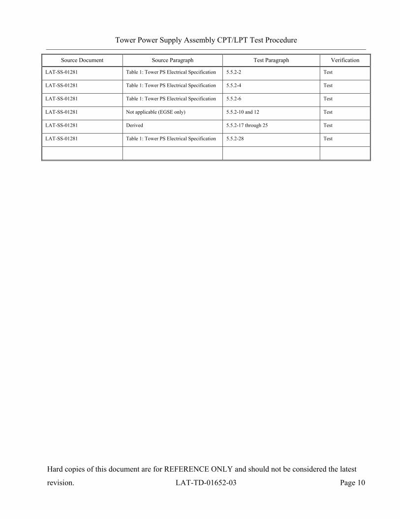
4.2 Specific Test Requirements
This document verifies the requirements from the following:
Source Document Source Paragraph Test Paragraph Verification
LAT-SS-01281: Tower Power
Supply Specification and ICD
5.1: Functional Description 5.5.1-16 through 26 Test
LAT-SS-01281 5.1: Functional Description and
Table 1: Tower PS Electrical Specification
5.5.1-27 through 33 Test
LAT-SS-01281 Table 1: Tower PS Electrical Specification 5.5.1-34 through 37 Test
LAT-SS-01281 Derived 5.5.1-39 Test
LAT-SS-01281 5.1: Functional Description and
Table 1: Tower PS Electrical Specification
5.5.1-40 and 42 Test
LAT-SS-01281 5.1: Functional Description and
Table 1: Tower PS Electrical Specification
5.5.1-44 Test
Page 11
Tower Power Supply Assembly CPT/LPT Test Procedure
Hard copies of this document are for REFERENCE ONLY and should not be considered the latest
revision. LAT-TD-01652-03 Page 10
Source Document Source Paragraph Test Paragraph Verification
LAT-SS-01281 Table 1: Tower PS Electrical Specification 5.5.2-2 Test
LAT-SS-01281 Table 1: Tower PS Electrical Specification 5.5.2-4 Test
LAT-SS-01281 Table 1: Tower PS Electrical Specification 5.5.2-6 Test
LAT-SS-01281 Not applicable (EGSE only) 5.5.2-10 and 12 Test
LAT-SS-01281 Derived 5.5.2-17 through 25 Test
LAT-SS-01281 Table 1: Tower PS Electrical Specification 5.5.2-28 Test
Page 12
Tower Power Supply Assembly CPT/LPT Test Procedure
Hard copies of this document are for REFERENCE ONLY and should not be considered the latest
revision. LAT-TD-01652-03 Page 11
4.3 Test Personnel and Descriptions
Test personnel are described in GLAST LAT Integration and Test Subsystem Test Plan, LAT-MD-
01376.
4.4 Test Readiness Review (TRR) and Post Test Review (PTR)
The TRR and PTR are organizational meetings that shall be held at the appropriate times to inform
all parties about the testing that is to be accomplished and has been completed. The TRR and PTR
meetings are defined in the GLAST LAT Integration and Test Subsystem Test Plan, LAT-MD-
01376.
4.5 Environmental Conditions
Testing performed in accordance with this document shall conform to standard environmental test
conditions unless specific test requirements within this document exist. Standard Environmental test
conditions are as follows:
• Dynamic Mechanical Conditions: No load, at rest
• Temperature: 18.3 to 25.7°C
• Atmospheric Pressure: Uncontrolled local conditions
• Humidity: 30% to 50% RH for testing when the Calorimeter or Engineering Model (EM)
Calorimeters are present. For all other testing 30% to 60% RH is required.
This document shall follow the LAT Environmental Specification, LAT-SS-00778 for all testing
where non standard environments are required. The Environmental Specification defines the
thermal, vibration and on-orbit exposure design and test environments for the LAT instrument and
its subsystems.
Page 13
Tower Power Supply Assembly CPT/LPT Test Procedure
Hard copies of this document are for REFERENCE ONLY and should not be considered the latest
revision. LAT-TD-01652-03 Page 12
4.6 Contamination Control
The Contamination Control Plan defines the overall contamination control requirements necessary to
establish hardware cleanliness for the GLAST LAT program. When work is performed at SLAC,
follow LAT-MD-01386. When work is performed elsewhere, follow LAT-MD-00404.
4.7 Handling and Transportation
This document shall follow the requirements found in the Handling, Storage, Package, Preservation
and Delivery document, LAT-MD-00473. This document establishes handling, storage, packaging
and transportation practices adequate to maintain the safety, reliability and quality of SLAC LAT
flight hardware items and achieve their damage free delivery to the place and time of ultimate use.
4.8 ESD
The CAL, TKR, T & DF Contamination Control Plan and the LAT Contamination Control Plan
define the ESD requirements for the GLAST LAT program. When work is performed at SLAC
follow LAT-MD-01386. When work is performed elsewhere follow LAT-MD-00404.
4.9 Mate/Demate Connectors
This document shall follow the requirements found in the Mate and Demate Workmanship Standard
LAT-PS-04459. The mate/demate process shall be followed for each and every connector mate. This
consists of a visual inspection of the interface, cleaning if required, and proper mating techniques.
4.10 Test Equipment
This document shall follow the requirements found in the LAT Program Instrument Performance
Verification Plan, LAT-MD-00408, which defines calibration, accuracy, substitutions, etc. for the
test equipment.
Page 14
Tower Power Supply Assembly CPT/LPT Test Procedure
Hard copies of this document are for REFERENCE ONLY and should not be considered the latest
revision. LAT-TD-01652-03 Page 13
4.11 Test Data and Review
This document shall follow the requirements found in the LAT Program Instrument Performance
Verification Plan, LAT-MD-00408, which defines the test data sheets and details the personnel that
reviews test data. Test data shall be recorded on the data sheets that are found in Appendix A of this
document. The data sheets and any supporting data shall use a cover sheet that is found in Appendix
A of this document.
4.12 Flight Hardware Log Book
The LAT Program Instrument Performance Verification Plan, LAT-MD-00408 requires that a log of
hardware installation, software installation, power ON and mates/demates to flight connectors shall
be kept for each flight unit. The log book is part of the package that is deliverable to the customer.
4.13 Nonconforming Test Data, Equipment and Software
This document shall follow the requirements found in the Control of Nonconforming Product, LAT-
MD-00471. This document establishes methods to identify and control nonconforming product
developed by the LAT project team.
4.14 Redlines to Documents
The users of this document shall follow the requirements found in the Requirements for Creating and
Using Redlines for GLAST LAT Documents and Drawings, LAT-MD-03474.
Page 15
Tower Power Supply Assembly CPT/LPT Test Procedure
Hard copies of this document are for REFERENCE ONLY and should not be considered the latest
revision. LAT-TD-01652-03 Page 14
4.15 Quality Assurance
This document shall follow the requirements found in the Corrective and Preventative Action
document, LAT-MD-00472 and the GLAST Quality Manual, LAT-MD-00091 and LAT Program
Instrument Performance Verification Plan, LAT-MD-00408.
The Corrective and Preventative Action document establishes the method to be used to initiate,
implement, evaluate and record corrective and preventive actions. The GLAST Quality Manual
defines the methods implemented by the GLAST LAT project to ensure consistent quality of all
processes for procurement, design, development and production of flight hardware, flight software,
calibration and all associated ground support equipment interfacing with flight hardware and
software. The LAT Program Instrument Performance Verification Plan defines test configuration,
data sheets and review of test results.
4.15.1 Product Assurance Requirements
The Quality Assurance Engineer (QAE) shall witness the initial test setup and validation operations.
In the event of a failure a Non Conformance Report (NCR) shall be written. The root cause and
corrective action shall be identified and there shall be QAE approval before the operation is
continued. Any deviation from this document requires approval from the QAE as well as the Test
Conductor (TC).
Page 16
Tower Power Supply Assembly CPT/LPT Test Procedure
Hard copies of this document are for REFERENCE ONLY and should not be considered the latest
revision. LAT-TD-01652-03 Page 15
4.16 Warnings, Cautions, and Notes
The following SAFETY ALERTS are intended to create awareness of the potential safety hazards
and the steps that must be taken to avoid accidents. These same alerts are used throughout this
document to identify specific hazards that may endanger personnel and/or equipment.
Identification of every conceivable hazardous situation is impossible. Therefore, all personnel have
the responsibility to diligently exercise safe practices whenever exposed to this equipment.
WARNING: Indicates a potential hazardous situation which, if not avoided, could result in
death or injury.
CAUTION: Indicates a potential hazardous situation which, if not avoided, could result in damage
to equipment.
Note: Indicates a notification of information that is important, but not hazard related.
4.17 Safety
This document shall follow the requirements found in the GLAST LAT System Safety Program
Plan, LAT-MD-00078. This document defines all phases of the LAT program including: design,
development, fabrication, handling, transportation, storage, test, assembly and operation.
WARNING: When high voltages are present extreme care should be exercised.
Page 17
Tower Power Supply Assembly CPT/LPT Test Procedure
Hard copies of this document are for REFERENCE ONLY and should not be considered the latest
revision. LAT-TD-01652-03 Page 16
4.18 Crane Operations
Before a crane (or any lifting device) is used it should be verified that the proof loading is current
and the expected load to be lifted does not exceed the load capacity of the device. The operator shall
have a current certification for the operation.
There shall be three people present before, during and at the completion of all lifting operations.
Each one of these people shall perform only one of the following three duties:
• Crane Operator – When the crane operator controls the crane no other duties shall be
performed. At other times this person may help with the mechanical or electrical duties.
• Spotter – During the lifting operation this person guides the item that is to be moved up or
down, checks clearances and the overall movement of all items. At other times this person
may help with the mechanical or electrical duties.
• Safety Person (for crane operations only) – Before lifting the item, this person double checks
all operations and the removal of bolts/hardware from the item to be moved. During crane
operations this person is an observer of the operation and directs the overall lifting operation.
Page 18
Tower Power Supply Assembly CPT/LPT Test Procedure
Hard copies of this document are for REFERENCE ONLY and should not be considered the latest
revision. LAT-TD-01652-03 Page 17
5. PROCEDURE
This procedure is used for Performance Testing of the circuits that provide power to the three main
parts of the tower assembly. This document also tests the temperatures that are part of the TPS
circuits.
Unless otherwise noted use a DVM for all measurements. Some measurements require the use of an
oscilloscope or a true Root Mean Squared (RMS) volt meter.
Note: When performing measurements with a DMM connect the negative lead first.
5.1 Test Procedure Instructions/Information
This section provides the general instructions and information that is used and required to perform
this procedure, including: test parameters, sequence, equipment and Test Participants.
5.1.1 Test Prerequisites
This section describes processes and procedures that must be completed prior to performing the tests
in this document.
• TPS Electrical Interface Continuity and Isolation Test (EICIT): LAT-TD-04090
• TPS Stray Voltage Test (SVT): LAT-TD-04849
• TPS Interface Verification Test (SVT): LAT-TD-04098
• Safe Process for TPS Electrical Ground Support Equipment (EGSE) Validation:
LAT-TD-04080
5.1.2 Test Sequence
This section describes the requirements of the event sequence for performing this procedure. Tests
are to be performed in the order listed in this document unless otherwise specified. It is permissible
for Assembly Instruction Data Sheets (AIDS) to be used to change the order of tests or select a
single test paragraph to be performed. In that case, the data sheet for the test performed will be
included in the end item data package linked to the AIDS step that required it. Test sequencing can
also be changed in a TRR and black lined into the test procedure.
Page 19
Tower Power Supply Assembly CPT/LPT Test Procedure
Hard copies of this document are for REFERENCE ONLY and should not be considered the latest
revision. LAT-TD-01652-03 Page 18
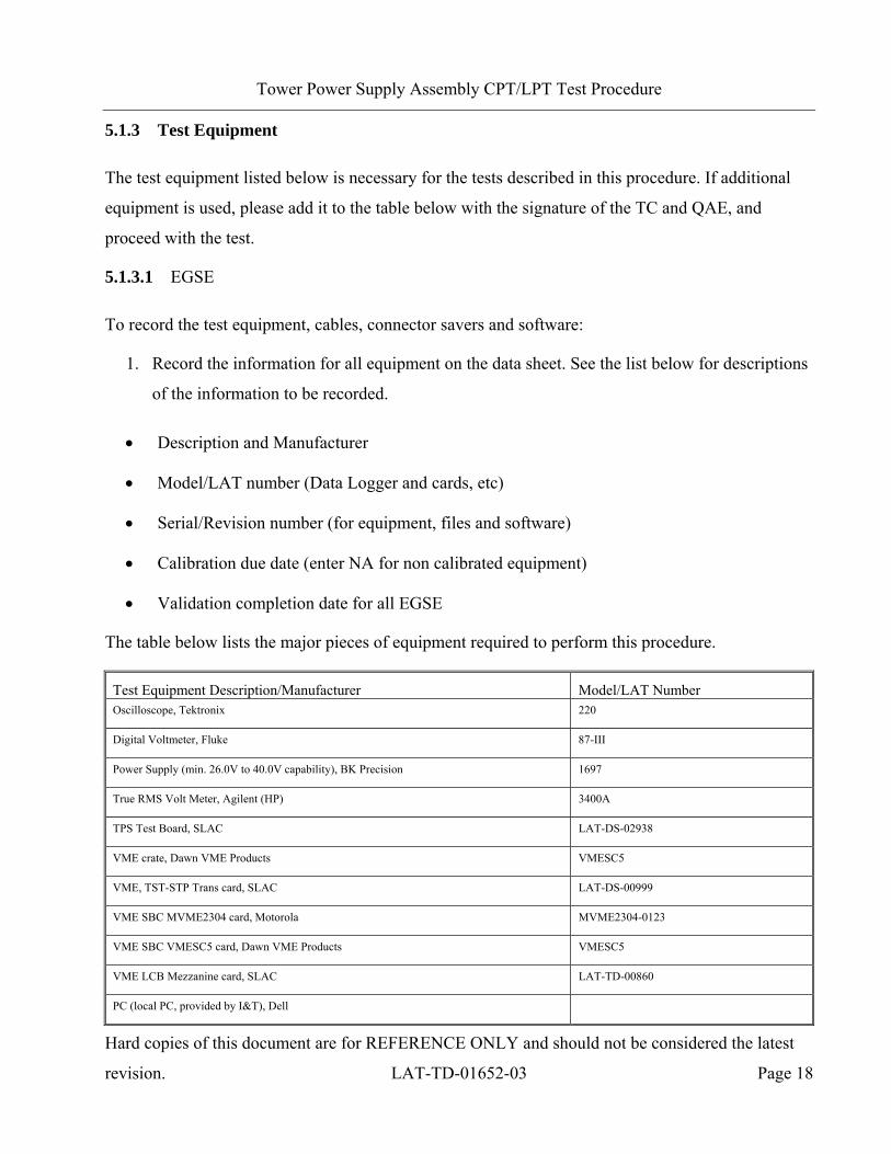
5.1.3 Test Equipment
The test equipment listed below is necessary for the tests described in this procedure. If additional
equipment is used, please add it to the table below with the signature of the TC and QAE, and
proceed with the test.
5.1.3.1 EGSE
To record the test equipment, cables, connector savers and software:
1. Record the information for all equipment on the data sheet. See the list below for descriptions
of the information to be recorded.
• Description and Manufacturer
• Model/LAT number (Data Logger and cards, etc)
• Serial/Revision number (for equipment, files and software)
• Calibration due date (enter NA for non calibrated equipment)
• Validation completion date for all EGSE
The table below lists the major pieces of equipment required to perform this procedure.
Test Equipment Description/Manufacturer Model/LAT Number Oscilloscope, Tektronix 220
Digital Voltmeter, Fluke 87-III
Power Supply (min. 26.0V to 40.0V capability), BK Precision 1697
True RMS Volt Meter, Agilent (HP) 3400A
TPS Test Board, SLAC LAT-DS-02938
VME crate, Dawn VME Products VMESC5
VME, TST-STP Trans card, SLAC LAT-DS-00999
VME SBC MVME2304 card, Motorola MVME2304-0123
VME SBC VMESC5 card, Dawn VME Products VMESC5
VME LCB Mezzanine card, SLAC LAT-TD-00860
PC (local PC, provided by I&T), Dell
Page 20
Tower Power Supply Assembly CPT/LPT Test Procedure
Hard copies of this document are for REFERENCE ONLY and should not be considered the latest
revision. LAT-TD-01652-03 Page 19
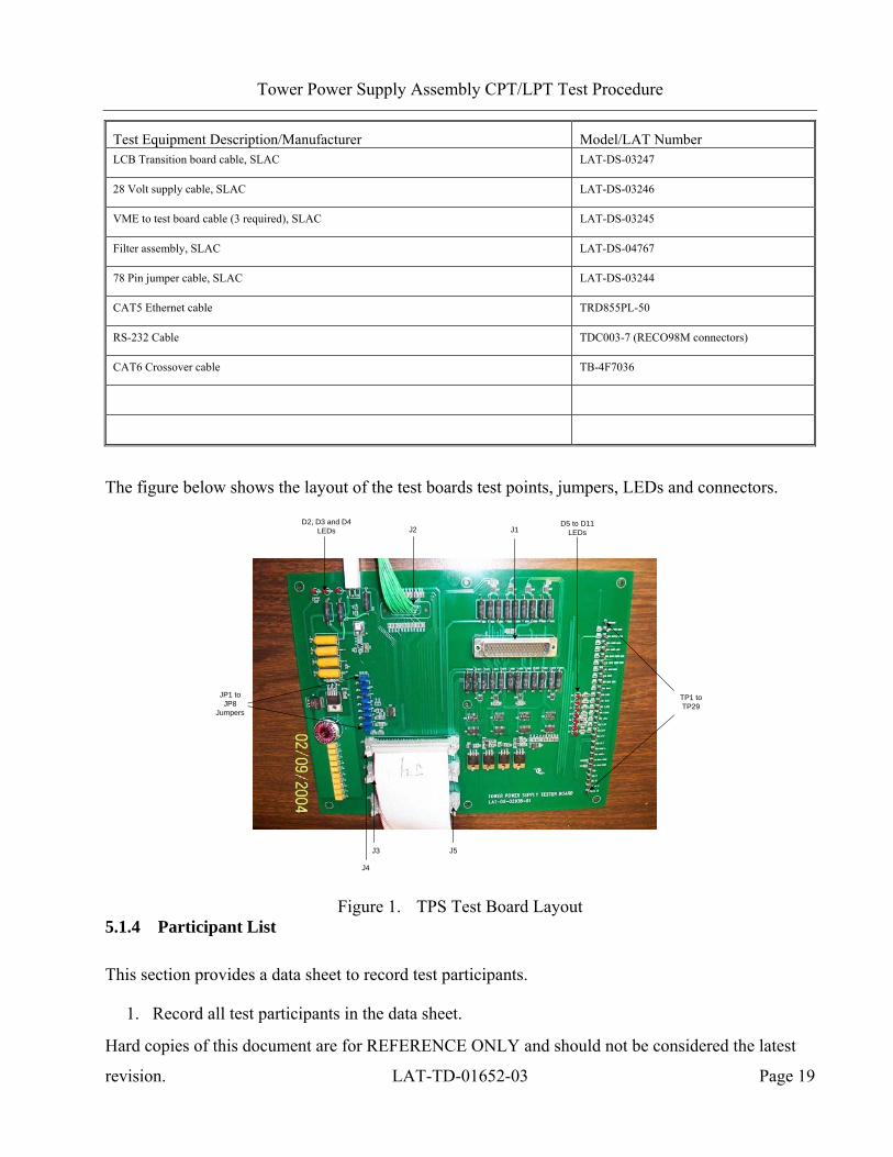
Test Equipment Description/Manufacturer Model/LAT Number LCB Transition board cable, SLAC LAT-DS-03247
28 Volt supply cable, SLAC LAT-DS-03246
VME to test board cable (3 required), SLAC LAT-DS-03245
Filter assembly, SLAC LAT-DS-04767
78 Pin jumper cable, SLAC LAT-DS-03244
CAT5 Ethernet cable TRD855PL-50
RS-232 Cable TDC003-7 (RECO98M connectors)
CAT6 Crossover cable TB-4F7036
The figure below shows the layout of the test boards test points, jumpers, LEDs and connectors.
D2, D3 and D4LEDs J2 J1
TP1 to TP29
D5 to D11LEDs
J4
JP1 to JP8
Jumpers
J3 J5
Figure 1. TPS Test Board Layout 5.1.4 Participant List
This section provides a data sheet to record test participants.
1. Record all test participants in the data sheet.
Page 21
Tower Power Supply Assembly CPT/LPT Test Procedure
Hard copies of this document are for REFERENCE ONLY and should not be considered the latest
revision. LAT-TD-01652-03 Page 20
5.2 Test Setup
The Figure below is a block diagram of the TPS test setup.
TPS
Test/Load Board
PowerSupply
VMELocal PC
O-Scope
True RMS Volt Meter
DVM
Figure 2. TPS Test Setup Block Diagram
Page 22
Tower Power Supply Assembly CPT/LPT Test Procedure
Hard copies of this document are for REFERENCE ONLY and should not be considered the latest
revision. LAT-TD-01652-03 Page 21
5.2 Test Setup (continued)
The Figure below shows the test configuration of the equipment, cables and connections for testing.
VME
LAT-DS-03245
LAT-DS-03245
DC Power Supply
(+)
(-)
Local network connectionLocal PC
Slot 0SBC MVME 2304 Card
10/100Base
Debug
To LCBEVENT
To LCBCMD
LAT-DS-03247
Serial port connection and adapter
LAT-DS-03246
J1
J2
J3
Test BoardLAT-DS-02938
LAT-DS-03245
P2
P2
P2
TPSEquipment under test
LAT-DS-03244Test board pigtail
True RMS Volt Meter
O-Scope
DVM
This equipment is used for taking measurements at test points on the test board as called out by the procedure.
TPS pigtail TPS pigtail
J5
J4
J3
J6
J2
P1
P1
P2
J2
J1
J1
J2
Off the shelf test leads
LAT-DS-04767Filter Assy.
LCB Mezzanine CardLAT-TD-00860
Slot 4 TST-STP Trans CardLAT-DS-00999
J20
P1
P1
J18P1
J19
Dawn VMEModel VMESC5 card
190 Ohm >1 Watt resistor, provides a soft ground.
Power In J1J2 Power Out
J1 Power In Power Out J2
TDC003-7,(RECO98M Connectors)
RS-232 Cable
TRD855PL-50CAT5 Ethernet
TDC003-7,(RECO98M Connectors)
RS-232 Cable
Network card
CAT6 Crossover Cable
Note: For Network connection use a) Local network connection or b) Crossover cable.
Figure 3. Test Setup Interconnection Diagram
Note: The TPS board and TPS box have different labeling for J1 and J2.
Page 23
Tower Power Supply Assembly CPT/LPT Test Procedure
Hard copies of this document are for REFERENCE ONLY and should not be considered the latest
revision. LAT-TD-01652-03 Page 22
5.2 Test Setup (continued)
The Figure below shows the external power supply that is used in this document.
RecallProg.
EnterClear
Output Switch condition indicator
Shift
O/P on/off
RS-232/485 Lock/Unlock
Figure 4. External Power Supply
Page 24
Tower Power Supply Assembly CPT/LPT Test Procedure
Hard copies of this document are for REFERENCE ONLY and should not be considered the latest
revision. LAT-TD-01652-03 Page 23
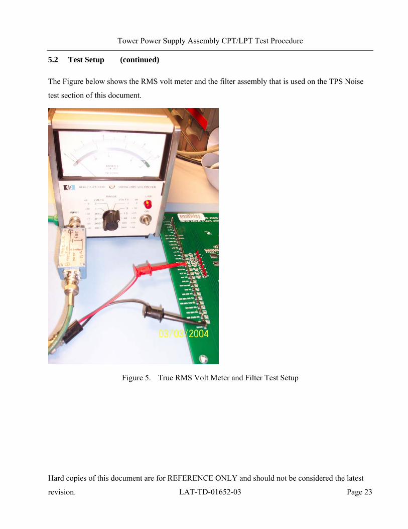
5.2 Test Setup (continued)
The Figure below shows the RMS volt meter and the filter assembly that is used on the TPS Noise
test section of this document.
Figure 5. True RMS Volt Meter and Filter Test Setup
Page 25
Tower Power Supply Assembly CPT/LPT Test Procedure
Hard copies of this document are for REFERENCE ONLY and should not be considered the latest
revision. LAT-TD-01652-03 Page 24
5.2.1 Pre-Operation Verifications
This section details the pre-operation verification checks before testing the EUT.
To perform the pre-operation verification checks:
CAUTION: Follow ESD processes during this checkout.
Note: Prior to the connection of any hardware to other electronics, it shall be verified that
all power supplies, signal generators, VME racks, and any other test and
measurement equipment shall be connected to the same AC ground. The simplest
way to do this is to connect all AC-powered equipment to the same power strip. In
cases where this is not practical (e.g. possibly a thermal-vacuum test), greater care
must be taken to ensure there are no floating grounds since this would represent a
hazard to the electronics.
Note: Leave all connector savers in place until the actual flight mate is to be made. The
AIDS provides authorization to install and remove connector savers.
Note: All flight mates and demates must be completed and entered into the mate demate log
before measurements are made or testing can start.
1. Notify QAE that testing is expected to start, so the QAE can arrange to be present for the
setup and start of testing. Record per the data sheet.
2. Verify that the Test Readiness Review has concluded and all parties have signed the cover
sheet. Record per the data sheet.
3. Record the serial numbers and locations per the data sheet.
4. Turn off the LAT or the EGSE power. Record in the data sheet.
5. Set the DMM to the auto-ranging setting. Record in the data sheet.
6. Measure DMM lead resistance by connecting the two leads together. Record in the data sheet.
Page 26
Tower Power Supply Assembly CPT/LPT Test Procedure
Hard copies of this document are for REFERENCE ONLY and should not be considered the latest
revision. LAT-TD-01652-03 Page 25
7. Measure the resistance between the EUT chassis and technical ground. Record in the data
sheet.
8. Measure the resistance between the test equipment chassis and technical ground. Record in
the data sheet.
9. Verify connector savers are on all flight hardware (install the connector savers per
authorization from an AIDS if necessary). Record in the data sheet.
10. Verify that the test equipment and participant lists have been completed.
Page 27
Tower Power Supply Assembly CPT/LPT Test Procedure
Hard copies of this document are for REFERENCE ONLY and should not be considered the latest
revision. LAT-TD-01652-03 Page 26
5.3 Test Descriptions
Types of tests that are performed on the Equipment Under Test (EUT) in this procedure are in the
following three groups:
Subassembly (only) level tests:
• Switching Filter Test (100% load) – Checks the wave form of the 28.0 volt power input line
just after a filter that is designed to prevent TPS board noise from propagating back to the
spacecraft.
LPT testing:
• Voltage and Current Measurements (10% load) – Measures the voltages and currents.
• CAL and TKR on/off Control (10% load) – Verifies the operation of the CAL and TKR
control circuits.
• Ripple Voltage (100% load) – Measures the conducted EMI of the unit.
• Load Regulation – Tests the ability to maintain a constant output voltage with changes in
load (loads at 100% and 150%).
• Efficiency Ratio (100% load) – Compares the power input of the unit vs. the power output of
the unit.
CPT Testing:
• Line Regulation (100% load) – Tests the ability to maintain a constant output voltage with
varied line input voltages. The input voltage settings are 26.0, 28.0, 30.0 and 40.0.
• Margin Bias – Checks that the TEM, TKR and CAL voltages are stable at 100% load. For
Flight unit testing, the margin tests are not run.
• Load Response Transient (an oscillator switches between 10 and 100% loads) – Verifies
when a load is applied that the peak to peak transients are within the required levels.
• TPS Noise (100% load) – Verifies noise over a frequency of 1KHz-1MHz.
Note: CPT testing contains information on testing the EM and Flight units
Page 28
Tower Power Supply Assembly CPT/LPT Test Procedure
Hard copies of this document are for REFERENCE ONLY and should not be considered the latest
revision. LAT-TD-01652-03 Page 27
5.4 Subassembly Level Testing
This section provides the instructions for testing the TPS that is done only at the subassembly level.
The Limited Performance Test (LPT) portion of the test is run using the box level procedure and the
Comprehensive Performance Test (CPT) is run using the box level. The LPT portion contains the
setup process. The process for subassembly level testing is as follows:
• Run the LPT from Para 5.5.1.
• Run the Switching test Para 5.4.1.
• Run the CPT from Para 5.5.2.
Page 29
Tower Power Supply Assembly CPT/LPT Test Procedure
Hard copies of this document are for REFERENCE ONLY and should not be considered the latest
revision. LAT-TD-01652-03 Page 28
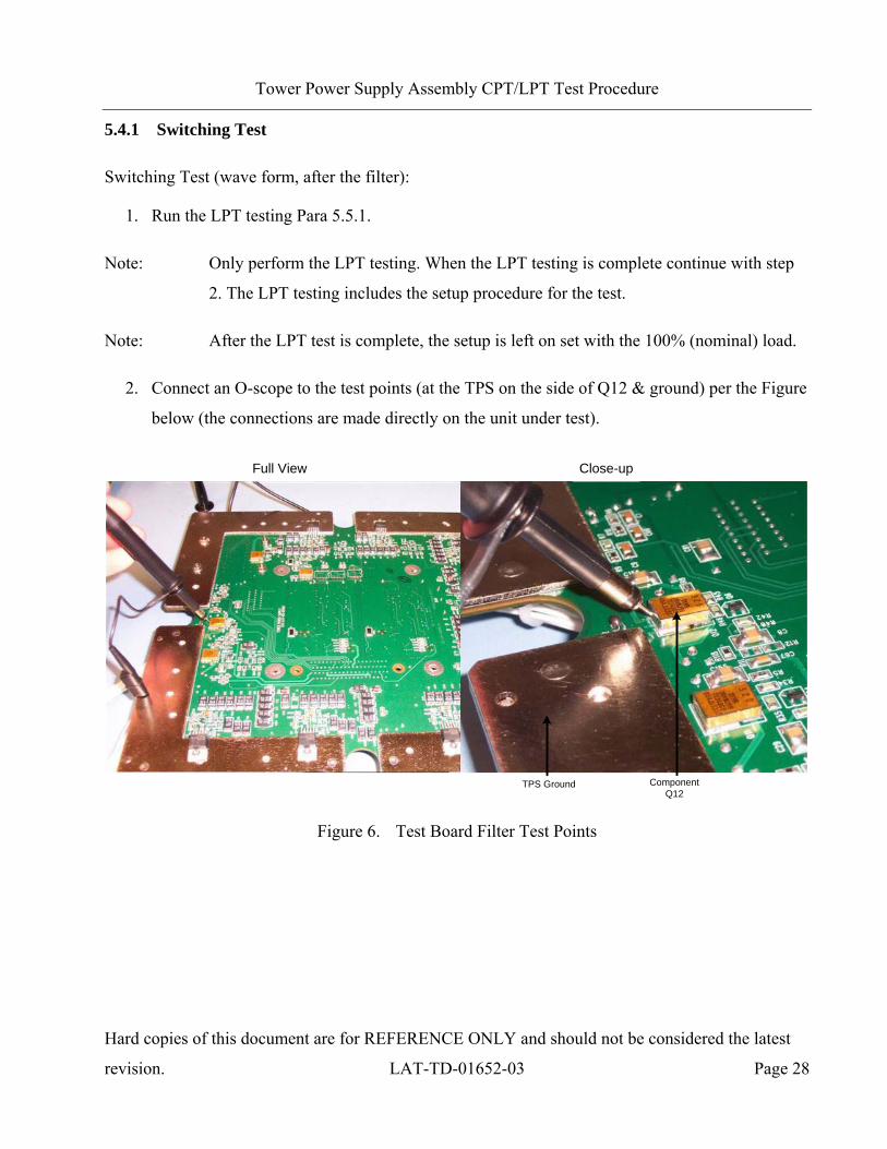
5.4.1 Switching Test
Switching Test (wave form, after the filter):
1. Run the LPT testing Para 5.5.1.
Note: Only perform the LPT testing. When the LPT testing is complete continue with step
2. The LPT testing includes the setup procedure for the test.
Note: After the LPT test is complete, the setup is left on set with the 100% (nominal) load.
2. Connect an O-scope to the test points (at the TPS on the side of Q12 & ground) per the Figure
below (the connections are made directly on the unit under test).
ComponentQ12
TPS Ground
Full View Close-up
Figure 6. Test Board Filter Test Points
Page 30
Tower Power Supply Assembly CPT/LPT Test Procedure
Hard copies of this document are for REFERENCE ONLY and should not be considered the latest
revision. LAT-TD-01652-03 Page 29
5.4.1 Switching Test (continued)
3. View and verify that the data is good. The Figure below is an example of how the signal after
the filter should look. Record per the data sheet.
Figure 7. 28 Volt Line After the Filter
Note: Verify that the band width (20MHz) limit on the scope is in the on position.
4. Run the CPT Test Procedure from Para. 5.5.2.
Page 31
Tower Power Supply Assembly CPT/LPT Test Procedure
Hard copies of this document are for REFERENCE ONLY and should not be considered the latest
revision. LAT-TD-01652-03 Page 30
5.5 LPT and CPT Unit Level Test Procedures
This procedure verifies that the TPS functions properly for the LPT and CPT tests and performs to
the levels required by the TPS specification. The LPT test portion contains the setup of the test.
Therefore when the CPT test is performed, it shall be preceded by the LPT test.
Note: Test Point 1 (TP1) is used throughout this document as the common ground for all
measurements.
Page 32
Tower Power Supply Assembly CPT/LPT Test Procedure
Hard copies of this document are for REFERENCE ONLY and should not be considered the latest
revision. LAT-TD-01652-03 Page 31
5.5 LPT and CPT Unit Level Test Procedures (continued)
There are four sections in this procedure as listed below.
Setup:
• A block diagram shows the equipment needed and an interconnect diagram identifies the
cabling starting at page 20.
• A list of equipment and the model numbers is provided at page 18.
• Verify the external power supply voltage settings.
Initialization (how to turn on the equipment and configuration):
• Boot-up the computer.
• Initialize the various settings.
Functional Tests:
• Initial voltages and currents
• Baseline voltages and currents
• LEDs Illuminated
Performance tests:
• This section tests the line regulation, load regulation, noise performance, and transient
response, etc.
Calibration measurements:
• This measures and records the calibration values for the TPS under test that are used when
the TEM and TPS are later mated up as one unit. Each TPS unit has different calibration
values that are recorded with this check.
WARNING: This procedure contains high voltages that are part of the setup and care should
be taken when measurements are made.
Page 33
Tower Power Supply Assembly CPT/LPT Test Procedure
Hard copies of this document are for REFERENCE ONLY and should not be considered the latest
revision. LAT-TD-01652-03 Page 32
5.5.1 LPT Testing
Setup:
1. Enter the serial numbers and the calibration due dates for all equipment per the data sheet.
2. Mate all cables and power connections per the interconnect diagram.
3. Power up the VME.
4. Power up the PC.
5. Open the “ttermpro” file located in the C:\Program Files\TeraTermProSSH\ directory.
6. Open a Command Prompt window. and startup the software for the test.
7. At the command prompt, on the C: drive, type in "TPS_Test.bat" and then enter.
Page 34
Tower Power Supply Assembly CPT/LPT Test Procedure
Hard copies of this document are for REFERENCE ONLY and should not be considered the latest
revision. LAT-TD-01652-03 Page 33
8. The “TPS Test” window appears for configuring the test board and equipment.
Figure 8. TPS Test Window
Page 35
Tower Power Supply Assembly CPT/LPT Test Procedure
Hard copies of this document are for REFERENCE ONLY and should not be considered the latest
revision. LAT-TD-01652-03 Page 34
5.5.1 LPT Testing (continued)
9. Disconnect the output cable (LAT-DS-03246) from the external power supply.
10. Power up the external power supply.
11. At the TPS Test window click on each of the power supply buttons to verify the voltage
output settings as listed below.
• 1.0 volt
• 28.0 volts
• 26.0 volts
• 30.0 volts
• 40.0 volts
12. Click on the “Voltage_In 1V” button to set the power supply to 1.0V.
13. Reconnect the output cable (LAT-DS-03246) to the external power supply.
Page 36
Tower Power Supply Assembly CPT/LPT Test Procedure
Hard copies of this document are for REFERENCE ONLY and should not be considered the latest
revision. LAT-TD-01652-03 Page 35
5.5.1 LPT Testing (continued)
Initialization:
The TPS Test GUI contains buttons that configure the following test board and external power
supply features:
• Main Power and Main off buttons – Control the power on/off condition of the external power
supply.
• Enable TPS, Disable TPS, Enable CAL, Disable CAL, Enable TKR and Disable TKR
buttons – Controls the on/off condition of the TPS, CAL and TKR functions.
• Set_CAL_HV_100, Set_CAL_HV_0, Set_TKR_HV_150 and Set_TKR_HV_0 buttons –
Controls Bias control settings for the CAL and TKR.
• Enable_90%_LD, Disable_90%_LD, Enable_50%_LD and Disable_50%_LD buttons –
Controls the 90% and 50% test loads. When all the loads disabled the test board is configured
for a 10% nominal load.
• Enable_Osc and Disable_Osc buttons – Controls the test oscillator.
• Set_Nom_Margin, Set_Low_Margin and Set_HI_Margin buttons – Controls the margin
settings.
• Read all values – This creates a list of all readings (i.e. voltages) in the command prompt
window.
14. At the TPS Test window, click on “Disable_Osc”, “Disable_90%_LD”, “Disable_50%_LD”,
“Set_CAL_HV_0”, “Set_TKR_HV_0”, “Disable CAL”, “Disable TKR”, “Disable TPS” and
“Main Off”.
Note: Upon powering on the test board, the configuration is the state it was in before it was
last powered off. Therefore all the complete configuration commands and settings
shall be performed prior to starting this test.
Page 37
Tower Power Supply Assembly CPT/LPT Test Procedure
Hard copies of this document are for REFERENCE ONLY and should not be considered the latest
revision. LAT-TD-01652-03 Page 36
5.5.1 LPT Testing (continued)
Functional Tests, LEDs Illuminated Verifications:
15. At the TPS Test window, click on the “Voltage_In 28V” button.
16. At the test board verify that LEDs D2 (VDD, power to the test board) and D3 (28_IN) are
illuminated. Record the values per the data sheet.
17. Monitor the external power supply current level. Record the values per the data sheet.
18. At the TPS Test window, click on the “Enable TPS” button to turn the DAC on.
19. Verify that LEDs D4 (28_OUT), D10 (TEM 2.5) and D11 (TEM 3.3) are illuminated. Record
the values per the data sheet.
20. Monitor the external power supply current level. Record the values per the data sheet.
21. At the TPS Test window, click on the “Enable CAL” button.
22. Verify that LEDs D5 (CAL 3.3 Analog) and D6 (CAL 3.3 digital) are illuminated. Record the
values per the data sheet.
23. Monitor the external power supply current level. Record the values per the data sheet.
24. At the TPS Test window, click on the “Enable TKR” button.
25. Verify that LEDs D7 (TKR 2.65 digital), D8 (TKR 2.65 analog) and D9 (TKR 1.5 analog) are
illuminated. Record the values per the data sheet.
26. Monitor the external power supply current level. Record the values per the data sheet.
Page 38
Tower Power Supply Assembly CPT/LPT Test Procedure
Hard copies of this document are for REFERENCE ONLY and should not be considered the latest
revision. LAT-TD-01652-03 Page 37
5.5.1 LPT Testing (continued)
Functional Test Point Measurements:
The command window shows the voltages for the test board, as shown in the Figure below.
Figure 9. Command Window Measurements
27. Measure the DC voltage for the 28V Current Monitor Test Point (TP2). This voltage
measurement indicates the current in this circuit. Record the values per the data sheet.
Note: TP1 is used throughout this document as the common ground for most measurements.
28. Measure the TEM high and low voltage for the TEM Current High and Low (TP4, TP5).
These voltage measurements indicate the current in this circuit. Record the values per the
data sheet.
29. Measure the TKR Bias (set to zero scale) monitors (TP6, TP10). Voltage measurement TP6
(TKR Bias Current Monitor) indicates the current in this circuit. Record the values per the
data sheet.
Page 39
Tower Power Supply Assembly CPT/LPT Test Procedure
Hard copies of this document are for REFERENCE ONLY and should not be considered the latest
revision. LAT-TD-01652-03 Page 38
5.5.1 LPT Testing (continued)
30. Measure the CAL Bias (set to zero scale) monitors (TP7, TP8). Voltage measurement TP7
(CAL Bias Current Monitor) indicates the current in this circuit. Record the values per the
data sheet.
31. At the TPS Test window, click on the “Set_CAL_HV_100” & “Set_TKR_HV_150” buttons.
32. Measure the TKR Bias (set to full scale) monitors (TP6, TP10). Voltage measurement TP6
(TKR Bias Current Monitor) indicates the current in this circuit. Record the values per the
data sheet.
33. Measure the CAL Bias (set to full scale) monitors (TP7, TP8) and the external power supply.
Voltage measurement TP7 (CAL Bias Current Monitor) indicates the current in this circuit.
Record the values per the data sheet.
Page 40
Tower Power Supply Assembly CPT/LPT Test Procedure
Hard copies of this document are for REFERENCE ONLY and should not be considered the latest
revision. LAT-TD-01652-03 Page 39
5.5.1 LPT Testing (continued)
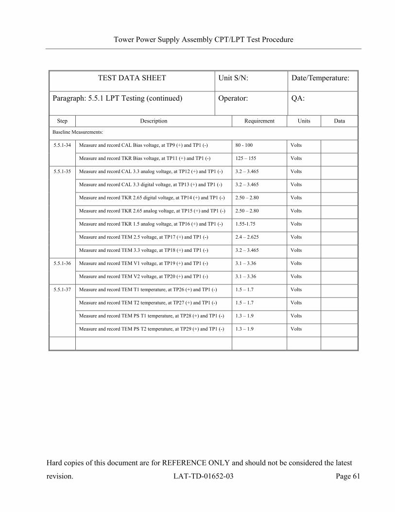
Baseline Measurements:
34. Measure the CAL and TKR Bias voltages (TP9 & TP11). Record the values per the data
sheet.
35. Measure the CAL, TKR and TEM analog and digital voltages (TP12-TP18). Record the
values per the data sheet.
36. Measure the TEM V1 and V2 voltages (TP19-TP20). Record the values per the data sheet.
37. Measure the four temperature readings, two for the unit under test and two are simulated TEM
temperatures (TP26-TP29). Record the values per the data sheet.
Page 41
Tower Power Supply Assembly CPT/LPT Test Procedure
Hard copies of this document are for REFERENCE ONLY and should not be considered the latest
revision. LAT-TD-01652-03 Page 40
5.5.1 LPT Testing (continued)
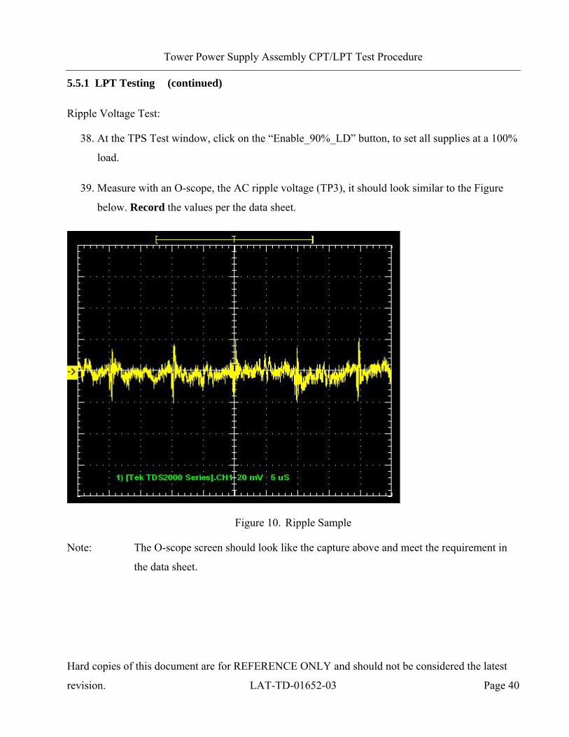
Ripple Voltage Test:
38. At the TPS Test window, click on the “Enable_90%_LD” button, to set all supplies at a 100%
load.
39. Measure with an O-scope, the AC ripple voltage (TP3), it should look similar to the Figure
below. Record the values per the data sheet.
Figure 10. Ripple Sample
Note: The O-scope screen should look like the capture above and meet the requirement in
the data sheet.
Page 42
Tower Power Supply Assembly CPT/LPT Test Procedure
Hard copies of this document are for REFERENCE ONLY and should not be considered the latest
revision. LAT-TD-01652-03 Page 41
5.5.1 LPT Testing (continued)
Load Regulation Test:
40. Measure the nine CAL, TKR and TEM supply voltages (TP9, TP11-TP18) and current at the
external power supply. This step uses the baseline measurements to calculate the delta.
Record the values per the data sheet.
41. At the TPS Test window, click on the “Enable_50%_LD” button, to set all supplies at a 150%
load.
42. Measure the nine CAL, TKR and TEM supply voltages (TP9, TP11-TP18) and current at the
external power supply. This step uses the baseline measurements to calculate the delta.
Record the values per the data sheet.
43. At the TPS Test window, click on the “Disable_50%_LD” buttons, to set all supplies to the
100% (nominal) load.
Efficiency Test:
44. Record the external power supply current level for the efficiency test per the data sheet.
Page 43
Tower Power Supply Assembly CPT/LPT Test Procedure
Hard copies of this document are for REFERENCE ONLY and should not be considered the latest
revision. LAT-TD-01652-03 Page 42
5.5.2 CPT Testing
Line Regulation Test:
1. At the TPS Test window, click on the “Enable_90%_LD” and “Voltage_In 26V” buttons, to
set all supplies to the 100% (nominal) load and 26 input volts.
2. Measure the nine CAL, TKR and TEM supply voltages (TP9, TP11-TP18) and current at the
external power supply. This step uses the baseline measurements to calculate the delta.
Record the values per the data sheet.
3. At the TPS Test window, click on the “Voltage_In 30V” button.
4. Measure the nine CAL, TKR and TEM supply voltages (TP9, TP11-TP18) and current at the
external power supply. This step uses the baseline measurements to calculate the delta.
Record the values per the data sheet.
5. At the TPS Test window, click on the “Voltage_In 40V” button.
6. Measure the nine CAL, TKR and TEM supply voltages (TP9, TP11-TP18) and current at the
external power supply. This step uses the baseline measurements to calculate the delta.
Record the values per the data sheet.
7. At the TPS Test window, click on the “Voltage_In 28V” button.
Page 44
Tower Power Supply Assembly CPT/LPT Test Procedure
Hard copies of this document are for REFERENCE ONLY and should not be considered the latest
revision. LAT-TD-01652-03 Page 43
5.5.2 CPT Testing (continued)
Margin Test:
Note: Do not run the margin tests for Flight unit testing.
8. At the TPS Test window, click on the “Enable_90%_LD” button.
9. Click on the “Set_Low_Margin” button.
10. Measure the seven CAL, TKR and TEM supply voltages (TP12-TP18) and current at the
external power supply. Record the values per the data sheet.
11. Click on the “Set_HI_Margin” button.
12. Measure the seven CAL, TKR and TEM supply voltages (TP12-TP18) and current at the
external power supply. Record the values per the data sheet.
13. Click on the “Set_Nom_Margin” button, to set the margin to nominal.
Page 45
Tower Power Supply Assembly CPT/LPT Test Procedure
Hard copies of this document are for REFERENCE ONLY and should not be considered the latest
revision. LAT-TD-01652-03 Page 44
5.5.2 CPT Testing (continued)
Load Response Transient Test:
14. At the TPS Test window, click on the “Disable_90%_LD” button.
15. Click on the “Enable_Osc” button.
The oscillator cycles the load in and out of a 10% to 100% load condition.
16. Connect the scope triggers to the TP9, 11-18 use CH1 and TP25 toCH2 (for all
measurements).
Note: Verify that the scope probe and scope are set at 10X for the 10X test leads.
Page 46
Tower Power Supply Assembly CPT/LPT Test Procedure
Hard copies of this document are for REFERENCE ONLY and should not be considered the latest
revision. LAT-TD-01652-03 Page 45
5.5.2 CPT Testing (continued)
Load Response Transient Test (continued)
The next two Figures are examples of the Engineering Model (EM) and Flight digital transients as
viewed on a scope.
Note: Use the appropriate Figure for the test being performed.
Figure 11. EM Digital Load Response Transient Test
Page 47
Tower Power Supply Assembly CPT/LPT Test Procedure
Hard copies of this document are for REFERENCE ONLY and should not be considered the latest
revision. LAT-TD-01652-03 Page 46
5.5.2 CPT Testing (continued)
Load Response Transient Test (continued)
Figure 12. Flight Digital Load Response Transient Test
Page 48
Tower Power Supply Assembly CPT/LPT Test Procedure
Hard copies of this document are for REFERENCE ONLY and should not be considered the latest
revision. LAT-TD-01652-03 Page 47
5.5.2 CPT Testing (continued)
Load Response Transient Test (continued)
The next two Figures are examples of the EM and Flight unit analog transients as viewed on a scope.
Note: Use the appropriate Figure for the test being performed.
Figure 13. EM Analog Load Response Transient Test
Page 49
Tower Power Supply Assembly CPT/LPT Test Procedure
Hard copies of this document are for REFERENCE ONLY and should not be considered the latest
revision. LAT-TD-01652-03 Page 48
5.5.2 CPT Testing (continued)
Load Response Transient Test (continued)
Figure 14. Flight Analog Load Response Transient Test
Page 50
Tower Power Supply Assembly CPT/LPT Test Procedure
Hard copies of this document are for REFERENCE ONLY and should not be considered the latest
revision. LAT-TD-01652-03 Page 49
5.5.2 CPT Testing (continued)
Load Response Transient Test (continued)
The Figure below is an example of the EM and Flight unit CAL bias transients as viewed on a scope.
Figure 15. EM and Flight CAL Bias Load Response Transient Test
Page 51
Tower Power Supply Assembly CPT/LPT Test Procedure
Hard copies of this document are for REFERENCE ONLY and should not be considered the latest
revision. LAT-TD-01652-03 Page 50
5.5.2 CPT Testing (continued)
Load Response Transient Test (continued)
The Figure below is an example of the EM and Flight unit TKR bias transients as viewed on a scope.
Figure 16. EM and Flight TKR Bias Load Response Transient Test
Page 52
Tower Power Supply Assembly CPT/LPT Test Procedure
Hard copies of this document are for REFERENCE ONLY and should not be considered the latest
revision. LAT-TD-01652-03 Page 51
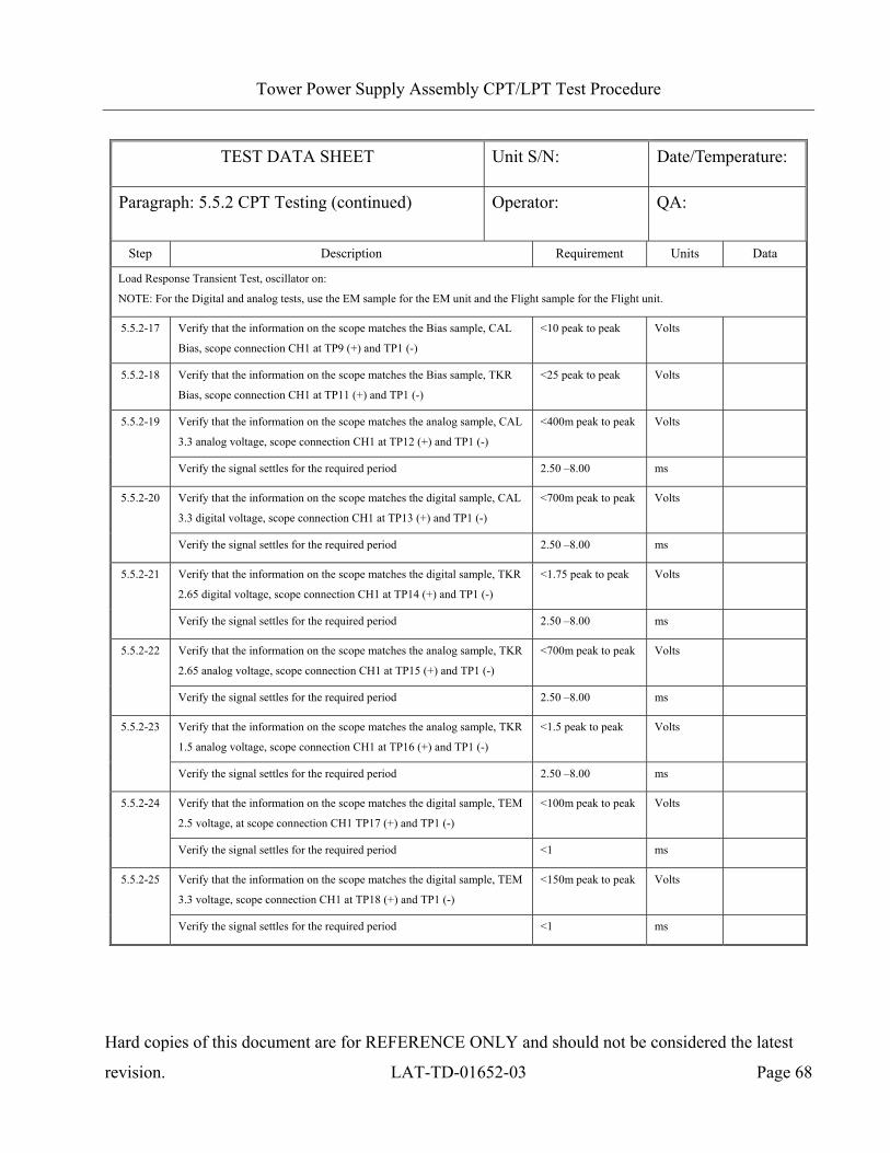
5.5.2 CPT Testing (continued)
Load Response Transient Test (continued)
For this test the scope probe is connected to each of the seven voltages each in succession. The
oscillator cycles through all the circuits creating transients that are viewed at the test points. The first
measurement is made then the scope trigger is reset and then the other test points are measured.
17. View and verify that the data is good per the sample in Figure 15, for CAL Bias supply
voltage (TP9). Record per the data sheet.
18. View and verify that the data is good per the sample in Figure 16, for TKR Bias supply
voltage (TP11). Record per the data sheet.
19. View and verify that the data is good per the sample in Figure 13, for CAL 3.3 analog supply
voltage (TP12). Record per the data sheet.
20. View and verify that the data is good per the sample in Figure 11, for CAL 3.3 digital supply
voltage (TP13). Record per the data sheet.
21. View and verify that the data is good per the sample in Figure 11, for TKR 2.65 digital supply
voltage (TP14). Record per the data sheet.
22. View and verify that the data is good per the sample in Figure 13, for TKR 2.65 analog supply
voltage (TP15). Record per the data sheet.
23. View and verify that the data is good per the sample in Figure 13, for TKR 1.5 analog supply
voltage (TP16). Record per the data sheet.
24. View and verify that the data is good per the sample in Figure 13, for TEM 2.5 supply voltage
(TP17). Record per the data sheet.
25. View and verify that the data is good per the sample in Figure 13, for TEM 3.3 supply voltage
(TP18). Record per the data sheet.
26. At the TPS Test window, click on the “Disable_Osc” button.
Page 53
Tower Power Supply Assembly CPT/LPT Test Procedure
Hard copies of this document are for REFERENCE ONLY and should not be considered the latest
revision. LAT-TD-01652-03 Page 52
5.5.2 CPT Testing (continued)
TPS Noise Test:
27. At the TPS Test window, click on the “Enable_90%_LD” button (to set the load at 100%).
28. Measure (with the HP3400A true RMS volt meter) and record the TPS noise on all nine
voltages (including the bias voltages). Record the values per the data sheet.
29. If testing is to be continued for other units go back to LPT Para 5.5.1, step 15 and re-run this
procedure.
30. When testing is complete shut down all equipment and then disconnect the cables.
Page 54
Tower Power Supply Assembly CPT/LPT Test Procedure
Hard copies of this document are for REFERENCE ONLY and should not be considered the latest
revision. LAT-TD-01652-03 Page 53
Appendix A (Data Sheets and Covers)
Page 55
Tower Power Supply Assembly CPT/LPT Test Procedure
Hard copies of this document are for REFERENCE ONLY and should not be considered the latest
revision. LAT-TD-01652-03 Page 54
COVER SHEET
Program: GLAST
Procedure Number: LAT-TD-01652
Procedure Title: TPS Performance Test Procedure
Controlling Document Number:
Controlling Document Step Number:
Unit S/N:
Descriptive Comment:
TEST READINESS REVIEW COMPLETED AND APPROVED BY THE FOLLOWING:
Test Director: Date:
Quality Assurance: Date:
Test Conductor: Date:
REVIEWED AND APPROVED BY THE FOLLOWING:
Test Director: Date:
Quality Assurance: Date:
Test Conductor: Date:
Page 56
Tower Power Supply (TPS) Performance Test Procedure
Hard copies of this document are for REFERENCE ONLY and should not be considered the latest
revision. LAT-TD-01652-03 Page 55
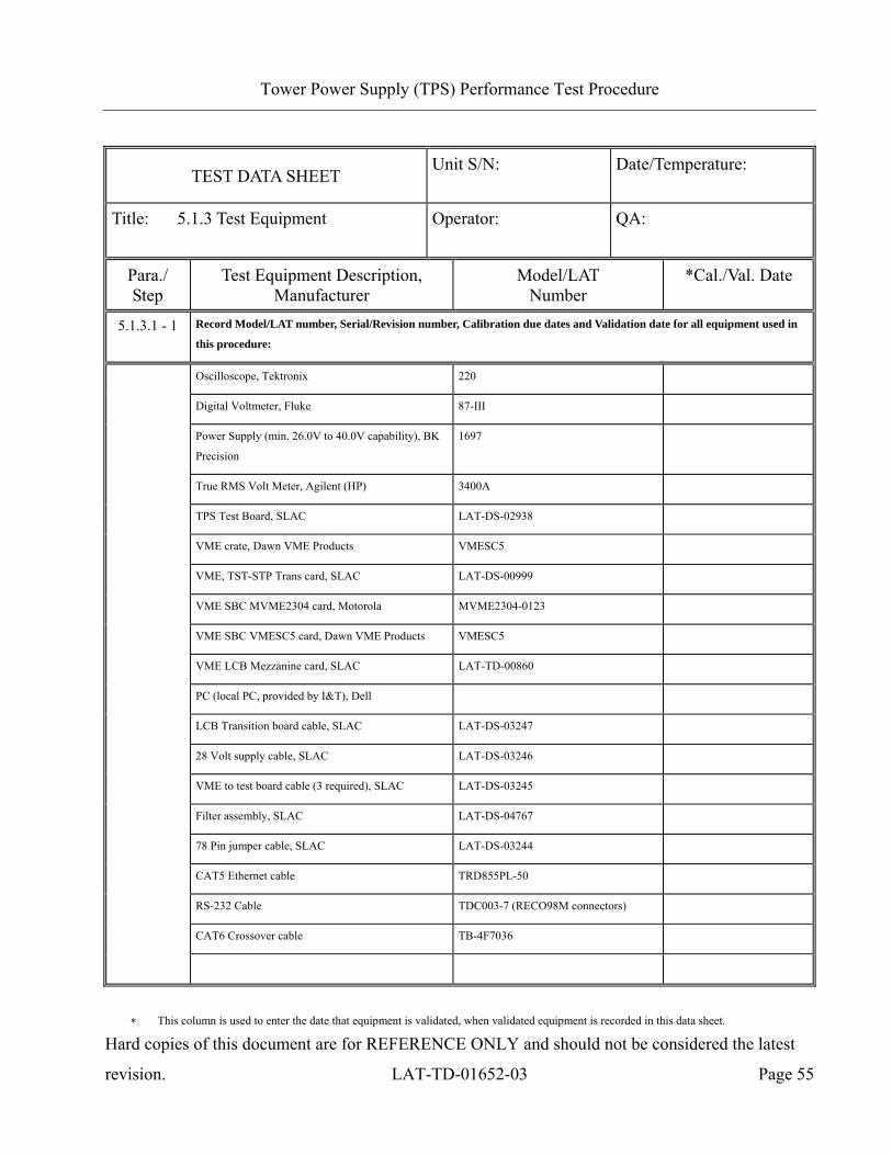
TEST DATA SHEET Unit S/N:
Date/Temperature:
Title: 5.1.3 Test Equipment Operator:
QA:
Para./ Step
Test Equipment Description, Manufacturer
Model/LAT Number
*Cal./Val. Date
5.1.3.1 - 1 Record Model/LAT number, Serial/Revision number, Calibration due dates and Validation date for all equipment used in
this procedure:
Oscilloscope, Tektronix 220
Digital Voltmeter, Fluke 87-III
Power Supply (min. 26.0V to 40.0V capability), BK
Precision
1697
True RMS Volt Meter, Agilent (HP) 3400A
TPS Test Board, SLAC LAT-DS-02938
VME crate, Dawn VME Products VMESC5
VME, TST-STP Trans card, SLAC LAT-DS-00999
VME SBC MVME2304 card, Motorola MVME2304-0123
VME SBC VMESC5 card, Dawn VME Products VMESC5
VME LCB Mezzanine card, SLAC LAT-TD-00860
PC (local PC, provided by I&T), Dell
LCB Transition board cable, SLAC LAT-DS-03247
28 Volt supply cable, SLAC LAT-DS-03246
VME to test board cable (3 required), SLAC LAT-DS-03245
Filter assembly, SLAC LAT-DS-04767
78 Pin jumper cable, SLAC LAT-DS-03244
CAT5 Ethernet cable TRD855PL-50
RS-232 Cable TDC003-7 (RECO98M connectors)
CAT6 Crossover cable TB-4F7036
∗ This column is used to enter the date that equipment is validated, when validated equipment is recorded in this data sheet.
Page 57
Tower Power Supply Assembly CPT/LPT Test Procedure
Hard copies of this document are for REFERENCE ONLY and should not be considered the latest
revision. LAT-TD-01652-03 Page 56
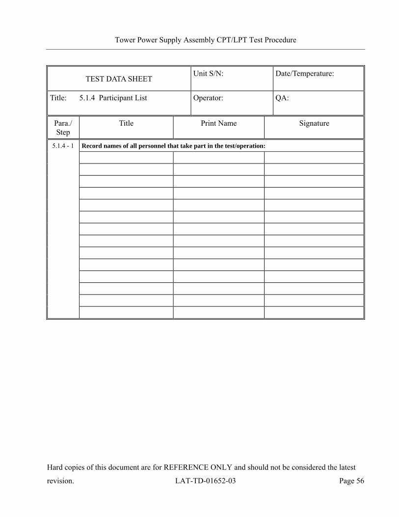
TEST DATA SHEET Unit S/N:
Date/Temperature:
Title: 5.1.4 Participant List Operator:
QA:
Para./ Step
Title Print Name Signature
Record names of all personnel that take part in the test/operation:
5.1.4 - 1
Page 58
Tower Power Supply Assembly CPT/LPT Test Procedure
Hard copies of this document are for REFERENCE ONLY and should not be considered the latest
revision. LAT-TD-01652-03 Page 57
TEST DATA SHEET Unit S/N:
Date:
Title: 5.2.1 Pre Operation Verifications Operator:
QA:
Para./ Step
Description Limits Unit Data
5.2 Pre-Operation Verifications -1 Notify QAE. OK OK/NG
-2 Test Readiness Review is done. OK OK/NG
Record the EUT equipment:
TEM Part number NA NA
TEM LAT Bay location NA NA
TEM Serial number NA NA
TPS Part number NA NA
TPS LAT Bay location NA NA
-3
TPS Serial number NA NA
-4 Power off the LAT or EGSE. OFF ON/OFF
-5 Set DMM to autoranging for resistance. OK OK/NG
-6 Measure DMM lead resistance. < 2.0 Ω
-7 Measure EUT to ground. < 2.0 Ω
-8 Measure equipment to ground. < 2.0 Ω
-9 All connector savers are installed on the flight connections. OK OK/NG
-10 The test equipment and participant lists have been completed. OK OK/NG
Page 59
Tower Power Supply Assembly CPT/LPT Test Procedure
Hard copies of this document are for REFERENCE ONLY and should not be considered the latest
revision. LAT-TD-01652-03 Page 58
TEST DATA SHEET Unit S/N: Date/Temperature:
Paragraph: 5.4 Subassembly Level Testing Operator: QA:
Step Description Requirement Units Data
Switching Test:
<400m peak to peak Volts 5.4.1-3 Verify that the information on the scope matches the sample, the signal
after the filter (TPS EUT) at the top of Q12 (+) and the TPS ground (-) 8 to 10µ Seconds
Page 60
Tower Power Supply Assembly CPT/LPT Test Procedure
Hard copies of this document are for REFERENCE ONLY and should not be considered the latest
revision. LAT-TD-01652-03 Page 59
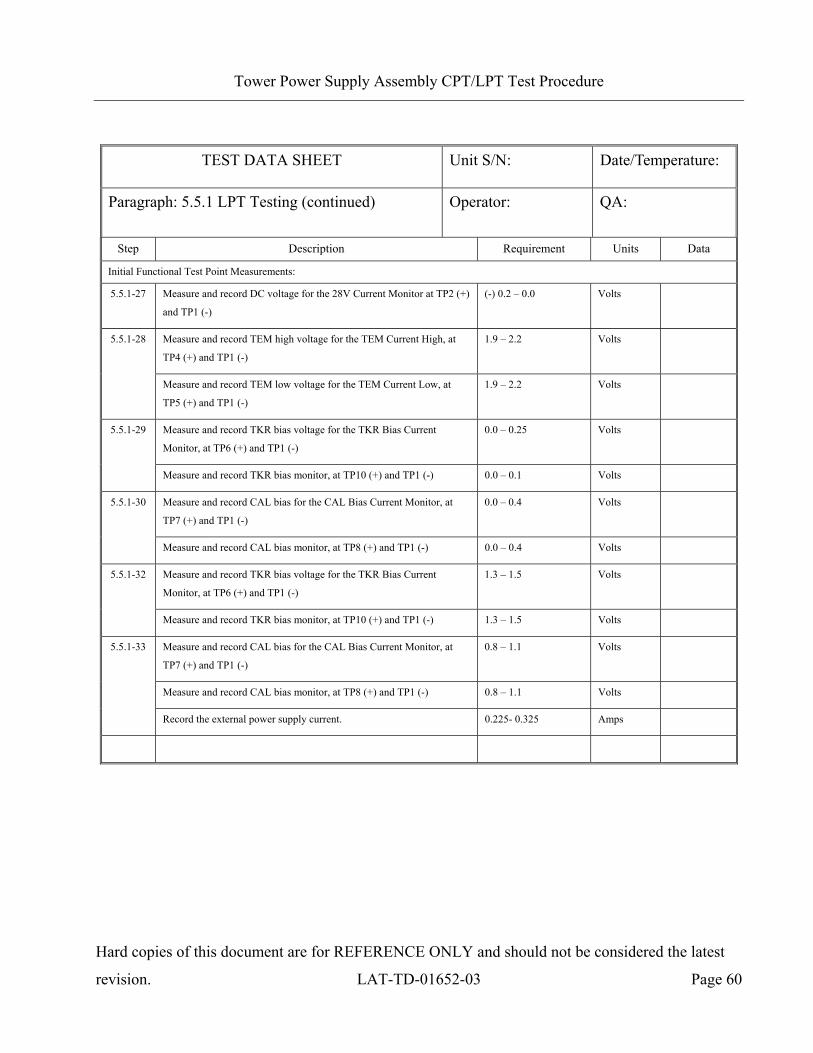
TEST DATA SHEET Unit S/N: Date/Temperature:
Paragraph: 5.5.1 LPT Testing Operator: QA:
Step Description Requirement Units Data
Functional Tests, LEDs Illuminated Verifications:
Verify that LED D2 is illuminated. OK OK/NG 5.5.1-16
Verify that LED D3 is illuminated. OK OK/NG
5.5.1-17 Record the external power supply current. 0.01 - 0.06 Amperage
Verify that LED D4 is illuminated. OK OK/NG
Verify that LED D10 is illuminated. OK OK/NG
5.5.1-19
Verify that LED D11 is illuminated. OK OK/NG
5.5.1-20 Record the external power supply current. 0.08 – 0.13 Amperage
Verify that LED D5 is illuminated. OK OK/NG 5.5.1-22
Verify that LED D6 is illuminated. OK OK/NG
5.5.1-23 Record the external power supply current. 0.16 – 0.21 Amperage
Verify that LED D7 is illuminated. OK OK/NG
Verify that LED D8 is illuminated. OK OK/NG
5.5.1-25
Verify that LED D9 is illuminated. OK OK/NG
5.5.1-26 Record the external power supply current. 0.225 – 0.325 Amperage
Page 61
Tower Power Supply Assembly CPT/LPT Test Procedure
Hard copies of this document are for REFERENCE ONLY and should not be considered the latest
revision. LAT-TD-01652-03 Page 60
TEST DATA SHEET Unit S/N: Date/Temperature:
Paragraph: 5.5.1 LPT Testing (continued) Operator: QA:
Step Description Requirement Units Data
Initial Functional Test Point Measurements:
5.5.1-27 Measure and record DC voltage for the 28V Current Monitor at TP2 (+)
and TP1 (-)
(-) 0.2 – 0.0 Volts
Measure and record TEM high voltage for the TEM Current High, at
TP4 (+) and TP1 (-)
1.9 – 2.2 Volts 5.5.1-28
Measure and record TEM low voltage for the TEM Current Low, at
TP5 (+) and TP1 (-)
1.9 – 2.2 Volts
Measure and record TKR bias voltage for the TKR Bias Current
Monitor, at TP6 (+) and TP1 (-)
0.0 – 0.25 Volts 5.5.1-29
Measure and record TKR bias monitor, at TP10 (+) and TP1 (-) 0.0 – 0.1 Volts
Measure and record CAL bias for the CAL Bias Current Monitor, at
TP7 (+) and TP1 (-)
0.0 – 0.4 Volts 5.5.1-30
Measure and record CAL bias monitor, at TP8 (+) and TP1 (-) 0.0 – 0.4 Volts
Measure and record TKR bias voltage for the TKR Bias Current
Monitor, at TP6 (+) and TP1 (-)
1.3 – 1.5 Volts 5.5.1-32
Measure and record TKR bias monitor, at TP10 (+) and TP1 (-) 1.3 – 1.5 Volts
Measure and record CAL bias for the CAL Bias Current Monitor, at
TP7 (+) and TP1 (-)
0.8 – 1.1 Volts
Measure and record CAL bias monitor, at TP8 (+) and TP1 (-) 0.8 – 1.1 Volts
5.5.1-33
Record the external power supply current. 0.225- 0.325 Amps
Page 62
Tower Power Supply Assembly CPT/LPT Test Procedure
Hard copies of this document are for REFERENCE ONLY and should not be considered the latest
revision. LAT-TD-01652-03 Page 61
TEST DATA SHEET Unit S/N: Date/Temperature:
Paragraph: 5.5.1 LPT Testing (continued) Operator: QA:
Step Description Requirement Units Data
Baseline Measurements:
Measure and record CAL Bias voltage, at TP9 (+) and TP1 (-) 80 - 100 Volts 5.5.1-34
Measure and record TKR Bias voltage, at TP11 (+) and TP1 (-) 125 – 155 Volts
Measure and record CAL 3.3 analog voltage, at TP12 (+) and TP1 (-) 3.2 – 3.465 Volts
Measure and record CAL 3.3 digital voltage, at TP13 (+) and TP1 (-) 3.2 – 3.465 Volts
Measure and record TKR 2.65 digital voltage, at TP14 (+) and TP1 (-) 2.50 – 2.80 Volts
Measure and record TKR 2.65 analog voltage, at TP15 (+) and TP1 (-) 2.50 – 2.80 Volts
Measure and record TKR 1.5 analog voltage, at TP16 (+) and TP1 (-) 1.55-1.75 Volts
Measure and record TEM 2.5 voltage, at TP17 (+) and TP1 (-) 2.4 – 2.625 Volts
5.5.1-35
Measure and record TEM 3.3 voltage, at TP18 (+) and TP1 (-) 3.2 – 3.465 Volts
Measure and record TEM V1 voltage, at TP19 (+) and TP1 (-) 3.1 – 3.36 Volts 5.5.1-36
Measure and record TEM V2 voltage, at TP20 (+) and TP1 (-) 3.1 – 3.36 Volts
Measure and record TEM T1 temperature, at TP26 (+) and TP1 (-) 1.5 – 1.7 Volts
Measure and record TEM T2 temperature, at TP27 (+) and TP1 (-) 1.5 – 1.7 Volts
Measure and record TEM PS T1 temperature, at TP28 (+) and TP1 (-) 1.3 – 1.9 Volts
5.5.1-37
Measure and record TEM PS T2 temperature, at TP29 (+) and TP1 (-) 1.3 – 1.9 Volts
Page 63
Tower Power Supply Assembly CPT/LPT Test Procedure
Hard copies of this document are for REFERENCE ONLY and should not be considered the latest
revision. LAT-TD-01652-03 Page 62
TEST DATA SHEET Unit S/N: Date/Temperature:
Paragraph: 5.5.1 LPT Testing (continued) Operator: QA:
Step Description Requirement Units Data
Ripple Voltage:
Measure and record AC ripple voltage, at TP3 (+) and TP1 (-) on scope < 60m peak to peak Volts 5.5.1-39
Measure and record the time, at TP3 (+) and TP1 (-) on scope 8 – 11 µ Seconds
Load Regulation, at 100% load:
Measure and record the 9 supply voltages and current at the external
power supply
NA NA NA
Measure and record CAL Bias voltage, at TP9 (+) and TP1 (-) 70 – 100 Volts
Calculate the delta between measurements (TP9 step 32 – TP9 step 38) 0.0 – 10.0 Volts
Measure and record TKR Bias voltage, at TP11 (+) and TP1 (-) 105 - 145 Volts
Calculate the delta between measurements (TP11 step 32 – TP11 step 38) 0.0 – 20.0 Volts
Measure and record CAL 3.3 analog voltage, at TP12 (+) and TP1 (-) 3.2 – 3.4 Volts
Calculate the delta between measurements (TP12 step 33 – TP12 step 38) 0.0 – 0.2 Volts
Measure and record CAL 3.3 digital voltage, at TP13 (+) and TP1 (-) 3.2 – 3.4 Volts
Calculate the delta between measurements (TP13 step 33 – TP13 step 38) 0.0 – 0.2 Volts
Measure and record TKR 2.65 digital voltage, at TP14 (+) and TP1 (-) 2.35 – 2.73 Volts
Calculate the delta between measurements (TP14 step 33 – TP14 step 38) 0.0 – 0.2 Volts
Measure and record TKR 2.65 analog voltage, at TP15 (+) and TP1 (-) 2.35 – 2.73 Volts
Calculate the delta between measurements (TP15 step 33 – TP15 step 38) 0.0 – 0.2 Volts
Measure and record TKR 1.5 analog voltage, at TP16 (+) and TP1 (-) 1.45-1.65 Volts
Calculate the delta between measurements (TP16 step 33 – TP16 step 38) 0.0 – 0.2 Volts
Measure and record TEM 2.5 voltage, at TP17 (+) and TP1 (-) 2.4 – 2.6 Volts
Calculate the delta between measurements (TP17 step 33 – TP17 step 38) 0.0 – 0.2 Volts
Measure and record TEM 3.3 voltage, at TP18 (+) and TP1 (-) 3.2 – 3.4 Volts
Calculate the delta between measurements (TP18 step 33 – TP18 step 38) 0.0 – 0.2 Volts
5.5.1-40
Record the external power supply current. 0.9 – 1.1 Amps
Page 64
Tower Power Supply Assembly CPT/LPT Test Procedure
Hard copies of this document are for REFERENCE ONLY and should not be considered the latest
revision. LAT-TD-01652-03 Page 63
TEST DATA SHEET Unit S/N: Date/Temperature:
Paragraph: 5.5.1 LPT Testing (continued) Operator: QA:
Step Description Requirement Units Data
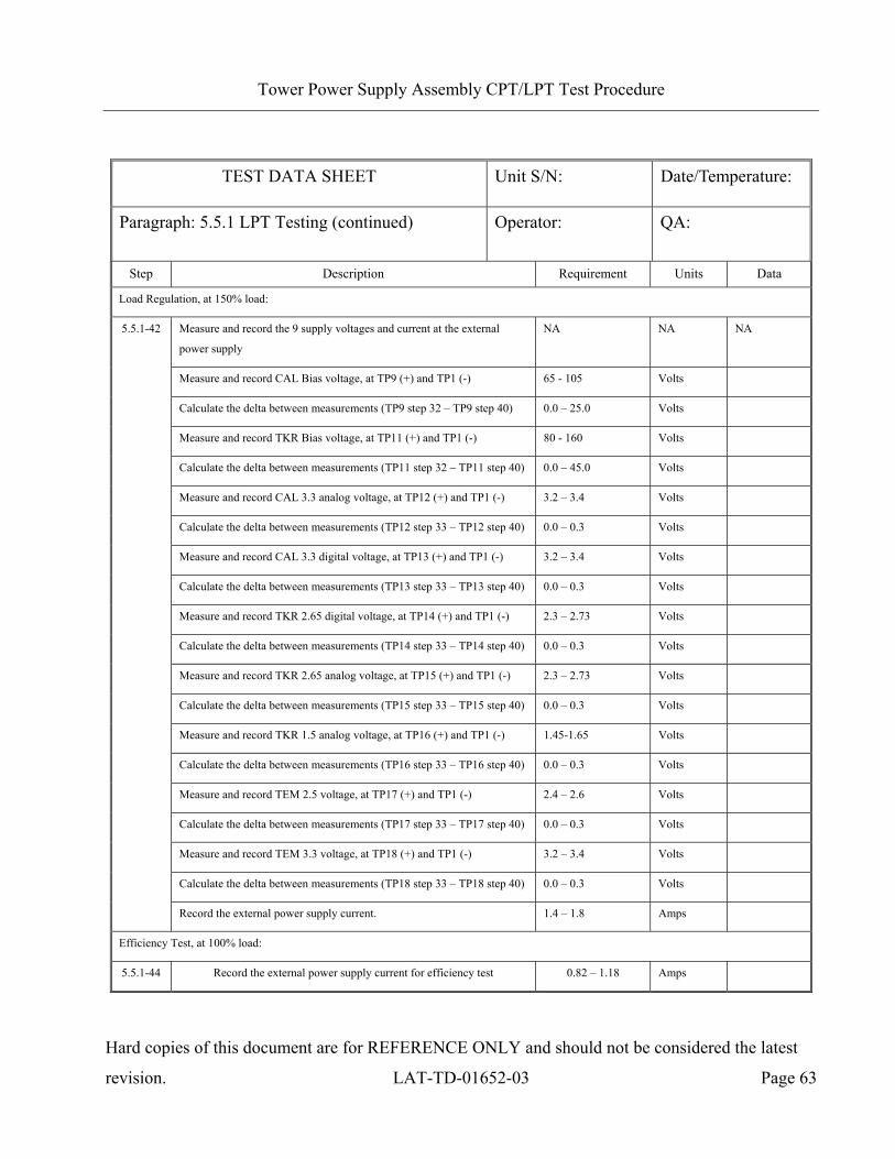
Load Regulation, at 150% load:
Measure and record the 9 supply voltages and current at the external
power supply
NA NA NA
Measure and record CAL Bias voltage, at TP9 (+) and TP1 (-) 65 - 105 Volts
Calculate the delta between measurements (TP9 step 32 – TP9 step 40) 0.0 – 25.0 Volts
Measure and record TKR Bias voltage, at TP11 (+) and TP1 (-) 80 - 160 Volts
Calculate the delta between measurements (TP11 step 32 – TP11 step 40) 0.0 – 45.0 Volts
Measure and record CAL 3.3 analog voltage, at TP12 (+) and TP1 (-) 3.2 – 3.4 Volts
Calculate the delta between measurements (TP12 step 33 – TP12 step 40) 0.0 – 0.3 Volts
Measure and record CAL 3.3 digital voltage, at TP13 (+) and TP1 (-) 3.2 – 3.4 Volts
Calculate the delta between measurements (TP13 step 33 – TP13 step 40) 0.0 – 0.3 Volts
Measure and record TKR 2.65 digital voltage, at TP14 (+) and TP1 (-) 2.3 – 2.73 Volts
Calculate the delta between measurements (TP14 step 33 – TP14 step 40) 0.0 – 0.3 Volts
Measure and record TKR 2.65 analog voltage, at TP15 (+) and TP1 (-) 2.3 – 2.73 Volts
Calculate the delta between measurements (TP15 step 33 – TP15 step 40) 0.0 – 0.3 Volts
Measure and record TKR 1.5 analog voltage, at TP16 (+) and TP1 (-) 1.45-1.65 Volts
Calculate the delta between measurements (TP16 step 33 – TP16 step 40) 0.0 – 0.3 Volts
Measure and record TEM 2.5 voltage, at TP17 (+) and TP1 (-) 2.4 – 2.6 Volts
Calculate the delta between measurements (TP17 step 33 – TP17 step 40) 0.0 – 0.3 Volts
Measure and record TEM 3.3 voltage, at TP18 (+) and TP1 (-) 3.2 – 3.4 Volts
Calculate the delta between measurements (TP18 step 33 – TP18 step 40) 0.0 – 0.3 Volts
5.5.1-42
Record the external power supply current. 1.4 – 1.8 Amps
Efficiency Test, at 100% load:
5.5.1-44 Record the external power supply current for efficiency test 0.82 – 1.18 Amps
Page 65
Tower Power Supply Assembly CPT/LPT Test Procedure
Hard copies of this document are for REFERENCE ONLY and should not be considered the latest
revision. LAT-TD-01652-03 Page 64
TEST DATA SHEET Unit S/N: Date/Temperature:
Paragraph: 5.5.2 CPT Testing Operator: QA:
Step Description Requirement Units Data
Line Regulation Test, at 100% load:
Measure and record the 9 supply voltages and current at the external
power supply (at 26.0V input voltage)
NA NA NA
Measure and record CAL Bias voltage, at TP9 (+) and TP1 (-) 70 – 100 Volts
Calculate the delta between measurements (TP9 step 32 – TP9 step 44) 0.0 – 10.0 Volts
Measure and record TKR Bias voltage, at TP11 (+) and TP1 (-) 105 - 145 Volts
Calculate the delta between measurements (TP11 step 32 – TP11 step 44) 0.0 – 20.0 Volts
Measure and record CAL 3.3 analog voltage, at TP12 (+) and TP1 (-) 3.2 – 3.4 Volts
Calculate the delta between measurements (TP12 step 33 – TP12 step 44) 0.0 – 0.2 Volts
Measure and record CAL 3.3 digital voltage, at TP13 (+) and TP1 (-) 3.2 – 3.4 Volts
Calculate the delta between measurements (TP13 step 33 – TP13 step 44) 0.0 – 0.2 Volts
Measure and record TKR 2.65 digital voltage, at TP14 (+) and TP1 (-) 2.35 – 2.73 Volts
Calculate the delta between measurements (TP14 step 33 – TP14 step 44) 0.0 – 0.2 Volts
Measure and record TKR 2.65 analog voltage, at TP15 (+) and TP1 (-) 2.35 – 2.73 Volts
Calculate the delta between measurements (TP15 step 33 – TP15 step 44) 0.0 – 0.2 Volts
Measure and record TKR 1.5 analog voltage, at TP16 (+) and TP1 (-) 1.3 – 1.6 Volts
Calculate the delta between measurements (TP16 step 33 – TP16 step 44) 0.0 – 0.2 Volts
Measure and record TEM 2.5 voltage, at TP17 (+) and TP1 (-) 2.4 – 2.6 Volts
Calculate the delta between measurements (TP17 step 33 – TP17 step 44) 0.0 – 0.2 Volts
Measure and record TEM 3.3 voltage, at TP18 (+) and TP1 (-) 3.2 – 3.4 Volts
Calculate the delta between measurements (TP18 step 33 – TP18 step 44) 0.0 – 0.2 Volts
5.5.2-2
Record the external power supply current. 0.82 – 1.18 Amps
Page 66
Tower Power Supply Assembly CPT/LPT Test Procedure
Hard copies of this document are for REFERENCE ONLY and should not be considered the latest
revision. LAT-TD-01652-03 Page 65
TEST DATA SHEET Unit S/N: Date/Temperature:
Paragraph: 5.5.2 CPT Testing (continued) Operator: QA:
Step Description Requirement Units Data
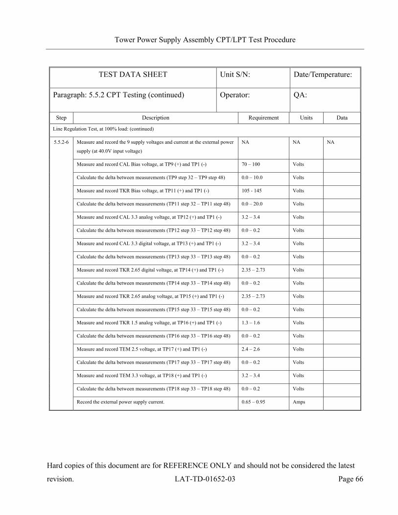
Line Regulation Test, at 100% load: (continued)
Measure and record the 9 supply voltages and current at the external power
supply (at 30.0V input voltage)
NA NA NA
Measure and record CAL Bias voltage, at TP9 (+) and TP1 (-) 70 – 100 Volts
Calculate the delta between measurements (TP9 step 32 – TP9 step 46) 0.0 – 10.0 Volts
Measure and record TKR Bias voltage, at TP11 (+) and TP1 (-) 105 - 145 Volts
Calculate the delta between measurements (TP11 step 32 – TP11 step 46) 0.0 – 20.0 Volts
Measure and record CAL 3.3 analog voltage, at TP12 (+) and TP1 (-) 3.2 – 3.4 Volts
Calculate the delta between measurements (TP12 step 33 – TP12 step 46) 0.0 – 0.2 Volts
Measure and record CAL 3.3 digital voltage, at TP13 (+) and TP1 (-) 3.2 – 3.4 Volts
Calculate the delta between measurements (TP13 step 33 – TP13 step 46) 0.0 – 0.2 Volts
Measure and record TKR 2.65 digital voltage, at TP14 (+) and TP1 (-) 2.35 – 2.73 Volts
Calculate the delta between measurements (TP14 step 33 – TP14 step 46) 0.0 – 0.2 Volts
Measure and record TKR 2.65 analog voltage, at TP15 (+) and TP1 (-) 2.35 – 2.73 Volts
Calculate the delta between measurements (TP15 step 33 – TP15 step 46) 0.0 – 0.2 Volts
Measure and record TKR 1.5 analog voltage, at TP16 (+) and TP1 (-) 1.3 – 1.6 Volts
Calculate the delta between measurements (TP16 step 33 – TP16 step 46) 0.0 – 0.2 Volts
Measure and record TEM 2.5 voltage, at TP17 (+) and TP1 (-) 2.4 – 2.6 Volts
Calculate the delta between measurements (TP17 step 33 – TP17 step 46) 0.0 – 0.2 Volts
Measure and record TEM 3.3 voltage, at TP18 (+) and TP1 (-) 3.2 – 3.4 Volts
Calculate the delta between measurements (TP18 step 33 – TP18 step 46) 0.0 – 0.2 Volts
5.5.2-4
Record the external power supply current. 0.82 – 1.18 Amps
Page 67
Tower Power Supply Assembly CPT/LPT Test Procedure
Hard copies of this document are for REFERENCE ONLY and should not be considered the latest
revision. LAT-TD-01652-03 Page 66
TEST DATA SHEET Unit S/N: Date/Temperature:
Paragraph: 5.5.2 CPT Testing (continued) Operator: QA:
Step Description Requirement Units Data
Line Regulation Test, at 100% load: (continued)
Measure and record the 9 supply voltages and current at the external power
supply (at 40.0V input voltage)
NA NA NA
Measure and record CAL Bias voltage, at TP9 (+) and TP1 (-) 70 – 100 Volts
Calculate the delta between measurements (TP9 step 32 – TP9 step 48) 0.0 – 10.0 Volts
Measure and record TKR Bias voltage, at TP11 (+) and TP1 (-) 105 - 145 Volts
Calculate the delta between measurements (TP11 step 32 – TP11 step 48) 0.0 – 20.0 Volts
Measure and record CAL 3.3 analog voltage, at TP12 (+) and TP1 (-) 3.2 – 3.4 Volts
Calculate the delta between measurements (TP12 step 33 – TP12 step 48) 0.0 – 0.2 Volts
Measure and record CAL 3.3 digital voltage, at TP13 (+) and TP1 (-) 3.2 – 3.4 Volts
Calculate the delta between measurements (TP13 step 33 – TP13 step 48) 0.0 – 0.2 Volts
Measure and record TKR 2.65 digital voltage, at TP14 (+) and TP1 (-) 2.35 – 2.73 Volts
Calculate the delta between measurements (TP14 step 33 – TP14 step 48) 0.0 – 0.2 Volts
Measure and record TKR 2.65 analog voltage, at TP15 (+) and TP1 (-) 2.35 – 2.73 Volts
Calculate the delta between measurements (TP15 step 33 – TP15 step 48) 0.0 – 0.2 Volts
Measure and record TKR 1.5 analog voltage, at TP16 (+) and TP1 (-) 1.3 – 1.6 Volts
Calculate the delta between measurements (TP16 step 33 – TP16 step 48) 0.0 – 0.2 Volts
Measure and record TEM 2.5 voltage, at TP17 (+) and TP1 (-) 2.4 – 2.6 Volts
Calculate the delta between measurements (TP17 step 33 – TP17 step 48) 0.0 – 0.2 Volts
Measure and record TEM 3.3 voltage, at TP18 (+) and TP1 (-) 3.2 – 3.4 Volts
Calculate the delta between measurements (TP18 step 33 – TP18 step 48) 0.0 – 0.2 Volts
5.5.2-6
Record the external power supply current. 0.65 – 0.95 Amps
Page 68
Tower Power Supply Assembly CPT/LPT Test Procedure
Hard copies of this document are for REFERENCE ONLY and should not be considered the latest
revision. LAT-TD-01652-03 Page 67
TEST DATA SHEET Unit S/N: Date/Temperature:
Paragraph: 5.5.2 CPT Testing (continued) Operator: QA:
Step Description Requirement Units Data
Margin Test, at 100% load:
Note: Do not run the margin tests for Flight unit testing.
Measure and record CAL 3.3 analog voltage, at TP12 (+) and TP1 (-) 2.7 – 3.0 Volts
Measure and record CAL 3.3 digital voltage, at TP13 (+) and TP1 (-) 2.7 – 3.0 Volts
Measure and record TKR 2.65 digital voltage, at TP14 (+) and TP1 (-) 1.9 – 2.3 Volts
Measure and record TKR 2.65 analog voltage, at TP15 (+) and TP1 (-) 1.9 – 2.3 Volts
Measure and record TKR 1.5 analog voltage, at TP16 (+) and TP1 (-) 1.0 – 1.35 Volts
Measure and record TEM 2.5 voltage, at TP17 (+) and TP1 (-) 1.9 – 2.3 Volts
5.5.2-10
Measure and record TEM 3.3 voltage, at TP18 (+) and TP1 (-) 2.7 – 3.0 Volts
Measure and record CAL 3.3 analog voltage, at TP12 (+) and TP1 (-) 3.6 – 4.0 Volts
Measure and record CAL 3.3 digital voltage, at TP13 (+) and TP1 (-) 3.6 – 4.0 Volts
Measure and record TKR 2.65 digital voltage, at TP14 (+) and TP1 (-) 2.85 – 3.1 Volts
Measure and record TKR 2.65 analog voltage, at TP15 (+) and TP1 (-) 2.85 – 3.1 Volts
Measure and record TKR 1.5 analog voltage, at TP16 (+) and TP1 (-) 1.6 – 1.8 Volts
Measure and record TEM 2.5 voltage, at TP17 (+) and TP1 (-) 2.7 – 2.9 Volts
5.5.2-12
Measure and record TEM 3.3 voltage, at TP18 (+) and TP1 (-) 3.6 – 4.0 Volts
Page 69
Tower Power Supply Assembly CPT/LPT Test Procedure
Hard copies of this document are for REFERENCE ONLY and should not be considered the latest
revision. LAT-TD-01652-03 Page 68
TEST DATA SHEET Unit S/N: Date/Temperature:
Paragraph: 5.5.2 CPT Testing (continued) Operator: QA:
Step Description Requirement Units Data
Load Response Transient Test, oscillator on:
NOTE: For the Digital and analog tests, use the EM sample for the EM unit and the Flight sample for the Flight unit.
5.5.2-17 Verify that the information on the scope matches the Bias sample, CAL
Bias, scope connection CH1 at TP9 (+) and TP1 (-)
<10 peak to peak Volts
5.5.2-18 Verify that the information on the scope matches the Bias sample, TKR
Bias, scope connection CH1 at TP11 (+) and TP1 (-)
<25 peak to peak Volts
Verify that the information on the scope matches the analog sample, CAL
3.3 analog voltage, scope connection CH1 at TP12 (+) and TP1 (-)
<400m peak to peak Volts 5.5.2-19
Verify the signal settles for the required period 2.50 –8.00 ms
Verify that the information on the scope matches the digital sample, CAL
3.3 digital voltage, scope connection CH1 at TP13 (+) and TP1 (-)
<700m peak to peak Volts 5.5.2-20
Verify the signal settles for the required period 2.50 –8.00 ms
Verify that the information on the scope matches the digital sample, TKR
2.65 digital voltage, scope connection CH1 at TP14 (+) and TP1 (-)
<1.75 peak to peak Volts 5.5.2-21
Verify the signal settles for the required period 2.50 –8.00 ms
Verify that the information on the scope matches the analog sample, TKR
2.65 analog voltage, scope connection CH1 at TP15 (+) and TP1 (-)
<700m peak to peak Volts 5.5.2-22
Verify the signal settles for the required period 2.50 –8.00 ms
Verify that the information on the scope matches the analog sample, TKR
1.5 analog voltage, scope connection CH1 at TP16 (+) and TP1 (-)
<1.5 peak to peak Volts 5.5.2-23
Verify the signal settles for the required period 2.50 –8.00 ms
Verify that the information on the scope matches the digital sample, TEM
2.5 voltage, at scope connection CH1 TP17 (+) and TP1 (-)
<100m peak to peak Volts 5.5.2-24
Verify the signal settles for the required period <1 ms
Verify that the information on the scope matches the digital sample, TEM
3.3 voltage, scope connection CH1 at TP18 (+) and TP1 (-)
<150m peak to peak Volts 5.5.2-25
Verify the signal settles for the required period <1 ms
Page 70
Tower Power Supply Assembly CPT/LPT Test Procedure
Hard copies of this document are for REFERENCE ONLY and should not be considered the latest
revision. LAT-TD-01652-03 Page 69
TEST DATA SHEET Unit S/N: Date/Temperature:
Paragraph: 5.5.2 CPT Testing (continued) Operator: QA:
Step Description Requirement Units Data
TPS Noise Test, at 100% load:
Measure and record CAL Bias voltage, at TP9 (+) and TP1 (-) <500µ Volts
Measure and record TKR Bias voltage, at TP11 (+) and TP1 (-) <500µ Volts
Measure and record CAL 3.3 analog voltage, at TP12 (+) and TP1 (-) <150µ Volts
Measure and record CAL 3.3 digital voltage, at TP13 (+) and TP1 (-) <200µ Volts
Measure and record TKR 2.65 digital voltage, at TP14 (+) and TP1 (-) <150µ Volts
Measure and record TKR 2.65 analog voltage, at TP15 (+) and TP1 (-) <150µ Volts
Measure and record TKR 1.5 analog voltage, at TP16 (+) and TP1 (-) <150µ Volts
Measure and record TEM 2.5 voltage, at TP17 (+) and TP1 (-) <500µ Volts
5.5.2-28
Measure and record TEM 3.3 voltage, at TP18 (+) and TP1 (-) <500µ Volts