35
Z2I-BS-TN-1-0316-R2 Launch Vehicle Payload User’s Guide January 2018 / Revision 2 Bloostar is the dedicated satellite launcher of Zero 2 Infinity

Z2I-BS-TN-1-0316-R2
Launch Vehicle Payload User’s Guide January 2018 / Revision 2
Bloostar is the dedicated satellite launcher of Zero 2 Infinity

Z2I-BS-TN-1-0316-R2
REVISION HISTORY Version Date By Description 0 March 2016 ASh First edition of the document for external
export Revision 1 June 2016 DB Global revision of the document. Revision 2 January 2018 IPM Table 1 Updates

Z2I-BS-TN-1-0316-R2
TABLE OF CONTENTS
REVISION HISTORY i
TABLE OF CONTENTS ii
LIST OF FIGURES iv
LIST OF TABLES v
LIST OF ACRONYMS v
1 INTRODUCTION 1 1.1 Company Description 1 1.2 Bloostar Program 1
1.2.1 Overview 1 1.2.2 Customer Relation 2 1.2.3 Development Roadmap 2
1.3 Advantages of a stratospheric release 5 1.4 Key Customer Advantages 6
2 BLOOSTAR VEHICLE OVERVIEW 7 2.1 Configuration 7 2.2 Structure and Mechanisms 9 2.3 Avionics 9
2.3.1 Guidance, Navigation and Control 10 2.3.2 Communication 11
2.4 Propulsion 11 2.4.1 Rocket engines 12 2.4.2 Propellant tanks 13 2.4.3 Propellant Feed System 14
2.5 Balloon Segment 15 2.5.1 High-altitude Balloon 15 2.5.2 Flight Train 15 2.5.3 Gondola 16
2.6 Sea Launch 16
3 BLOOSTAR TRAJECTORY AND PERFORMANCE 18 3.1 Flight Profile 18 3.2 Performance Capability 20 3.3 Payload Insertion Accuracy 20 3.4 Reliability: Anomaly Response 20
3.4.1 Engine ignition delay 21 3.4.2 Engine out capability 21

Z2I-BS-TN-1-0316-R2
4 PAYLOAD ACCOMMODATION 22 4.1 Fairing Volume 22 4.2 Mechanical Interfaces 22 4.3 Electrical Interfaces 23 4.4 Payload Requirements 23
4.4.1 Documentation 23 4.4.2 Loads 23 4.4.3 Configuration 23 4.4.4 Power, EMC and grounding 24 4.4.5 Hazardous propellants, Pyros and Pressurized systems 24 4.4.6 Safety 24
5 PAYLOAD ENVIRONMENTS 25 5.1 Ship environment 25 5.2 Mechanical 26
5.2.1 Quasi-Static Loads 26 5.2.2 Dynamic environment 26 5.2.3 Shock Environment 27 5.2.4 Acoustic Environment 27 5.2.5 Random vibration 27
5.3 Thermal, Atmospheric and Cleanliness 28 5.4 RF and EMC 28
6 LAUNCH CAMPAIGN 29 6.1 Typical Mission Timeline 29 6.2 Facilities 29 6.3 Additional Services 30 6.4 Post Launch Deliverables 30

Z2I-BS-TN-1-0316-R2
LIST OF FIGURES Figure 1: Stratospheric flight test of a multilayer flexible tank at 27km altitude 4
Figure 2: Static test of an early engine prototype 4
Figure 3: ASTOS plots of Drag vs. Altitude (left graph) and Heat Flux vs. Time (right graph) for a generic launcher ignited from ground (red) and from 20 km (blue). 5
Figure 4: Bloostar dimensions [mm] 8
Figure 5: Exploded view of the Bloostar launch vehicle 8
Figure 6: Overview of Propellant Feed System 14
Figure 7: Balloon gondola configuration 16
Figure 8: Flight cycle of Bloostar 19
Figure 9: Simulation of Altitude and Inertial Speed over Flight time 19
Figure 10: Bloostar performance for circular orbits from the Canary Islands 20
Figure 11: Bottom view of tolerable engine out capability - stage 1 and 2 can have one engine out each (marked red), plus their opposing pair 21
Figure 12: Bloostar fairing available inner dimensions 22
Figure 13: Quasi-Static Loads 26
Figure 14: Bloostar shock response spectrum 27

Z2I-BS-TN-1-0316-R2
LIST OF TABLES Table 1: Bloostar mass budget, excluding the 75kg payload 9
Table 2: Bloostar propulsion characteristics 13
Table 3: Orbital Insertion Accuracy (1 sigma) 20
Table 4: Summary of environmental conditions at various flight events 25
LIST OF ACRONYMS PUG Payload User Guide LEO Low Earth Orbit Z2I Zero 2 Infinity ESA European Space Agency GNC Guidance, Navigation and Control TVC Thrust Vector Control RCS Reaction Control System LOX Liquid Oxygen LCH4 Liquid Methane MLI Multi-Layer Insulation GNSS Global Navigation Satellite System RPM Rounds Per Minute RAAN Right Ascension of Ascending Node RF Radio Frequency ICD Interface Control Document CoG Center of Gravity EMC Electro-Magnetic Capability MPE Maximum Predicted Environment QSL Quasi Static Load SRS Shock Response Spectrum TLEs Two Line Elements

Z2I-BS-TN-1-0316-R2
1 INTRODUCTION The team at Zero 2 Infinity is pleased to present Bloostar Payload User’s Guide. This Payload User’s Guide (PUG) provides basic information about Bloostar launch vehicle, designed by Zero 2 Infinity to put a single, or a constellation of, micro and nanosatellites into Low Earth Orbit (LEO). This early version of the PUG is intended to introduce Bloostar to the customer. As the development program matures, the PUG’s focus will be shifted towards the interfaces, environments and operations related to launching the payload.
1.1 Company Description Zero 2 Infinity (Z2I) was founded in 2009 with one mission, to ease access to Space. Initially developing a capability to raise heavy payloads to near-space with stratospheric balloons, Z2I has used this know-how as the basis for the Bloostar launcher. Bloostar is a dedicated nano and microsatellite stratospheric launching system. Z2I is a purveyor of elevation to near-space and beyond, enabling the growth of new markets and applications with a truly commercial approach. All this is done in a sustainable way through the use of non-polluting stratospheric balloons. Z2I was founded by José Mariano López-Urdiales, an aeronautical engineer from the Universidad Politécnica de Madrid and a Master of Science in Space Propulsion graduate from Massachusetts Institute of Technology. “zero” stands for zero emissions as environmental values are fundamental to the company, while “infinity” evokes the vision to take customers and their products beyond the edge of the blue skies.
1.2 Bloostar Program 1.2.1 Overview There is a clear emergence in small satellites (<200 kg) – in a period of a single year, the four-year forecast of satellite launches was increased by 400%. The upsurge in performance of microsatellites has set the conditions for a disruption in the Space industry. With better performance and lower costs, microsatellites will open Space to a wider range of institutions, empowering them to provide better solutions for our knowledge-based societies. For this to occur, the fundamental tool that will allow microsatellites perform at their full potential is a dedicated microsatellite launcher.

Z2I-BS-TN-1-0316-R2 With Bloostar, we are simplifying access to Space so that more problems can efficiently be solved from Space. By means of a hybrid Balloon-Rocket solution (a “Rockoon”), Bloostar uses a stratospheric balloon as the initial ascent stage followed by three rocket stages to reach orbit. The balloon stage, launched from open seas on board a standard ship, eliminates the need for a launch facility and delivers the rocket stage to a near-space environment which enables significant advantages (see chapter 1.3). Bloostar thus leverages the atmosphere and gravity (through buoyancy) and becomes an elegantly efficient solution to affordable and responsive Space transportation for micro and nano class payloads. 1.2.2 Customer Relation Each customer will be closely working with a Z2I Mission Manager in order to facilitate the communication between both parties. The Mission Manager coordinates the entire mission; he/she is responsible for mission integration analysis, documentation deliverables, planning integration meetings/reports and coordinating all integration and test activities associated with the mission. The Mission Manager also interfaces with the technical staff and all associated licensing agencies in order to ensure a successful mission. The Mission Manager will also constantly provide information to the customer during the launch campaign to allow a personal insight and to ensure their satisfaction. For queries about the Bloostar program, contractual or technical, any potential customer is welcome to contact us at [email protected]. 1.2.3 Development Roadmap Bloostar development program has already begun and is based on an iterative design-build-test approach – a philosophy in which all Zero 2 Infinity projects rely on. The project incorporates the most advanced technologies in rapid prototyping like 3D printing to ensure fast iteration and improvement cycles. All new systems will undergo a rigorous testing program, with opportunities for gradually scaled up performance and operations.
● PHASE 1: High-altitude subsystem tests – This phase has already started and includes continued testing of key subsystems and operational procedures, while the technical design is finalized in parallel.
● PHASE 2: Nanobloostar – This phase will cover the development of a Balloon-Launched single-stage suborbital launcher with the ability to carry out a precise suborbital flight with a 75 kg payload to 180 km altitude. The suborbital launcher will be identical to the third stage of the subsequent orbital launcher. The timeline for this phase is estimated to 1

Z2I-BS-TN-1-0316-R2
year. ● PHASE 3: Bloostar – After a second round of investment, the
development continues with the full 3-stage launcher with capacity to insert 75 kg into a polar 600 km orbit. The third stage will be re-used from the above suborbital launcher. The other stages share key commonalities that are slightly upgraded such as pressurization system, tanks configuration, avionics and launch operations.
Based on Zero 2 Infinity's existing and proven capabilities of launching heavy high altitude balloons, the rocket segment can with each design iteration be repeatedly tested under its actual flight conditions (unlike ground-launched solutions, or even aircraft-released solutions that have not yet completed their airplane segment). This would validate key technologies for the orbital launcher in terms of rocket engine capability, tank performance, avionics behaviour, guidance procedures and ground control. Current status of the Bloostar program:
● The first stage of the launch, the capability of launching heavy payloads to near-space, is fully developed and mastered.
● Completed stratospheric flight test of flexible tank prototype (Figure 1) ● Completed ground firing of first rocket engine prototype (Figure 2) ● Full configuration and operation design ● Analysis and simulations already complete ● Successful selection of providers and materials
One of the first key technical milestones carried out by Zero 2 Infinity was the flight test of an inflatable flexible multilayer tank, which was ascended smoothly to 27 km altitude. The key objective of the flight was to test the behaviour, strength and suitability of an inflatable pressurized tank envisioned in the Bloostar design. The tank performed flawlessly during the flight and confirmed the superior specific performance and resistance of inflatable structures.

Z2I-BS-TN-1-0316-R2
Figure 1: Stratospheric flight test of a multilayer flexible tank at 27km altitude
In the ongoing engine development process, an early engine prototype has been designed, built and successfully tested. The acquired knowledge has been implemented in the design of the next, more powerful, iteration. It is estimated to reach full scale engine firings within a year.
Figure 2: Static test of an early engine prototype
1.3 Advantages of a stratospheric release

Z2I-BS-TN-1-0316-R2 Launching a rocket above 99% of the mass of the atmosphere, where the aerodynamic resistance is near-negligible, yields several significant advantages compared to a standard ground-based launch. Extensive mission analysis with the ASTOS software tool (used by e.g. ESA in launcher designs), comparing Bloostar and a ground-ignited equivalent, shows a ~8% deltaV decrease required for Bloostar to reach orbit. This improvement originates from lower drag losses, lower gravity losses and nozzles working at optimum performance. What seems like a small improvement in deltaV results in a significant payload increase due to the exponential relation between vehicle weight and deltaV (Tsiolkowsky equation). As seen in Figure 3 (left), drag can be 20 times less when the launcher is ignited from the stratosphere compared to igniting form ground.
Figure 3: ASTOS plots of Drag vs. Altitude (left graph) and Heat Flux vs. Time (right
graph) for a generic launcher ignited from ground (red) and from 20 km (blue). It should be noted that lower atmospheric density has more benefits than solely decreased deltaV. It also influences the vibrations the payload needs to withstand and the weight of the launcher structure because of reduced load cases. Figure 3 (right) shows that also the thermal heat flux is reduced by a factor of 10. This implies even further significant mass savings because of the decreased thermal insulation the vehicle needs to carry and the early separation of the fairing. On the propulsion side, the low chamber pressure experienced in near-space makes feasible the utilization of pressure fed systems while not requiring thick/heavy tank structures. This significantly decreases mass and complexity of

Z2I-BS-TN-1-0316-R2 the vehicle reducing development and operating costs. Pressure fed systems in term allow the use of Differential Throttling for trajectory control, eliminating the need for Thrust Vector Control gimbals on some engines. On the ground segment side, additional cost can be saved by using the remaining balloon segment as a high altitude communication relay after the rocket has been release and ignited. This thus eliminates the need for costly ground stations along the initial flight path. All these factors combined reveal the true advantage of launching from the stratosphere. And in the long run, such simplified rocket configurations that only a near-space launch allows, will be the easiest to make reusable - further reducing the cost and increasing the rates of launch to satisfy the growing demand for constellations.
1.4 Key Customer Advantages The gains listed in the previous chapter translate into the following unique advantages for the customer compared to other launch vehicles:
● Cheapest dedicated nanosat launcher on the market ● Availability: less risk of launch delay due to bad weather (wind is
compensated by the ship’s aligned course) ● Most benign vibrational and shock environment
o Use of lighter spacecraft structure o Less need for costly and time consuming launch qualification tests
● Double payload volume ● ITAR-free launch ● Possibility to launch from different places around the world

Z2I-BS-TN-1-0316-R2
2 BLOOSTAR VEHICLE OVERVIEW Bloostar is a dedicated nano and microsatellite launching system that will put payloads of 75kg into a 600km Sun-Synchronous Orbit. It is based on the Rockoon method: an orbital launcher which is ignited from a balloon platform in near-space at an altitude of 20km (65,000ft). The Rockoon method efficiently substitutes the first stage of a conventional rocket with a Helium balloon ascent in order to avoid flying through the denser parts of the atmosphere at high velocities. This approach opens up a world of benefits unique for a Rockoon, described in detail in chapter 1.3. Having already mastered stratospheric balloon missions, the next natural step for Z2I is to build upon this expertize and develop the Bloostar launch vehicle. It is designed with simplicity in mind to ensure lower development and operational costs.
2.1 Configuration The rocket segment of the vehicle consists of three toroidal stages arranged concentrically as seen in Figure 4 and Figure 5. The first stage wraps around the second stage with a torus-shaped structural tank. Similarly, the second stage tank wraps around the third and final stage. Several structural rings around each toroidal tank acts as fixture points for engines and other subsystems. The compact toroidal shape of Bloostar makes the launcher more controllable and easier to integrate (no need for erection systems or towers).

Z2I-BS-TN-1-0316-R2
Figure 4: Bloostar dimensions [mm]
Figure 5: Exploded view of the Bloostar launch vehicle
The payload will be located in the center of the launcher on top (attached to the third stage). The geometry of the system takes advantage of the fact that the vehicle is launched from near-space where the aerodynamic resistance is near-negligible. The rocket segment of the Bloostar vehicle has a total mass of 4.9 metric tons, a mass breakdown is listed in Table 1.

Z2I-BS-TN-1-0316-R2
Component 1st stage 2nd stage 3rd stage Total Inert mass (kg) 561 97 80 739 Propellant mass (kg) 3397 604 320 4321 Total stage mass (kg) 3958 701 400 5135
Table 1: Bloostar mass budget, excluding the 75kg payload
2.2 Structure and Mechanisms The structure of Bloostar’s stages consists mainly of the tanks, who fulfill a structural function as well as storing the propellants. The engines, avionics, communication and power units will be attached to hardpoints on the tanks. The engines are additionally connected through dedicated engine mounts and struts. Traditional fairings need to withstand significant structural and acoustic loads. This is not the case for Bloostar, which can carry a much lighter fairing. The purpose of Bloostar’s fairing is to keep the payload protected during the balloon ascent and to prevent damage of the sensitive parts of the payload because of the (limited) aero heating from the first phase of the rocket propelled flight. For this purpose, a flexible, retractable fairing, with rigid carbon fiber ribs and a multilayer canvas of betacloth (Teflon-coated fiberglass), has been designed. A gas barrier layer is included as the innermost layer. Bloostar’s stage separation is performed by synchronized pyro devices. These units are reliable but expensive and produce some shock. The long term goal is to switch to low-shock mechanisms found in the military aircraft sector.
2.3 Avionics The Avionics system is responsible for sensing the motion of the launcher, running the GNC software, controlling actuators, monitoring each subsystem’s state, communicating with ground and supplying electrical power. Much of these systems are based on our existing flight-proven and robust Avionics set, with added features to be qualified under stratospheric and suborbital flights as a part of the Bloostar development program. 2.3.1 Guidance, Navigation and Control The Guidance, Navigation and Control (GNC) system calculates the optimum trajectory and controls the elements for modifying the trajectory. It uses a set of redundant sensors (3-axis gyros, accelerometers, ambient pressure gauges,

Z2I-BS-TN-1-0316-R2 GPS, Sun sensors etc.) and redundant flight computers. The trajectory is controlled using Thrust Vector Control and Engine Throttling methods described in the below subchapters. The compact configuration of Bloostar makes control much simpler than the very slender bodies of traditional launch vehicles. Figure 4 shows the definition of the axes for the Bloostar launch vehicle, where the X axis is the roll axis, and therefore the vertical axis for any vertically mounted payload. 2.3.1.1 Thrust Vector Control Each engine will be equipped with a set of Thrust Vector Control (TVC) actuators. Due to the many engines, the TVC system mass will be a significant part of the dry mass. It is therefore necessary to use low mass units such as Electro Mechanical Actuators. A range of commercially available units exist that fulfil the requirements for performance and reliability. The first and second stage TVC’s can provide torques around the x, y and z axis, but the third stage, equipped with a single rocket engine, can only produce torques about the y and z axes. For the x axis (roll) of stage 3, a simple Reaction Control System (RCS) is implemented using excess Helium pressurant gas. 2.3.1.2 Future improvements: Differential Throttling The baseline method for controlling Bloostar’s trajectory is using TVC, but future improved versions may progressively switch some engines to Differential Throttling. The toroidal shape of Bloostar, the symmetrically spaced engines and the pressure-fed system allows for this simpler control method which have typically only been used on small Unmanned Air Vehicles such as quad-rotors. As the radius of Bloostar is significantly larger than its height, it is possible to use Differential Throttling of the rocket engines to produce the required torques in a similar fashion to that employed by quad-rotors. Z2I have conducted a research project to investigate the suitability of Differential Throttling versus TVC. In order to compare the two control systems, a model of Bloostar was produced in MatLab/Simulink and a series of simulations was conducted, testing the control systems in various flight phases. We found that if the throttle response rate of the engines was fast enough, the Differential Throttling controller performed better than a TVC system. The throttling itself can be achieved by a simple propellant flow regulation. As the propellant is pressure-fed into the engines this can be easily achieved using fast variable-amplitude valves. Consequently, the conclusion was that using such a propellant feed system and regulation allows the thrust level to be adjusted

Z2I-BS-TN-1-0316-R2 quickly enough to maintain sufficient control of the vehicle – while saving on mass, cost and overall vehicle complexity. 2.3.2 Communication Communication between ground and the launcher is crucial throughout the entire flight, both with the balloon segment and rocket segment. Bloostar is designed to provide a two-way link for real-time flight data (telemetry) and ground safety commands (telecommand). Moreover, off-line data is provided for post-mission processing and diagnostics. A redundant C-band communications system, already flight-qualified in previous stratospheric flights, is envisaged for Bloostar.
2.4 Propulsion Bloostar is powered by liquid oxygen (LOX) and liquid methane (LCH4). This bi-propellant combination is the perfect match between performance, simplicity of combustion and green propulsion. The engines are optimized to work efficiently in the very low pressure environment where ignition takes place; between 20 and 25km. Bloostar’s first stage contains 6 engines with a vacuum thrust of 15 kN. The second stage has another 6 engines with 2 kN of vacuum thrust. The third stage’s single engine is identical to the ones used in the second stage (2kN). All 13 engines are ignited upon launch from the balloon platform, resulting in a total thrust of 104 kN. Table 2 gives specific data about the engines and propulsion of each stage. The Propulsion system utilized cross-tanking. This function optimizes the capabilities of every stage by allowing each tank to be full of propellants when the previous stage is detached. It also saves dry mass since all engines can be ignited during the whole trajectory. 2.4.1 Rocket engines Simplicity and robustness is the key driver for our engine development. The two different types of engines used are designed with high structural margin and redundant ignition systems. Because the launcher operates in a low-pressure to vacuum environment (near-space to Space), the engine nozzle can be optimized for maximum performance in a single pressure environment (that of vacuum). The engine size allows for 3D printing manufacturing techniques, easing the rapid prototyping-test-improvement cycle. Ceramic thermal protection can be

Z2I-BS-TN-1-0316-R2 deposited on parts of the chamber through thermal spray. The injector plate is a classical co-axial system and the thrust chamber is regeneratively cooled with methane.

Z2I-BS-TN-1-0316-R2 1st stage 2nd stage 3rd stage Number of engines 6 6 1 Propellant LOX/LCH4 LOX/LCH4 LOX/LCH4 Chamber pressure (bar) 10 10 10 Chamber thrust vacuum (kN) 15 2 2
Specific impulse vacuum (s) 345 355 355
Total mass flow rate (kg/s) 4.40 0.57 0.57
Contraction area ratio 5 7 7 Expansion area ratio 60 80 80 Propellant feed system Pressure Pressure Pressure Tank pressurization Helium Helium Helium Cooling method Regenerative Regenerative Regenerative Delta-V (km/s) 3.6 2.7 2.7 Tank type Linerless cryogenic Linerless cryogenic Linerless cryogenic
Table 2: Bloostar propulsion characteristics 2.4.2 Propellant tanks The first and second stage’s toroidal volume are composed mostly by toroidal carbon fiber filament wound tanks. They are kept at pressure and provide structural rigidity to the rocket. They are made in one piece by filament winding, and they are equipped with an internal liner to avoid micro-cracking in the composite walls. T1000G fibers provide the right strength to weight ratio for this application. Internal baffles have been added to prevent low frequency sloshing modes. Several axial reinforcements made by hand lay-up will be placed at the attachment points between the stages, tanks and fairing. For the third stage, where every kg saved in dry mass is a kg of payload, an even more optimized solution has been adopted; flexible multilayer tanks - previously tested in flight with NASA and Zero 2 Infinity itself. This light and flexible cryogenic tank maintains the liquid methane and liquid oxygen separated thanks to a multilayer leak-proof isotensoid. The tanks remain pressurized thanks to helium gas which has the triple purpose of 1) feeding the engines, 2) maintaining the rigidity of the structure and 3) feeding the cold gas thrusters of the Reaction Control System. All tanks carry a certain amount of external MLI to limit the boil-off, which has been estimated to be 5kg of liquid methane and 15kg of liquid oxygen for a 2-hour ascent to launch altitude. In the event of larger boil-off amounts, there is furthermore the possibility to use super-cooled fuels or having the balloon gondola carry a top-off tank.
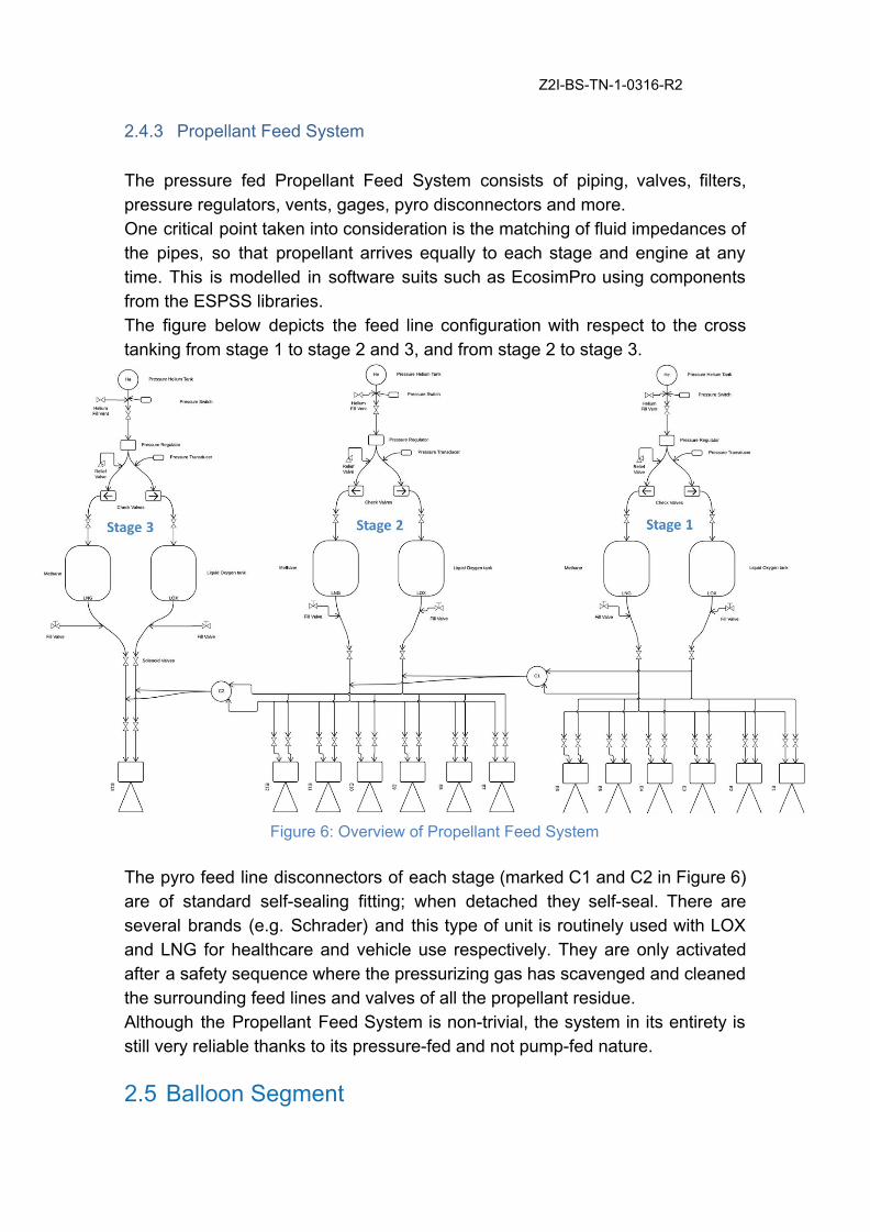
Z2I-BS-TN-1-0316-R2 2.4.3 Propellant Feed System The pressure fed Propellant Feed System consists of piping, valves, filters, pressure regulators, vents, gages, pyro disconnectors and more. One critical point taken into consideration is the matching of fluid impedances of the pipes, so that propellant arrives equally to each stage and engine at any time. This is modelled in software suits such as EcosimPro using components from the ESPSS libraries. The figure below depicts the feed line configuration with respect to the cross tanking from stage 1 to stage 2 and 3, and from stage 2 to stage 3.
Figure 6: Overview of Propellant Feed System
The pyro feed line disconnectors of each stage (marked C1 and C2 in Figure 6) are of standard self-sealing fitting; when detached they self-seal. There are several brands (e.g. Schrader) and this type of unit is routinely used with LOX and LNG for healthcare and vehicle use respectively. They are only activated after a safety sequence where the pressurizing gas has scavenged and cleaned the surrounding feed lines and valves of all the propellant residue. Although the Propellant Feed System is non-trivial, the system in its entirety is still very reliable thanks to its pressure-fed and not pump-fed nature.
2.5 Balloon Segment

Z2I-BS-TN-1-0316-R2 The balloon segment handles the first phase of the flight by lifting Bloostar to near-space. It also isolates the rocket from the rotation of the balloon and provides a telemetry/telecommand relay from the ground to the launcher. Consequently, the link range is extended significantly, eliminating the need for ground stations located along the initial flight path – further decreasing overall launch costs. The balloon segment consists of (in order of vertical flight position up to down):
● the High-Altitude Balloon ● the Flight Train ● the Gondola
2.5.1 High-Altitude Balloon The balloon required for lifting the launch vehicle, communications gondola and other equipment to the stratosphere is a 90,000 m3 balloon, which is comfortably within the range of high-altitude balloons that are commercially available. 2.5.2 Flight Train The flight train, located between the balloon and the gondola, hosts all the necessary equipment for a successful balloon operation, it consists of:
● several redundant GNSS beacons for recovery ● two C-band transponders (for the balloon operation and to comply with
Air traffic rules) ● two radar reflectors ● a flight termination system ● a telemetry system ● a ballasting system
2.5.3 Gondola The balloon gondola (Figure 7) has the capacity to point the launcher towards the preferred azimuthal direction for the rocket ignition. It also carries all the communication equipment dedicated for relaying rocket telemetry/telecommand.

Z2I-BS-TN-1-0316-R2
Figure 7: Balloon gondola configuration
2.6 Sea Launch Bloostar is launched on international waters from a ship. International waters enable regulatory ease and sea launch itself reduces the risk of launch delays due to bad weather by compensating the ground wind speed and direction with the ship’s speed and direction. Furthermore, it allows for flexible mission needs or range safety requirements by having a movable launch site and adapting the point of rocket-ignition. The launch ship itself does not need any significant adaptation for the launch operation (the reader is reminded that the ship only releases the Balloon-Powered assembly – there is no ignition of the rocket engines from the ship). Any ship with a sufficiently wide flat area could be rented to perform the flight. The effective launch area on deck should be of around 50x17 meters. One ideal location for launches is the south-west of the Canary Islands due to the generation of near zero wind speeds because of the geographic characteristics of the islands. This location is also excellent to reach any azimuth.

Z2I-BS-TN-1-0316-R2
3 BLOOSTAR TRAJECTORY AND PERFORMANCE
3.1 Flight Profile While each mission is unique, a typical flight profile can be as the following: the first phase of the flight is a balloon ascent to near-space (20-25 km) lasting 1.5-2h. The second phase of the flight starts once the rocket is released from the balloon. Shortly thereafter, all 13 engines are ignited. The first stage burns for 110 seconds, upon which the vehicle reaches an altitude of 80 km and an inertial speed of 2.3 km/s. After ejecting the first stage, the vehicle reaches 400 km and 4.4 km/s in 230 seconds. Upon third and final stage separation, the third stage performs multiple firings, the first one lasting 340 seconds and reaching 600 km of altitude while still slightly below the target orbital speed. Then, after coasting and later finalizing the orbit, the payload is released. Finally, a last engine boost is performed to de-orbit the third stage in order to minimize space debris left by the mission. Figure 8 depicts the stages of the flight, and a similar yet different flight profile to the above description is plotted in Figure 9.

Z2I-BS-TN-1-0316-R2
Figure 8: Flight cycle of Bloostar
Figure 9: Simulation of Altitude and Inertial Speed over Flight time
3.2 Performance Capability Bloostar vehicle’s payload capabilities are shown in Figure 10. The performance shown is the maximum capability from the Canary Islands. An additional payload spin (up to 10 RPM) can be provided before separation.

Z2I-BS-TN-1-0316-R2
Figure 10: Bloostar performance for circular orbits from the Canary Islands
3.3 Payload Insertion Accuracy Bloostar is capable to provide precise orbit insertion according to Table 3.
Orbit parameter Value
Altitude +/- 5 km
Inclination +/- 0.05 deg
RAAN +/- 0.05 deg
Table 3: Orbital Insertion Accuracy (1 sigma)
3.4 Reliability: Anomaly Response This chapter discusses the unlikely anomaly events that can occur during a flight, and describes how risk has been retired already at the architectural level by designing a robust vehicle from the ground up. Each unlikely event has a dedicated response strategy that will contain the anomaly and ensure a successful mission. 3.4.1 Engine ignition delay

Z2I-BS-TN-1-0316-R2 Since it is not possible to ignite the rocket engines while the vehicle is attached to the balloon, the rocket segment will be released first and shortly thereafter ignited. Therefore, it is necessary to ignite all engines simultaneously in order to avoid the vehicle entering into a spin. However, it is unlikely that all 13 engines will ignite at the exact same time. We have simulated whether the GNC is capable of controlling the vehicle while all the engines ignite and throttle up. A realistic delay was introduced between the time the vehicle was dropped from the balloon and the ignition of each individual engine. The steadfast results show that Bloostar remains securely controlled despite non-simultaneous engine start. 3.4.2 Engine out capability Once the rockets are ignited the GNC checks that all engines are delivering the correct thrust. In the unlikely event of thrust deviation or failed ignition on an engine, the opposing symmetrical pair on the same stage is shut down. The engines that remain on are actuated and throttled to ensure adherence to the nominal trajectory. Thanks to Bloostar’s highly redundant configuration, mission success is assured in the event of an engine-out on both the first and second stage separately, see Figure 11. This has been confirmed by Matlab, ZOOM and ASTOS simulations, indicating that Bloostar is able to perform its mission successfully in a wide range of off-nominal conditions, from initial torque at separation to engine out events.
Figure 11: Bottom view of tolerable engine out capability - stage 1 and 2 can have one
engine out each (marked red), plus their opposing pair
4 PAYLOAD ACCOMMODATION
4.1 Fairing Volume

Z2I-BS-TN-1-0316-R2 The fairing is attached to the first stage of the launcher. The payload has to fit within the dynamic envelope within the fairing. The following Figure 12 shows the dimensions.
Figure 12: Bloostar fairing available inner dimensions [mm]
The volume is approximately 2.4m3. Oversized payloads can be accommodated as special flights. The fairing is nearly transparent to RF so that the customer can continuously communicate with the satellite during ascent and launch. The internal pressure decay is controlled by a set of redundant valves.
4.2 Mechanical Interfaces The payload is attached to a mating plane at the center of the third stage. Depending on payload interface and size, Bloostar offers to accommodate most Primary and Secondary customer needs. The most commonly used small satellite separation systems and nanosat deployers are supported, such as:
● Planetary Systems’ Mark II Motorized Lightband (8-38.8 inch diameter) ● Planetary Systems’ Canisterized Satellite Dispenser (3, 6, 12, 27U sizes) ● Innovative Solutions in Space’s ISIPOD CubeSat Deployer (incl.
Quadpack) ● Dassault ASAP 5 ● Ruag Clamp Band Separation Systems ● Spaceflight Industries’ P-PODs (one or multiple cubesats up to 34cm
length) and Nanobox (6U, 12U, 24U sizes) ● Spaceflight Industries’ Adapter Mounts for Microsat-class <70kg (8 inch
separation ring) and ESPA-class <190kg (15 inch separation ring).

Z2I-BS-TN-1-0316-R2
4.3 Electrical Interfaces Bloostar provides standard payload electrical interfaces. Details surrounding connector type and pinouts will be specified in future versions of the PUG. The connection will provide power, data communication lines, and separation detection systems. Regulated 28V, 1A power is available to the payload during the flight.
4.4 Payload Requirements 4.4.1 Documentation Documentation required by the payload user is kept to a minimum and limited to that which is absolutely required in order to execute a mission successfully and safely. The single most important required document, containing the most relevant information, is the Launch Vehicle to Spacecraft Interface Control Document (ICD). This should include details of all interfaces (mechanical, electrical, etc.), but also all information needed to describe the mission and the interactions between launch vehicle and payload. Other documentation evidencing compliance to Qualification, Acceptance and Safety rules may be required as well. 4.4.2 Loads The payload must be robust and not suffer failure under the mechanical loads listed in chapter 5.2, with positive margin. Further information on resonance frequencies and mass properties will be provided in a future version of this PUG. 4.4.3 Configuration The primary payload Center of Gravity (CoG), relative to the plane of separation, must stay within a TBD offset detailed in a future version of this PUG. 4.4.4 Power, EMC and grounding Payloads are anticipated to be powered off during launch and should hence not emit any electromagnetic noise during the launch phase. Bloostar does allow for

Z2I-BS-TN-1-0316-R2 powered-on payloads during the launch phase, but these will be required to undergo a satellite-level EMC test to assure no interference with Bloostar’s own avionics systems. 4.4.5 Hazardous propellants, Pyros and Pressurized systems The use of hazardous propellants, pyrotechnic devices or pressured systems in the spacecraft is allowed but should be reported as early as possible in the mission planning process. 4.4.6 Safety An applicable User’s Safety Manual, based on the mission and the designated launch range, will be provided to the customer during a formal request. Until then, the AFSPCMAN 91-710 Range User’s Manual can be used as reference. It contains requirements for ground handling, payload mechanical, electrical, fluid system, ordnance and RF design.

Z2I-BS-TN-1-0316-R2
5 PAYLOAD ENVIRONMENTS The lack of a high dynamic pressure flight, acoustic ground reflections and turbo pumps significantly reduces the overall harshness of the trip for the satellite. However, all the environments should be taken into account, from transportation to final delivery into the desired orbit. Table 4 lists all the foreseen environmental conditions that the payload will experience. Ship environment Balloon ascent Stage 1 Stage 2 Stage 3
Duration 2 hours 2 hours ~2 min ~4 min ~7 min Cleanliness Payload
encapsulated in fairing
- - - -
Atmospheric Pressure
101 kPa Dropping from 101 kPa to 1kPa
- - -
Relative Humidity
30 to 60% Dropping from 60% to 0%
- - -
Thermal 21°C ± 5°C Dropping from 21°C to -50°C
TBD TBD TBD
Quasi-Static - - See Figure 13 Shock - - See Figure 14 Acoustic - - TBD, see chapter 5.2.4
Table 4: Summary of environmental conditions at various flight events
5.1 Ship environment The payload will be encapsulated in the launcher fairing during ship transport to launch location. Basic active environmental control is applied during this time, which is estimated to last 2 hours. An optional service to keep the fairing interior within ISO 8 (Class 100,000) will be available.
5.2 Mechanical The Maximum Predicted Environments (MPE) the payload will experience mechanically are described in this section. These are guidelines based on simulations that will need to be confirmed once test flights commence.

Z2I-BS-TN-1-0316-R2 5.2.1 Quasi-Static Loads Figure 13 describes the Quasi-Static Loads (QSL) envelop to be considered for the spacecraft qualification. This envelop corresponds to the static acceleration of the launcher during the ascent phase multiplied by a development and a qualification factor. Also a small contribution for the dynamic environment is added to the value.
Figure 13: Quasi-Static Loads
A maximum of 6.5g in compression and 1g in tension is expected for the longitudinal QSL. ±0.5g is the maximum lateral QSL expected. These values will be updated with flight experience and the reduction of the development factor. 5.2.2 Dynamic environment As there is no dense atmospheric phase and no turbo pump, the dynamic environment generated by the Bloostar flight is very low and mostly transient. The sine environment to be considered is <0.1g for longitudinal and lateral direction on the low frequency range (0-200Hz). 5.2.3 Shock Environment The maximum shock encountered by the payload occurs during payload separation. Several low-shock hold down release technologies, both pyrotechnic and free-of-pyrotechnics, are currently being evaluated. As an example the Pyrosoft from La Croix offers the Shock Response Spectrum (SRS) depicted in Figure 14.

Z2I-BS-TN-1-0316-R2
Figure 14: Bloostar shock response spectrum
5.2.4 Acoustic Environment The acoustic vibration loads are greatly diminished compared to conventional ground based launches, because of the following:
● No aerodynamic buffeting, since flight takes place in highly rarified air. ● Air pressure and density is drastically reduced. ● No acoustic reflection from the ground, since the ground is more than
20km away from the launcher at ignition. The intensity of the actual vibrations will be updated when further testing and analysis become available. 5.2.5 Random vibration The random vibration loads are greatly diminished compared to conventional ground based launches, because of there are very little engine vibrations, since the engines lack turbo pumps. The intensity of the actual vibrations will be updated when further testing and analysis become available.
5.3 Thermal, Atmospheric and Cleanliness After release from the ship, the balloon ascent environment will be steady dropping ambient sea air atmosphere. The payload is during this period encapsulated from surrounding weather by the launch fairing. If any other cleanliness environment is required, the payload experimenter should contact Z2I.
Z2I-BS-TN-1-0316-R2 Thermal impact after fairing release during powered flight through ambient free molecular atmosphere is expected to be small and will be discoursed in a future version of this PUG.
5.4 RF and EMC The RF and EMC environment of the payload, with and without the fairing, including intentional and spurious emissions, have to be analyzed and will be presented here in a future edition. The fairing is nearly transparent to RF.

Z2I-BS-TN-1-0316-R2
6 LAUNCH CAMPAIGN Z2I provides each customer with a Mission Manager who acts as a single point of contact and guides the customer from contract award and all the way through the launch campaign. Bloostar model embraces a light and swift launch campaign, where the customer is offered one of the industry’s most agile flight timelines.
6.1 Typical Mission Timeline A typical mission timeline entails the following major milestones:
● Signing of contract: 6 months prior to launch ● Launch campaign and payload delivery: 2 weeks prior to launch ● Launch Readiness Review: 2 days prior to launch
The launch campaign starts with the delivery of the payload to the Z2I facilities on the island of La Palma, located nearby the launch ship’s home port. In these facilities, the payload goes through final processing and checkout, standalone tests, ordnance installation, fueling, and encapsulation with the payload fairing. Next, the encapsulated spacecraft is mated onto the Bloostar launch vehicle. The complete assembly goes through integrated testing. Once this is complete, the integrated launch vehicle is attached to the Balloon Segment (non-filled) and electrical checkout and RF end-to-end tests are conducted. The entire assembly is then moved to the launch ship. The ship then leaves port heading for the launch location where the Balloon Segment is prepared for flight and attached to the launch vehicle before final release and Balloon-powered ascent.
6.2 Facilities A workspace office type area will be provided for customer teams, equipped with desks, power and internet. The clean room facilities used for payload processing, integration, encapsulation and storage are certified at a ISO 7 level (Class 10,000). Environmental levels for particles, relative humidity and temperature will be monitored at all times.
6.3 Additional Services

Z2I-BS-TN-1-0316-R2 The following services can be offered to the customer upon request, and is considered outside the standard offering:
● Payload fueling (only non-toxic fuels) ● A cleanliness level of ISO 8 (Class 100,000) whilst on board the launch
ship (basic active environmental conditioning is standard) ● Gaseous Nitrogen (GN2) purge whilst on board the launch ship
6.4 Post Launch Deliverables Near real-time status of key flight events (balloon monitoring and release, engine burns, fairing jettison, payload separation) will be provided during launch. Within one hour of payload separation, the customer will be provided with injection orbit details for each payload in the form of Two Line Elements (TLEs), Injection Accuracy, Separation State Vector, Separation Attitude and Spin rates.


