1
A Review on Tool Wear Mechanisms in Milling of Super
Alloy
Laveena Makaji, Mithilesh Gaikhe, Vivek Mahabale, Naval Gharat
Saraswati College of Engineering, Kharghar, Navi Mumbai
Abstract: Super alloys have vast range of
applications in gas turbine engines of aircraft due
to their ability to withstand all the mechanical
properties at elevated temperature. Super alloys
are di fficult to cut material which involves large
amount of cutting forces while its machining.
These large cutting forces lead to frequent tool
wear which consumes tool replacement time and
cost. This work deals with the review of various
tool wear mechanism in cutting of super alloys for
proper selection of tools for particular material.
Key words : BUE, Crater wear, Flank wear, notch
wear.
INTRODUCTION
Super alloys have vast range of applications
like Gas turbine Engine, Reciprocating engines etc.
Inconel718 is a Nickel based super alloy which is
used in high temperature applications like
combustion chambers of Gas Turbine Engines and
Steam Turbine Engines, [4]. The applicat ions
involving Inconel718 undergo large fluctuating
thermal stresses. If Inconel718 material with high
surface roughness is used in such part, the material
may fail to its earliest as high surface roughness act
as minute notches which increases the stress
concentration on the surface. In order to achieve good
surface quality lower values of feed rate and depth
cut is required which affect productivity to the
greater extent and also at high speed cutting force
increases simultaneously.
Super alloys
It is an alloy based on group VII elements
(Nickel, cobalt, or iron with high percentage of nickel
added) to a multip licity of alloying elements are
added. The defining feature of a super alloy is that it
demonstrates a combination of relatively high
mechanical strengths and surface stability at high
temperature [12].
Nickel-Iron-base alloys
This type of super alloys possess high
toughness and ductility and are used in applications
where this properties are required e.g. turbine d iscs
and forged rotors. Their cost is low due to substantial
amount of iron added. There are three groups of
nickel iron based super alloy. Nickel-Iron based
super alloys are known for their high toughness and
ductility and are been used in many such applications
where these properties are required at elevated
temperatures and pressures. (I)Precipitation-hardened
alloys (ii) Low-coefficient-of-thermal expansion (iii)
Modified stainless steels
Cobalt-base super alloys
Cobalt-base super alloys have superior high
corrosion resistance hence it is used in applicat ions
where hot corrosion is required. These alloys sustain
International Journal of Scientific & Engineering Research, Volume 6, Issue 12, December-2015 ISSN 2229-5518
IJSER © 2015 http://www.ijser.org
220
IJSER
2
this property at many range of temperatures from
moderate to high. They are used in GTEs in vanes
and other stationary components because of their
stress ruptured properties and hot corrosion
resistance. The microstructure of cobalt based super
alloys consist of a small FCC gamma matrix with a
number of strengthening faces. They have high
thermal fatigue resistance and welding ability.
Nickel-base super alloys
These super alloys have high temperature
and strength combination. The capability of
sustaining high temperature in nickel base super
alloys is due to the precipitation of high volume
fraction of the Ni3.They are known for h igh strength
and creep resistance at elevated temperatures.
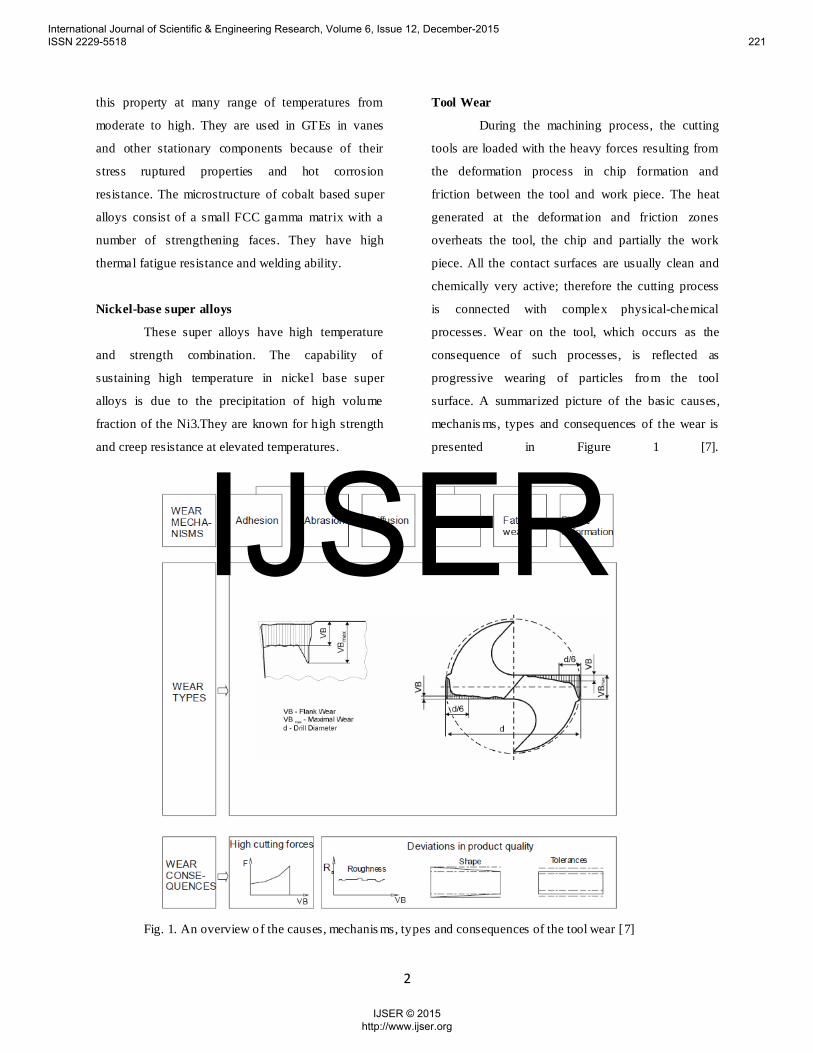
Tool Wear
During the machining process, the cutting
tools are loaded with the heavy forces resulting from
the deformation process in chip formation and
friction between the tool and work piece. The heat
generated at the deformat ion and friction zones
overheats the tool, the chip and partially the work
piece. All the contact surfaces are usually clean and
chemically very active; therefore the cutting process
is connected with complex physical-chemical
processes. Wear on the tool, which occurs as the
consequence of such processes, is reflected as
progressive wearing of particles from the tool
surface. A summarized picture of the basic causes,
mechanis ms, types and consequences of the wear is
presented in Figure 1 [7].
Fig. 1. An overview of the causes, mechanis ms, types and consequences of the tool wear [7]
International Journal of Scientific & Engineering Research, Volume 6, Issue 12, December-2015 ISSN 2229-5518
IJSER © 2015 http://www.ijser.org
221
IJSER
3
Tool wear is generally considered to be a
result of mechanical (thermo-dynamic wear, mostly
abrasion) and Chemical (thermo-chemical wear,
diffusion) interactions between the tool and work
piece. The temperature at the contact zone might
raise or exceed the level of the resistivity of the
cutting materials, which results as increased crater
wear, chipping of the cutting edge or even
catastrophic damages to the tool tip.
Types of wear include:
1. Flank wear in which the portion of the tool
in contact with the finished part erodes. Can
be described using the Tool Life Expectancy
equation.
2. Crater wear in which contact with chips
erodes the rake face. This is somewhat
normal for tool wear, and does not seriously
degrade the use of a tool until it becomes
serious enough to cause a cutting edge
failure.
3. Built-up edge in which material being
machined builds up on the cutting edge.
Some materials
(notably aluminum and copper) have a
tendency to anneal themselves to the cutting
edge of a tool. It occurs most frequently on
softer metals, with a lower melt ing point. It
can be prevented by increasing cutting
speeds and using lubricant. When drilling it
can be noticed as alternating dark and shiny
rings.
4. Glazing occurs on grinding wheels, and
occurs when the exposed abrasive becomes
dulled. It is noticeable as a sheen while the
wheel is in mot ion.
5. Edge wear, in drills, refers to wear to the
outer edge of a drill bit around the cutting
face caused by excessive cutting speed.
LITERATURE S URVEY
Literature survey on flank wear
Choudhary and El Baradie [4] studied machinability
using different cutting tools like cemented tungsten
carbide tool, ceramic tool, cubic boron nitride was
performed. It was concluded that resistance towards
depth of cut, notch wear was equal to salon and
silicon carb ide.
Miroslav Janos and Ivan Mrkvica[14] carried out
with different combinations of feed and cutting
speed. The most optimal cutting conditions were
found out by measuring the milling time till vert ical
wear was reached and the cutting inserts used were
not able to machine. By us ing optimum cutting
parameters cutting tool material and geometry of tool
machining of Inconel 718 was made economical and
effective.
J.P.Costes et al [8]analyzed the studies made for the
wear of CBN tools, a description of the modes of
degradation is given: during machin ing, the work
piece, under high temperatures and stresses,
plasticized itself superficially, so the alloy spread on
the contact area between the insert and the work
piece (rake and flank faces). They concluded that the
dominant wear mechanis ms of the CBN cutting tool
during the cutting process are adhesion, then
diffusion and finally abrasion.
Zhaopeng Hao et al [13]analyzed Tool wear
mechanis m in dry machining Inconel718 with coated
cemented carbide tools. CCD and scanning electron
microscopy (SEM) equipped with energy dispersive
X-ray spectrometer (EDS) were used to study tool
wear mechanism. According to analysis of tool wear
International Journal of Scientific & Engineering Research, Volume 6, Issue 12, December-2015 ISSN 2229-5518
IJSER © 2015 http://www.ijser.org
222
IJSER
4
mechanis m, tool flank wear model was established.
The optimal temperature in machin ing Inconel718
with PVD-coated (TiAlN) tool was obtained through
the established model.
Oguz Colak [15] carried out experiment using
Taguchi L18 with three different cutting speed and
feed rate and two different depth of cuts. Cutting
forces components and tool flank wear were the main
parameters seem for optimization. High pressure
cooling helps in good surface fin ish but results in
decreased cutting force components.
Literature survey on Built up Edge
M. A. Hadia et al[19] studied tool wear mechanism
and tool life in ball nose under Minimum Quantity of
Lubricant (MQL) condition fo r Inconel718 during
end milling. Main aim was to focus on comparison of
up-milling and down-milling operation using
Physical Vapour Deposition (PVD) and using coated
carbide inserts. This experiment reveals that tool
wear increases with increase in DOC, feed rate and
cutting speed. Significant pitting and notch wear
were the major failure mode typically located near
the DOC line that affecting tool performance.
H.R. Krain et al [11] studied effects of changing
operation parameters on tool life, productivity and
wear pattern. Experiments were conducted to find out
the influence of feed rate and immersion ratio on tool
life with proper tool material and geometry. Further
experiments were done using reduced number of
operating parameters to examine the influence of tool
material and geometry.
E.O Ezugwo et al [6] carried out machining of
different super alloys using different tools like CBN
and PCD was observed. Conventional coolant
application is not enough as formation of vapour
blanket enables it to reach the interface. Machining of
high speed aerospace alloys can be achieved by
combination of appropriate tool material and
machining technique.
S.A. Khan et al [16] experimented finish turning of
Inconel 718 using low concentration PCBN inserts.
At the lowest cutting speed (150m/min), average tool
life using the round insert was approximately 5 t imes
longer in comparison to the C-type tool, with severe
grooving and built up edge (BUE) format ion
observed on wear scar micrographs in all experiments
with the latter. As cutting speed was increased to
300m/min, the presence of grooving and BUE
dimin ished, leading to comparable performance
between the C-type and round tools.
Waseem Akhtar et al [21] studied review of the tool
wear mechanism in the machin ing of nickel based
super-alloys .It has revealed about the tool wear
mechanis ms in the machining of these alloys.
Adhesion wear was found to be the main
phenomenon leading to the cutting tool wear in this
study. At medium cutting speeds, adhesion of the
work piece material onto the tool surface in the form
of BUE or BUL caused tool failure by attrit ion
phenomenon.
Irfan Ucun et al [20] studied the effects of the coating
material and MQL system were examined in the
milling of Inconel 718 nickel under micro conditions.
As a result of the experimental study, flank wear was
observed due to the abrasive wear mechanism, which
is the most frequently observed wear type. Local
fractures on the cutting edges and sides of the cutting
tools as a consequence of fatigue and BUE format ion
were observed.
International Journal of Scientific & Engineering Research, Volume 6, Issue 12, December-2015 ISSN 2229-5518
IJSER © 2015 http://www.ijser.org
223
IJSER
5
Literature survey on notch wear
T.Kitagawa et al [3] performed cutting experiments
and numerical analysis up to a cutting speed of
600m/min for investigating temperature and wear of
cutting tools. Experiment revealed that feasibility of
high speed end milling depends on transient
temperature rise or time lag, owing to a shortcut
distance of the tool edge per single revolution,
existence of helix angle and temperature drop
through the use of coolant.
Miroslav zetek et al [22] did an experiment dealing
with measuring the tool wear on the flank face VB,
on monitoring the cutting forces and work piece
quality. For longer tool life all the parameters should
possess optimum values this article presents the
important factors during the optimization process.
Relation between edge radius and cutting tool life is
evident. In terms of reliab ility it was found desirable
to have linear tool wear without maxim tool wear and
notches or other defects. This increased the overall
safety, reliability and cutting tool efficiency, and this
is desirable when machining super alloys.
Kejia Zhuang et al [23] observed the wear
mechanis m of alumina based ceramic cutting tools
during dry turning of Inconel718 is experimentally
investigated. Based on the observation of tool wear,
an attempt by employing the hardened layer beneath
the work p iece surface is made to explain the
occurrence of notch wear. Consequently, predictive
model of notch wear depth considering the influence
of work hardened layer is developed. Series of
cutting tests are used to validate the proposed notch
wear model, and the result indicates that the
proposed model is feasible.
M.S.Kasim et al [18] investigated tool wear using a
ball-type end mill. Notch wear and flaking near the
depth of the cut zone were the predominant types of
tool failure for the four round cutting tools and were
initiated by pitting caused by the repetitive cyclic
load. The combination of notch wear and flaking
caused the cutting edge to fail abruptly.
A. Shokrania et al [17] annealed Inconel718 with
dimensions 100mm x 150mm x 50mm is used in this
paper. Cutting tool for machining trials is disposition
(PVD) TiAlN coated solid carbide end mill. Most
effective approach was studies for machining and
nickel based alloys for penetrating a small amount of
cryogen in to the cutting zone. It was found that
cryogenic cooling produces a better surface finish
than dry machining. Cryogenic cooling significantly
reduced the tool life to the coated solid carbide end
mills.
Seref Aykut et al [9] Cutting forces (Fx, Fy and Fz)
which are formed on symmetric face milling of
cobalt based super alloy by using TiN/TiCN/TiAlC
PVD coated and uncoated tool hard metal insert are
measured experimentally. Chip morphology and tool
wear were compared by using PVD coated tool and
uncoated tool hard metal inserts which are obtained
depending on feed rate, cutting speed and cutting
depth.
Literature survey on Crater wear
Jorge A. Olortegui-Yume and Patrick Y. Kwon [10]
Steady-state turning experiments were carried out
with mult ilayer coated inserts consisting of
TiN/Al2O3/TiCN deposited on a carbide substrate.
The delamination in the coatings of MLCTs earlier
was not observed in the MLCTs despite of the fact
that similar machin ing conditions have been
employed. This study indicates that the multilayer
coating studied resists crater wear mainly because of
the obstruction of depth growth by means of a second
International Journal of Scientific & Engineering Research, Volume 6, Issue 12, December-2015 ISSN 2229-5518
IJSER © 2015 http://www.ijser.org
224
IJSER
6
layer(Al2O3) with a low dissolution potential into
steel.
S.K. Choudhury and Ganga Raju [5] this paper
presents the effects of spindle rotational speed and
feed rate on the crater wear along the lip of a drill.
Crater wear has been recommended for acceptance as
a performance index owing to the relative ease with
which it can be measured and the fact that, at higher
speeds, crater wear is more significant than flank
wear.
Literature survey on glazing
M. M. Hamdy and R. B. Waterhouse [1] investigated
the fretting wear of Ti-6Al-4V and Inconel718 with
A sphere-on-flat configurat ion. Glaze formation on
Inconel718 occurs at 540°C at both amplitudes of slip
but only at an amplitude of 40 µm at 280 °C. The
wear rate and coefficient of friction decrease when
the glaze is present. Glaze fo rms on the alloy Ti-6Al-
4V at temperatures of 200 °C and above but tends to
break down at 600 “C owing to creep of the
underlying material. R.B. Waterhouse [2]observed
that in nickel-based alloy, Inconel 718, developed
glaze oxide when fretted at 540°C in air, as indicated
by a low coefficient of friction and wear rate. The
glaze type oxide forms a spinel type structure on
nickel alloys which results in low fretting wear at
high temperature.
CONCLUS ION
This paper dealt with various types of tool wear
mechanis ms involved in machining of super alloys.
Tool wear mechanisms like Flank wear, Crater wear,
Built up edge, Glazing and edge wear is discussed in
this work.
REFERENCES
M. M. Hamdy and R. B. Waterhouse, “The fretting
wear of ti-6ai-4v and aged Inconel 718 at elevated
temperatures", Wear, 71 ,pp. 237 – 248,1981
[1] R.B. Waterhouse, “Fretting at high
temperatures”, TRIBOLOGY international
August 1981,pp 203-208, 1981
[2] T. Kitagawa, A. Kubo, K. Maekawa, ''
Temperature and wear o f cutting tools in
high-speed machining of Incone1718 and
Ti-6A1-6V-2Sn'', wear 202, pp.142-14,1997
[3] I.A. Choudhury, M.A. El-Baradie,
“Machinability of nickel-base super alloys: a
general review”, Journal of Materials
Processing Technology 77, pp. 278–284,
1998
[4] S.K. Choudhury , Ganga Raju,
“Investigation into crater wear in drilling” ,
International Journal of Machine Tools &
Manufacture 40 ,pp. 887–898, 2000
[5] S.A. Khanna, S.L. Soo, D.K. Aspinwall, C.
Sage, P. Harden, M. Fleming, A. White,R.
M’Saoubi,” Tool wear/life evaluation when
fin ish turning Inconel 718 using PCBN
tooling”, 5th CIRP Conference on High
Performance Cutting 2012,pp 283-288, 2012
[6] S. Dolinšek, J. Kopač, “Mechanism and
types of tool wear; particu larities in
advanced cutting materials’’, Journal of
Achievements in Materials and
Manufacturing Engineering, volume 19,
issue 1 ,November 2006
International Journal of Scientific & Engineering Research, Volume 6, Issue 12, December-2015 ISSN 2229-5518
IJSER © 2015 http://www.ijser.org
225
IJSER
7
[7] J.P. Costes, Y. Guillet, G. Poulachon, M.
Dessoly, “Tool-life and wear mechanisms of
CBN tools in machin ing of Inconel 718”,
International Journal of Machine Tools &
Manufacture 47, pp.1081-1087,2007
[8] Seref Aykut , Eyup Bagci , Aykut Kentli,
Osman Yazıcıog˘lu , “Experimental
observation of tool wear, cutting forces and
chip morphology in face milling of cobalt
based super-alloy with physical vapour
deposition coated and uncoated tool”,
Materials and Design 28 ,pp. 1880–
1888,2007
[9] Jorge A. Olortegui-Yume and Patrick Y.
Kwon, “Crater Wear Evolution in Multilayer
Coated Carbides During Machining Using
Confocal Microscopy”, Journal of
Manufacturing Processes Vol. 9/No. 1,2007
[10] H.R. Krain, A.R.C. Sharman, K. Ridgwa,
“Optimisation of tool life and productivity
when end milling Inconel718”, Journal of
Materials Processing Technology 189,
pp.153–161, 2007.
[11] Blaine Geddes, Hugo Leon, Xiao Huang,
2010, “Super alloys Alloying and
Performance”, United States of
America,pp.18-35
[12] Zhaopeng Hao , DongGao , YihangFan ,
RongdiHan, “New observations on tool wear
mechanis m in dry machining Inconel718”,
International
JournalofMachineTools&Manufacture51,97
3–979,2011
[13] Miroslav Janos, Ivan Mrkvica, “Milling
Possibilities of Material Inconel718”,
Manuf. and Ind. Eng., 11(4), ISSN 1338-
6549 Facu lty of Manuf. Tech. TUKE,2012
[14] Oğuz Çolak, “Investigation on Machining
Performance of Inconel 718 under High
Pressure Cooling Conditions” Strojniški
vestnik - Journal of Mechanical Engineering
58 11,pp. 683-690, 2012
[15] S.A. Khana, S.L. Soo, D.K. Aspinwall, C.
Sage, P. Harden, M. Fleming, A. White,R.
M’Saoubi,” Tool wear/life evaluation when
fin ish turning Inconel 718 using PCBN
tooling”, 5th CIRP Conference on High
Performance Cutting 2012,pp 283-288, 2012
[16] A. Shokrani, V. Dhokia, S.T Newman, R.
Imani-Asrai, ''An Init ial Study of the Effect
of Using Liquid Nitrogen Coolant on the
Surface Roughness of Inconel718 Nickel-
Based Alloy in CNC Milling'', Procedia
CIRP 3,pp. 121 – 125, 2012
[17] M.S. Kasim , C.H.CheHaron , J.A.Ghani ,
M.A.Sulaiman , M.Z.A.Yazid , “ Wear
mechanis m and notch wear location
prediction model in ball nose end milling of
Inconel718” , Wear 302 ,pp. 1171–1179,
2013
[18] M. A. Hadia, J.A. Ghania, C.H. Che Harona,
M. S. Kasim, “Comparison between up-
milling and down-milling operations on tool
International Journal of Scientific & Engineering Research, Volume 6, Issue 12, December-2015 ISSN 2229-5518
IJSER © 2015 http://www.ijser.org
226
IJSER
8
wear in milling Inconel 718”, Procedia
Engineering 68,pp. 647 – 653, 2013
[19] Irfan Ucun , KubilayAslantas , FevziBedir ,
“An experimental investigation of the effect
of coating material on tool wear in micro
milling of Inconel 718 super alloy”, Wear
300 ,pp. 8–19,2013
[20] Waseem Akhtar, Jianfei Sun, Pengfei Sun,
Wuyi Chen, Zawar Saleem, “Tool wear
mechanis ms in the machining of Nickel
based super-alloys: A review”, Front. Mech.
Eng. 2014, 9(2): 106–119, 2014
[21] Miroslav Zetek, Ivana Česáková, Vojtěch
Švarc, ''Increasing Cutting Tool Life when
Machining Inconel718'', Procedia
Engineering 69,pp. 1115 – 1124, 2014
[22] KejiaZhuang, DahuZhu, XiaomingZhang,
Handing, “Notch wear prediction model in
turning of Inconel718 with ceramic tools
considering the influence of work hardened
layer” ,Wear313,pp 63–74, 2014
International Journal of Scientific & Engineering Research, Volume 6, Issue 12, December-2015 ISSN 2229-5518
IJSER © 2015 http://www.ijser.org
227
IJSER


![Chris Brindley slides [Read-Only] - Amazon Web Services · "Never neglect details. When everyone‘s mind is dulled or distracted the leader must be doubly vigilant." Strategy equals](https://static.documents.pub/doc/80x56/5fbb9dc2e9245c45545ca9dd/chris-brindley-slides-read-only-amazon-web-services-never-neglect-details.jpg)


