21
Series 70 ePODs: Type-N Stac Transfer Switch → Distribuon The Foundaon Layer Product Brochure
| Date post: | 13-Apr-2017 |
| Category: |
Technology |
| Upload: | layerzero-power-systems-inc |
| View: | 96 times |
| Download: | 1 times |
Series 70 ePODs: Type-NStatic Transfer Switch → Distribution
The Foundation Layer
Product Brochure

ePODs Type-N STS/PDU Purpose
ePODs Type-N Is Inspired by NFPA-70E
The Series 70 ePODs Type-N design provides switching between two independent power sources, while providing power
distribution capabilities at the same switching voltage. Type-N ePODs provide the ability to transfer power between two or three
sources in a quarter of an electrical cycle, while delivering that power to up to twelve sub-feed circuit breakers.
The LayerZero ePODs: Type-N PDU Increases Operator Safety
Power Distribution Unit Series 70 ePODs: Type-N
2 © Copyright 2016 LayerZero Power Systems, Inc.

; Optional Triple Modular Redundancy: TMR Contains Fully-Independent Control Paths With No Single Point-Of-Failure
; Safe Bypass Procedure: Mechanical Bypass Interlock Eliminates Human Error When Performing Bypass Procedures
; Voice Guided Bypass: Step-By-Step Instructions With Audio and Video Guidance To Assist Operators Through Bypass
; Convection Cooling: Natural Convection-Cooled Heat Dissipation System is Maintenance-Free
; Epoxy Coated Buswork: Maximizes Reliability By Eliminating The Possibility of Bus-To-Bus Faults
; Silver Plated Terminals: Silver Has Excellent Conductivity To Provide Superior Electrical Performance and Reliability
; Maintenance-Free Joints: Brazed Joints Are Permanent And Maintenance-Free, Maximizing Product Life
; Machined Hardware: Machined Cap Screws and Engineered Disc Springs Maintain Constant Torque Throughout Product Life
; Screw Thread Inserts: Prevents Screws From Loosening Under Vibration For Long-Term Reliability
; Optical Fiber Based Controls: Eliminates Noise and Interference While Isolating Components from High Voltage
; Serialized Critical Board Tracking: Critical Boards Are Serialized And Cataloged in an Active Database For Traceability
; Transformer Vibration Isolation: Vibro-Elastic Pads to Absorb Vibrations from the Transformer
Reliability
LayerZero’s ePODs: Type-N Is Equipped Fully-Loaded
Safety
; InSight™ IR Portholes: Bolted Connections & Critical Boards Can Be IR Scanned With the Dead-Front Doors Closed
; Sectionalized Components: Isolated Sections That Can Be Safely De-Energized For Performing Maintenance
; Polycarbonate Windows: Allows Critical Board LEDs To Be Viewed With The Dead-Front Door Closed
; Front-Only Access: Installation and Maintenance Can Be Safely Performed Without Side or Rear Access
; Dead Front Hinged Doors: Barrier To Provide A Safe Working Area With No Exposed Live Parts
; SafePanel™ Distribution: NFPA-70E Inspired Finger-Safe Panel Board With No Exposed Live Parts
Connectivity
; Ethernet Connectivity: Secure VPN Router Connects To Network For Advanced Remote Monitoring Capabilities
; Modbus/TCP: Open Connectivity to Existing Monitoring Systems Without Proprietary Limitations
; NTP Time Clock Synchronization: Facilitates Timeline-Based Logging For Post-Event Reconstruction
; SNMP Connectivity: Permits Remote Management Via Simple Network Management Protocol
; Real-Time Waveform Capture: Automatically Captures A Picture Of The Power Three-Cycles Before and After Every Event
; Local Touch-Screen Interface: Password-Protected Color Touch-Screen GUI For Local STS Setup/Operation/Administration
; Black-Box Forensics: Captures and Records All Events To Provide Vital Information In Root-Cause Analysis
; Waveforms Automatically Emailed: Capability to Send Waveform Captures To Designated Individuals For Every Transfer
Power Distribution Unit Series 70 ePODs: Type-N
3 © Copyright 2016 LayerZero Power Systems, Inc.

eSTS:Size: 250A, 400AVoltage: 480V, 3-W, 600V, 3-WRedundancy: Triple Modular Redundant (TMR)Single Module Redundant (SMR)Output Switch: Redundant, Non-redundant
Main Circuit Breaker Section: MCB optionalMounting: Fixed, Plug-InType: Molded Case Switch65kA, 100kAElectronic Trip 65kAIC, 100kAICAccessories: CB Shunt-trip120VAC, 24VDCCB Position Indication: Open, Tripped, Closed
Distribution Section: Sub-feed distribution1200A SafePanel
ePODs: Type-N Output Feeds Directly to PDUs
Power Distribution Unit Series 70 ePODs: Type-N
4 © Copyright 2016 LayerZero Power Systems, Inc.
Equipment Layout

Color Touch Screen
Main Circuit Breakers,Power Quality Monitoring
SafePanel™ Distribution
15” Color Touch Screen (Standard)
1. Stereo Speakers for Guided Bypass Prompts
2. Output On Light
3. Alarm & Bypass Indicator
4. SCB Status Indicator
5. Logged In User
6. Navigation Menu
7. Customer & Project Information
8. Date & Time
1 2
34 5
6
207 8
Power Distribution Unit Series 70 ePODs: Type-N
5 © Copyright 2016 LayerZero Power Systems, Inc.
Equipment Layout
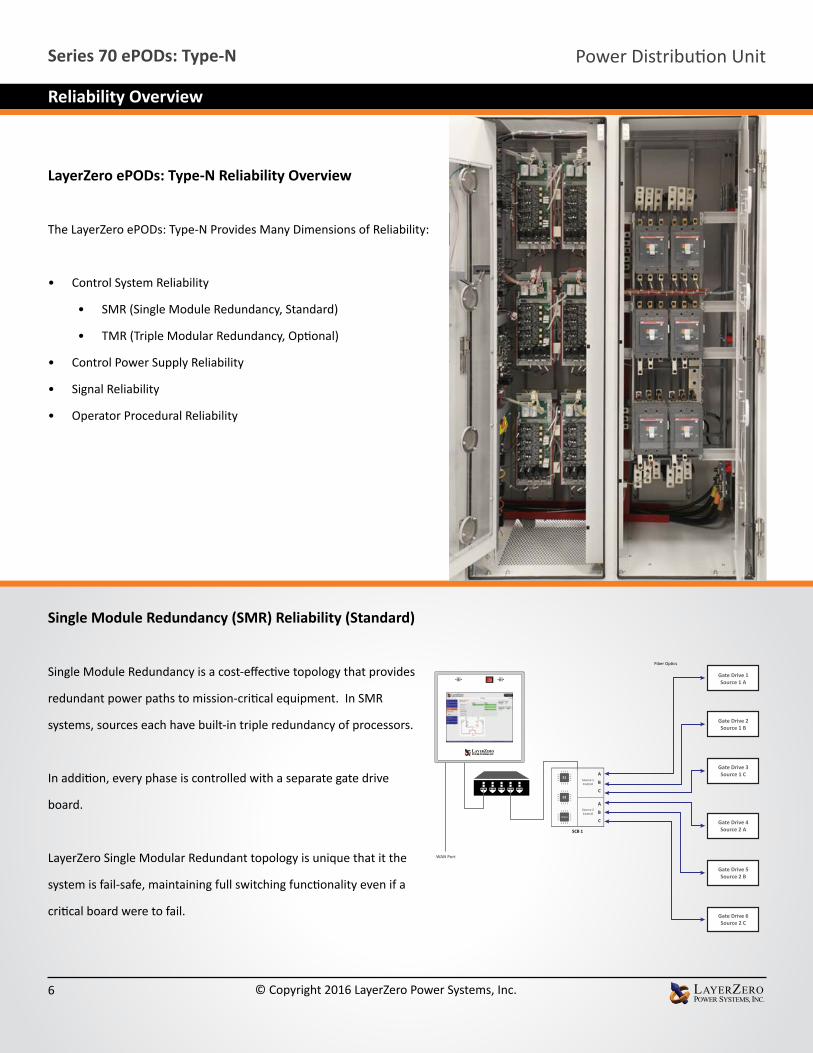
LayerZero ePODs: Type-N Reliability Overview
The LayerZero ePODs: Type-N Provides Many Dimensions of Reliability:
• Control System Reliability
• SMR (Single Module Redundancy, Standard)
• TMR (Triple Modular Redundancy, Optional)
• Control Power Supply Reliability
• Signal Reliability
• Operator Procedural Reliability
Gate Drive 1Source 1 A
Gate Drive 2Source 1 B
Gate Drive 3Source 1 C
Gate Drive 4Source 2 A
Gate Drive 5Source 2 B
Gate Drive 6Source 2 C
Source 1 Control
Source 2 Control
WAN Port
Fiber Optics
SCB 1
Single Module Redundancy (SMR) Reliability (Standard)
Single Module Redundancy is a cost-effective topology that provides
redundant power paths to mission-critical equipment. In SMR
systems, sources each have built-in triple redundancy of processors.
In addition, every phase is controlled with a separate gate drive
board.
LayerZero Single Modular Redundant topology is unique that it the
system is fail-safe, maintaining full switching functionality even if a
critical board were to fail.
Power Distribution Unit Series 70 ePODs: Type-N
6 © Copyright 2016 LayerZero Power Systems, Inc.
Reliability Overview

Power Distribution Unit Series 70 ePODs: Type-N
7 © Copyright 2016 LayerZero Power Systems, Inc.
Reliability Features: Triple Modular Redundancy (TMR) *Optional
eSTS TMR Triple Redundant Power Supply Architecture Has All Redundancy Features of SMR Architecture, Plus:
Each STS has three independent sets of analog and digital data acquisition and control systems. There is no direct communication between the three systems. The three systems do not even share a common system clock.
• Each control system acquires voltage and current data independently
• Each control system determines whether a source is good/bad independently
• Upon loss of a source, each control system makes decisions to transfer independently
Each SCR pair is driven by three separate actuators (gate drives)
Even if an entire control path or its subcomponent were to fail; and then if the active power source were to fail, the STS is designed to meet its emergency transfer specifications. It is able to complete its mission of transferring to the alternate source.
Gate Drive 1Source 1 A
Gate Drive 2Source 1 B
Gate Drive 3Source 1 C
Gate Drive 4Source 2 A
Gate Drive 5Source 2 B
Gate Drive 6Source 2 C
Source 1 Control
Source 2 Control
Source 1 Control
Source 2 Control
Source 1 Control
Source 2 Control
WAN Port
Fiber Optics
SCB 1
SCB 2 (TMR)
SCB 3(TMR)

Power Distribution Unit Series 70 ePODs: Type-N
8 © Copyright 2016 LayerZero Power Systems, Inc.
eSTS SMR Triple Redundant Power Supply Architecture
Divided into four (4) logical failure groups:
• System controls• Source 1 gate drives• Source 2 gate drives• Peripherals.
The three (3) available source of power from which to supply control power to each failure group are:
• Source 1• Source 2• STS Output.
LayerZero’s STS design incorporates twelve (12) power supplies (3 power sources x 4 failure groups.) The resultant control power topology utilizes all possible power paths to the four logical STS failure groups; and is the most comprehensive and redundant power supply system in existence.
Reliability Features: Single Module Redundant (SMR) Redundancy
PeripheralsPS 1
S1 A-B
Source 1 A B C
Source 2 A B C
PS 4S1 B-C
PS 7S1 A-C
PS 10S1 A-B
PS 3S2 B-C
PS 6S2 A-C
PS 9S2 A-B
PS 12S2 B-C
System Controls
Gate Drives, Source 1
Gate Drives, Source 2
GD 1 GD 3 GD 5
SCB 1 SCB 2TMR Only
SCB 3TMR Only
GD 2 GD 4 GD 6
PS 5Out A-B
System Controls
PS 8Out B-C
Gate Drives S1
PS 11Out A-C
Gate Drives S2
PS 2Out A-C
Peripherals
Output Bus
ABC
eSTS SMR Triple Redundant Processors
• Separate/independent processors for Source 1, Source 2 and Output power quality analysis
• If Source 1 processor malfunctions then system is able to be commanded to transfer to Source 2; & vice versa.
• If main control system fails then STS continues to conduct power to the load from the existing source of power. (However STS is unable to transfer to the other source)
• Each phase of each source is controlled with a separate gate drive circuit board.
S1 S2 Output
Gate Drive 1
Gate Drive 2
Gate Drive 3
Gate Drive 4
Gate Drive 5
Gate Drive 6
A B C A B CSource 1 Transfer Control Source 2 Transfer Control
Power Distribution Unit Series 70 ePODs: Type-N
9 © Copyright 2016 LayerZero Power Systems, Inc.
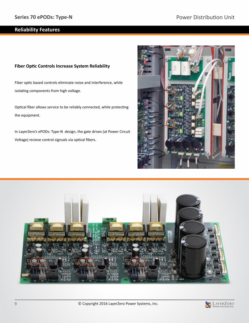
Fiber Optic Controls Increase System Reliability
Fiber optic based controls eliminate noise and interference, while
isolating components from high voltage.
Optical fiber allows service to be reliably connected, while protecting
the equipment.
In LayerZero’s ePODs: Type-N design, the gate drives (at Power Circuit
Voltage) recieve control signsals via optical fibers.
Reliability Features

Mechanical Bypass Interlock
In order to minimize the possibility of operator error during equipment
bypass operations, LayerZero provides:
1. Interlocked breakers
2. Mechanisms to ensure that a source cannot be bypassed without
the STS on the correct source.
3. Safeguards to make certain that sources cannot be connected to
each other inadvertently.
4. A voice-prompted bypass procedure that guides the operator
through the sequence.
5. A step-wise pictorial & video presentation is provided on the
touch-screen display during bypass.
Voice Guided Bypass
The number one cause of static switch load-loss is operator error
during maintenance bypass. To help prevent operators from
completing the bypass procedure out-of-sequence, our products
feature a voice prompted bypass procedure. This instructs the
operator in a step-by-step course of action of the process, with
only one operation per screen. Visual and audio cues provide clear
instructions on the bypassing sequence, reducing the probability of
operator error.
Power Distribution Unit Series 70 ePODs: Type-N
10 © Copyright 2016 LayerZero Power Systems, Inc.
Reliability Features

No Fans, Dust Filters, or Fan Fuses
Fans and fan sensors are some of the most common components to
fail. For maximum uptime, Type-N systems do not contain any fans,
dust filters to change, or fan fuses to replace. The Series 70 ePODs:
Type-N utilizes a natural convection-cooled heat dissipation system.
The heat sink arrangement is staggered between sources and phases to
minimize the creation of extreme thermal gradients between heat sink
columns when conducting on one source or the other.
Epoxy Coated Buswork
Our usage of epoxy coated buswork helps ensure safety, and makes the
system inherently more reliable by eliminating the possibility of bus-to-
bus faults.
Silver Plating
LayerZero utilizes silver plating on all bus joints and terminals to be
able to provide the highest performance. Silver has high conductivity
and low resistance - which makes for a great contact.
Power Distribution Unit Series 70 ePODs: Type-N
11 © Copyright 2016 LayerZero Power Systems, Inc.
Reliability Features

InSight™ IR Portholes Permit Scanning of Bolted
Connections with Dead-Front Doors Closed
Strategically positioned IR-scan portholes to enable safe thermal
scanning of all bolted connections with the deadfront closed, without
exposing the operator to power circuit voltage. Thermal scans can be
done from the front – without ever having to open the dead-front door.
The IR window swivels upward and unlocks with key-hole access to
reveal a mesh, allowing the operator to point-and-shoot thermal
cameras to obtain readings.
Sectionalization Maximizes Operator Safety
Operators are well-protected from exposed connections. Normal
operator sections (breakers/switches) are physically separated
from the power electronics and control electronics sections, so that
maintenance on a section can be safely performed. If maintenance
is required on a particular section, power can be bypassed to
another section to allow for safe repairs to be made. All connections
are optically isolated to minimize risk.
Power Distribution Unit Series 70 ePODs: Type-N
12 © Copyright 2016 LayerZero Power Systems, Inc.
Ease of Maintenance

The Breaker Is Inserted Into The SafePanel The Handle Is Unlocked
Screws Help Secure The Breaker For Maximum Safety, The SafePanel Has Recessed Bus Work and Finger Safe Lattice.
Type-N 1200 A Circuit Breaker Installation Process
The LayerZero SafePanel™
The Series 70 ePODs: Type-N features an IP-20, finger-safe panel
board, meaning that the opening will not allow ingress of ½”
(12.5mm) diameter probe, for maximum operator safety.
An arc can form as two live conductors are separated – such as
the removal of a circuit breaker from a panel board. The SafePanel
design ensures that a potential arc would be contained in the
connection well so that even if a branch breaker were to be
removed, the arc would be contained in the connection well.
Insulated with the components deeply isolated, removal of the
breaker is safe and easy.
Power Distribution Unit Series 70 ePODs: Type-N
13 © Copyright 2016 LayerZero Power Systems, Inc.
Safety Features

View Status LEDs and Distribution CB Positions With
Dead-Front Doors Closed
Our Series 70 product line was inspired by NFPA-70E, to help data
centers drastically reduce the risks of their energy distribution
systems.
Operators can view the status of diagnostic LEDs without exposure
to the energized power electronics section. In addition, SafePanel
circuit breaker positions can be viewed with the dead-front door
closed.
Modbus/TCP http:// through a standard web browser
Network Time Protocol (NTP) Compliant
Simple Network Management Protocol
(SNMP)
Waveforms Automatically Emailed
Series 70 ePODs: Type-S
Standard Ethernet Dry Contacts
• Meters• Alarms
• Meters• Alarms• Waveforms• History/Event Log• Diagnostics
• Summary Alarm• On Source 1• On Source 2• Source 1 Available• Source 2 Available
For Clock Synchronization
Power Distribution Unit Series 70 ePODs: Type-N
14 © Copyright 2016 LayerZero Power Systems, Inc.
Ease of Maintenance/Connectivity Options
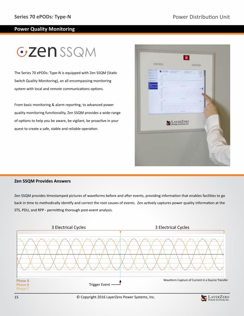
The Series 70 ePODs: Type-N is equipped with Zen SSQM (Static
Switch Quality Monitoring), an all encompassing monitoring
system with local and remote communications options.
From basic monitoring & alarm reporting, to advanced power
quality monitoring functionality, Zen SSQM provides a wide-range
of options to help you be aware, be vigilant, be proactive in your
quest to create a safe, stable and reliable operation.
Zen SSQM Provides Answers
Zen SSQM provides timestamped pictures of waveforms before and after events, providing information that enables facilities to go
back in time to methodically identify and correct the root causes of events. Zen actively captures power quality information at the
STS, PDU, and RPP - permitting thorough post-event analysis.
Product Name: Series 70 ePODs: Type-PUnit Name: 500 + 1000 turn CTsSerial #: 10028-34
Capture Reason: SQ Xfer 0-1Captured By: scb122Capture Time: 01-04-2016 6:53:08 PMMicroticks: 1449941
Phase APhase BPhase CPhase NPhase G
Source 1 Volts L-L
Milliseconds
Volts 0 -200
200
-400
400
-600
600
-800
800
-1000
1000
Source 2 Volts L-L
Milliseconds
Volts 0 -200
200
-400
400
-600
600
-800
800
-1000
1000
Load Volts L-L
Milliseconds
Volts 0 -200
200
-400
400
-600
600
-800
800
-1000
1000
Source 1 Amps
Milliseconds
Amperes
0 -100
100
-200
200
-300
300
-400
400
-500
500
-600
600
-700
700
-800
800
Source 2 Amps
Milliseconds
Amperes
0 -100
100
-200
200
-300
300
-400
400
-500
500
-600
600
-700
700
-800
800
Load Amps
Milliseconds
Amperes
0 -100
100
-200
200
-300
300
-400
400
-500
500
-600
600
-700
700
-800
800
Trigger Event
3 Electrical Cycles 3 Electrical Cycles
Waveform Capture of Current in a Source TransferPhase A Phase BPhase C
Power Distribution Unit Series 70 ePODs: Type-N
15 © Copyright 2016 LayerZero Power Systems, Inc.
Power Quality Monitoring

Subfeeds
A
V
PQ
Current Metering Point
Voltage Metering Point
Power Quality Metering Point
BM Branch Current Monitoring
CB101
Pole 1
CB102
CB201
CB202
CB301
CB302
Pole 2
Pole 1
Pole 2
Pole 1
Pole 2
Power Distribution Unit Series 70 ePODs: Type-N
16 © Copyright 2016 LayerZero Power Systems, Inc.
Power Quality Monitoring

Zen SSQM Parameters Mains Subfeeds or Branch Circuits
Voltage Inputs and Output
Voltage
Frequency (Hertz)
Phase Rotation
Current Inputs
Current (Amps)
Current Fraction of Rating (Percent)
Current Imbalance (Percent)
Real Power (kilowatts)
Apparent Power (kilovolt-amperes)
Reactive Power (kilovolt-amperes reactive)
Power Factor
K Factor
Crest Factor
Alarms
Summary Alarm
Voltage (High, Low)
Overload
Thermostat (High, Low)
THD Over Limit
Frequency (Over, Under)
I A/B/C K-Factor Over Limit
Average K-Factor Over Limit
Incorrect Phase Rotation
Voltage Failure
I G1/G2 Over Ground Fault Limit
I G1/G2 Over Ground Overcurrent Limit
TVSS 1/2/3/4 Failure
Power Distribution Unit Series 70 ePODs: Type-N
17 © Copyright 2016 LayerZero Power Systems, Inc.
Technical Specifications
All product specifications are subject to change without notice.

ePODs: Type-N Models with Withstand Ratings
120/208 V 480 V; 480/277 V; 415/240 V; 400/230 V; 380/220 V 600 V; 575 V
150 A 200kAIC; 150kAIC; 100kAIC; 65kAIC 150kAIC; 100kAIC; 65kAIC; 35kAIC; 25kAIC
100kAIC; 65kAIC; 35kAIC; 25kAIC; 18kAIC
225 A 150kAIC; 100kAIC; 65kAIC 65kAIC; 50kAIC; 25kAIC
250 A200kAIC; 150kAIC; 100kAIC; 65kAIC 150kAIC; 100kAIC; 65kAIC; 35kAIC;
25kAIC100kAIC; 65kAIC; 35kAIC; 25kAIC;
18kAIC400 A600 A800 A 200kAIC; 100kAIC; 65kAIC 100kAIC; 65kAIC; 50kAIC; 35kAIC 42kAIC; 35kAIC; 25kAIC; 20kAIC1000 A
150kAIC; 100kAIC; 65kAIC 100kAIC; 65kAIC; 50kAIC 65kAIC; 50kAIC; 25kAIC1200 A
Mechanical Characteristics 150 A - 250 A 400 A 600 A 800 A 1200 A
Dimensions 60”W x 36”D x 86”H (1524 mm x 914 mm x 2032 mm)
70”W x 36”D x 86”H(1778 mm x 914 mm x
2032 mm)
108”W x 48”D x 90”H(2743 mm x 1219 mm
x 2286 mm)Heat Dissipation 4,750 BTU/Hr 7,000 BTU/Hr 9,500 BTU/Hr 12,500 BTU/Hr 24,000 BTU/HrWeight 1,900 lbs
(862 kg)1,950 lbs (885 kg)
2,000 lbs(907 kg)
2,500 lbs(1134 kg)
6,050 lbs(2744 kg)
Frame Construction Welded FrameElectrical Connections Flexible Laminated Bus, Silver-Plated Solid BusbarColor Textured Powder Coat White (RAL 7035), Blue (RAL 5017), Black, Custom Seismic Floor Anchors Optional Seismic Floor Stand Optional Sectionalization Engineered Composite Insulation, Dead Front Doors
Electrical CharacteristicsStatic Transfer SwitchNumber of Inputs 2, 3 (3 Optional)Frequency 50 Hz, 60 HzPoles 3-pole, 4-pole Phases 3 Phase, 3 Wire, 4 Wire + Ground Neutral Rating 100%, 150%, 200%Transfer Time Nominal 1/4- cycle for in-phase sources Redundancy Single Module Redundancy, Triple Modular Redundancy Optional Circuit Breaker Type Molded Case Switch (Standard), Electronic Trip (Optional)
Circuit Breaker Mounting Type Plug-In Subfeed Distribution Distribution SafePanel™ Distribution
Power Distribution Unit Series 70 ePODs: Type-N
18 © Copyright 2016 LayerZero Power Systems, Inc.
Technical Specifications
All product specifications are subject to change without notice.

Power Quality Monitoring Power Quality Monitoring Technology Zen SSQM™ (Static Switch Quality Monitoring)Waveform Capture Local Display, Remote Display via Web Browser, Waveforms Automatically Emailed Voltmeter Input sources and Output, for each phaseAmmeter Input sources and Output, for each phaseFrequency Meter Both SourcesReal-Time Synchroscope Phase Angle Meter Between SourcesMetering Apparent Power, Real Power, Power Factor, Output Total Harmonic DistortionTime Stamped Transfer Count From First Day Use, From Last ResetCB Status Indicator Open/Closed/Tripped Circuit BreakerSource Indicator Preferred SourcePhase Indicator When Any Two Sources Are Within WindowPower Path Indicator On Live Mimic
Operational CharacteristicsTransfer Modes Automatic; Manual (via Preferred Source Selection)
Inrush Mitigation Technology Patented Dynamic Phase Compensation Algorithm (U.S. Patent 7,589,438 B2)
Password Protection User Configurable Roles
Cooling Convection Cooling
Cable Access Top/Bottom
Service Access Front Only
Bypass Interlock Mechanism Mechanical
Noise & Interference Isolation Optical Fiber in Critical Control Paths
IR Scan Port Type InSight™ IR Portholes
SCR Type Puck
Display Type 15” Color Touch Screen
Display Resolution 1024x768
Bypass Assistance Voice-Guided Bypass
Audio Bezel-Mounted Stereo Speakers
Languages English, French
Mimic Panel Digital
Setpoints Control Digital
Power Supplies Redundant
Connectivity Meters Local Display, Ethernet, Modbus/TCP, http via Web Browser (Non-Proprietary)
Alarms Local Display, Ethernet, Modbus/TCP, http via Web Browser (Non-Proprietary)
Summary Alarm Dry Contacts
Waveforms Local Display, Ethernet, http via Web Browser (Non-Proprietary)
History/Event Log Local Display, Ethernet, http via Web Browser (Non-Proprietary)
Diagnostics Local Display, Ethernet, http via Web Browser (Non-Proprietary)
Time Synchronization Network Time Protocol (NTP)
Power Distribution Unit Series 70 ePODs: Type-N
19 © Copyright 2016 LayerZero Power Systems, Inc.
Technical Specifications
All product specifications are subject to change without notice.

Standards Conformance: Static Transfer Switch UL ETL Listed to UL 1008S
CSA ETL Listed to C22.22 No 107.
Standards Conformance: SafePanel Distribution UL ETL Listed to UL 60950
CSA C22.2 No 29-M1989
Number of Output Circuit Breakers Number of Available SafePanel™ Slots 36
CB Rating Number of Slots Required
100 AF 2
250 AF 3
400 AF 3
400 AF 100% 6
800 AF 6
36 Total Available Slots
1 Slot2 Slots
3 Slots
6 Slots
Universal Dead Front SafePanel™ Panel Board
Interchangeable Plates Fit All CB Sizes
Blank Plates
Power Distribution Unit Series 70 ePODs: Type-N
20 © Copyright 2016 LayerZero Power Systems, Inc.

LayerZero Power Systems, Inc. 1500 Danner Drive
Aurora, OH 44202 U.S.A.
© 2016 LayerZero Power Systems, Inc.
LayerZero Power Systems, LayerZero.com and the LayerZero logo are registered trademark of LayerZero. All product specifications are subject to change without notice.
Learn more at www.LayerZero.com
Rev. 7/16 #16


