Page 1
8/16/2019 LE-EN-55705-0816
http://slidepdf.com/reader/full/le-en-55705-0816 1/71
Slide 1 of 71©2012, 2015 ∙ Table of Contents
• About the Instructor • About the Sponsor • Ask an Expert
STARTSTARTSTARTSTARTSTART
START
This Online Learning Seminar is
available through a professional
courtesy provided by:
Legrand HQ60 Woodlawn Street
West Hartford, CT 06110
Toll-Free:1-877-295-3472
Web: www.legrand.us
powered by
©2012, 2015 Legrand. The material contained in this course was researched, assembled, and produced by
Legrand and remains its property. Questions or concerns about the content of this course should be directedto the program instructor. This multimedia product is the copyright of AEC Daily.
Electrical evice Safety
Page 2
8/16/2019 LE-EN-55705-0816
http://slidepdf.com/reader/full/le-en-55705-0816 2/71
Slide 2 of 71©2012, 2015 ∙ Table of Contents
• About the Instructor • About the Sponsor • Ask an Expert
Electrical Device Safety
Presented By: Legrand Pass and Seymour
50 Boyd Ave
Syracuse, NY 13209
Description: Provides an overview of electrical devices and the safety issues associated with them. Thecourse includes discussions on the features of duplex receptacles, hospital grade receptacles, GFCIs
and other electrical devices, and also discusses updated UL requirements and NEC codes.
To ensure the accuracy of this program material, this course is valid only when listed on AEC Daily’sOnline Learning Center. Please click here to verify the status of this course.
If the course is not displayed on the above page, it is no longer offered.
This course is approved by other organizations. Please click here for details.
The American Institute of Architects · Course No. AEC557 · This program qualifies for 1.0 LU/HSW Hour.
AEC Daily Corporation is a Registered Provider with The American Institute of Architects Continuing Education Systems (AIA/CES). Credit(s)earned on completion of this program will be reported to AIA/CES for AIA members. Certificates of Completion for both AIA members and non-
AIA members are available upon request. This program is registered with AIA/CES for continuing professional education. As such, it does not
include content that may be deemed or construed to be an approval or endorsement by the AIA of any material of construction or any method
or manner of handling, using, distributing, or dealing in any material or product. Questions related to specific materials, methods, and services
will be addressed at the conclusion of this presentation.
Page 3
8/16/2019 LE-EN-55705-0816
http://slidepdf.com/reader/full/le-en-55705-0816 3/71
Slide 3 of 71©2012, 2015 ∙ Table of Contents
• About the Instructor • About the Sponsor • Ask an Expert
AEC Daily Corporation has met the standards and requirements of
the Registered Continuing Education Program. Credit earned on
completion of this program will be reported to RCEP at RCEP.net. A certificate of completion will be issued to each participant. As
such, it does not include content that may be deemed or construed
to be an approval or endorsement by the RCEP.
Page 4
8/16/2019 LE-EN-55705-0816
http://slidepdf.com/reader/full/le-en-55705-0816 4/71
Slide 4 of 71©2012, 2015 ∙ Table of Contents
• About the Instructor • About the Sponsor • Ask an Expert
Purpose and Learning Objectives
Purpose: Provides an overview of electrical devices and the safety issues associated with
them. The course includes discussions on the features of duplex receptacles, hospital
grade receptacles, GFCIs and other electrical devices, and also discusses updated UL
requirements and NEC codes.
Learning Objectives:
At the end of this program, participants will be able to:
• identify the risks associated with electrical receptacles, and specify the appropriate
receptacle to meet the project requirements
• discuss three separate testing standards and the tests associated with each of thesestandards, and relate these to product specification
• list the features to look for in duplex receptacles and hospital grade receptacles,
including special requirements to meet project needs and ensure safety, and
• describe GFCI devices and their features, and explain the updated UL certification tests
that they must comply with.
Page 5
8/16/2019 LE-EN-55705-0816
http://slidepdf.com/reader/full/le-en-55705-0816 5/71
Slide 5 of 71©2012, 2015 ∙ Table of Contents
• About the Instructor • About the Sponsor • Ask an Expert
How to Use This Online Learning Course
• To view this course, use the arrows at the bottom of each slide or the up and down
arrow keys on your keyboard.
• To print or exit the course at any time, press the ESC key on your keyboard. This willminimize the full-screen presentation and display the menu bar.
• Within this course is an exam password that you will be required to enter in order to
proceed with the online examination. Please be sure to remember or write down thisexam password so that you have it available for the test.
• To receive a certificate indicating course completion, refer to the instructions at the end
of the course.
• For additional information and post-seminar assistance, click on any of the logos and
icons within a page or any of the links at the top of each page.
Page 6
8/16/2019 LE-EN-55705-0816
http://slidepdf.com/reader/full/le-en-55705-0816 6/71
Slide 6 of 71©2012, 2015 ∙ Table of Contents
• About the Instructor • About the Sponsor • Ask an Expert
Table of Contents
Importance of Electrical Devices 7
Duplex Receptacles 12
Hospital Grade Devices 22
Ground Fault Circuit Interrupter (GFCI) Devices 34
Other Electrical Devices 55
Connected Equipment Safety Options 66
Click on title to view
Page 7
8/16/2019 LE-EN-55705-0816
http://slidepdf.com/reader/full/le-en-55705-0816 7/71
Slide 7 of 71©2012, 2015 ∙ Table of Contents
• About the Instructor • About the Sponsor • Ask an Expert
Importance of Electrical Devices
Page 8
8/16/2019 LE-EN-55705-0816
http://slidepdf.com/reader/full/le-en-55705-0816 8/71
Slide 8 of 71©2012, 2015 ∙ Table of Contents
• About the Instructor • About the Sponsor • Ask an Expert
The Importance of Electrical Devices
Question. Answer .
What utility, found in most buildings,represents the greatest risk for harm to
humans by contact?
Electricity.
What is the most common point of contactwith the electrical system by people in
close proximity to live parts?
Electrical devices, primarily receptacleswhich will be the focus of this program.
What is the most common cause ofelectrocution? Contact with live parts.
What is a common listed cause of building
structure fires?
Electrical fires.
Page 9
8/16/2019 LE-EN-55705-0816
http://slidepdf.com/reader/full/le-en-55705-0816 9/71
Slide 9 of 71©2012, 2015 ∙ Table of Contents
• About the Instructor • About the Sponsor • Ask an Expert
The Importance of Electrical Devices
Question. Answer .
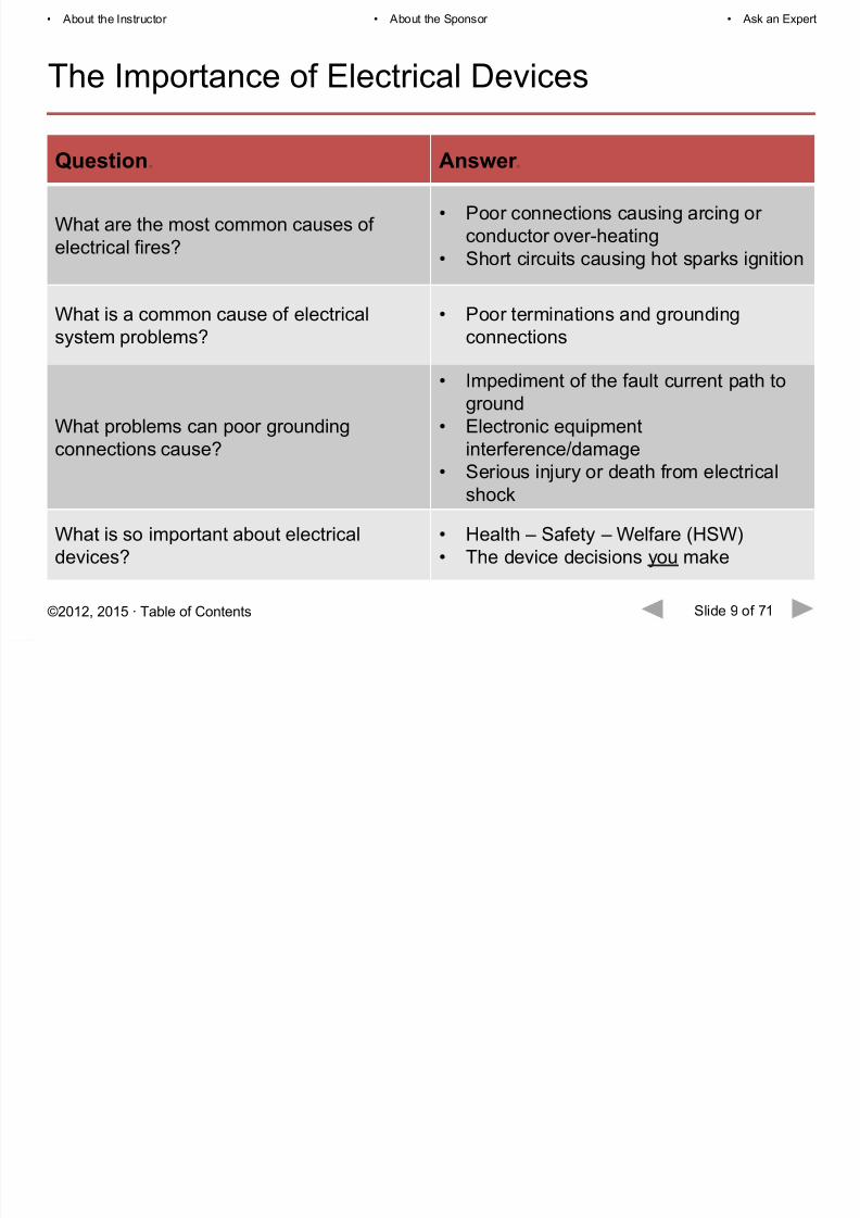
What are the most common causes ofelectrical fires?
• Poor connections causing arcing or
conductor over-heating
• Short circuits causing hot sparks ignition
What is a common cause of electrical
system problems?
• Poor terminations and grounding
connections
What problems can poor grounding
connections cause?
• Impediment of the fault current path to
ground
• Electronic equipment
interference/damage• Serious injury or death from electrical
shock
What is so important about electrical
devices?
• Health – Safety – Welfare (HSW)
• The device decisions you make
Page 10
8/16/2019 LE-EN-55705-0816
http://slidepdf.com/reader/full/le-en-55705-0816 10/71
Slide 10 of 71©2012, 2015 ∙ Table of Contents
• About the Instructor • About the Sponsor • Ask an Expert
Receptacle Classifications
There are three separate testing standards—independent of one another.
UL is the most common standard of testing, and it is important to specify receptacles and
switches that are UL compliant.
Some manufacturers take an extra measure and put their devices through Fed Spec
testing, which means the products are put through a separate, more rigorous testing
standard. In the chart on the following slide, some of the tests that are not performed withUL but are performed through Fed Spec are highlighted in red.
Hospital grade testing is performed by UL and consists of specific testing standards that
ensure a redundant ground in very rigorous situations. All of the tests are to ensure safety
measures, but hospital grade testing is performed in addition to UL or Fed Spec.
With all the device “grades” available, choice is important. Write your Master Spec around
the specific key features and quality you want, then hold to it.
Page 11
8/16/2019 LE-EN-55705-0816
http://slidepdf.com/reader/full/le-en-55705-0816 11/71
Slide 11 of 71©2012, 2015 ∙ Table of Contents
• About the Instructor • About the Sponsor • Ask an Expert
Receptacle Classifications
Standard Grade/General Use
Performance Test Sequence.
Additional Tests Required
for Fed Spec.
Additional Tests Required
for Hospital Grade.
Blade retention.Gripping – power blade and grounding
blade . Abrupt plug removal.
Terminal strength. Terminal strength. Grounding contact temperature.
Overload. Overload – 200% ac. Grounding contact resistance.
Temperature rise. Temperature rise. Grounding contact overstress.
Repeat blade retention. Repeat blade retention. Additional terminal strength.
Resistance to arcing. Dielectric voltage withstand. Assembly security.
Grounding pin retention. Insulation resistance. Impact.
Fault current. Heat resistance. Increased mold stress relief .
Dielectric voltage withstand. Assembly security.
Mold stress relief .
Dielectric voltage withstand (repeated)
Assembly security.
Page 12
8/16/2019 LE-EN-55705-0816
http://slidepdf.com/reader/full/le-en-55705-0816 12/71
Slide 12 of 71©2012, 2015 ∙ Table of Contents
• About the Instructor • About the Sponsor • Ask an Expert
Duplex Receptacles
Page 13
8/16/2019 LE-EN-55705-0816
http://slidepdf.com/reader/full/le-en-55705-0816 13/71
Slide 13 of 71©2012, 2015 ∙ Table of Contents
• About the Instructor • About the Sponsor • Ask an Expert
Features To Look For
Page 14
8/16/2019 LE-EN-55705-0816
http://slidepdf.com/reader/full/le-en-55705-0816 14/71
Slide 14 of 71©2012, 2015 ∙ Table of Contents
• About the Instructor • About the Sponsor • Ask an Expert
Features To Look For
• One-piece, brass wrap-around strap
• locking “fingers” into the device back
body and face
• integral ground contacts
The one-piece, brass wrap-around strap provides
strength and better conductivity in a “uniground”
assembly.
• Drive screws in addition to the locking fingers
that lock the strap into device face and body
This prevents the strap from separating from the
face and back body and exposing live parts.
Page 15
8/16/2019 LE-EN-55705-0816
http://slidepdf.com/reader/full/le-en-55705-0816 15/71
Slide 15 of 71©2012, 2015 ∙ Table of Contents
• About the Instructor • About the Sponsor • Ask an Expert
Features To Look For
• Self-grounding device mounting screw
Self-grounding mounting screws ensure a solid
connection to ground without needing to install agrounding jumper to the box from the device in the
absence of a grounding conductor.
• Tri-drive head terminal and ground terminal
screws
Tri-drive head terminal screws accept Robertson,
Phillips, and standard straight blade screwdrivers—this facilitates a better termination.
Page 16
8/16/2019 LE-EN-55705-0816
http://slidepdf.com/reader/full/le-en-55705-0816 16/71
Slide 16 of 71©2012, 2015 ∙ Table of Contents
• About the Instructor • About the Sponsor • Ask an Expert
Features To Look For
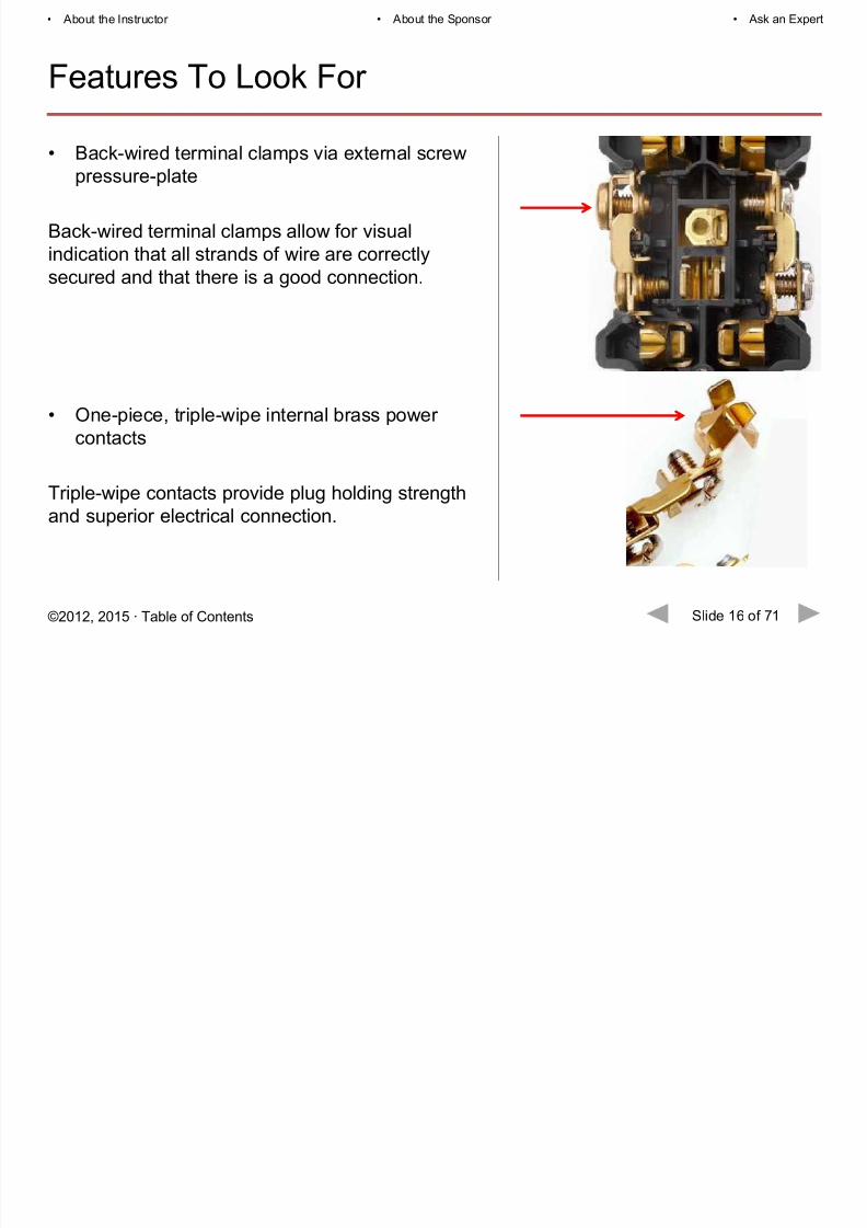
• Back-wired terminal clamps via external screw
pressure-plate
Back-wired terminal clamps allow for visualindication that all strands of wire are correctly
secured and that there is a good connection.
• One-piece, triple-wipe internal brass power
contacts
Triple-wipe contacts provide plug holding strength
and superior electrical connection.
Page 17
8/16/2019 LE-EN-55705-0816
http://slidepdf.com/reader/full/le-en-55705-0816 17/71
Slide 17 of 71©2012, 2015 ∙ Table of Contents
• About the Instructor • About the Sponsor • Ask an Expert
Special Requirements: Tamper-Resistant
• Tamper-Resistant
Child safety presents a major concern for electrical manufacturers, and Tamper-Resistant
receptacles have long been considered the most reliable means of protection. The 2014NEC Code continues to add and revise current standards that include, but are not limited
to, all 15- and 20-amp, 125-volt receptacles to be placed in all pediatric care areas,
dwelling locations, childcare facilities, guest rooms, guest suites, etc. Some of these Codes
have section revisions to accommodate exception changes.
A mechanical shutter that will not open unless a proper plug is used:
Thermoplastic shutter in
closed position covers access
to contacts.
Insertion of object in any one
side does not open shutter.
Two-bladed plug or grounding
plug compresses spring and
simultaneously opens bothshutters.
Page 18
8/16/2019 LE-EN-55705-0816
http://slidepdf.com/reader/full/le-en-55705-0816 18/71
Slide 18 of 71©2012, 2015 ∙ Table of Contents
• About the Instructor • About the Sponsor • Ask an Expert
Special Requirements: Tamper-Resistant
• 2005 NEC Section 517.18 (c): TR receptacles required in all pediatric care areas.
• 2008 NEC Section 406.11: TR receptacles required in all dwelling locations.
• 2011 NEC Section 404.4 (D)(5): TR receptacles required to be installed wherever areceptacle is replaced in areas that are required to be TR by code.
• 2011 NEC Section 406.12, 13 & 14: TR receptacles required in childcare facilities,
guest rooms, guest suites, and specified dwelling areas.
Tamper-Resistant receptacles have been required in pediatric care areas for years. The
importance of TR receptacles came about with the NEC Code in 2005, where TR
receptacles became a requirement in all pediatric care areas. It was expanded in 2008 with
the requirement to include them in all dwelling locations, including residential housing (that
was modified in 2011 to exclude any receptacle 5½ feet above the floor or higher). In 2011,the requirement was expanded to include childcare facilities, guest room suites, and any
other area identified as a dwelling location.
Page 19
8/16/2019 LE-EN-55705-0816
http://slidepdf.com/reader/full/le-en-55705-0816 19/71
Slide 19 of 71©2012, 2015 ∙ Table of Contents
• About the Instructor • About the Sponsor • Ask an Expert
Special Requirements: Tamper-Resistant
• Code Requirements:
• dwelling units and pediatric care areas
• Specification Applications:
• Fed Spec Tamper-Resistant:
• grade schools, daycares, barracks,
dorm rooms
Page 20
8/16/2019 LE-EN-55705-0816
http://slidepdf.com/reader/full/le-en-55705-0816 20/71
S
Page 21
8/16/2019 LE-EN-55705-0816
http://slidepdf.com/reader/full/le-en-55705-0816 21/71
Slide 21 of 71©2012, 2015 ∙ Table of Contents
• About the Instructor • About the Sponsor • Ask an Expert
Special Requirements: Isolated Ground
Providing a separate “clean” ground path to the main service
ground reduces electrical noise (EMI) from being conducted
to sensitive electronic equipment and corrupting data, or
causing malfunctions of critical equipment and life-safetysystems.
Orange
triangle
denotes“isolated
ground”
Ab t th I t t Ab t th S A k E t
Page 22
8/16/2019 LE-EN-55705-0816
http://slidepdf.com/reader/full/le-en-55705-0816 22/71
Slide 22 of 71©2012, 2015 ∙ Table of Contents
• About the Instructor • About the Sponsor • Ask an Expert
Hospital Grade Devices
Ab t th I t t Ab t th S A k E t
Page 23
8/16/2019 LE-EN-55705-0816
http://slidepdf.com/reader/full/le-en-55705-0816 23/71
Slide 23 of 71©2012, 2015 ∙ Table of Contents
• About the Instructor • About the Sponsor • Ask an Expert
Special Requirements: Hospital Grade
• Hospital grade – “green dot”
Receptacle devices must pass several additional UL 498 test
requirements to be listed as hospital grade and bear the greendot on the device face.
Hospital grade devices are required by UL to withstand
significantly higher levels of abuse and the additional life-safety
considerations in healthcare facilities.
Additional UL 498 test requirements include a demonstrated
ability to withstand severe abuse and continue to maintain:
• assembly integrity (no exposed live parts)
• power blade retention (continuity of service when a patient
needs it), and
• grounding pin retention (ensures grounding continuity for
equipment in contact with patients).
Abo t the Instr ctor About the Sponsor Ask an Expert
Page 24
8/16/2019 LE-EN-55705-0816
http://slidepdf.com/reader/full/le-en-55705-0816 24/71
Slide 24 of 71©2012, 2015 ∙ Table of Contents
• About the Instructor • About the Sponsor • Ask an Expert
Special Requirements: Hospital Grade
• Hospital grade – illuminated face
This is an extended service LED version with an illuminated
face. An LED (light emitting diode) illuminated face generally has10–12 years of life, offering long service and reduced
maintenance.
The benefit is that they are easy to find in darkened rooms of
24/7 healthcare facilities.
They are often installed on emergency, critical care, and life
support circuits to locate receptacles during power outages and
emergency conditions.
• About the Instructor • About the Sponsor • Ask an Expert
Page 25
8/16/2019 LE-EN-55705-0816
http://slidepdf.com/reader/full/le-en-55705-0816 25/71
Slide 25 of 71©2012, 2015 ∙ Table of Contents
• About the Instructor • About the Sponsor • Ask an Expert
Special Requirements: Hospital Grade
• Hospital grade – write-on label
A write-on label for recording circuit designation is used to
indicate the circuit on which the receptacle is wired, even if theplate is removed, so power to the correct circuit can be easily
shut off.
The plates may be removed for repainting walls, receptacle
replacement, or troubleshooting.
• About the Instructor • About the Sponsor • Ask an Expert
Page 26
8/16/2019 LE-EN-55705-0816
http://slidepdf.com/reader/full/le-en-55705-0816 26/71
Slide 26 of 71©2012, 2015 ∙ Table of Contents
• About the Instructor • About the Sponsor • Ask an Expert
Special Requirements: Hospital Grade
• Hospital grade – minimum number required
The hospital grade receptacles required by 517.18(B) are
permitted to be of the single, duplex, or quadruplex type orany combination of the three that add up to at least the
minimum of eight receptacles required. In critical care areas
per 517.19(B), each patient bed location should be provided
with a minimum of 14 receptacles. These receptacles shall
be either single, duplex, or quadruplex type, or anycombination of the three. In operating rooms, per 517.19(C),
a minimum of 36 receptacles are required and shall be
single or duplex types, or a combination of both. The
grounding terminals of the hospital grade receptacles must
be connected to an insulated copper equipment-groundingconductor of the branch circuits required by 517.13(B).
• About the Instructor • About the Sponsor • Ask an Expert
Page 27
8/16/2019 LE-EN-55705-0816
http://slidepdf.com/reader/full/le-en-55705-0816 27/71
Slide 27 of 71©2012, 2015 ∙ Table of Contents
• About the Instructor • About the Sponsor • Ask an Expert
Hospital Grade Receptacles
UL Hospital Grade Testing for Receptacles
• Abrupt Removal Test
– 10 lbs. down by excessive force• Ground Contact / Overstress Test
– 4 oz. minimum retention
• Impact Test
– 5 lbs. weight onto center of device• Assembly Security Test
– 100 lbs. support test
Hospital grade receptacles go through strenuous procedures and testing. The testing isabove and beyond the standard UL and Fed Spec testing. The key point for a hospital
grade receptacle is excessive redundant ground capabilities that offer the highest level of
safety.
• About the Instructor • About the Sponsor • Ask an Expert
Page 28
8/16/2019 LE-EN-55705-0816
http://slidepdf.com/reader/full/le-en-55705-0816 28/71
Slide 28 of 71©2012, 2015 ∙ Table of Contents
• About the Instructor • About the Sponsor • Ask an Expert
Hospital Grade Receptacles
Abrupt Removal Test
After ten conditioning insertion and withdrawal
cycles of an attachment plug of matchingconfiguration and ground pin, each outlet is to
hold, without any displacement, a fully inserted
test pin for at least one minute from a facedown,
horizontal position. Then, each receptacle is
mounted to represent a typical installation andgoes through a series of abrupt removal tests—
the full insertion of a test plug that is removed by
dropping an attached 10-pound weight two feet,
thus exerting excessive force on the receptacle
face and contacts. Each outlet must go througheight cycles of this test. The outlet must have no
breakage that would interfere with its function and
integrity.
• About the Instructor • About the Sponsor • Ask an Expert
Page 29
8/16/2019 LE-EN-55705-0816
http://slidepdf.com/reader/full/le-en-55705-0816 29/71
Slide 29 of 71©2012, 2015 ∙ Table of Contents
About the Instructor About the Sponsor Ask an Expert
Hospital Grade Receptacles
Ground Contact / Overstress Test
The receptacle ground contact is conditioned with
twenty cycles of full insertion and withdrawal of a.204" oversized test pin. Then, with the receptacle
in a horizontal, facedown position, the same
contact must retain a .184" diameter 4-ounce test
pin for at least one minute without any
displacement.
• About the Instructor • About the Sponsor • Ask an Expert
Page 30
8/16/2019 LE-EN-55705-0816
http://slidepdf.com/reader/full/le-en-55705-0816 30/71
Slide 30 of 71©2012, 2015 ∙ Table of Contents
About the Instructor About the Sponsor Ask an Expert
Hospital Grade Receptacles
Impact Test
Receptacles mounted in a cast metal box are
placed on a steel plate facing upward. A 5-poundweight is dropped from 18" above the device
impacting at the center of the outlet. The device
must withstand the impact without having any
breakage that hinders its function.
• About the Instructor • About the Sponsor • Ask an Expert
Page 31
8/16/2019 LE-EN-55705-0816
http://slidepdf.com/reader/full/le-en-55705-0816 31/71
Slide 31 of 71©2012, 2015 ∙ Table of Contents
About the Instructor About the Sponsor Ask an Expert
Hospital Grade Receptacles
Assembly Security Test
A device, supported at its mounting screws, must
withstand 100 pounds through the slots in thereceptacle face without cracking the device back-
body or deforming the yoke.
• About the Instructor • About the Sponsor • Ask an Expert
Page 32
8/16/2019 LE-EN-55705-0816
http://slidepdf.com/reader/full/le-en-55705-0816 32/71
Slide 32 of 71©2012, 2015 ∙ Table of Contents
p p
Hospital Grade Plugs and Connectors
Hospital grade plugs and connectors are tested
to the demanding requirements of UL 498
(similar to hospital grade receptacles).
These requirements cover attachment plugs,
receptacles, cord connectors, inlets, current taps
provided with wiring terminals for flexible cord,
and flatiron and appliance plugs—all intended
for connection to a branch circuit for use inaccordance with the National Electrical Code,
ANSI/NFPA 70.
Specifications for “hospital grade” connectors
appear in UL498-2001, Supplement SD.
• About the Instructor • About the Sponsor • Ask an Expert
Page 33
8/16/2019 LE-EN-55705-0816
http://slidepdf.com/reader/full/le-en-55705-0816 33/71
Slide 33 of 71©2012, 2015 ∙ Table of Contents
p p
Hospital Grade Testing
Dependable device solutions are required in the most critical health care applications.
• Reliable power quality is required by sensitive equipment, under repetitive abuse.
• Dependable ground continuity of wiring devices protects both personnel and patients
from compromised electrical connections.• Corrosion resistance is a necessary feature where frequent wash downs result in
excess moisture that can compromise performance.
• Replacement of wiring devices must be quick and easy.
Crush Test - A wired plug or connector isplaced between two steel plates andsubjected to a force which is steadilyincreased to 500 pounds. “There shall be nobreakage, deformation or other effect thatmay interfere with the function of the device.”
Drop Test - A sample wired plug or connector issuspended horizontally by its attached cord, andreleased so that it impacts a hard wood surface45 inches below the point of suspension &repeated for 1300 cycles. “There shall be nobreakage, deformation, or other damage whichwould interfere with the functioning of the device.”
Pull Test - The cord must remain securely fastenedafter straight pulls of 30 lbs. and rotating pulls (in a 3-inch circle) of 10 lbs. for two hours. “Displacement ofconductors, insulation, and outer jacket of the flexiblecord shall not exceed 1/32 inch. There shall be nocuts, rips, or tears in cord insulation. “Heavy-dutycord stress is typical abuse for industrial plugs andconnectors.”
• About the Instructor • About the Sponsor • Ask an Expert
Page 34
8/16/2019 LE-EN-55705-0816
http://slidepdf.com/reader/full/le-en-55705-0816 34/71
Slide 34 of 71©2012, 2015 ∙ Table of Contents
p p
Ground Fault Circuit Interrupter (GFCI) Devices
• About the Instructor • About the Sponsor • Ask an Expert
Page 35
8/16/2019 LE-EN-55705-0816
http://slidepdf.com/reader/full/le-en-55705-0816 35/71
Slide 35 of 71©2012, 2015 ∙ Table of Contents
What Is a GFCI?
The National Electric Code 2005 Edition Article 100 defines a
GFCI:
“A ground fault circuit interrupter (GFCI) is a device intended
for the protection of personnel that functions to de-energize acircuit or portion thereof within an established period of time
when a current to ground exceeds the values established for a
Class A device.”
Class A ground fault circuit interrupters trip when the current toground has a value in the range of 4 mA to 6 mA.
GFCIs protect against electric shock incidents, including death
by electrocution.
• About the Instructor • About the Sponsor • Ask an Expert
Page 36
8/16/2019 LE-EN-55705-0816
http://slidepdf.com/reader/full/le-en-55705-0816 36/71
Slide 36 of 71©2012, 2015 ∙ Table of Contents
How a GFCI Works
A GFCI has an internal comparator
circuit that monitors the difference in
current between the hot and neutral on
the load side of the device. If thecomparator circuit senses a difference
between the hot and neutral of 5 mAs, it
will interrupt power to the load side of
the receptacle in .025 seconds—
preventing a serious injury due toelectric shock.
Normal
Conditions.
Hazardous
Ground Fault.
GFCI
Protected.
• About the Instructor • About the Sponsor • Ask an Expert
Page 37
8/16/2019 LE-EN-55705-0816
http://slidepdf.com/reader/full/le-en-55705-0816 37/71
Slide 37 of 71©2012, 2015 ∙ Table of Contents
How a GFCI Works
The diagram shows the dangers of
electrical current. Less than 20 mA will
affect respiration. It only takes 50 mA to
cause heart fibrillation. The GFCI isengineered to trip at about 5 mA, a level
below that which would injure a healthy
person.
• About the Instructor • About the Sponsor • Ask an Expert
Page 38
8/16/2019 LE-EN-55705-0816
http://slidepdf.com/reader/full/le-en-55705-0816 38/71
Slide 38 of 71©2012, 2015 ∙ Table of Contents
How a GFCI Works
Because a GFCI constantly monitors the hot and neutral conductors only, a ground
conductor is not required for the device to function properly. This allows GFCIs to be used
in retrofit applications in older houses with two-wire (non-grounded) wiring.
Receptacle-type GFCI’s switch both the ungrounded conductor and neutral.
• About the Instructor • About the Sponsor • Ask an Expert
Page 39
8/16/2019 LE-EN-55705-0816
http://slidepdf.com/reader/full/le-en-55705-0816 39/71
Slide 39 of 71©2012, 2015 ∙ Table of Contents
Electrocution Data
Note the significant electrocution decline represented by the red line. In the mid 1970s time
period, there were more than 600 consumer product related electrocutions annually. Today,
there are less than ⅓ that number, in large part due to GFCI receptacle use.
Annual Electrocutions Associated With Consumer Products.
• About the Instructor • About the Sponsor • Ask an Expert
Page 40
8/16/2019 LE-EN-55705-0816
http://slidepdf.com/reader/full/le-en-55705-0816 40/71
Slide 40 of 71©2012, 2015 ∙ Table of Contents
National Electrical Code
Timeline of Primary Requirements
1968 Underwater light fixtures in swimming pools
1971 Construction sites; Outdoors at dwellings
1975 Bathrooms of residential occupancies
1978 Dwelling unit garages; Marinas and boatyards
1981 Within 20 ft. of spas and hot tubs
1987 At least one receptacle in a dwelling basement; Kitchen receptacles within 6 ft. of
sink, above counter tops
1993 Non-dwelling bathrooms and on rooftops
2002 Commercial kitchens
2005 Laundry, utility and wet bar sinks; Non-dwelling outdoor receptacles accessible to
the public
2008 All outdoor receptacles
2011 Within 6 ft. of all sinks in a dwelling; Indoor wet locations in other than dwellings
2014 Within 6 ft. of any bathtub or shower stall; All 125V, 15A or 20A receptacles in
laundry areas in dwellings; Dishwasher outlets in dwellings
• About the Instructor • About the Sponsor • Ask an Expert
Page 41
8/16/2019 LE-EN-55705-0816
http://slidepdf.com/reader/full/le-en-55705-0816 41/71
Slide 41 of 71©2012, 2015 ∙ Table of Contents
Features To Look For
• About the Instructor • About the Sponsor • Ask an Expert
Page 42
8/16/2019 LE-EN-55705-0816
http://slidepdf.com/reader/full/le-en-55705-0816 42/71
Slide 42 of 71©2012, 2015 ∙ Table of Contents
Features To Look For
GFCIs are required by NEC 2011 in facility areas prone to electrical shock such as
kitchens, bathrooms, utility rooms, garages, swimming pools, outdoors, construction sites,
crawl spaces, etc. The NEC continuously updates their codes and adds new locations that
require GFCIs.
UL recommends that installed GFCIs should only be tested with their integral TEST and
RESET buttons.
In addition, UL, NEMA, and OSHA recommend not using external testers because they do
not produce accurate results.
GFCI receptacles manufactured on or after June 29, 2015 will require the self-test (auto-
monitoring) feature.
Source: NFPA 70. “National Electrical Code.” NEC 2005. Copyright © 2005. National Fire Protection Association. All Rights Reserved.
• About the Instructor • About the Sponsor • Ask an Expert
Page 43
8/16/2019 LE-EN-55705-0816
http://slidepdf.com/reader/full/le-en-55705-0816 43/71
Slide 43 of 71©2012, 2015 ∙ Table of Contents
Features To Look For
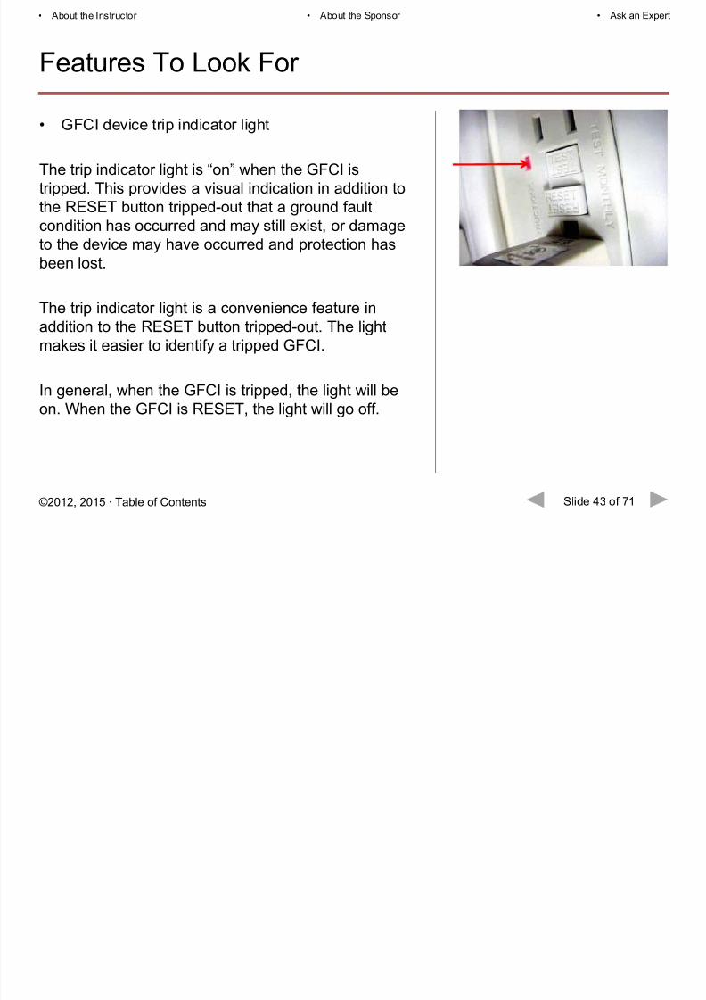
• GFCI device trip indicator light
The trip indicator light is “on” when the GFCI is
tripped. This provides a visual indication in addition tothe RESET button tripped-out that a ground fault
condition has occurred and may still exist, or damage
to the device may have occurred and protection has
been lost.
The trip indicator light is a convenience feature in
addition to the RESET button tripped-out. The light
makes it easier to identify a tripped GFCI.
In general, when the GFCI is tripped, the light will be
on. When the GFCI is RESET, the light will go off.
• About the Instructor • About the Sponsor • Ask an Expert
Page 44
8/16/2019 LE-EN-55705-0816
http://slidepdf.com/reader/full/le-en-55705-0816 44/71
Slide 44 of 71©2012, 2015 ∙ Table of Contents
Features To Look For
• GFCI device “auto-ground” feature
This is an “auto-ground” feature in the strap that assures grounding when the device is
screwed to the metal box. This feature eliminates the need to run a separate equipment-
grounding wire from the metallic box to the GFCI device.This feature ensures proper equipment ground, which helps to prevent electrocution.
• Self-test GFCI devices
A self-test GFCI conducts an automatic test every second, ensuring that it is always readyto protect.
If the device fails the test, the indicator light flashes to signal that the GFCI should be
replaced.
• Hospital grade GFCI devices (green dot)
GFCI devices must meet the same additional test requirements in UL 498 that a receptacle
device must pass to be listed hospital grade and bear the green dot on the device face.
This ensures the GFCI device helps to prevent injury, including electrocution, in healthcare
facilities.
• About the Instructor • About the Sponsor • Ask an Expert
Page 45
8/16/2019 LE-EN-55705-0816
http://slidepdf.com/reader/full/le-en-55705-0816 45/71
Slide 45 of 71©2012, 2015 ∙ Table of Contents
Features To Look For
• Importance of meeting Fed Spec requirements
Federal Specification W-C-596 – General Specification for Electrical Power Connectors
has long been used as the quality standard for commercial receptacles. The document isproduced by the General Service Administration of the U.S. Federal Government and
identifies construction features, marking specifications and performance requirements
beyond the requirements of the safety standards, for the purpose of durability and service
life. Underwriters Laboratories is authorized to apply the federal specification verification
mark, and Fed Spec is required on many government projects.
W-C-596 requires more rigorous abuse and performance tests in:
• Blade retention• Terminal strength
• Current overload
• Temperature rise
• Integrity of assembly• Grounding contact
• Accelerated aging
• And more…
• About the Instructor • About the Sponsor • Ask an Expert
Page 46
8/16/2019 LE-EN-55705-0816
http://slidepdf.com/reader/full/le-en-55705-0816 46/71
Slide 46 of 71©2012, 2015 ∙ Table of Contents
Testing GFCI Receptacles
Test during installation and monthly:
1. Plug lamp into GFCI.
2. Turn on lamp.
3. Push TEST button. GFCI should trip, stopping flow of electricity to the lamp.
The RESET button will pop out.
4. If the lamp does not turn off when the test button is pushed, the GFCI is not working
properly and should be replaced immediately.
5. If the lamp does turn off when the test button is pushed, the GFCI is working properly.
To restore power, press the RESET button.
• About the Instructor • About the Sponsor • Ask an Expert
Page 47
8/16/2019 LE-EN-55705-0816
http://slidepdf.com/reader/full/le-en-55705-0816 47/71
Slide 47 of 71©2012, 2015 ∙ Table of Contents
UL Certification Tests for GFCIs
GFCI receptacle devices must meet these more rigorous, revised UL certification tests for
GFCIs effective July 28, 2006:
End of Life: When a GFCI receptacle is incapable of passing its internal test function (it is
no longer capable of providing ground fault protection), it will comply with either a or b:
a) Render itself incapable of delivering power
b) Indicate by visual and/or audible means that the device must be replaced
Reverse Line-Load Miswire: A GFCI loses its ability to protect when it is miswired (line
wires connected to load terminals and load wires connected to line terminals).
UL requirements to comply with:
a) Yellow warning sticker on load terminals
b) A GFCI will deny power to the receptacle face if it is miswired
• About the Instructor • About the Sponsor • Ask an Expert
Page 48
8/16/2019 LE-EN-55705-0816
http://slidepdf.com/reader/full/le-en-55705-0816 48/71
Slide 48 of 71©2012, 2015 ∙ Table of Contents
UL Certification Tests for GFCIs
GFCIs - Important Safety Warning
ATTENTIONThe load terminals under this label are for feeding additional receptacles. Miswiring can leave this outlet
without ground fault protection. Read instructions prior to wiring.
Miswire label
wrapped around
“load terminals”
• About the Instructor • About the Sponsor • Ask an Expert
Page 49
8/16/2019 LE-EN-55705-0816
http://slidepdf.com/reader/full/le-en-55705-0816 49/71
Slide 49 of 71©2012, 2015 ∙ Table of Contents
Types of GFCIs
15A & 20A GFCI Receptacles. Hospital Grade GFCI
Receptacles .
Meets demanding UL Hospital
Grade requirements.
Tamper-Resistant GFCI
Receptacles.
Shutter system protects children
Required by 2008 NEC in homes.
Dead Front GFCI.
Rated as a 1.5 HP motor control
switch.
Switch / GFCI Receptacles.
Ideal for kitchen and bath
remodeling.
Nightlight / GFCI Receptacles.
LED Nightlight with 20-year life.
Weather-Resistant GFCI
Receptacles.
Required by NEC for outdoor
installations.
• About the Instructor • About the Sponsor • Ask an Expert
Page 50
8/16/2019 LE-EN-55705-0816
http://slidepdf.com/reader/full/le-en-55705-0816 50/71
Slide 50 of 71©2012, 2015 ∙ Table of Contents
Types of GFCIs
Prewired Plugtail GFCI
Receptacle.
Faster, more reliable installation.
NAFTA-Compliant GFCI
Receptacles.
To meet requirements of Buy
American Act .
Isolated Ground GFCI
Receptacles.
For computerized equipment in
commercial kitchens and labs.
RoHS GFCI Receptacles.
Reduction of hazardous
substances.
Portable GFCI.
For construction and
maintenance.
Audible Alarm GFCI
Receptacles.
For refrigerators, freezers, sump
pumps.
• About the Instructor • About the Sponsor • Ask an Expert
Page 51
8/16/2019 LE-EN-55705-0816
http://slidepdf.com/reader/full/le-en-55705-0816 51/71
Slide 51 of 71©2012, 2015 ∙ Table of Contents
GFCI FAQs
Q: Can a GFCI be installed on a two-wire system and will it work
properly?
A: Yes, a GFCI can be installed on a two-wire system, and if a
ground fault should occur, the GFCI will safely remove voltage to the
load. The installation is allowed by the National Electrical Code,
Article 406.4(D)(2)(b). Even in a three-wire system, the GFCI is only
monitoring the hot and the neutral conductors. If a leakage path toground is formed, the path will be between the load and ground or
through the body and ground. At that time, if the leakage is sufficient,
the GFCI will detect the difference between the hot and the neutral
current, and the GFCI will trip.
• About the Instructor • About the Sponsor • Ask an Expert
Page 52
8/16/2019 LE-EN-55705-0816
http://slidepdf.com/reader/full/le-en-55705-0816 52/71
Slide 52 of 71©2012, 2015 ∙ Table of Contents
GFCI FAQs
Q: How many receptacles can be wired downstream from a GFCI?
A: There is no set limit; however, thought should be given to thelength of the wire run. The farther the distance is from the GFCI to
the load, the greater the chance is for nuisance tripping to occur.
Please remember the exam password TRIPPING. You will be required to enter it in
order to proceed with the online examination.
• About the Instructor • About the Sponsor • Ask an Expert
Page 53
8/16/2019 LE-EN-55705-0816
http://slidepdf.com/reader/full/le-en-55705-0816 53/71
Slide 53 of 71©2012, 2015 ∙ Table of Contents
GFCI FAQs
Q: I just installed a GFCI in a facility. I have two receptacles wired to
be protected downstream. When I push the test button, the unit will
trip. The power is removed on the receptacles downstream, but there
is still power on the GFCI. Is the GFCI defective?
A: No, the GFCI is not defective. This question is also a classic. The
GFCI was wired with the line and load conductors in reverse (line-
load miswire). When the test button is pushed, the unit will trip. Ifreceptacles are wired downstream, voltage will be removed to those
devices and power will remain on the GFCI contacts. It is strongly
recommended upon installation of a GFCI to test for voltage at the
contacts after the GFCI has been tripped.
• About the Instructor • About the Sponsor • Ask an Expert
Page 54
8/16/2019 LE-EN-55705-0816
http://slidepdf.com/reader/full/le-en-55705-0816 54/71
Slide 54 of 71©2012, 2015 ∙ Table of Contents
GFCI FAQs
Q: My GFCI has a NEMA 5-15R configuration, but the side of the
device says it is rated for 20-amps. Do I have the proper unit, or is
the device incorrectly marked?
A: The 15-amp GFCI, just like a receptacle, is designed to be
installed on a 15- or 20-amp branch circuit. The 20-amp rating is for
when the device is used in a feed-thru application on a 20-amp
branch circuit. A 15-amp GFCI and a NEMA 5-15R receptacle aretested by UL to confirm the devices are capable of handling the
higher current.
• About the Instructor • About the Sponsor • Ask an Expert
Page 55
8/16/2019 LE-EN-55705-0816
http://slidepdf.com/reader/full/le-en-55705-0816 55/71
Slide 55 of 71©2012, 2015 ∙ Table of Contents
Other Electrical Devices
• About the Instructor • About the Sponsor • Ask an Expert
Page 56
8/16/2019 LE-EN-55705-0816
http://slidepdf.com/reader/full/le-en-55705-0816 56/71
Slide 56 of 71©2012, 2015 ∙ Table of Contents
Weatherproof Covers
Where 15- and 20-amp receptacles are installed outdoors in a wet location, they must be
provided with an enclosure or cover that is weatherproof whether or not the attachment
plug is inserted. [NEC 406.9(B)(1)]
• About the Instructor • About the Sponsor • Ask an Expert
Page 57
8/16/2019 LE-EN-55705-0816
http://slidepdf.com/reader/full/le-en-55705-0816 57/71
Slide 57 of 71©2012, 2015 ∙ Table of Contents
Arc-Fault Circuit Interrupter (AFCI)
AFCI receptacles protect against electrical fires.
NEC definition of AFCI:
A device intended to provide protection from the effects of arc faults by recognizingcharacteristics unique to arcing and by functioning to de-energize the circuit when an arc
fault is detected.
• About the Instructor • About the Sponsor • Ask an Expert
Page 58
8/16/2019 LE-EN-55705-0816
http://slidepdf.com/reader/full/le-en-55705-0816 58/71
Slide 58 of 71©2012, 2015 ∙ Table of Contents
AFCI Receptacle: Types of Arcing
Arcing is current flowing
through an unintended
path.
There are two types of
arcing: parallel and series
(between ends of broken
conductor).
Very high temperature are
possible―10,000 degrees
Fahrenheit ignites studs,
and conductor insulation.
Test lab photo: series arc on
appliance cord resulting in fire.
• About the Instructor • About the Sponsor • Ask an Expert
Page 59
8/16/2019 LE-EN-55705-0816
http://slidepdf.com/reader/full/le-en-55705-0816 59/71
Slide 59 of 71©2012, 2015 ∙ Table of Contents
AFCI Receptacle: 2014 NEC Requirements
Section 210.12 (A) requires arc-fault circuit interrupter protection in dwelling units,
dormitory units, and on dwelling unit branch-circuits that are extended or modified. The arc-
fault circuit interrupter shall be installed in a readily accessible location.
Dwelling Units – All 120-volt, single phase, 15- and 20-ampere branch circuits supplying
outlets installed in dwelling unit kitchens, family rooms, dining rooms, living rooms, parlors,
libraries, dens, bedrooms, sunrooms, recreation rooms, closets, hallways, laundry areas,
or similar rooms or areas shall be protected by a listed arc-fault circuit interrupter.
Dormitory Units – All 120-volt, single-phase, 15- and 20-ampere branch circuits supplying
outlets installed in dormitory unit bedrooms, living rooms, hallways, closets, and similar
rooms shall be protected by a listed arc-fault circuit interrupter.
Note: Guest Rooms and Guest Suites – Guest rooms and guest
suites that are provided with permanent provisions for cooking shall
have branch circuits installed to meet the rules for dwelling units
(including AFCI protection).
• About the Instructor • About the Sponsor • Ask an Expert
Page 60
8/16/2019 LE-EN-55705-0816
http://slidepdf.com/reader/full/le-en-55705-0816 60/71
Slide 60 of 71©2012, 2015 ∙ Table of Contents
Surge Protective Receptacles
Prewired
plugtail
receptacle
connector .
Tamper-Resistant
• About the Instructor • About the Sponsor • Ask an Expert
Page 61
8/16/2019 LE-EN-55705-0816
http://slidepdf.com/reader/full/le-en-55705-0816 61/71
Slide 61 of 71©2012, 2015 ∙ Table of Contents
Surge Protective Receptacles
A steady green light means the device is protected. The audible alarm function can either
be enabled (default position—shipped this way) or set to “alarm off,” which must be set
manually.
Once the device can no longer protect against transient surge voltage, the alarm will
sound, and the LED will indicate this by flashing red simultaneously. The alarm can then be
turned off, but the LED will continue to flash red. The device will still allow for power
access, but will no longer protect against transient surge voltage.
The audible alarm will not come on when the LED remains green.
It is possible for the LED to flash red, yet the audible alarm does not come on. This is when
the “alarm off” switch is in the “disabled” position. This LED-only indication still means thatthe “end of life” condition now exists.
• About the Instructor • About the Sponsor • Ask an Expert
Page 62
8/16/2019 LE-EN-55705-0816
http://slidepdf.com/reader/full/le-en-55705-0816 62/71
Slide 62 of 71©2012, 2015 ∙ Table of Contents
Third Party Agency Listings
It is critical to look for third party agency listings, tests, and certifications when specifying
electrical devices for a project.
Listed to UL 498 and
UL 1449 3rd Edition
498
1449 3rd Edition
C US
Listed
C22.2 No. 42
• About the Instructor • About the Sponsor • Ask an Expert
Page 63
8/16/2019 LE-EN-55705-0816
http://slidepdf.com/reader/full/le-en-55705-0816 63/71
Slide 63 of 71©2012, 2015 ∙ Table of Contents
Prewired Plugtail Receptacle
Patent approved devices such as this have had
performance tests developed in conjunction with
UL:
• Retention of crimp and weld – 3-lb. minimum• Heat rise testing
• Assembly testing – 30-lb. minimum
• Connector retention – .5-lb. minimum
• Abuse testing
• Receptacles tested to W-C-596 (Fed Spec) and
hospital grade
No exposed energized parts.
• About the Instructor • About the Sponsor • Ask an Expert
Page 64
8/16/2019 LE-EN-55705-0816
http://slidepdf.com/reader/full/le-en-55705-0816 64/71
Slide 64 of 71©2012, 2015 ∙ Table of Contents
Prewired Plugtail Receptacle
• About the Instructor • About the Sponsor • Ask an Expert
Page 65
8/16/2019 LE-EN-55705-0816
http://slidepdf.com/reader/full/le-en-55705-0816 65/71
Slide 65 of 71©2012, 2015 ∙ Table of Contents
Prewired Plugtail Receptacle
A device such as this has UL listed connectors which are
keyed to ensure proper wiring installation into each
receptacle. The connector simply snaps into the back of
the device. These devices are finger safe with no
exposed terminals, preventing accidental electrical shock
or electrocution.
These receptacles withstand specific UL/cUL tests and
are UL/cUL listed.
The tail contacts withstand a 20-lb. pull test submitted to
and approved by UL.
• About the Instructor • About the Sponsor • Ask an Expert
Page 66
8/16/2019 LE-EN-55705-0816
http://slidepdf.com/reader/full/le-en-55705-0816 66/71
Slide 66 of 71©2012, 2015 ∙ Table of Contents
Connected Equipment Safety Options
Page 67
8/16/2019 LE-EN-55705-0816
http://slidepdf.com/reader/full/le-en-55705-0816 67/71
• About the Instructor • About the Sponsor • Ask an Expert
Page 68
8/16/2019 LE-EN-55705-0816
http://slidepdf.com/reader/full/le-en-55705-0816 68/71
Slide 68 of 71©2012, 2015 ∙ Table of Contents
Ground Continuity Monitoring
Ground continuity monitor (GCM) indications:
Green – upstream circuit grounded and wired
properly.
Red – open ground/reversed polarity of line
conductor .
None – hot and ground reversed/open hot/open
neutral.
Panel
Page 69
8/16/2019 LE-EN-55705-0816
http://slidepdf.com/reader/full/le-en-55705-0816 69/71
• About the Instructor • About the Sponsor • Ask an Expert
Page 70
8/16/2019 LE-EN-55705-0816
http://slidepdf.com/reader/full/le-en-55705-0816 70/71
Slide 70 of 71©2012, 2015 ∙ Table of Contents
In summary….
What is so important about electrical devices?
Health – Safety – Welfare (HSW) and the device decisions you make.
With all the device “grades” available, choice is important. Write your Master Spec aroundthe specific key features and quality you want, then hold to it.
• About the Instructor • About the Sponsor • Ask an Expert
Page 71
8/16/2019 LE-EN-55705-0816
http://slidepdf.com/reader/full/le-en-55705-0816 71/71
powered by
Conclusion
If you desire AIA/CES, state licensing or CE
credits for another organization, please click on
the button to commence your online examination.
A score of 80% or better will allow you to print
your Certificate of Completion; you may also go
to your AEC Daily Transcript to see yourcompleted courses and certificates.
For additional knowledge and post-seminar
assistance, click on the Ask an Expert link above.
If you have colleagues that might benefit fromthis seminar, please let them know. Feel free to
revisit the AEC Daily website to download
additional programs from the Online Learning
Center.
©2012, 2015 Legrand. The material contained in this course was researched,
assembled, and produced by Legrand and remains its property. Questions or
concerns about the content of this course should be directed to the program
instructor. This multimedia product is the copyright of AEC Daily.
Exit
Click Here to Take the Test
Questions?
Ask an Expert – click here