The INL is a U.S. Department of Energy National Laboratory operated by Battelle Energy Alliance INL/EXT-06-11768 Lead Coolant Test Facility Technical and Functional Requirements, Conceptual Design, Cost and Construction Schedule Soli Khericha September 2006
Transcript
The INL is a U.S. Department of Energy National Laboratory operated by Battelle Energy Alliance
INL/EXT-06-11768
Lead Coolant Test Facility Technical and FunctionalRequirements,Conceptual Design, Cost and Construction Schedule
Soli Khericha
September 2006
INL/EXT-06-11768
Lead Coolant Test Facility Technical and Functional Requirements, Conceptual Design, Cost and
Construction Schedule
Soli Khericha
September 2006
Idaho National Laboratory Idaho Falls, Idaho 83415
Prepared for the U.S. Department of Energy
Office of Nuclear Energy, Science and Technology Under DOE Idaho Operations Office
Contract DE-AC07-05ID14517
Lead Coolant Test Facility Technical and Functional Requirements, Pre-conceptual Design, and Cost
Estimate
INL/EXT-06-11768
September 2006
Reviewed by
Edwin Harvego
Date:
Approved by Date:
iii
ABSTRACT
This report presents preliminary technical and functional requirements (T&FR), thermal hydraulic design and cost estimate for a lead coolant test facility. The purpose of this small scale facility is to simulate lead coolant fast reactor (LFR) coolant flow in an open lattice geometry core using seven electrical rods and liquid lead or lead-bismuth eutectic. Based on review of current world lead or lead-bismuth test facilities and research need listed in the Generation IV Roadmap, five broad areas of requirements of basis are identified:
Develop and Demonstrate Prototype Lead/Lead-Bismuth Liquid Metal Flow Loop
Develop and Demonstrate Feasibility of Submerged Heat Exchanger
Develop and Demonstrate Open-lattice Flow in Electrically Heated Core
Develop and Demonstrate Chemistry Control
Demonstrate Safe Operation and Provision for Future Testing
These five broad areas are divided into twenty-one (21) specific requirements ranging from coolant temperature to design lifetime. An overview of project engineering requirements, design requirements, QA and environmental requirements are also presented. The purpose of this T&FRs is to focus the lead fast reactor community domestically on the requirements for the next unique state of the art test facility. The facility thermal hydraulic design is based on the maximum simulated core power using seven electrical heater rods of 420 kW; average linear heat generation rate of 300 W/cm. The core inlet temperature for liquid lead or Pb/Bi eutectic is 420oC. The design includes approximately seventy-five data measurements such as pressure, temperature, and flow rates. The preliminary estimated cost of construction of the facility is $3.7M. It is also estimated that the facility will require two years to be constructed and ready for operation.
iv
v
SUMMARY
This document is divided into three main sections; technical and functional requirement (TF&R), conceptual design, and cost estimate. The Lead Coolant Test Facility (LCTF) is proposed to be built and operated by the Idaho National Laboratory (INL). These technical functions and requirements provided guidance for the lead loop coolant facility pre-conceptual design and cost estimate. The detailed designs will be developed based on these concepts by the Idaho National Laboratory (INL) in coordination with other national laboratories and sub-contractors, as needed.
The LCTF concept, as shown in Figure, is based on the Generation IV International Forum (GIF) goals. The GIF along with the U.S. Department of Energy’s (DOE) Nuclear Energy Research Advisory Committee (NERAC), has published “A Technological Roadmap for Generation IV Nuclear Energy Systems,” which defines eight goals in the four broad areas of sustainability, economics, safety and reliability, and proliferation resistance and physical protection.
Of the six most promising Generation IV nuclear energy systems selected by the GIF for further development, the Lead-alloy Cooled Fast Reactor (LFR) system is not only inherently passive-safe but is also good proliferation-resistant. The LFR system is supported by the U. S., Japan, and Korea. The requirements identified in this document are based on the Generation IV Roadmap proposed LFR-system design and R&D needs identified by the GIF.
In addition to reactor systems, heavy-liquid-metals (HLMs) are of interest as targets for high energy spallation sources in subcritical accelerator driven systems (ADS). These systems are being studied for the important role they can play in the nuclear fuel cycle via the transmutation of radioactive waste produced during the operation of nuclear reactors. By reducing the inventory of long-lived, radiological material, these systems will reduce proliferation risks by plutonium inventory reduction, and decrease the radiological load on the proposed geologic waste repository while enabling more effective use of existing repository space. Lead-based spallation targets are under consideration due to lead’s excellent neutronic properties.
The LFR battery option is a small factory-built turnkey plant operating on a closed fuel cycle with a very long refueling interval (15 to 20 years) cassette core or replaceable reactor module. The nearest-term reactor concept focuses on electricity production and relies on more easily developed fuel, clad, and coolant combinations. The longer-term options seek to further exploit the inherent safe properties of lead and raise the coolant temperature sufficiently high enough to enter markets of hydrogen production and process heat. A deliberate and focused research and development (R&D) program supporting a disciplined design and construction project will support Department of Energy-Nuclear Energy (DOE-NE) needs for the Lead-cooled Fast Reactor (LFR) and Advanced Fuel Cycle Initiative (AFCI) application of lead (Pb) or Lead-Bismuth Eutectic (LBE) to meet programmatic goals. The facility will build off the previous six years of funded work by DOE at the Los Alamos National Laboratory (LANL), Lawrence
vi
Livermore National Laboratory (LLNL), Argonne National Laboratory (ANL), and INL.
The promise of these potential applications has created a need for further study of the basic properties of HLMs, including fundamental physical and chemical properties, and thermal-hydraulic behavior. In addition, the use of HLMs in specific systems, such as a lead-cooled fast reactor, generates further research needs specific to these applications. The operational objectives of the Lead Coolant Test Facility (LCTF) are to demonstrate the natural circulation or gas lift flow in the open-lattice core design, coolant thermal response during power transients, functionality of submerge heat exchanger(s), oxygen and chemistry control, and corrosion and material testing in a liquid lead environment. The facility will also help to demonstrate the system integration of system components in the LFR at a reduced scale. In addition, the LCTF will include provisions for future testing.
vii
Off-
Gas
Sys
tem
Hea
t Rem
oval
Sys
tem
Lead
Coo
lant
Tes
t Fac
ility
Cor
e
Feed
Elec
tric
Pow
er R
ods
Sys
tem
Dat
a A
cqui
sitio
n an
d C
ontr
ol S
yste
m
Expe
rimen
t Han
dlin
g Sy
stem
Gas
Lift
-Pum
p/Pu
rge
Sys
tem
Gas
Que
nche
r Pa
rticu
late
Filte
r
Filte
r Ban
k
Rec
uper
ator
Hea
t Exc
hang
er
Gas
Add
ition
Subs
yste
m
Sol
id A
dditi
onS
ubsy
stem
Com
pres
sor
Mel
t
Gas
Hea
ter
Gas
G
as
Inle
t
Out
let
Mak
e-up
G
as S
uppl
y
Coo
ling
wat
er in
let
Wat
er
Gas
Pur
ge
Gas
Lift
Insu
late
d fe
ed li
nes
Stac
Hea
t Exc
hang
er Pow
er L
ine
Con
cept
ual d
esig
n of
Lea
d C
oola
nt T
est F
acili
ty
viii
ix
ACKNOWLEDGMENTS
I am very thankful to the following individuals for their help in generating this document: Dr. Eric Loewen, for his assistance in the early phases of this project, and the Lead Fast Reactor team for their review and insightful comments. In particular we would like to thank Dr. Ning Li of Los-Alamos National Laboratory, Dr. Jim Sienicki of Argonne National Laboratory, Craig Smith, and Dr. Bill Halsey of Lawrence Livermore National Laboratory. It is only through collaborative efforts of our nations National Laboratories that I could have accomplished so much. We also would like to thank Mr. Cliff Fineman of DOE-ID for his support.
In addition, I would like to acknowledge the support of the INL staff that made this report possible: Cliff Davis, and Edwin Harvego for their assistance in thermal hydraulic analysis, John Svoboda, Robert Evans and Joe Palmer in cost estimate development, and Joe Griffin and Chris White for technical support.
I would also like to especially thank summer interns, Ryan Dalling of Brigham Young University, Idaho, who performed the thermal hydraulic analysis, James Wagoner of University of Idaho, who input the systems drawings and generated 3-D pre-conceptual design drawings, and Jana Jensen of Brigham Young University, Idaho, who created the oxygen growth and corrosion databank under the tutelage of Dr. Ning Li and Dr. Huidan Yu of Los Alamos National Laboratory.
x
xi
CONTENTS
ABSTRACT................................................................................................................................................. iii
SUMMARY.................................................................................................................................................. v
ACKNOWLEDGMENTS ........................................................................................................................... ix
ACRONYMS............................................................................................................................................. xvi
1. INTRODUCTION AND BACKGROUND ....................................................................................... 1
2. BACKGROUND AND OVERVIEW OF HEAVY LIQUID METAL RESEARCH FACILITIES . 4
2.1 Lead Fast Reactor Background ............................................................................................. 4
2.2 Heavy Liquid Metal Research Center Overviews ................................................................. 5
2.2.1 USA: Idaho National Laboratory (INL).............................................................. 72.2.2 USA: Massachusetts Institute of Technology (MIT) .......................................... 72.2.3 USA: Los Alamos National Laboratory (LANL)................................................ 72.2.4 Russia: Institute of Physics and Power Engineering (IPPE) ............................. 102.2.5 Germany: Forschungszentrum Karlsruhe.......................................................... 112.2.6 Israel: The Ben-Gurion University of the Negev, Center for
Magnetohydrodynamic Studies (CMHDS):...................................................... 122.2.7 Japan: Tokyo Institute of Technology............................................................... 132.2.8 Japan: Mitsui Engineering & Ship Building Co., Ltd. (MES) .......................... 142.2.9 Japan: Japan Nuclear Cycle Development Institute (JNC) ............................... 142.2.10 Japan: Central Research Institute of the Electric Power Industry (CRIEPI)..... 142.2.11 Italy: CIRCE (CIRColazione Eutettico)............................................................ 15
2.3 Research needs for the Lead Fast Reactor........................................................................... 17
3. TECHNICAL AND FUNCTIONAL REQUIREMENTS................................................................ 18
3.1 OVERVIEW OF LEAD COOLANT TEST FACILITY .................................................... 18
3.2 REQUIREMENTS AND BASES ....................................................................................... 18
3.3 Develop and Demonstrate Prototype Lead/Lead-Bismuth Liquid Metal Flow Loop ......... 18
3.3.1 Lead or Lead/Bismuth Eutectic Coolant ........................................................... 193.3.2 Coolant Temperature......................................................................................... 193.3.3 Primary Coolant Flow ....................................................................................... 20
3.4 Develop and Demonstrate Feasibility of Submerged Heat Exchanger................................ 20
3.4.1 Heat Exchanger ................................................................................................. 203.4.2 Helium or Carbon Dioxide as a Secondary Coolant ......................................... 20
xii
3.4.3 Secondary Coolant Temperature and Pressure.................................................. 21
3.5 Develop and Demonstrate Open-lattice Flow in Electrically Heated Core ......................... 21
3.5.1 Rod Power......................................................................................................... 213.5.2 Power Profile..................................................................................................... 213.5.3 Core Geometry (Core simulation capabilities).................................................. 223.5.4 Core Power........................................................................................................ 223.5.5 Temperature Measurement................................................................................ 223.5.6 Pressure Measurement ...................................................................................... 233.5.7 Flow Rate Measurement ................................................................................... 23
3.6 Develop and Demonstrate Chemistry Control..................................................................... 23
3.6.1 Oxygen measurement and controls ................................................................... 233.6.2 Oxygen purge system........................................................................................ 233.6.3 Sampling Ports .................................................................................................. 243.6.4 Data acquisition and system control.................................................................. 24
3.7 Demonstrate Safe Operation and Provision for Future Testing........................................... 24
3.7.1 Transfer and Storage of Coolant Facility .......................................................... 243.7.2 Safety and Operational Performance Considerations........................................ 243.7.3 Maintenance Activities...................................................................................... 253.7.4 Testing Ports...................................................................................................... 253.7.5 Design lifetime .................................................................................................. 25
3.14.1 Air ..................................................................................................................... 273.14.2 Water ................................................................................................................. 283.14.3 Waste................................................................................................................. 28
Table 4. Summary of cost estimate and construction schedule. ................................................................. 38
xv
Table 5. LCTF design parameters and the results of analyses. ................................................................... 39
Table 6. Properties of CO2 at various pressure............................................................................................ 40
xvi
ACRONYMS
ADS Accelerator Driven Systems AFC Advanced Fuel Cycle Initiative ANL Argonne National Laboratory
CAA Clean Air Act/Air Programs CIRCE Circolazione Eutettico CMHDS Center for Magneto hydrodynamic Studies CRIEPI Central Research Institute of the Electric Power Industry CWA Clean Water Act/Water Programs
FzK Forschungszentrum Karlsruhe
GIF Generation IV International Forum
HLM heavy-liquid-metals
INL Idaho National Laboratory IPPE Institute of Physics and Power Engineering IPPE-HMCT Institute of Physics and Power Engineering Heavy-metal Coolants Technology
J-FBR Japanese prototype fast breeder reactor JNC Japan Nuclear Cycle Development Institute
KALLA Karlsruhe Lead Laboratory
LANL Los Alamos National Laboratory LBE Lead-Bismuth Eutectic LFR Lead-cooled Fast Reactor LHGR linear heat generation rate LLNL Lawrence Livermore National Laboratory
MES Mitsui Engineering and Ship Building Co., Ltd. MHD magnetohydrodynamic MIT Massachusetts Institute of Technology
Lead Coolant Test Facility Technical and Functional Requirements
1. INTRODUCTION AND BACKGROUND
1.1 Introduction
Beginning in FY 2005, and spanning the next three years, the Idaho National Laboratory (INLa) is slated to produce R&D and Design Requirements, then conceptualize, design and commence the start-up activities for a facility to support heavy-metal reactor research (DOE 2005). The facility is to support Department of Energy-Nuclear Energy (DOE-NE) needs for the Lead-cooled Fast Reactor (LFR) and Advanced Fuel Cycle Initiative (AFCI) application of lead (Pb) or Lead-Bismuth Eutectic (LBE) to meet programmatic goals. The facility will build off the previous six years of funded work by DOE at the Los Alamos National Laboratory (LANL), Lawrence Livermore National Laboratory (LLNL), Argonne National Laboratory (ANL), and INL.
To meet future world energy needs, ten countries—Argentina, Brazil, Canada, France, Japan, the Republic of Korea, the Republic of South Africa, Switzerland, the United Kingdom, and the United States—have agreed on a framework for international cooperation in research for an advanced generation of nuclear energy systems known as Generation IV (DOE 2002). These ten countries have joined together to form the Generation IV International Forum (GIF) to develop future generation nuclear energy systems that can be licensed, constructed, and operated in a manner that will provide competitively priced and reliable energy products while satisfactorily addressing nuclear safety, waste, proliferation, and public perception concerns. The objective of Generation IV is to provide nuclear energy systems for international deployment before the year 2030, when many of the world’s currently operating nuclear plants will be at or near the end of their operating licenses. The GIF, along with the U.S. Department of Energy’s (DOE) Nuclear Energy Research Advisory Committee (NERAC), has published “A Technological Roadmap for Generation IV Nuclear Energy Systems,” which defines eight goals in the four broad areas of sustainability, economics, safety and reliability, and proliferation resistance and physical protection. The goals of the Generation IV reactors are:
Sustainability–1. Generation IV nuclear energy systems will provide sustainable energy generation that meets clean air objectives and promotes long-term availability of systems and effective fuel utilization for worldwide energy production.
Sustainability–2. Generation IV nuclear energy systems will minimize and manage their nuclear waste and notably reduce the long-term stewardship burden in the future, thereby improving protection for the public health and the environment.
Economics–1. Generation IV nuclear energy systems will have a clear life-cycle cost advantage over other energy sources.
Economics–2. Generation IV nuclear energy systems will have a level of financial risk comparable to other energy projects.
Safety and Reliability–1. Generation IV nuclear energy systems operations will excel in safety and reliability.
a. Formerly INEEL and INEL
2
Safety and Reliability–2. Generation IV nuclear energy systems will have a very low likelihood and degree of reactor core damage.
Safety and Reliability–3. Generation IV nuclear energy systems will eliminate the need for off-site emergency response.
Proliferation Resistance and Physical Protection-1. Generation IV nuclear energy systems will increase the assurance that they are a very unattractive and the least desirable route for diversion or theft of weapons-usable materials, and provide increased physical protection against acts of terrorism.
Of the six most promising Generation IV nuclear energy systems selected by the GIF for further development, the Lead-alloy Cooled Fast Reactor (LFR) system is not only inherently passive-safe but is also good proliferation-resistant. The LFR system is supported by the U. S., Japan, and Korea. The experiment design requirements identified in this document are based on the Generation IV Roadmap proposed LFR-system design and R&D needs identified by the GIF, and LFR technical committee.
In addition to reactor systems, heavy-liquid-metals (HLMs) are of interest as targets for high energy spallation sources in subcritical accelerator driven systems (ADS). These systems are being studied for the important role they can play in the nuclear fuel cycle via the transmutation of radioactive waste produced during the operation of nuclear reactors. By reducing the inventory of long-lived, radiological material, these systems will reduce proliferation risks by plutonium inventory reduction, and decrease the radiological load on the proposed geologic waste repository while enabling more effective use of existing repository space. Lead-based spallation targets are under consideration due to lead’s excellent neutronic properties.
The LFR battery option is a small factory-built turnkey plant operating on a closed fuel cycle with a very long refueling interval (15 to 20 years) cassette core or replaceable reactor module. The nearest-term reactor concept focuses on electricity production and relies on more easily developed fuel, clad, and coolant combinations. The longer-term options seek to further exploit the inherent safe properties of lead and raise the coolant temperature sufficiently high enough to enter markets of hydrogen production and process heat. A deliberate and focused research and development (R&D) program supporting a disciplined design and construction project will support Department of Energy-Nuclear Energy (DOE-NE) needs for the Lead-cooled Fast Reactor (LFR) and Advanced Fuel Cycle Initiative (AFCI) application of lead (Pb) or Lead-Bismuth Eutectic (LBE) to meet programmatic goals. The facility will build off the previous six years of funded work by DOE at the Los Alamos National Laboratory (LANL), Lawrence Livermore National Laboratory (LLNL), Argonne National Laboratory (ANL), and INL.
The promise of these potential applications has created a need for further study of the basic properties of HLMs, including fundamental physical and chemical properties, and thermal-hydraulic behavior. In addition, the use of HLMs in specific systems, such as a lead-cooled fast reactor, generates further research needs specific to these applications. The operational objectives of the Lead Coolant Test Facility (LCTF), as shown in Figure 1, are to demonstrate the natural circulation or gas lift flow in an open-lattice core design, coolant thermal response during power transients, functionality of submerge heat exchanger, oxygen and chemistry control, and corrosion and material testing in a liquid lead environment. The facility will also help to demonstrate the integration of major system components in LFR at a reduced scale. In addition, the LCTF will include provisions for future testing.
Section 2 provides background and overview of heavy liquid metal research facilities around the world. Section 3 lists the technical and functional requirements for the LCTF. Section 4 provides the description of the systems and subsystem and cost estimate of the LCTF. Section 5 the thermal hydraulic
3
Off-
Gas
Sys
tem
H
eat R
emov
al S
yste
m
Lead
Coo
lant
Tes
t Fac
ility
Cor
e
Feed
Elec
tric
Pow
er R
ods
Sys
tem
Dat
a A
cqui
sitio
n an
d C
ontr
ol S
yste
m
Expe
rimen
t Han
dlin
g Sy
stem
Gas
Lift
-Pum
p/Pu
rge
Sys
tem
Gas
Que
nche
r Pa
rticu
late
Filte
r
Filte
r Ban
k
Rec
uper
ator
Hea
t Exc
hang
er
Gas
Add
ition
Subs
yste
m
Solid
Add
ition
Subs
yste
m
Com
pres
sor
Mel
t
Gas
Hea
ter
Gas
G
as
Inle
t
Out
let
Mak
e-up
G
as S
uppl
y
Coo
ling
wat
er in
let
Wat
er
Gas
Pur
ge
Gas
Lift
Insu
late
d fe
ed li
nes
Stac
Hea
t Exc
hang
er Pow
er L
ine
Figu
re 1
. Con
cept
ual d
esig
n of
Lea
d C
oola
nt T
est F
acili
ty
4
analyses performed. An excel spread sheet program was developed to perform the primary side design analysis. The UniSim code was used to performed secondary side analyses and RELAP5 model was developed to evaluate system steady state operation. References are listed in Section 6.
2. BACKGROUND AND OVERVIEW OF HEAVY LIQUID METAL RESEARCH FACILITIES
In this section, a brief history of lead coolant fast reactors and an overview of the existing heavy liquid metal research centers around the world is provided
2.1 Lead Fast Reactor Background
The United States led the world in liquid-metal fast-reactor development. The EBR-1, built and operated at the INL, was the first liquid-metal (sodium) cooled reactor in the world. It was followed by the sodium-cooled reactor in the U.S. Navy’s second nuclear powered submarine, USS Seawolf (SSN 575). The U.S. had also explored using Pb and Pb-Bi as a coolant for fast reactors, but ultimately selected sodium due to shorter doubling time to produce plutonium, and operational and corrosion issues associated with Pb. Russia continued to work with Pb coolant-based reactors and pioneered Pb-Bi-cooled reactors culminating in the deployment of their “Alpha” class submarines, the fastest submarine in the Russian fleet. They improved upon this technology with the design of a Pb-cooled commercial power-generating reactor, called BREST, which can generate up to 1,200 MWe (Filin 2000). The Russians are marketing the Pb-cooled BREST reactor for commercial electricity generation. It was these Russian advances that sparked an interest in the Western world to investigate this type of reactor for future energy production.
The Lead-Cooled Fast Reactor (LFR), as shown in Figure 2, is proposed as one option to meet all of the Generation IV goals of nonproliferation, sustainability, safety and reliability, and economics. Two key technical aspects of the envisioned LFR that offer the prospect for achieving these goals are the use of lead (Pb) coolant and a long-life, cartridge-core architecture in a small, modular system intended for deployment within small grids or remote locations. The Pb coolant is a poor absorber of fast neutrons and enables the traditional sustainability and fuel-cycle benefits of a liquid-metal-cooled fast spectrum core to be realized. Lead does not interact vigorously with air, water/steam, or carbon dioxide, thus eliminating exothermic coolant reactions. The high boiling point of lead (1740°C) eliminates the prospect of boiling or flashing of the coolant under reactor operating conditions. It is also noted that two land prototypes and eight submarine reactors utilizing lead-bismuth eutectic (LBE) coolant were operated as part of the Russian Navy and provide approximately 80 reactor years of experience together with the supporting development of coolant technology and control of structural material corrosion.
The Small Secure Transportable Autonomous Reactor (SSTAR) concept envisioned, as shown in Figure 3, is a small, modular, fast-reactor. The principal mission of the 20 MWe (45 MWth) SSTAR is to provide incremental energy generation to match the needs of developing nations and remote communities without electrical grid connections, such as those that exist in Alaska, Hawaii, the island nations of the Pacific Basin, and elsewhere. This is a niche market within which costs that are higher than those for large-scale nuclear power plants are competitive. Design features of the reference SSTAR include a 20 to 30 year lifetime-sealed core, a natural circulation primary autonomous load following without control rod motion, and use of a supercritical CO2 (SCO2) energy conversion system. The incorporation of inherent thermo-structural feedbacks enhances passive safety, while the use of a sealed cartridge core with a 20 year or longer cycle time between refueling imparts strong proliferation resistance.
5
Figure 2. Schematic of LFR system.
If these technical innovations can be proven in the LFR reactor concept or ADS systems, it will provide a unique and attractive nuclear energy system that meets Generation IV goals. However, there is sparse U.S. experience with HLMs. Thus, before a reactor can be built, prototypical test loops are needed to understand technical issues.
2.2 Heavy Liquid Metal Research Center Overviews
This section provides a summary of worldwide HLM research facilities currently in operation. With the considerable amount of research occurring worldwide, there is great expectation that the materials-compatibility issue will soon be resolved. But additional technical issues must be addressed to make this reactor concept viable for deployment within the U.S.
By providing the reader with the overview of significant existing test facilities, the need for an active and flexible LBE facility will be evident.
6
20 M
We
SSTA
R
ACT
IVE
CORE
AN
D F
ISSI
ON
GA
SPL
ENU
M
Pb-T
O-C
O2
HEA
T EX
CHAN
GER
(1
OF
4)
FLO
W D
ISTR
IBU
TOR
HEA
D
FLO
W S
HRO
UD
CON
TRO
L RO
D D
RIV
ELIN
ES
REA
CTO
R VE
SSEL
CO2
INLE
T N
OZZ
LE
(1 O
F 4)
CO2
OU
TLET
NO
ZZLE
(1
OF
8)
CLO
SURE
HEA
D
RAD
IAL
REFL
ECTO
R
Figu
re 3
. Con
cept
ual d
esig
n of
20
MW
e SS
TAR
.
7
2.2.1 USA: Idaho National Laboratory (INL)
With an existing isothermal loop, as shown in Figure 4, INL has obtained corrosion data from both Pb and Pb-Bi operations. Details of the experiments are given by Ballinger (2004) and Loewen (2004). Recent experiments at INL used a chemistry buffer system (C/O2/CO/CO2/H2) to maintain the oxygen between the accepted bounds. In addition to material-corrosion work, nuclear-reactor systems codes originally developed for water-cooled reactors are being modified to investigate heavy-metal-cooled reactors. At INL, Carlson (1986) modified the ATHENA code for the analysis of a Pb-cooled reactor. The ATHENA code is incorporated as a compile-time option in the RELAP5-3D code and retains all of the capabilities of RELAP5-3D but allows the use of working fluids other than water. However, the code needs to be verified and validated.
2.2.2 USA: Massachusetts Institute of Technology (MIT)
MIT has supported Pb and Pb-Bi reactor concepts for actinide burning and electrical generation. With respect to Pb-cooled reactors, the research activities include reactor physics and fuel management, reactor thermal hydraulics, nuclear materials, structural engineering, and coolant chemistry. The research facilities available on campus include a rotating-electrode system in which the liquid metal is contained in a zirconia (ZrO2) crucible, which is, in turn, contained in a stainless-steel retort. The test sample is a 7.5-cm-diameter disk, which is attached to a shaft as shown in Figure 5, which rotates at speeds up to 1000 rpm, allowing the characterization of corrosion in a velocity field. For coolant-activation studies, a high-temperature reaction cell is deployed to accommodate a liquid Pb-Bi bath with radioactive polonium. The radioactive polonium is produced by irradiation of 99.99% Bi samples in the MIT research reactor. The cell consists of a single autoclave, which hosts the molten Pb-Bi and polonium. Removal of Po from the coolant is studied as the gas, gas-injection rate, temperature, and coolant chemistry are varied.
2.2.3 USA: Los Alamos National Laboratory (LANL)
LANL has conducted Pb-alloy research and development (R&D) in their role as the lead U.S. laboratory in the DOE Advanced Accelerator Applications (AAA) program (Li 2002). In collaboration with the University of Las Vegas (UNLV), LANL is considering the entire scope of development and demonstration of transmutation technology. However, LANL itself is more focused on technology using Pb-Bi eutectic (LBE). Specifically, LANL is investigating the following areas of LBE as both spallation target and nuclear coolant:
1. Kinetic modeling of corrosion with oxygen control in LBE systems,
2. Oxygen sensor development and testing,
3. The operation of a materials test loop, and
4. The corrosion test of U.S. standard steels.
To date, LANL (Li 2002) has demonstrated that active oxygen control, via H2/H2O mixture control, can reduce corrosion in their LBE system and that their sensor, which is made of yttrium-oxide-stabilized (Y2O3) zirconia (ZrO2) ceramic (YSZ) and which contains a Bi/Bi2O3 reference, responds well to changes in oxygen concentration. The materials test loop is 19 ft high, is constructed from stainless steel 316, and is equipped with a 25 hp mechanical sump pump. The loop also has a variable heat exchanger and loop configuration to accommodate thermohydraulic testing of target designs. The expected operational flow range is from 0.2 m/s for natural-convective flow to 2 m/s for forced-convective flow. The thermal range is 350º to 550ºC, within which a maximum of a 100ºC temperature difference between high and low temperatures can be accommodated.
8
Figure 4. View of INL experiment facility.
9
Figure 5a. MIT Pb-Bi corrosion testing apparatus (Loewen, Bowinger, and Lim 2004).
Gas Flow Direction
Figure 5b. MIT Pb-Bi corrosion testing flow diagram (Loewen, Bowinger, and Lim 2004).
10
2.2.4 Russia: Institute of Physics and Power Engineering (IPPE)
The IPPE has carried out a number of comparisons between reactor designs using Na, Pb, and Pb-Bi primary-system coolants. The neutronic analysis has confirmed some advantages for the utilization of Pb and Pb-Bi coolants (Orlov et al.1994; Adamov et al.1997; Adamov and Orlov 1997; Toshinsky 1997). IPPE has also developed designs for 300 MWe, and 1200 MWe Pb-cooled fast reactors: the BREST-300 and BREST-1200 reactors, respectively (Orlov et al.1994; Adamov et al.1997; Adamov and Orlov 1997). A general view of BREST-300 configuration is shown in Figure 6. These nuclear power plant designs include the use of a pool-type reactor, a new system of refueling that permits a reduction of the overall dimensions of the central hall and buildings, a system of emergency cooling via tubes arranged directly in the Pb, and the use of emergency natural-circulation cooling, in case the circulating pump trips. Corrosion management was developed at the Laboratory for Heavy-metal Coolants Technology (IPPE-HMCT). IPPE-HMCT conducts research in the following areas: (1) studies of the physics and chemistry of processes in circulation circuits, (2) development of methods and means for coolant and circuit state monitoring, (3) development of methods and instrumentation for coolant purification and circuit cleaning, and (4) development of methods and instrumentation for coolant state control.
Salient results of their research are as follows:
An extensive database of Pb and Pb-Bi thermo-physical and physical-chemical properties (Zhukov, 1992, and 1993).
A methodology for injection of gaseous mixtures of H2 and H2O into the coolant flow to purify the Pb and Pb-Bi circuits of slag deposits (Gromov et al.1994).
The development of solid phase oxidizers to control the thermodynamic activity of Pb and Pb-Bi coolants (Gromov et al.1994).
The development of an absorption technique to extract dissolved impurities in liquid-metal coolants (Ga, Pb, Pb-Bi, etc.). The technique is based on retention of dissolved and highly dispersed impurities in a liquid-metal by absorbent surfaces in a filter medium, through which the coolant is pumped (Efimov et al. 2000).
The development of a series of sensors to monitor the chemistry, level, and flow of Pb-Bi in vessels and circulating loops (Orlov et al.1994; Adamov et al. 1997).
The selection and testing of high temperature structural materials, by using them in the presence of Pb and Pb-Bi at temperatures up to 1000ºC (Gabaraev, Stanculescu, and Poplavsky 2000).
Two IPPE facilities are of particular interest.
The ISR-Pb-Bi facility for control-systems tests oxygen activity in liquid-metal coolant. This facility has a coolant flow rate of 6 m3/hour, a power of 0.40 MW, and a temperature range of 160 to 650ºC
The SVT-3M-Pb-Bi facility investigates single and two-component flows of liquid-metal coolant in-reactor circuits. This facility has a coolant flow rate of 20 m3/hour, a power of 0.30 MW, and a temperature range of 160 to 400ºC.
11
Figure 6. General overview of BREST-300 Reactor (Reproduce from Filin 2000).
2.2.5 Germany: Forschungszentrum Karlsruhe
The FZK is investigating an ADS, including the potential of transmutation of minor actinides and long-lived fission products. The study serves as a feasibility and preliminary safety-analysis study and considers core design, neutronics, safety systems, materials, and corrosion. The generic design is a pool-type ADS with three spallation targets located in the mid-region of a liquid Pb or Pb-Bi blanket. Pb or Pb-Bi is also the spallation material and coolant. Further details and references are given in Knebel (2002) and Glasbrenner (2001). The KArlsruhe Lead LAboratory (KALLA) is one of the few European Pb facilities conducting experiments on Pb/Pb-Bi coolant flow, corrosion, and spallation materials.
KALLA currently has six Pb/Pb-Bi experiments: three stagnant (COSTA1-3, KOSIMA1-6, and KOCOS) and three loop-type (THESYS, THEADES, and CORRIDA). The stagnant experiments are intended to study corrosion mechanisms, surface treatment, oxygen sensor development, and oxygen control systems (OCSs). The experimental loops emphasize measurement techniques, ADS-relevant component testing, and corrosion in flowing Pb-Bi systems. A fourth loop, K4T 4MW facility, is planned to study the system thermohydraulics under normal and decay-heat removal conditions.
12
Significant results to date are the measurement of the characteristics of oxygen sensors in flowing liquid Pb-Bi, the development of a robust OCS for a loop, the application of an ultrasonic flow-meter to Pb-Bi at 400ºC, and the improvement in the corrosion resilience of steels in Pb-Bi, via surface treatment/modification.
2.2.6 Israel: The Ben-Gurion University of the Negev, Center for Magnetohydrodynamic Studies (CMHDS):
The CMHDS center has completed extensive R&D on liquid-metal thermal sciences. Led by Branover, Tsirlin, and co-workers (Barak et al.1990; Branover et al. 1989; Branover et al. 1998; Branover, Lesin, and Tsirlin 1999; Greenspan et al. 1988; Greenspan et al. 1991) the institution is now investigating two-phase flows of HLMs with volatile water/steam. These recent studies are being conducted in support of novel, high-efficiency energy conversion systems. Four natural-circulation, two-phase experimental facilities have been built and tested: water-air, mercury-steam and Pb-Bi-steam. Their major parameters are presented in Table 1.
Extensive experiments have been conducted in ETGAR-3 and OFRA—two large-scale facilities for studies of Pb and Pb-Bi circulation when propelled by steam bubbles or droplets of boiling water. Detailed measurements of two-phase flow characteristics, void-fraction changes, and slip between the phases have been performed and a unique database has been accumulated. This database has enabled the development of new and improved correlations for void fraction, slip ratio, and other characteristics of the two-phase flow.
Investigations of direct-contact heat transfer from hot liquid metal to water droplets or steam bubbles are being conducted in the ETGAR-3 loop, as shown in Figure 7, where a number of novel energy conversion systems have been conceived. They benefit from two unique features of the liquid-metal coolant: the feasibility of circulation via “lift-pump” effects, and the feasibility of direct energy conversion using magnetohydrodynamic (MHD) generators.
The CMHDS and Solmecs have also been studying the oxidation of steels by high-temperature Pb alloy, using both spinner test rigs and cooling loops. Control of the oxidation is achieved by regulating the oxygen potential in the coolant through injection of slightly oxidative, gaseous media. Corrosion tests of various steels, including pre-oxidized and pre-aluminized steels, have been carried out under conditions simulating the hydrodynamic operating conditions of a reactor loop.
Table 1. Major parameters studied in Israeli metal flow loop.
Facility
Parameter Water-Air ER-4 ETGAR-3 OFRA
Working fluids Water + air Hg + steam Pb-Bi + steam Pb-Bi + steam
Upcomer diameter (cm) 4.4 7.8 20.3 5.1
Downcomer diameter (cm) 4.4 7.8 20.3 5.1
Effective height (m) 5.45 5.5 7.5 3.0
Working temperature (o C) Room 155-165 155-180 Up to 480
13
Figure 7. Schematic of the ETGAR -3 facility.
2.2.7 Japan: Tokyo Institute of Technology
Several coordinated and parallel research efforts are being made at the Tokyo Institute of Technology as part of a national effort to assess the feasibility of the HLM-cooled reactor in Japan. The activities, in summary, are as follows:
Measure the KeV-neutron cross sections of Bi-209 by the activation method (reaction cross-section of Bi--209 [n, gamma] Bi-210g) and prompt gamma-ray detection method (Bi-209 [n, gamma] Bi-210g+m).
Study engineering solutions to remove polonium contamination on material surfaces. Initial tests to remove polonium from contaminated Pb-Bi deposits on a quartz glass surface, via a baking process at 500ºC and low pressure (2Pa), were successful.
Test the performance of three types of electromagnetic flow-meters in Pb-Bi, namely:
- Pt-coated SS316 electrodes, electrically linked to the flow-meter wall,
- Rh-plated electrodes, electrically insulated (MI cable-type) to the flow-meter wall, and tubular electrodes made of liquid and solid Pb-Bi.
Study the corrosion resistance (to Pb-Bi) and associated phenomenology of projected structural materials, such as SS316, SS405, SS430, and Japanese industry standards (SCM420, STBA26, F82H, STBA28, NF616, HCM12 and ODS).
Study the direct-heat contact reactor with a large experimental facility.
Condensed details of each activity are given in the reports of Kurata (2001), Takahashi (2001 and 2002), and Takano (2000). In addition to the experimental program at TiTech, Sekimoto and co-workers have studied the details of the Pb-alloy-cooled fast-reactor concepts, including the types of fuels, the core design, and the fuel cycle.
14
2.2.8 Japan: Mitsui Engineering & Ship Building Co., Ltd. (MES)
Mitsui Engineering & Ship Building (MES) has worked cooperatively with IPPE in Obninsk, Russia, since 1999 to develop Pb-Bi application technology for neutron-source target systems and coolant for ADS and also for the Japanese LMFBR. In this Russian-MES cooperation, IPPE performed some initial corrosion testing in its flow loops with Japanese steel samples and provided expertise on loop design. In 2001, MES began operating its own Pb-Bi flow loop to look at the following technologies: (1) corrosion behavior of Japanese steels, (2) Pb-Bi interaction with water and air, (3) coolant conditioning techniques (oxidation/reduction control) and sensor development, and (4) engineering feasibility of both ADS and fast reactor designs. Corrosion tests at 550ºC with an oxygen content of 3 × 10⁻⁸ wt% revealed that erosion-corrosion weight loss was most severe in SS316, followed by SS405 and SS430. In contrast, the presence of a M3O4 oxide film on SS316 immersed in Pb-Bi at 550ºC and oxygen content of 4 × 10⁻⁶ wt% revealed no apparent corrosion damage (Kurata et al. 2001).
2.2.9 Japan: Japan Nuclear Cycle Development Institute (JNC)
JNC has been conducting a multi-year feasibility study, outlined as Phase 1 (1999-2000) and Phase 2 (2001–2005), to assess the prospects for early commercialization of a Japanese prototype fast breeder reactor (J-FBR). The objectives of the study, as well as the ongoing R&D effort at JNC, are (1) to maximize the economic competitiveness of the J-FBR, (2) to establish a commercialization strategy, and (3) to outline a development scenario. The effort includes J-FBR systems design and development of both advanced-fuel fabrication and reprocessing technologies. Phase 1 consisted of preliminary conceptual-design reviews of many advanced reactors, their associated economic advantages and disadvantages, as well as the feasibility of various development target scenarios. One of the promising candidate concepts from Phase 1 is a Pb-Bi-cooled, medium-scale, modular, pool-type (natural circulation) FBR. In collaboration with the German and Russian efforts in the Pb-alloy areas, but within the scope of the feasibility study, JNC is presently working in Phase 2 on the following areas: (1) understanding corrosion phenomena in Pb-Bi melts, (2) evaluating the corrosion resistance of Japanese industry steels for FBR structures and fuel cladding, (3) assessing corrosion-resistant methodologies, (4) developing an impurity control/removal system for Pb-Bi, and (5) performing additional research on advanced alloys for Pb-Bi-cooled systems.
2.2.10 Japan: Central Research Institute of the Electric Power Industry (CRIEPI)
The Central Research Institute of the Electric Power Industry (CRIEPI) is a major R&D institute supported by Japan’s electric power industry. It works in close collaboration with the Japanese government and major nuclear and energy-related institutes. The primary mission of CRIEPI is to anticipate the near-term and future uses of energy, especially electricity, in Japan specifically and within the global economy. In this objective, CRIEPI is actively engaged in R&D on Pb-alloy-cooled advance fast reactor concept, as well as Pb-alloy-cooled ADSs for processing of transuranic waste. CRIEPI is working in collaboration with many of the Japanese institutes (JNC, JAERI) and companies (Toshiba), as well as with foreign institutes (FZK-Germany).
Their investigations can be categorized into the following areas:
1. Design feasibility study of the FBR systems with innovative Pb-Bi heat exchanger
2. Direct contact heat transfer between Pb-Bi and water
3. Fundamental aspects of liquid metal-water vapor explosions
4. System thermohydraulics (Pb-Bi loop, Q ~100 l/min flow) and separate effects studies (visualization via neutron radiography in bubbly Pb-Bi flow).
15
In terms of advanced reactor system concepts, CRIEPI has proposed the “manufactured” near-term development of small-scale reactors that are economically attractive by virtue of their flexible utilization (other than electricity).
CRIEPI has proposed a compact steam generator design that sidesteps problems associated with the sodium-water heat exchanger design, primarily their potential interactions upon contact (CRIEPI 2003). By proposing a steam generator (SG) design with sodium to Pb-Bi heat exchange in the lower half of the (SG) vessel and direct injection of water into the Pb-Bi in the upper half, this unique Pb-Bi/water/sodium design would prevent contact between water and sodium. As the pressure inside the SG would be higher than the primary loop (Na), one would expect the Pb-Bi to flow into the primary sodium upon any tube failure and subsequently form an inter-metallic compound. Because the generated steam vapor bubbles would rise at 20 to 30 cm/s compared to 1 to 2 mm/sec for the Pb-Bi, physical separation between the feedwater injection point, and placement of the Pb-Bi to sodium heat exchanger tubes, the possibility of sodium-water interaction will be minimize. The elimination of any water detection and pressure relief systems in this new design, in contrast to conventional sodium-cooled FBR designs, reduces the overall system costs.
In order to design the Na/Pb-Bi/H2O steam generator, Furuya, Kinoshita and co-workers have extensively investigated and reported on the heat transfer characteristics and phenomena associated with direct contact heat transfer and vapor explosion issues of relevance to an innovative steam generator design (CRIEPI 2003; Kinoshita and Nishi 1994; Kinoshita, Nishi and Furuya 2000; Nishi et al. 1998; Nishi and Kinoshita 2000; Furuya, Kinoshita, and Nishi 1998; Furuya, Kinoshita, and Nishimura 2000; Furuya, Matsumura, and Kinoshita 2002; Furuya and Kinoshita 2002).
CRIEPI has also been conducting compatibility testing of prospective structural materials (high-chrome content steel) in Pb-Bi alloy at 500ºC with steam injection. Results to date show the existence of oxide films and indications that it prevents corrosive attack of the steel (CRIEPI 2003).
2.2.11 Italy: CIRCE (CIRColazione Eutettico) Although this facility is listed last, it represents an operational facility most like the one proposed
in this document. CIRCE (Circulation Experiment), a large-scale test facility designed to operate at 80 MW, is an Experimental Accelerator-Driven System (XADS) (see Figure 8). The objectives of this facility are to perform thermal/hydraulic experiments, investigate chemical and mechanical issues, and to conduct large-scale integrated experiments in a molten lead-cooled XADS in-pool configuration while investigating component development.
The CIRCE facility is mechanically complete and commissioned, and is located at the Brasimone ENEA facility near Bologna. The cylindrical vessel is filled with ~90 tons of molten LBE, with argon cover gas.
The operating principle of LBE circulation in the CIRCE facility is the same conceived by the transmutation community. It consists of cover gas injection into the riser of the relevant test section. Even a modest void fraction in the riser brings about a high pressure head, owing to the high density of LBE. The cover gas at nearly atmospheric intake pressure is fed by compressors via a submerged sparger into the bottom part of the riser. The rising LBE gas mixture two-phase flow slows down at the top of the riser and bends over radially until LBE reverses its velocity and flows downward. The cover gas cannot follow the path of LBE, because buoyancy prevails over entrainment, and separates at the interface with the cover gas plenum, thereby closing the gas loop. The two phase LBE gas mixture in the riser, being lighter than LBE alone in the downcomer by the amount corresponding to the mean void fraction in the riser, creates the driving force for the coolant circulation.
The main parameters of the CIRCE facility are summarized in the following Table 2.
16
Figure 8. View of CIRCE test facility. (Reproduced from Agostini 2005).
Table 2. Summary of main parameters of the CIRCE facility.
Parameter Value
Vessel OD 120 cm
Vessel Wall Thickness 15 mm
Vessel Height 850 cm
Material of Construction AISI 316L
LBE Inventory 90,000 kg
Heat Tracing, Power Consumption 50 kW
Core Power Heater Simulation 1.1 MW
Required Air Cooling 3 (N-m3/s)
Operating Temperature Range, 200 to 550 oC
Operating Pressure(kPa) 15 kPa
Design Pressure (kPa) 450 kPa
17
This brief summary of the leading experimental facilities shows the significant amount of technical work going on in this area. Unfortunately, there is very little in the open literature regarding the detailed operations and reliability of these facilities. Several specialized material testing facilities exist. However, none of the facilities represent the concept of integrated prototypical LFR systems. This report presents the requirements of an integrated prototypical LFR test loop. When the concept presented in this report is built, the required technical information should be obtained from this facility to construct a prototype LFR such as SSTAR.
2.3 Research needs for the Lead Fast Reactor
Pb-alloy coolants offer a number of attractive properties, namely: chemical inertness with air and water (unlike sodium), low vapor pressure over the relevant temperature range, high boiling point (in contrast to sodium), high atomic number with small neutron absorption cross-sections resulting in high scattering, and low absorptions. These coolant characteristic eliminate the need for an outer blanket and consequently result in a smaller physical size for the LFR. The LFR presents three significant technical issues that must be well understood: the corrosive nature of LBE on structural materials, the production and handling of polonium, and thermal-hydraulic issues in open-lattice core geometry. It is this latter issue which is the focus of this test facility. A number of specific coolant-related research needs have been identified for the development of a demonstration of any LFR concepts. Areas of interest include:
Multidimensional flow dynamics in an open-lattice core under natural circulation conditions
Lift pump thermal hydraulics
Heat exchanger thermal hydraulics in a pool-type geometry
Stability of natural circulation coupled to a self-regulating power core
Freeze/thaw cycles
Effect of heat exchanger rupture and injection of CO2 into coolant
Core radial expansion and fuel pin bowing/deformation
Effect of clad surface layers on friction and heat transfer
Instrumentation and diagnostics
Oxygen control methods
In-service inspection technologies
Materials corrosion in HLMs
Large weld performance in HLMs
Scalable fabrication/coatings for HLMs service.
A significant number of the research needs are focused on thermal-hydraulic consideration of the HLM coolant (multidimensional flow dynamics, lift pump thermal-hydraulics, etc.). Many of the critical
18
materials issues are currently being addressed in existing research facilities, such as the DELTA loop at Los Alamos National Laboratory.
3. TECHNICAL AND FUNCTIONAL REQUIREMENTS
3.1 OVERVIEW OF LEAD COOLANT TEST FACILITY
A wealth of experience and data exist on HLM testing facilities. The U.S. LFR community will need to incorporate the best practices from these facilities to deploy a unique, prototypical, scalable, experimental facility with the following attributes: an open-lattice core of simulated fuel pins (electric rods), a natural circulation loop to reach outlet extreme temperatures (650 oC plus), an in-vessel heat exchanger, and a liquid Pb (or LBE) oxygen probe calibration unit. A versatile facility such as this can provide opportunities for investigation of a number of heavy-metal coolant issues, including; (1) advanced studies in thermal hydraulics, (2) materials performance, (3) core and system component design testing, (4) coolant chemistry, (5) operation at temperatures significantly higher than current facilities, (6) the performance of corrosion testing in a quasi flow isothermal system, and (7) other areas of coolant technology considered critical to the development of promising HLM coolant technologies.
This experimental mission is seen as essential to the successful deployment of a demonstration lead-cooled reactor such as SSTAR. Experimental requirements to support several competing designs for the DOE LFR concept can then be easily evaluated.
3.2 REQUIREMENTS AND BASES
The requirements listed in this section are divided into five categories based on research need, functions, and operations.
Develop and Demonstrate Prototype Lead/Lead-Bismuth Liquid Metal Flow Loop
Develop and Demonstrate Feasibility of Submerged Heat Exchanger
Develop and Demonstrate Open-lattice Flow in Electrically Heated Core
Develop and Demonstrate Chemistry Control
Demonstrate Safe Operation and Provision for Future Testing
These five categories are further divided into a total of 21 requirements. Not all statements in this section are requirements. Requirements are minimum acceptable features of the proposed facility and are specifically identified by the inclusion of one and only one term: “shall.” Desired features will provide additional benefits but are not necessarily required and may be implemented depending on the funding and schedule. They represent an extension of the requirement in capability. The use of the term “shall” has a very specific definition so that the requirements address the identified Generation IV Roadmap LFR issues.
3.3 Develop and Demonstrate Prototype Lead/Lead-Bismuth Liquid Metal Flow Loop
The LFR system is intended to meet all GEN IV Roadmap goals. The requirements in this section support the development and demonstration of a small-scale, prototypical, LFR primary coolant loop
19
systems test facility. There are several reactor design options including a long refueling interval battery ranging from 50–150 MWe, a modular system from 300–400 MWe, and a large monolithic plant at 1200 MWe. The lead battery reactor meets nearer-term options of electricity production and relies on more easily developed fuel, clad, and coolant combinations and their associated fuel recycling and refabrication technologies.
3.3.1 Lead or Lead/Bismuth Eutectic Coolant
Lead ( Pb) or Pb-Bi alloy-cooled reactors provide the feasibility of closed fuel cycle. The designs range from a long-term refueling interval battery (50–150 MWe) to a large monolithic plant (1200 MWe).
Requirement: The LCTF shall be designed to circulate molten Pb or lead-bismuth eutectic (LBE) alloy.
Basis: This requirement supports the Gen IV design concept of a HLM coolant fast reactor. The Lead-battery reactor supports the Generation IV Roadmap goal of non-proliferation, and is considered to be a good actinide burner. The current materials limitations for heavy-liquid-metal service has limited serious consideration of reactor coolants to lead alloys, most prominently LBE, because of lower melting points (vs. pure lead) and the associated benefits of lower system operating temperatures. However, current materials research is addressing the issue of high temperature corrosion in both Pb and LBE, and is constantly raising the maximum use temperatures for materials used with these coolants. As a result, pure lead coolant used at temperatures >550ºC is expected to be a viable option in the foreseeable future, and therefore the proposed test facility should also be compatible with this coolant.
The lower melting point of LBE compared to pure Pb provides the associated benefits of lower system operating temperatures. However, less corrosive properties of pure lead will help to enable the use of new high-temperature materials. As a result, pure lead coolant used at temperatures of 350 to 550ºC is expected to be a viable option for the proposed near-term LFR design in the foreseeable future.
3.3.2 Coolant Temperature
Pb or Pb-Bi coolant used at temperatures >550ºC is expected to be a viable option in the foreseeable future, and therefore the proposed test facility should also be compatible with this coolant temperature.
Requirement: The LCTF shall be designed for an average coolant core outlet temperature of at least 550oC, controllable to ± 10ºC.
Basis: This requirement will support Generation IV near-term Pb-battery reactor design concept. For proposed near-term deployment of LFR design concept, normal operating average coolant core outlet temperature is estimated to be 550oC.
Desired: The test facility should be capable of achieving average core coolant outlet temperature up to 800ºC.
This desired characteristic will support Generation IV long term development of a monolithic lead-bismuth reactor design concept. The favorable properties of Pb coolant and nitride fuel, combined with high temperature structural materials, can extend the reactor coolant temperatures higher than 550oC. The proposed monolithic Pb-cooled reactor is designed to operate reactor outlet temperatures of 700–800oCdepending on the success of materials R&D. Therefore, achieving temperatures >> 550oC will be a step closer to the Generation IV long-term goal of deployment of a monolithic reactor.
20
3.3.3 Primary Coolant Flow
Circulating HLM in the reactor using conventional pumping methods would require a considerable amount of energy. Natural or low-speed forced circulation through an open-lattice of ductless assemblies has been proposed as an option.
Requirement: The LCTF facility shall be designed to circulate natural circulation flow, with an option of gas-lift pump to characterize non-dimensional parameter for the Pb/Pb-Bi reactor design.
Basis: This requirement will support the Generation IV lead or lead-bismuth reactor design concept. The conventional methods of circulating the HLM are energy intensive. The Gen IV road-map considered the heat removal from the fuel pin lattice using natural or low-speed forced circulation through an open-lattice of ductless assemblies. The advanced sodium-cooled reactors, like the U.S. FFTF, used electromagnetic pumps; however, the efficiency is very low with HLM. A proposed alternative approach is to use gas to create a density imbalance to drive the coolant. This approach has several inherent safety advantages such as improved reliability (passive system), absence of moving parts, and a very low flow rate. The LCTF gas-lift supply system should be designed to provide sufficient pressure to makeup for the liquid head, top cover gas pressure, and desired density dilution.
Desired: The LCTF should provide options for installing other modes of pumping devices (such as mechanical or electromagnetic devices) inside the vessel (submerged in HLM) or outside the reactor vessel.
3.4 Develop and Demonstrate Feasibility of Submerged Heat Exchanger
The requirements in this section support the development and demonstration of heat removal using helium or carbon dioxide as a secondary coolant in a high efficiency power conversion system (Brayton Cycle > 700 C), the performance of submerged heat exchangers, and the compatibility of gas/HLM coolant in case of heat exchanger failures.
3.4.1 Heat Exchanger
Requirement: The LCTF design shall provide adequate flexibility to allow primary heat removal using either a submerged or outside-the-pool, closed-loop tube/shell heat exchanger.
Basis: This requirement supports the GEN IV lead/lead-bismuth reactor concept. This LFR system supports Gen IV Economic, and Safety goals. This requirement will support the central features of the LFR system: innovations in heat transfer such as natural circulation lift pump, in-vessel submerged heat exchanger, etc.
3.4.2 Helium or Carbon Dioxide as a Secondary Coolant
Requirement: The LCTF shall be designed to use helium or carbon dioxide gas in submerged heat exchanger as a secondary coolant.
Basis: This requirement supports GEN IV Economic and Sustainability goal. This requirement will support one of the central features of the LFR system: innovations in energy conversion such as higher working fluid temperature than a conventional steam turbine. High temperature gas will facilitate the use of a high-efficiency power conversion system, but it is not a part of this demonstration loop.
21
Desired: The ability to use superheated steam as a secondary coolant.
3.4.3 Secondary Coolant Temperature and Pressure
Requirement: The LCTF heat exchanger shall be designed to operate at a maximum pressure of 7 MPa with a minimum gas outlet temperature of 550oC.
Basis: This requirement meets the GEN IV nearer-term goal for Pb or Pb-Bi coolant reactors.
3.5 Develop and Demonstrate Open-lattice Flow in Electrically Heated Core
The requirements in this section support the development and demonstration of a scalable prototypical lead-cooled reactor core power density, linear heat generation rate (LHGR) and geometry. It will demonstrate both operational and safety performance of a lead cooled reactor over a range of normal and transient conditions using electrically heated rods in an open-lattice flow geometry.
3.5.1 Rod Power
Gen IV Roadmap lists LFR pin linear heat generation rate to be nominal to derated (compared to current PWR and BWR) for battery reactors. In literature, linear heat generation rate for LFRs vary from 3 to 9 kW/ft.
Requirement: The LCTF electrical heater rods shall be designed to generate a minimum average of 3 kW/ft.
Basis: This requirement supports the Generation IV lead/lead-bismuth cooled reactor design concept. The linear heat generation rate of 3 kW/ft will satisfy the GEN IV LFR reactor design criteria. Low LHGR with a unique core design concept supports the passive cooling concept. The length of the heated section in different reactor conceptual designs and experimental facilities vary between 1 to 2 m. The number of rods must be sufficient to simulate open-lattice flow and to provide adequate data for in-reactor conditions of coolant flow.
Desired: Provide maximum linear heat generation rate to be 9 kW/ft. The monolithic lead cooled reactor (1000 MWe) design indicates the LHGR in the range of 7 to 9 kW/ft.
3.5.2 Power Profile
Proposed LFR system design indicates power profile in the fuel pin to be sinusoidal. The neutronic analyses of Pb-battery reactors show the maximum LHGR to be 5 kW/ft to average LHGR to be 3 kW/ft.
Requirement: The rods shall be designed to generate a variable axial power profile.
Basis: Proposed Pb-battery reactor design indicates variable power profile in the fuel rods.
Desired: Each rod should have individual power and temperature control to simulate axial power distributions.
Requirement: A simulated core section shall be designed with an open-lattice grid of electrically heated rods. The rod size and pitch shall be prototypic of current LFR core designs, and it shall be scalable and replaceable. The number of rods must be sufficient to simulate open-lattice flow and to provide adequate data for cross-channel coolant flow.
Basis: This requirement, along with low LHGR and high volumetric thermal capacity of lead/lead-bismuth, will support natural circulation and passive cooling concepts. This will allow radial communication of the coolant flow. A critical R&D need for the LFR is fluid dynamics in the reactor core, including the effect of axial and radial power distributions, regions of flow instability (i.e. flow stagnation and reverse flow conditions), the effects of grid spacers on coolant flow and coolant cross-flow patterns in an open-lattice core, and quantification of coolant flow rates.
3.5.4 Core Power
Requirement: The LCTF facility shall be designed to generate minimum of 420 kW of thermal power in the core.
Basis: This requirement will support scalable geometry of open-lattice core design with minimum number of rods in small experimental loop to reduce overall the operating cost. This power level will be sufficient to simulate the desired core geometry such as rod length, and rod pitch and achieve the desired temperatures. The total number of rods required will be determined by the experimental campaign. The LCTF facility will be used to characterize and benchmark the computer codes designed for natural and forced flow of HLM in open-lattice under realistic conditions (involving temperature and pressure, for example). Detailed analysis will be performed to estimate minimum power requirements. Note that additional 30% of power will be needed for trace heating.
Desired: 1 MW of thermal power is desired. This will allow a larger number of heater rods, higher linear heat generation rate, and better simulation of larger core geometries.
3.5.5 Temperature Measurement
It is essential to obtain spatial temperature profile and pressure drops to validate computer models of natural circulation and cross-channel flow. Instrumentation shall be provided for temperature and pressure measurements.
Requirement: The LCTF shall be designed to provide temperature measurement capability of the primary and secondary coolant with a sufficient number of channels, capable of measuring 300 to 800oCwith a resolution of ± 1%.
Basis: This requirement will support verification of flow data and the development of computer models. Temperatures of core outlet sub-channels, core inlet and secondary side at selected points shall be measured to generate a sufficiently detailed thermal profile and develop a flow profile. The number of measurement points/locations will be determined by the experiment campaign.
Desired: Each rod should have individual temperature measurements to generate an axial temperature profile. These data will be helpful in learning behavior of natural circulation as well as in the development/validation of heat transfer coefficients.
23
3.5.6 Pressure Measurement
Requirements: The LCTF shall be designed to provide pressure measurements capability on the primary and secondary sides; 0.1 to 7 MPa with ± 1%.
Basis: This requirement supports current LFR pressure design requirements and will support verification of flow data and development of computer models. In case of the natural flow, the driving force is differential temperature. In the case of gas-lift flow, differential density (pressure) will have significant impact because it is a dominant factor in natural circulation and is a useful parameter in the development of empirical correlations for estimating void fraction and slip ratios across the core region, across the HLM height, the top cover gas pressure, and across the secondary inlet and outlet.
3.5.7 Flow Rate Measurement
Requirement: The LCTF design shall include direct flow rate measurement capability; coolant flow rate (HLM); 0.1 to 2 M/s with a precision of ± 10%.
Basis: This requirement will support verification of data and development of computer models.
Desired: Provide capability for channel flow rate measurements.
3.6 Develop and Demonstrate Chemistry Control
The requirements in this section support the development and demonstration of a chemistry control capability. It will demonstrate that the corrosion in lead cooled reactor can be controlled over normal operating and maintenance conditions.
3.6.1 Oxygen measurement and controls
Requirement: The test facility shall be designed to control, accurately regulate, and maintain the oxygen concentration in the coolant.
Basis: This requirement supports Generation IV LFR system safety and reliability goals. The oxygen potential of the coolant is a parameter of primary importance. Most current corrosion control techniques rely on precise control of the oxygen potential in the coolant to achieve sufficient oxidation to generate passivating oxide layers on structural materials, without oxidizing the coolant and forming detrimental slag (e.g. PbO). This requirement will include suitable oxygen probes to measure real-time oxygen potential in the coolant.
3.6.2 Oxygen purge system
Requirement: The LCTF shall include an oxygen purge system to remove oxygen from the primary vessel and piping system to 10-27 (atm) partial pressure.
Basis: This requirement supports Generation IV LFR system safety and reliability goals. Lead-oxide (PbO) at reactor operating temperature is in solid state. Therefore, there is potential that the formation of PbO can block the flow channel resulting in reduced flow and a decrease in reactor performance.
24
3.6.3 Sampling Ports
Requirement: The LCTF shall include sampling ports to collect coolant samples from the main vessel and storage unit.
Basis: This requirement will provide additional data on coolant chemistry allowing the control of the coolant chemistry and will be helpful in validation of some of the measured data. The strategic location of the ports throughout the system will be determined later during the design phase.
3.6.4 Data acquisition and system control
Requirement: The facility shall be designed to incorporate a data acquisition and control system that monitors, displays, and records the signals from all measuring devices, and it shall include future expandability to programmable capabilities for automated systems.
Basis: Validation of an automated control and safety programming in an integrated prototypical LFR system is essential for operation of a large HLM critical reactor facility.
Desired: The system should also incorporate safety features in the automated programming capability to avoid deleterious events.
3.7 Demonstrate Safe Operation and Provision for Future Testing
The requirements in this section support the demonstration of a safe operation and include provision for a flexible future testing program. The purpose of this section is to ensure that sufficient flexibility is provided in the design to allow future research and development testing programs to be conducted. Examples of future testing programs include: evaluation of plant safety and operational performance margin, evaluation of HLM natural flow versus forced flow, advanced instrumentation and control system, on-line maintenance, etc.
3.7.1 Transfer and Storage of Coolant Facility
Requirement: The LCTF shall be designed to easily empty, clean, and refill the testing vessel and associated piping with different coolants.
Basis: This requirement will support LFR system concepts using lead or lead-bismuth coolant.
3.7.2 Safety and Operational Performance Considerations
Requirements: The LCTF design shall include sufficient flexibility to allow for the future investigation of safety and operational performance margins in response to anticipated operating occurrence and risk-important events.
Basis: This requirement will support Gen IV Economic and Safety and Reliability goals.
Desired: Simulate events such as heat exchanger tube(s) rupture.
25
3.7.3 Maintenance Activities
Requirements: The LCTF shall be designed to minimize the need for routine/non-routine activities and maximize the availability of equipment during normal operation, startup, shutdown and surveillance/testing.
Basis: This requirement will support Generation IV Economic goals. Such design will reduce the time and burden in maintenance or replacement of the equipment. It will also reduce the workers’ exposure to lead.
3.7.4 Testing Ports
Requirement: The LCTF shall be designed with sufficient flexibility to allow insertion or removal of material test specimens during normal operation.
Basis: This requirement will support some of Gen IV R&D goals. The GEN IV Roadmap identified important nearer term R&D needs in the LFR technology section for 550C° operating temperature. Existing ferritic stainless steel and metal alloy fuel, which are already significantly developed for sodium fast reactor which are adaptable at 550 oC, however needs to be tested in LBE/Pb coolant environment.
3.7.5 Design lifetime
Requirement: The LCTF shall be designed for a minimum five year lifetime without the need for a major system overhaul.
Basis: Critical R&D needs for the LFR that will be addressed by this facility are needed in the five year timeframe.
Desired: The facility should be capable of a 15 to 20 year operational lifetime and flexible enough that component replacement and maintenance is economical. This desired requirement will support research on long-term material and equipment behaviors. This desired requirement will also support Gen IV Roadmap long-term R&D goals for LFR system.
3.8 PROJECT ENGINEERING REQUIREMENTS
The requirements listed in this section are intended to be a minimum list to be used as a starting point for preconceptual design. The need for additional, specific requirements will flow from the preconceptual design.
3.9 Generic Requirements
The regulatory and contractual requirements and standards contained in this Section shall be followed as applicable.
3.10 Applicable DOE Orders
This project shall comply with appropriate DOE Orders identified in the Battle Energy Alliance, LLC, M&O Contract with DOE-ID, DE-AC07-05ID14517.
The following Orders, Policies, and Manuals have specific applicability to this project. The applicable Orders, Policies, and Manuals include, but are not limited to, the following list:
26
DOE O 413.3, “Program and Project Management for the Acquisition of Capital Assets”
DOE O 420.1A, “Facility Safety”
DOE O 450.1, “Environmental Protection Program”
DOE Policy 450.4, “Safety Management System Policy”
NOTE: Codes and standards applicable to the design and construction of the LCTF shall, where practicable, be commercial codes and standards. However, to the extent that the LCTF will be built within a DOE facility, and will interface with other existing facilities, the project must evaluate DOE Orders to ensure that the LCTF can interface with the DOE Site and be acceptable to the DOE.
3.11 Federal, State, and Local Regulations
The following regulations are judged to be applicable to the LCTF. If other regulations are identified to be applicable, they will be added in the plan.
10 CFR 73, “Physical Protection of Plants and Materials”
29 CFR 1910, “Occupational Safety and Health Standards, Subpart H - Hazardous Materials”
40 CFR 50 - 99, “Clean Air”
40 CFR 260-268 Hazardous Waste
NFPA NFPA-704, “Standards Systems for the Identification of Hazard of Materials for Emergency Response.”
IDAPA 58.01.01 – Idaho Rules for Air Pollution Control
IDAPA 58.01.05 – Idaho Rules for Hazardous Waste.
Depending on the location of the facility, applicable local applicable regulations will be identified.
3.12 DESIGN REQUIREMENTS
3.12.1 Architectural Engineering Standards
The buildings and structural design for LCTF shall comply with the applicable DOE, state, tribes, and local codes, as appropriate.
3.12.2 Industry Codes and Standards
Industry codes and standards shall be selected and followed for all structures and systems as appropriate, e.g., ASME Boiler and pressure Vessel Code.
Since an objective of this project is to demonstrate a LCTF whose design can support the design and construction of commercial plants of similar design, commercial codes and standards applicable to the design and construction of LCTF shall, where appropriate, be commercial codes and standards.
27
3.12.3 Reliability, Availability, Maintainability and Inspectability
The LCTF shall be designed for high reliability, availability, maintainability, and inspectability (RAMI). Innovative designs to maximize RAMI for the LCTF shall be considered where cost-effective and feasible. Design goals shall be established to minimize human error. Consideration for maximum use of innovative techniques that allow for remote maintenance and easy replacement or repair of components shall be provided.
3.12.4 Security
Physical Protection of Plants and Materials
The LCTF will be built in one of the existing facilities and will not require any specific physical protection or security as it will not require high levels of security.
3.13 QUALITY AND CONFIGURATION MANAGEMENT REQUIREMENTS
3.13.1 Quality Assurance
The LCTF is a non-nuclear facility. The project shall use Subpart 4.2 of ASME NQA-1-2000, “Guidance on Graded Application of Quality Assurance (QA) for Nuclear-Related Research and Development” for project specific development R&D activities.
The Quality Assurance requirements for specific project activities will be specified in project-specific Quality Assurance Plans (QAPs). The project-specific QAPs will include the management controls commensurate with the project work scope and importance to the GEN IV Program goals and objectives.
3.13.2 Configuration Management
A formal configuration management process shall be established and used throughout the LCTF life cycle to control the activities and interfaces among design, construction, and information management activities to ensure that the configuration of the facility is established, approved, and maintained. Configuration management practices shall apply to all contractors and subcontractors as identified by the Systems Engineering management plan (TBD). The requirements for configuration management are found in the U.S. national consensus standard NQA-1-1997.
3.14 ENVIRONMENTAL REQUIREMENTS
The LCTF project shall minimize the use of natural resources consistent with efficient and cost-effective facility and process designs.
3.14.1 Air
Emissions from the LCTF shall comply with all the applicable requirements of the Clean Air Act/Air Programs (CAA). Applicable Federal, and State regulations include 40 CFR 50 - 99, “Clean Air Act.”
28
3.14.2 Water
For the use and release of water the LCTF shall comply with all applicable state requirements.
3.14.3 Waste
The LCTF project shall minimize the generation of all wastes, and shall comply with applicable DOE Orders, Federal and State Regulations, as applicable, in the treatment and disposition of these wastes.
3.15 PROJECT MANAGEMENT
3.15.1 Project Plan and Schedule
The scope of the LCTF project is considered to be a General Purpose Project. The LCTF project will be executed in accordance with BEA project plan requirements. The LCTF Project plan and schedule is presented in DOE (2005).
The LCTF project shall have a Systems Engineering Management Plan (SEMP). The plan shall be prepared in detail appropriate to the current phase of the project and shall be maintained for the life of the project. The format and guidance of the current version of the Systems Engineering Handbook, availablefrom www.incose.org, is recommended.
3.15.2 Management Procedures
The LCTF project shall prepare and maintain a set of managerial directives and procedures defining Contractor and sub-contractor functions, responsibilities, interfaces, and interactions.
3.15.3 Safety
The LCTF project shall implement an Integrated Safety Management System in accordance with DOE Policy 450.4, “Safety Management System Policy” and related guidance.
3.15.4 Quality Assurance
The LCTF project shall prepare and maintain a Quality Assurance Program Plan and provide competent and independent quality assurance oversight of project activities.
3.15.5 Project Risk Management
The LCTF project shall maintain a formal risk management program.
3.15.6 Environmental Issues
The LCTF project shall develop and maintain plans, schedules, cost estimates, special reports, and reviews covering environmental issues associated with characterization, monitoring, decontamination, and decommissioning.
29
3.15.7 Plans and Reports
The LCTF project shall maintain schedule, cost, and technical baselines, and a performance reporting system in accordance with applicable DOE guidance. Cost and Schedule Control Systems shall include but not be limited to management of established baselines, variance analysis, and change control.
3.15.8 Funds Control System
The LCTF project shall implement and use a funds control system that satisfies the budget preparation and execution requirement of the DOE and which is reconcilable to the contractor’s cost management system.
3.15.9 Support Facilities
The LCTF project shall identify and define the schedule interfaces with other auxiliary facilities.
3.15.10 Prior Reactor Lessons Learned
The LCTF project shall apply the lessons learned from the similar types of commercial and DOE nuclear/non-nuclear facilities commercial sector as well as DOE experimental reactor development and operation experience.
4. LCTF SYSTEM AND SUBSYSTEMS DESCRIPTION
A simplified conceptual design of the experimental facility is shown in Figure 9. This facility will serve to meet critical R&D needs for the LFR program and function as a test bed for a number of HLM technologies in general.
The system will be design to accommodate testing of different reactor configurations and other technical issues. The reconfigurable system can thus perform a campaign on natural circulation, followed by centrifugal pumping, etc. The facility would support the numerous lead coolant reactor concepts currently being evaluated by the world technical community. With a clean-up system, the ability to safely switch between different experimental campaigns is made easier.
As with any pre-conceptual design, uncertainties exists. Risk associated with this uncertainty is factored into decision making by incorporating conservatism in many of the concepts presented. Uncertainty and risk must then be systematically addressed and mitigated through the final design process. The comprehensive overview of the designs, unit descriptions, facility operations, and hazard identification will support early management and help reduce uncertainty in the selection of future facility deployment. Specifically, the ongoing technical support program in both Gen IV and AFCI will help reduce the design uncertainties. Involving the technical community early-on to discuss requirements will also improve the design. This pre-conceptual design process provides sufficient basis for evaluating the other issues presented in the report, and it allows decision makers to evaluate this concept.
This report discusses the cost estimation and the construction schedule of the proposed Lead Coolant Test Facility (LCTF) to be built at INL. The facility design is based on seven electrical rods with 300W/cm average LHGR. Table 3 lists the LCTF design parameters. The Facility is divided into several systems/sub-systems based on their function, equipment requirements and design and construction time to obtain better cost estimate as follow. Figure 8 is a preliminary pre-conceptual design showing how these systems are interconnected. The cost and schedules are preliminary and will be revised in the final design report.
30
Primary Vessel System Heat Removal Systems Electric Power Rods System InstrumentationOxygen Calibration and Monitoring Systems Data Acquisition and Control System Gas-Lift pump/Purge and Evacuation System Off-Gas System Auxiliary Support System Experiment Handling System Feed System.
The cost for environmental assessment and project management is estimated separately.
Table 3. LCTF design required parameters
Rod Diameter, cm 1.8
Rod Pitch/Diameter Ratio 1.5
No. of Rods 7
Rod Length, m 2
Core Barrel Diameter, cm 17
LHGR, W/cm 300
Total Power, kW 420
Core Inlet Temp (C) 420
Core Outlet Temp (C) 565
Primary Coolant Lead
Working Fluid Carbon Dioxide
Secondary Pressure, MPa 7.4
HX Inlet Temp (C) 402
HX Outlet Temp (C) 552
Brief discussion of individual system is provided in the following paragraphs.
4.1 Primary Vessel
The primary vessel consists of three stainless steel barrels; an outer barrel, core barrel, and an insulation barrel between the core/chimney and plenum. The core barrel diameter is based on the seven rods situated in circular geometry as shown in Figure 10. Assuming rod pitch/diameter ratio to be 1.5, the core barrel diameter is calculated to be 8.1 cm. The outer barrel diameter is estimated to be 25 cm. The design also includes the support structure of the primary vessel. The radius of the insulation barrel is only a couple of millimeters larger than the core barrel and the gap will be filled with inert gas such as argon.
Total cost of the system is estimated to be $740K. The design, reviews and manufacturing time is estimated to be 15 months.
31
4.2 Heat Removal System
There are two heat removal systems: the primary heat removal system and secondary heat removal systems. The function of the primary heat removal system is to remove a maximum of 420 kW of energy generated in the core section. The system will be designed to use CO2 gas as a coolant in a closed loop system. It is anticipated that inlet gas will enter at 402oC in the reactor vessel in the tube side of the heat exchanger and exit at 552oC and 7MPa from the vessel. The hot gas will enter in the secondary heat removal system where the heat will be removed by a once-through potable water cooling system.
The total cost of the system is estimated to be $760K. The cost of the compressor is dependent on the pressure and temperature of the working fluid. The cost of a high temperature and pressure compressor for the prototypical conditions (> 7 MPa, and 400oC) is expected to be in the range of $1 to 1.5 M. However, the cost of a compressor for a low pressure and temperature gas as working fluid is considerably less, but power requirements for the compressor are significantly higher. The power requirement for low pressure and temperature gas compressor is estimated to be in the order of 400 kW. The cost for the high temperature and pressure compressor or power requirement is not included in the total cost estimate. The design, reviews and manufacturing time is estimated to be 12 to 24 months depending on the selection of compressor.
4.3 Electric Power Rods System
Seven electrical power rods and a control system capable of controlling five zones per rod, as shown in Figure 10, are to be used in a simulated lead-cooled reactor flow loop. The estimate can be expanded to include more than seven rods.
The following assumptions were used to establish a base line for this estimate.
480 volt three phase power is available within the Flow Loop facility. Mechanical engineering required to integrate the fuel rod into the flow loop (pressure boundary penetrations, internal support structures, flow analysis, etc.) is not estimated. Seven 9kW two meter rods and 5 zones per rod form the basis for this estimate. Maximum system temperature is 650 oC.
The fuel pin control system consists of: a) seven 5 zone electrically heated fuel pins with an integral thermocouple located at each zone, b) 35 remote setpoint PID (proportional, integral, derivative) controllers (one for each heater at each zone), c) a Labview based National Instruments control system capable of driving all PID controllers, and d) the wiring required to bring power from a Motor Control Center (MCC) to the flow loop.
32
Figu
re 9
Con
cept
ual d
esig
n flo
w d
iagr
am o
f LC
TF.
33
Thirty five single point PID controllers will control the temperature of each heat zone based on the thermocouple located in each heat zone. The controllers will allow for manual measurement and control of the heat profile and protection of the heaters independent of the supervisory computer. Integral to the controllers is the capability to switch the power to the heaters. Each controller will also accommodate a remote setpoint input such that the heat profile can be automatically controlled by a supervisory computer to simulate different flow loop scenarios.
A supervisory control system based on standard hardware and a standard language such as National Instruments and Labview will be provided to control and record heat profiles during experiments. The control system will be required to interface to the PID controllers to provide remote setpoints and to the thermocouple located in each heat zone for heat profile recording.
Total cost of the system is estimated to be $174K. The electrical rods can be designed using off-shelf material without additional research and development for up to 7kW/ft. For LHGR > 7 kw/ft may require additional R&D. Additional cost is estimated to be $250K and is not included in this cost estimate. The design, reviews and manufacturing time is estimated to be 9 months. This cost does not include the bringing 500 kW power into the facility.
4.4 Instrumentation
The instrumentation cost estimate includes thermocouples, pressure gauges and flow measurement in the primary and secondary systems, auxiliary systems and other support systems. The required ranges, response times, and accuracy have not been determined at this time. It is assumed that standard accuracies will be used and the measurements will be essentially steady state.
4.4.1 Temperature
Twenty three (23) thermocouples will be placed on the heater rods to measure the temperature of the heater rods and the primary coolant. The thermocouples will exit from the vessel through the top of the vessel through a Conax type fitting with a crushable lava gland.
Twenty five (25) temperature measurements will be made on the secondary coolant side. These will be internal measurements with the thermocouple in thermowells.
Ten (10) temperature measurements will be made in other auxiliary and support systems. These will be external measurements with the thermocouple in contact with the piping.
The thermocouple will have a plug connector and will connect to extension wire which will in turn connect to the reference junction and data acquisition system. Location of the thermocouples will be determined following system modeling.
4.4.2 Pressure
Four (4) differential pressure measurements will be made in the primary vessel to measure pressure drops across the core and core coolant flow. Four additional differential pressure measurements will be made in the secondary coolant system to measure secondary coolant flow rates.
Because of the potential problems in measuring the liquid lead pressure, considerable design effort might me required. The transducer can not be subjected to the liquid lead itself because of damage to the transducer, but if the lead cools too much in the transmission lines it will solidify and therefore not transmit pressure.
34
Figure 10 Conceptual design of electric power rods.
Ten (10) additional pressure measurement points will be provided through auxiliary and support systems, such as a gas supply system.
The transmission lines will exit the vessel through Conax fittings with crushable lava glands. The size of the transmission lines and actual measurement locations will be determined at a later time.
4.4.3 Flow Meters
Ten (10) gas flow meters will be installed in the various gas supply and exhaust systems. They will be turbine flow meters with a range to be determined from modeling and design parameters. Two flow meters will be provided in the secondary heat sink system.
Total cost of the system is estimated to be $527K. The design, reviews and manufacturing time is estimated to be 12 months.
Heating elements and thermocouples
Fuel pin bundle top view
Pressure boundary penetrations
Seven element simulated fuel pin bundel
35
4.5 Oxygen Sensor and Calibration Systems
The significance of oxygen in the corrosion control process of structural materials by liquid metals makes an oxygen-monitoring and control system mandatory. This requires precision measurement and control of many variables, such as temperature, oxygen concentration, oxide layer. Oxygen sensors for liquid sodium coolant have been investigated by numerous research groups from the early 1960s to the 1980s (e.g., Westinghouse, Interatom, Central Institute for Nuclear Research (ZfK), General Electric, Harwell). For the liquid Pb-17Li system, research was also conducted under the European Fusion Technology Program. Both MIT and INL fabricated and calibrated O2 probes. The most comprehensive work has been completed at the Los Alamos National Laboratory (LANL). This LANL work stimulated the LBETF oxygen control system design. It utilizes an oxygen probe appropriate to the molten Pb-alloy environment. By evaluating the electrochemical oxygen potential, the probe (equipped with a solid electrolyte and appropriate reference electrodes) can measure the oxygen potential in the molten Pb/LBE. This facility will further test compatibility of these probes with liquid Pb-alloy and ionic conductivity. The LANL probes exhibit the correct temperature dependence and follow the well-known Nernst law.
There are concerns regarding choice of an oxygen-ion-conducting solid electrolyte that will hold up under industrial use. The initial probes should use yttria-stabilized zirconia. A platinum/air reference electrode should be used for calibration. For oxygen control in the Storage Unit and the Bench Scale Unit, a mixture of H2/H2O or H2/O2 will be injected, via the oxygen probe(s), into the molten Pb/LBE to control the oxygen potential in the selected operational bands.
Since the control of oxygen is of major importance to the successful operation of the large Pool Unit, an additional oxygen control system will be employed. INL developed an oxygen control system using C and CH4. It uses thermodynamic control and is less complex, more forgiving, and easier to control then the previously described method. The full details cannot be provided in this document but should come available by the time this facility will be deployed (the author can provided details independent of this report on receipt of a non-disclosure statement.).
The LBETF system should be similar to the one now in use at LANL or the KALLA facility (both have been observed in operation by the author). As the level of LBETF design advances, the best practices from the LANL and KALLA facilities should be incorporated into the INL calibration system.
Assuming we will be able to apply the technology developed by the LANL, the cost is estimated to be $150K. The design, reviews, manufacturing and testing time is estimated to be 12 months.
4.6 Data Acquisition and Control System
The Data Acquisition and Control System (DACS) integrates all process monitoring and control functions for the large Pool Unit. The DACS includes the instruments required to measure process variables such as flow, pressure, and temperature and off-gas composition. Control valves and other control elements, and ventilation are also be controlled by the DACS. Voltage/current measurement connections are integral to the sensors, instruments and other elements.
DACS components and devices are interconnected through a data communication networks using standard software. The DACS design incorporates human factors engineering for operator interfaces. Field instruments (around the apparatus) such as control valves, transmitters, thermocouples, and pressure devices are interfaced with the DACS via input/output (I/O) cabinets distributed throughout the facility. The I/O cabinets are connected to the control consoles via a redundant data highway (e.g., ethernet). The control consoles are located in the main control room and provide operator interfaces (e.g., CRT displays,
36
alarm and report printers, operator keyboards, remote control and safety system initiators). The smaller Bench Scale System and Oxygen Sensor/Calibration System are independent from the DACS.
Total cost of the system is estimated to be $264K.
The design, reviews and manufacturing time is estimated to be 9 months.
4.7 Gas Lift-Pump/Purge and Evacuation System
The Purge and Evacuation System removes oxygen from piping manifolds and tanks before the introduction of molten Pb/LBE. This will significantly reduce production of oxide scale normally produced during filling operations using molten metals. The purge system utilizes off-the-shelf vacuum pumps. The off-gas from the vacuum pumps will be directed into the Off Gas System just before the HEPA filters.
Small inline HEPA filters (with clear case) are in-line ahead of the vacuum pump to prevent particulate from entering the pump. Using a clear-cased HEPA filter will provide operators with the ability to observe when the filter requires change out. This eliminates the need for a differential pressure gauge across the filter.
Total cost of the system is estimated to be $80K. The design, reviews, and manufacturing time is estimated to be 3 months.
4.8 Off-Gas System
The off-gas system is a shared system for the Storage Unit, Pool Unit, Bench Scale Unit, and the Oxygen Sensor and Calibration System. It prevents the release of Pb and its oxides to the environment, while also providing a means to sample and analyze the gas content to better understand process conditions during experiments. As shown in Figure 6, the off-gas is first quenched to reduce temperature, then directed through a sintered metallic filter (cleaned by pulse blow-back technology) to remove any particulate and collect it for disposal. After leaving the sintered metallic filter, the gas stream is directed through activated alumina to remove any reactive gasses and odors from the gas stream. The gas stream is then directed through a bank of HEPA filters before venting to the environment. This filter and collection process is standard in the foundry industry with the exception of the HEPA filter bank.
Some processes will generate H2, but the concentration is expected to be low (<2 vol %). Therefore, a flare is not included in the off-gas system. During normal operation the quantity of solid particulate, primarily PbO particulate, collected on the primary filters is expected to be small. However, there may be experimental campaigns (direct contact/gas lift experiments [see Figure 4]) where considerable Pb and PbO will be carried into the offgas system. The configuration of the off-gas system allows investigators to quantify the carry over amounts. Further, ports can be directed to the gas sampling system to quantify the gas compositions. This is an important measurement for determination of the oxygen levels.
Total cost of the system is estimated to be $100K. The design, reviews, manufacturing and testing time is estimated to be 3 months.
4.9 Auxiliary Systems
The auxiliary system includes the building power supply, potable water, heating and ventilation systems, cranes, and other miscellaneous systems.
37
Total cost of the system is estimated to be $60K.
The design, reviews, manufacturing and testing time is estimated to be 3 months.
4.10 Experiment Handling System
This system includes experiment station, insertion removal and storage area system.
Total cost of the system is estimated to be $30K. The design, reviews, manufacturing and testing time is estimated to be 3 months.
4.11 Feed System
The feed subsystems consist of the Solid Addition (metal feed) Subsystem, Carbon Addition Subsystem, and Gas Addition Subsystem. All materials and components of the feed systems must accommodate exposure to molten Pb or LBE up to a temperature of 600°C.
Solid Addition Subsystem: Solid Pb or Bi can be added via a gas type lock hopper system (with internal purges) to the Storage Unit (described in the next section). This allows replacement of the molten metal that is lost during sampling and cleaning operations. The interlocked lock hopper facilitates safe addition of solid metal to liquid metal during operation, while mitigating operator exposure and egress of oxygen.
Carbon Addition Subsystem: This feed subsystem supplies solid carbon to either the Pool Unit or Storage Unit to reduce surface layer (floating) oxide. Sealed rods, tipped with carbon disks are lowered onto the surface of the molten Pb/LBE where the carbon reduces the oxide layer to Pb while producing carbon monoxide. The oxide scale can be effectively reduced by the carbon method at temperatures between 350 and 600°C.
Gas Addition Subsystem: The ability to add oxidative or reductive gas into the Pool Unit or storage apparatus will be key for several experimental conditions. This feed subsystem supports injection below and above the surface of the molten metal. The location for injection will be dictated by the experimental objectives.
Total cost of the system is estimated to be $140K. The design, reviews, manufacturing and testing time is estimated to be 3 months.
4.12 System Integration
It is estimated that after all the systems are designed and tested, integration of all the system will require three months of duration. The total cost is estimated to be $350K assuming several technicians and two engineers are required to complete the task.
4.13 Environmental Assessment
Since the facility, includes a large quantity of molten lead (~2500 kG), high temperatures, carbon dioxide and potentially high pressure, the hazard assessment and environmental assessment will need to be performed.
38
Total cost of the assessment is estimated to be $30K. The total time to complete this task is estimated to be 6 months.
4.14 Project Management
Total time estimated for the LCTF to be designed and operational is 24 months. During this time, project management time is estimated to be half time.
The cost estimate and schedule are summarized in Table 4. Total cost including 40% contingency is estimated to be $5.2M and 2 years of calendar time are needed for construction.
Table 4. Summary of cost estimate and construction schedule.
System Duration
(mo) Total cost
(k$)
Primary Vessel System 15 740
Heat Removal Systems 12 760
Electric Power Rods System 9 165
Instrumentation 12 527
Oxygen Calibration and Monitoring System 12 150
Data Acquisition and Control System 9 255
Gas Lift-Pump/Purge and Evacuation System 3 80
Off Gas System 3 100
Auxiliary/Support System 3 60
Experiment Handling System 3
Feed System 3 140
Environmental Assessment 6 30
Project Management 24 350
System Integration 3 350
Total 3,737
Contingency (40%) 1,495
Total 5,232
5. Thermal Hydraulic Analysis
This section presents the thermal hydraulic analysis performed on the lead coolant test loop primary system for both lead and lead–bismuth eutectic as coolant. An excel spread sheet was developed to calculate the primary side design parameters such as the number of heat exchanger tubes, length of tubes, and the overall height and diameter of the primary vessel. The UniSim process analysis software
39
was used to perform the secondary side analyses and a RELAP5 model was developed to evaluate system steady state operation.
The basic design requirements identified in the technical and functional requirements as listed in Table 3 were the basis for the analyses. The LCTF consists of a 420 kW power source to simulate a reactor core with a primary lead or lead-bismuth as primary coolant. The primary loop also includes a coolant pump and a heat exchanger to transfer heat from the primary loop to the secondary CO2 cooling loop.
The secondary CO2 cooling loop includes a compressor to circulate the CO2 gas, a regenerator and a CO2 cooler that acts as the ultimate heat sink for the experimental test loop.
Calculations were performed for a primary coolant flow rates of 18 kg/s for lead and 21.09 kg/s lead-bismuth and a core inlet temperature and pressure of 420°C and 0.1MPa, respectively. The CO2 heat exchanger was sized to transfer the total 420 kW of heat from the primary Lead-Bismuth loop to the secondary CO2 loop. The heat exchanger was assumed to be a tube and shell design with single-pass countercurrent flow.
For this calculation, the secondary CO2 loop was operated at a pressure of 7.4 MPa. The mass flow rate in the CO2 loop was 2.397 kg/s, and the inlet and outlet temperature on the secondary side of the CO2heat exchanger were 402°C and 552°C, respectively. For these conditions, the calculated effectiveness of the CO2 heat exchanger is 0.92. Table 5 lists the basic design requirement parameters and results of both lead and lead-bismuth coolant analyses.
Table 5. LCTF design parameters and the results of analyses.
Basic Required Parameters
Rod Diameter, cm 1.8
Rod Pitch/Diameter Ratio 1.5
No. of Rods 7
Rod Length, m 2
Core Barrel Diameter, cm 17
LHGR, W/cm 300
Total Power, kW 420
Core Inlet Temp (C) 420
Core Outlet Temp (C) 565
Primary Coolant Lead
Secondary Coolant Carbon Dioxide
HX Inlet Temp (C) 402
HX Outlet Temp (C) 552
Secondary Pressure, MPa 7.4
Design Dimensions for Lead coolant
Vessel Height, m 6.5
40
Vessel Diameter, cm 25
No. of HX Tubes 1650
HX Tube Diameter, mm 4
HX Tube thickness, mm 0.2
HX Tube Length, m 2.2
Lead mass flow rate Kg/s 18.7
CO2 mass flow rate Kg/s 2.39
Design Dimensions for Lead-Bismuth coolant
Vessel Height, m 7.4
Vessel Diameter, cm 25
No. of HX Tubes 1623
HX Tube Diameter, mm 4
HX Tube thickness, mm 0.2
HX Tube Length, m 2.2
Lead mass flow rate Kg/s 21.
CO2 mass flow rate Kg/s 2.39
The analysis was also performed for the secondary (CO2) pressure to be 0.1 MPa using the excel spread sheet. Table 6 shows the effect of pressure on CO2 properties at a temperature of 477°C, which corresponds to the average fluid temperature on the secondary side of the heat exchanger. Table 6 shows that the specific heat capacity of the gas is nearly independent of pressure. Thus, the mass flow that provides the desired inlet and outlet temperatures (i.e. removes the desired heat from the primary side) is also nearly independent of the pressure. Since the viscosity is also nearly independent of pressure, the Reynolds number, Re,
)/(/Re AdmVd
is also nearly independent of pressure for a given geometry. Since the Prandtl number is also almost independent of pressure, the heat transfer coefficient for forced convection will also be nearly independent of pressure. Thus, the pressure on the secondary side of the heat exchanger can be determined based on economic considerations rather than the 7.0 MPa value required for prototypical scaling.
Figures 11, 12 and 13 shows the requirement of tube length, number of tubes and reactor height as a function of heat exchanger tube ID for various heat exchanger pitch to diameter ratio (p/d).
Table 6. Properties of CO2 at various pressure. Temperature Pressure Density Cp Therm. ConViscosity Kin. ViscosPrandtl(C) (MPa) (kg/m^3) (J/kg-K) (W/m-K) (Pa-s) (cm^2/s)
Figure 11. Heat exchanger tube length as a function of heat exchanger tube ID.
0
1000
2000
3000
4000
5000
6000
7000
0 2 4 6 8 10HX Tube ID (mm)
No.
of H
X T
ubes
p/d = 1.2p/d = 1.3p/d = 1.4
Figure 12. Number of Heat exchanger of tubes as a function of heat exchanger tube ID.
42
0
2
4
6
8
10
12
0 2 4 6 8 10HX Tube ID (mm)
Rea
ctor
Hei
ght (
m)
p/d = 1.2p/d = 1.3p/d = 1.4
Figure 13. Vessel Height as a function of heat exchanger tube ID.
As shown Figure 11, heat exchanger tube length increase as the tube ID increases. However, heat exchanger tube pitch to diameter ratio has no significant impact. Figure 12 shows that number of tubes required decreases significantly with tube ID. Note that the total area available in the annulus was kept constant, i.e., vessel diameter is constant for all three cases. However, for smaller tube ID, the number of tubes required is significantly higher for smaller heat exchanger tube pitch to diameter ratio and as the tube diameter increase heat exchanger tube pitch to diameter ratio has no impact on number of tubes required. Figure 13 shows that as the heat exchanger tube diameter increases as the height of the reactor increases.
6. Summary of UniSim Calculations for Lead-Bismuth Experiment Loop
Following is the summary of a proposed Lead-Bismuth experiment loop performed using the UniSim process analysis software. Figure 14 shows the UniSim model of one possible configuration for the LCTF. The experiment consists of a 420 kW power source to simulate a reactor core with a primary lead-bismuth cooling loop. The primary loop also includes a coolant pump and a heat exchanger to transfer heat from the primary loop to the secondary CO2 cooling loop.
The CO2 heat exchanger was sized to transfer the total 420 kW of heat from the primary Lead-Bismuth loop to the secondary CO2 loop. The heat exchanger was assumed to be a tube and shell design with single-pass countercurrent flow. More detailed information on the heat exchanger design, including number of tubes and tube dimensions is included in the box to the right of the heat exchanger in Figure 14. Also shown in the box are the calculated pressure drops through the heat exchanger for both the tube and shell side.
For this calculation, the secondary CO2 loop in Figure 14 was operated at a pressure of 7.0 MPa. The mass flow rate in the CO2 loop was 2.397 kg/s, and the inlet and outlet temperature on the secondary
43
side of the CO2 heat exchanger were 402°C and 552°C, respectively. For these conditions, the calculated effectiveness of the CO2 heat exchanger is 0.92.
Figure 14 also shows fluid and operating conditions throughout the secondary CO2 system. After leaving the CO2 heat exchanger, the CO2 gas passes through a regenerator, where a portion of its heat is transferred to the CO2 gas leaving the secondary compressor. The CO2 gas then passes through a cooler where its temperature is lowered before entering the CO2 compressor. The CO2 gas then passes through the compressor, where both the temperature and pressure of the gas are increased as a result of the energy delivered to the fluid by the compressor. The flow leaving the compressor then passes through the regenerator and is returned to the inlet of the CO2 heat exchanger.
The advantage of operating the secondary CO2 loop at 7 MPa, is that the higher density of the working fluid at high pressure requires less pumping power to maintain the circulated gas flow. Therefore, as seen in Figure 14, the required pumping power for the CO2 compressor is only 4.45 kW for a regenerator effectiveness of approximately 0.5, and a compressor inlet temperature of approximately 243°C. The low compressor power also means less heat is removed by the CO2 cooler to the ultimate heat sink, which in this case is 424.5 kW (the sum of the heat of compression from the compressor and the heat transferred from the primary system to the secondary system through the CO2 heat exchanger).
The relatively low pumping and cooling requirements for the high pressure (7 MPa) loop, however, will be offset by the need for equipment (compressor, piping and heat exchangers) that can withstand the large pressure differences that will be encountered during operation. This could significantly impact equipment costs.
To evaluate the effect of reduced secondary coolant pressure on experiment operating conditions, calculations were performed with the secondary pressure reduced to 0.1 MPa (approximately atmosphere pressure). Figure 15 shows a calculation with the secondary side pressure reduced to 0.1 MPa and the heat exchanger sized to maintain about the same pressure drops on the primary and secondary side. With the lower secondary pressure the required number of tubes increased from 1714 to 9000. Assuming the same regenerator effectiveness of 0.51, the calculated compressor inlet temperature is approximately 86°C, the compressor pumping power increased to 379.6 kW, and the required heat removal from the CO2 cooler increased from 424.5 kW to 799.7 kW (the sum of the heat of compression from the compressor and the heat transferred from the primary system to the secondary system through the CO2 heat exchanger). This large increase in the compressor pumping requirements at low secondary pressure will significantly increase the required operating costs of the low pressure secondary loop. In addition, the cost of larger heat exchanger designs for the CO2 heat exchanger and cooler for the low pressure case will have to be compared with the cost of the more massive heat exchanger and cooler that will be required to handle the large pressure differences across the heat exchangers for the high pressure case.
To determine if a reduced compressor inlet temperature will significantly reduce the secondary compressor pumping requirements, another calculation was performed with the compressor inlet temperature lowered to approximately 20°C. The results of this calculation, shown in Figure 16, indicate that the pumping requirements for this case are lowered from 379.6 kW for the previous case to 312.8 kW, with a corresponding increase in the regenerator efficiency and a reduction in the required heat rejection of the CO2 cooler. While the results in Figure 16 show that the compressor pumping requirements at 0.1 MPa secondary pressure can be lowered by lower the compressor inlet temperature, the resulting compressor pumping requirements are still considerably higher (by a factor of about 70) than the pumping requirements for a secondary pressure of 7.0 MPa shown in Figure 14.
44
Figure 14. UniSim calculated conditions for 7 MPa secondary pressure and 243 C compressor inlet temperature.
Figure 15. UniSim calculated conditions for 0.1 MPa secondary pressure and 86 C compressor inlet temperature.
45
Figure 16. UniSim calculated conditions for 0.1 MPa secondary pressure and 20 C compressor inlet temperature.
46
7. REFERENCES
Adamov, E., and V. Orlov, 1997, “Nuclear Power at the Next Stage: Cost-effective Breeding, Natural Safety, Radwastes, Non-proliferation,” Nucl. Engrg and Design, Vol. 173, pp. 33–41.
Adamov, E., V. Orlov, A. Filin, V. Leonov, A. Sila-Novitski, V. Smirnov, and V. Tsikunov, 1997 “The Next Generation of Fast Reactors,” Nucl. Engrg and Design, Vol. 173, pp. 143–150.
Ballinger, R. G., and J. Lim, 2004, “An Overview of Corrosion Issues for the Design and Operation of Lead and Lead-Bismuth Cooled Reactor Systems,” Nuclear Technology, Volume 147, Number 3, September 2004.
Barak, A., L. Blumenau, H. Branover, A. El-Boher, E. Greenspan, E. Spero and S. Sukoriansky,1990, “Possibilities for Improvements in Liquid-Metal Reactors Using Liquid Metal Magnetohydrodynamic Energy Conversion,” Nuclear Technology, Vol. 89, pp. 36-51.
Branover, H., A. Barak, E. Golbraikh, E. Greenspan, and S. Lesin, 1998, “High-Efficiency Energy Conversion Cycle for Lead Cooled Reactors,” Proc. 9th International Conference on Emerging Nuclear Energy Systems, ICENES’98, Herzlia, Israel, J.
Branover, H., A. El-Boher, E. Greenspan and A. Barak, 1989, “Promising Applications of the Liquid Metal MHD Energy Conversion Technology,” Proc. 24th Intersociety Energy Conversion Engineering Conference, Washington, D.C., August 6–11, pp. 1051–1058.
Branover, H., S. Lesin, and M. Tsirlin, 1999, “Some Aspects of Direct Interaction of Volatile Liquids with Hot Liquid Metals,” Proceedings of the International Conference on Future Nuclear Systems, August 29–September 3, Jackson Hole, WY, USA.
Carlson, K. E., P. A. Roth, and V. H. Ransom, 1986, ATHENA Code Manual Vol. I: Code Structure, System Models, and Solution Methods, EGG-RTH-7397.
CRIEPI 2003, Annual Research Report, Nuclear Power Generation, Innovative FBR Technologies, Basic Tests for the Development of an Innovative Steam Generator for Fast Reactors, at http://criepi.denken.or.jp/eng/PR/Nenpo/1995E/seika95gen11E.html as of 03/2/03.
DOE (2005), Generation IV Nuclear Energy Systems Ten-Year Program Plan, Fiscal Year 2005. March 2005
DOE (2002), U.S. DOE Nuclear Energy Research Advisory Committee and the Generation IV International Forum, A Technology Roadmap for Generation IV Nuclear Energy Systems, GIF-002-00, December 2002, http://gif.inel.gov/roadmap/.
Efimov, V. N., I. Yu. Zhemkov, A. N. Kozolup, V. I. Polyakov, V. T. Stepanov, and Yu. E. Stynda, 2000, “The BOR-60 Loop-Channel Design for Testing the BREST Reactor Fuel,” Design and Performance of Reactor and Subcritical Blanket Systems with Lead and Lead-Bismuth as Coolant and/or Target Material, Moscow, Russian Fed., Oct 23–27, 2000, International Working Group on Fast Reactors.
Filin, A. I., et. al., 2000, Design Features of BREST Reactors and Experimental Work to Advance the Concept of Brest Reactors. IAEA-TECDOC-1348, October 2000.
47
Furuya, M., and I. Kinoshita, 2002, “Effects of Polymer, Surfactant, and Salt Additives to a Coolant on the Mitigation and the Severity of Vapor Explosions,” Experimental Thermal and Fluid Science, Vol. 26, Issue 2–4, 213–219.
Furuya, M., I. Kinoshita, and S. Nishimura, 2000, “Effects of Surface Property and Thermo-Physical Property of Hot Liquid on the triggering of Vapor Explosions,” ASME Symposium Series, National Heat Transfer Conference, NTHC2000-12004 (CD-ROM Publication), Pittsburgh, USA.
Furuya, M., I. Kinoshita, and Y. Nishi, 1998, “Vapor Explosion in the Droplet Impingement System,” Proc. 11th International Heat Transfer Conference, Vol. 5, pp. 471–476, Kyongju, Korea.
Furuya, M., K. Matsumura, and I. Kinoshita, 2002, “A Linear Stability Analysis of a Vapor Film in terms of the Triggering of Vapor Explosions,” J. Nucl. Sci. Engng., Vol. 39, No. 10, 1026–1032.
Gabaraev, B. A., A. Stanculescu, and V. M. Poplavsky, 2000, “Summary Report,” Design and Predominance of Reactor and Subcritical Blanket Systems with Lead and Lead-Bismuth as Coolant and/or Target Material, Moscow, Russian Fed., Oct 23–27, 2000, Int’l Working Group on Fast Reactors.
Glasbrenner, H., J., Konys, G. Mueller, and A. Rusanov, 2001, “Corrosion Investigations of Steels in Flowing Lead,” Journal of Nuclear Materials, Vol. 296, pp. 237–242.
Greenspan, E., A. Barak, A. L., Blumenau, H. Branover, A. El-Boher, E. Spero and S. Sukoriansky, 1988, “Liquid Metal MHD Conversion of Nuclear Energy to Electricity - Possibilities and Implications,” Progress in Astronautics and Aeronautics, Martin Summerfield Editor-in-Chief, Vol. 111, pp. 129–157, American Institute of Aeronautics and Astronautics.
Greenspan, E., A. Barak, A. Baron, H. Branover, A. El-Boher and A. Cohn, 1991, “On the Synergism between the “Ominor actinide CON” Liquid Metal MHD and the FBC Technologies,” Proc. of the Intersociety Enrgy Cnvrsn Eng. Conf., Aug. 3–9, Vol. 3, pp. 93–98.
Gromov, B.F., Belomyttsev, Y. S., Gubarev, V. A., Kalashnikov, A. G., Leonchuk, M. P., Novikova, N. N., and Orlov, Y. U., 1994, “Inherently Safe Lead –Bismuth – Cooled Reactors,” Atomic Energy, Vol. 76, No. 4.
Kinoshita, I., and Nishi, Y., 1994, “Heat Transfer Characteristics of a Direct Contact Steam Generator with Low Melting Point Alloy and Water,” Proceedings of the Tenth International Heat Transfer Conference, Vol. 3, p. 209, Brighton, U.K.
Kinoshita, I., Y. Nishi and M. Furuya, 2000, “Study on Applicability of Direct Contact Heat Transfer Steam Generators for LMFBRS,” Proceedings of the 8th International Conference on Nuclear Engineering, ICONE-8769, Baltimore, U.S.A.
Knebel, J. U., Georg Muller, and Jurgen Konys, 2002, “Lead Bismuth Activities at the Karsruhe Lead Laboratory KALLA,” Tenth International Conference on Nuclear Engineering, Arlington, Virginia, April 14–18, 2002.
Kurata, Y., Futakawa, M., Kikuchi, K., Saito, S. and Osugi, T., 2001, “Corrosion studies in liquid Pb-Bi alloy at JAERI: R&D program and first experimental results,” 2nd Int. Workshop on Materials for Hybrid Reactors and Related Technol., April 18–20, 2001, Brasimone, Italy.
48
Li, N., 2002, “Active Control of Oxygen in Molten Lead-Bismuth Eutectic Systems to Prevent Steel Corrosion and Coolant Contamination,” Journal of Nuclear Materials, Vol. 300, pp. 73–81.
Loewen, E. P., R. Ballinger, and J. Lim, 2004, “Corrosion Studies in Support of Medium Power Lead Alloy Cooled Reactor,” Nuclear Technology, Volume 147, Number 3, September 2004.
Nishi, Y., and I. Kinoshita, 2000, “Innovative Heat Exchanger for FBRs,” Proceedings of the Tenth International Conference on EMERGING NUCLEAR ENERGY SYSTEMS (ICENES2000), 270, Petten, The Netherlands.
Nishi,Y., I. Kinoshita, M. Furuya, N. Takenaka and M. Matsubayashi, 1998, “Visualization of Direct Contact Heat Transfer Between Molten Alloy and Waterby Neutron Radiography,” Proc. of (IHTC-11) 11th International Heat Transfer Conference, Vol. 4, p.47, Kyongju, Korea.
Orlov, V. V., Sila-Novitsky, A. G., Smirnov, V. S. Tsikunov, V. S. Filin, A. I. Dobrovol’sky, V. N., Kazennov, Yu. I, and Rogoskin, B. D., 1994, “Lead-cooled Reactor Core, its Characteristic Features,” Proc. ARS ‘94 Int’l Topical Mtg. Adv. Rctr Sfty, Pittsburgh, April 17–21, pp. 516–520.
Takahashi, M., Sekimoto, H., Ishikawa, K., Suzuki, T., Hata, K., Qiu, S., Yoshida, S., Yano, T., and Imai, M., 2002, “Experimental study on flow technology and steel corrosion of lead-bismuth,” Proc. 10th Int. Conf. Nucl. Eng., April 14–18, 2002 Arlington, VA, ICONE-10, 2002.
Takahashi, M., Suzuki, T., Sekimoto, H., 2001, “Corrosion of steels in a flowing nonisothermal Pb-Bi,” Trans. Am. Nucl. Soc., 85, 300, 2001. Reno, NV, Nov. 11-15, 2001.
Takano, H., 2000, et al., “Investigation of corrosion, water reaction, polonium evaporation and bismuth resource in liquid metal lead-bismuth technology,” JAERI-Review 2000-014, 2000.
Toshinsky, G.I., 1997, “LMFBR operation in the nuclear cycle without fuel reprocessing,” Proc. Of Int. Topical Meeting on Adv. Reac. Safety, Vol. 1, 39-44, Orlando, June 1997.
Zhukov, A. V., A. P. Sorokin, M. V. Papandin, and V. P. Smirnov, 1993, “Effect of a Variable Energy Release on the Heat-Transfer Coefficient in Square Lattices,” Power-Physics Institute NIKIET. -Volume 74, No.3, pp. 194-199.
Zhukov, A. V., A. P. Sorokin, P. A. Titov, and P. A. Ushakov , 1992, “Thermohydraulic Problems in Lead-Cooled Reactors,” Power-Physics Institute, Vol. 71, No. 2, pp. 142-151.
49
Appendix A
LEAD BISMUTH EUTECTIC HX Problem
50
51
Appendix A
LEAD BISMUTH EUTECTIC HX Problem ************************************************************* *************** LEAD BISMUTH EUTECTIC HX Problem ***********************
* * =hxprob * ## problem type problem option 100 newath transnt 101 run 102 si si * *****************120 is for the hydrodynamic system*************** ****** Volume elev. fluid name ************************* 120 150010000 0.00 bipb 'Primary' 122 250010000 4.00 co2 'Second'


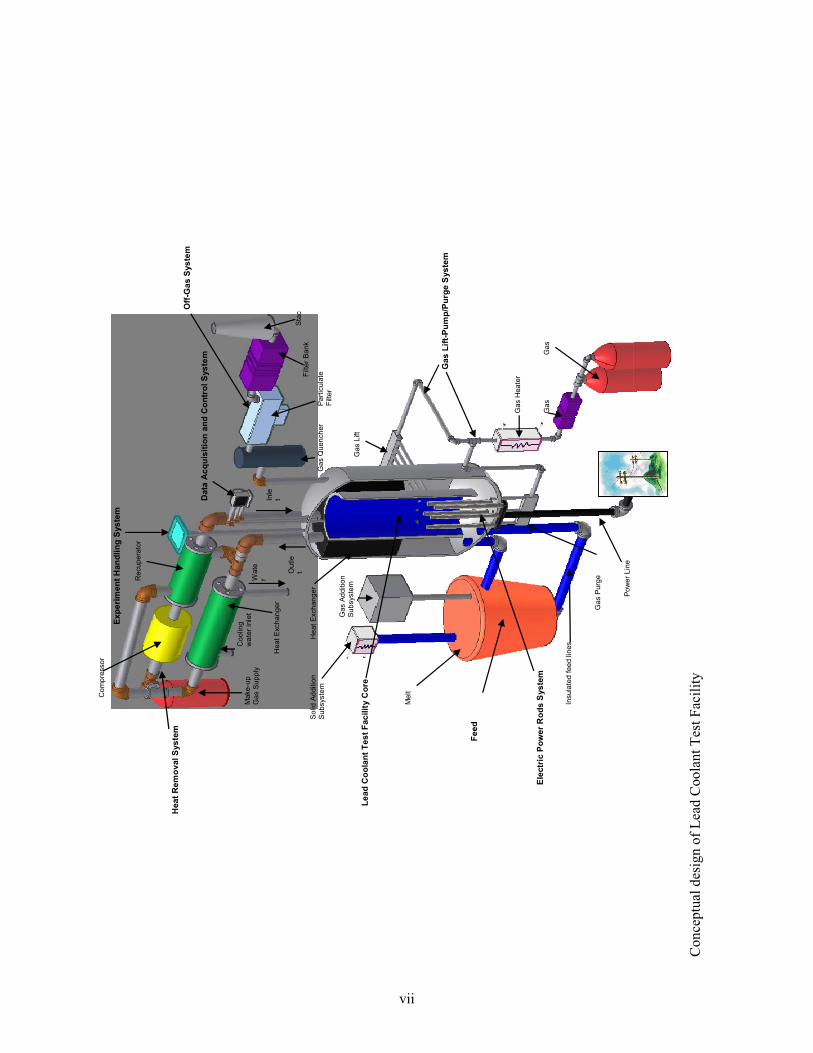


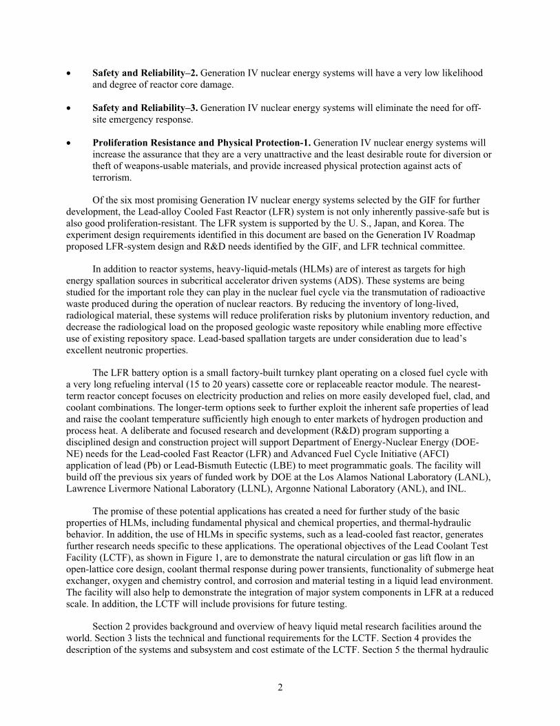
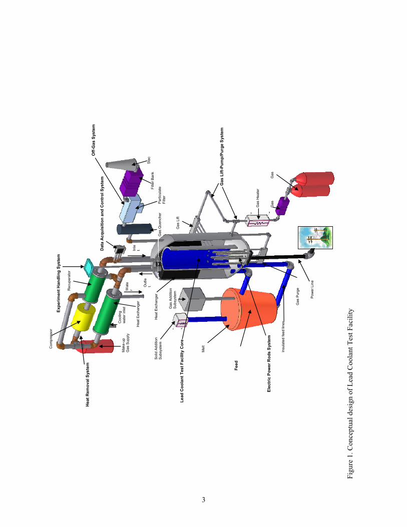
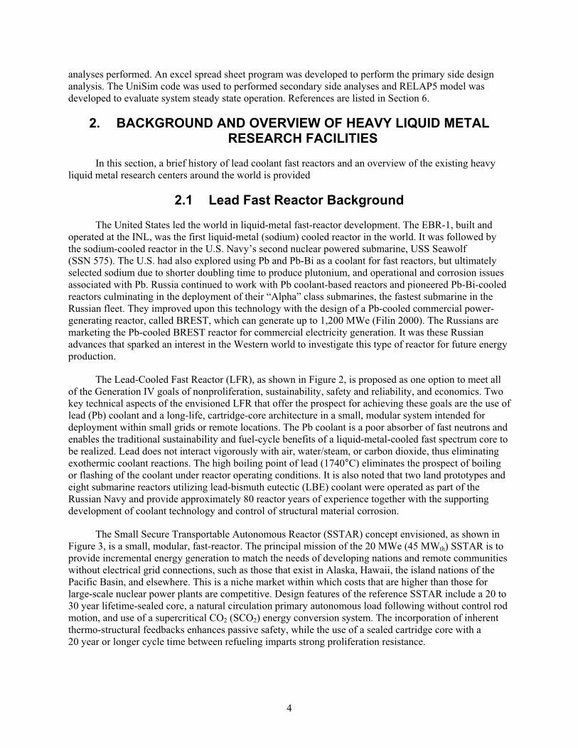

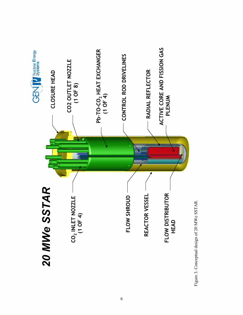
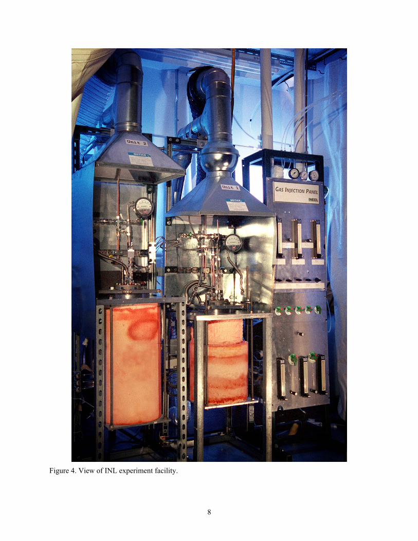
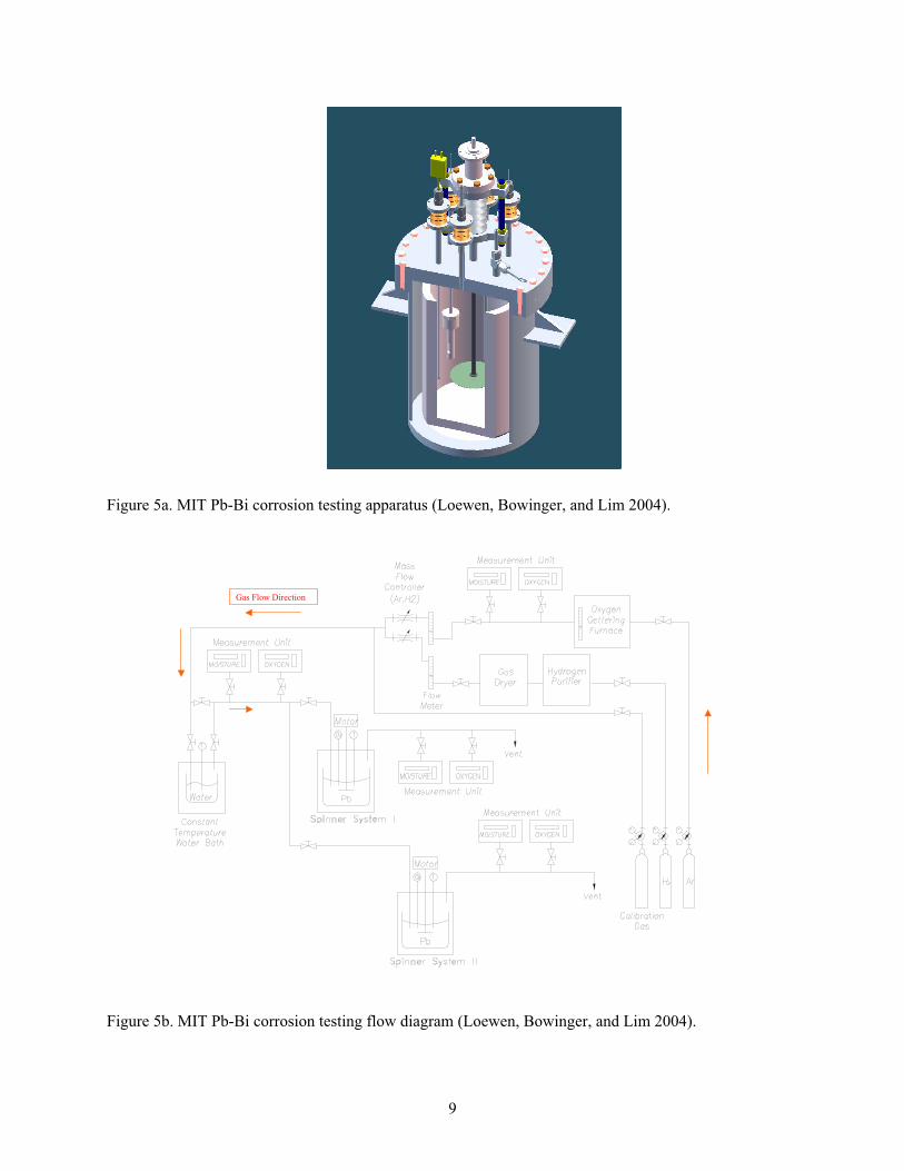
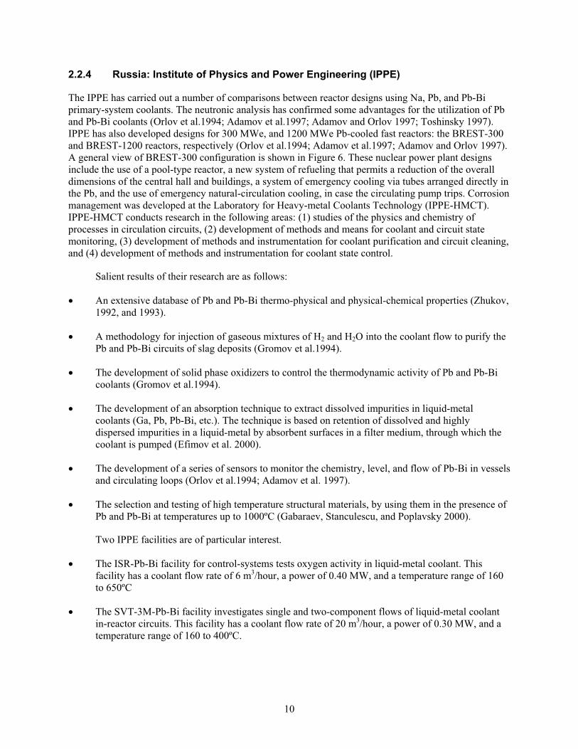
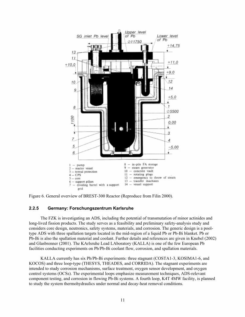
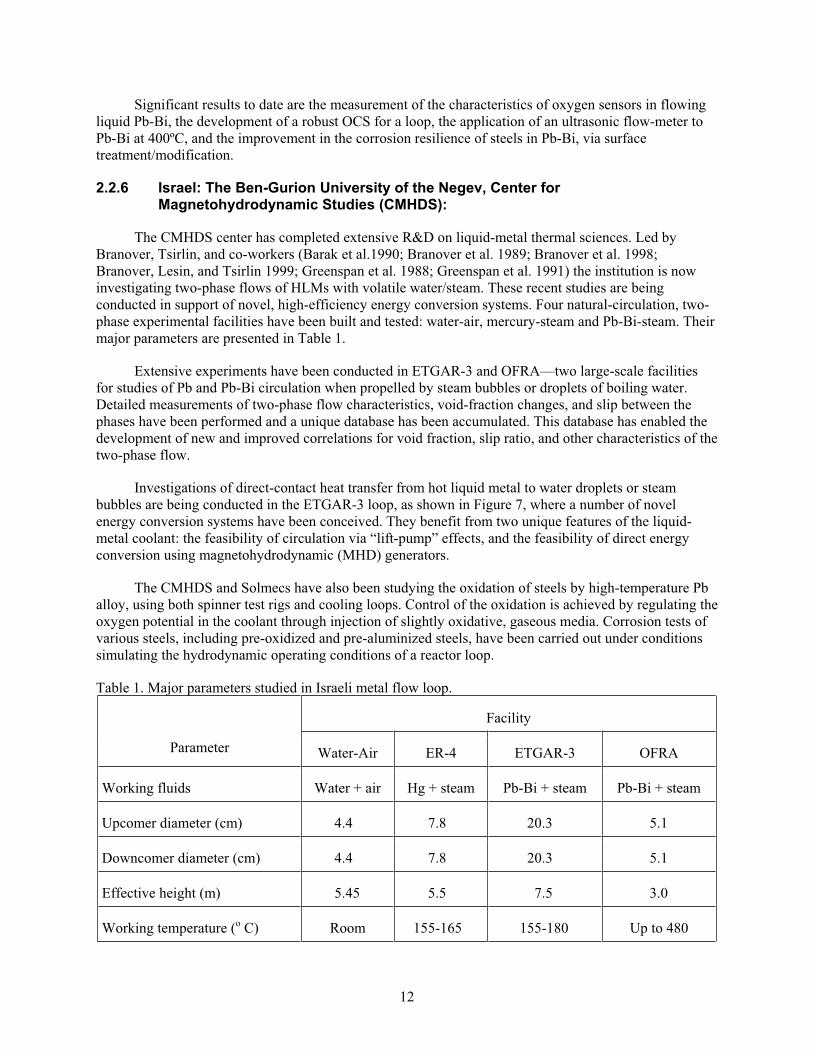
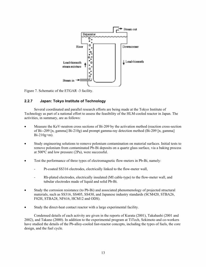
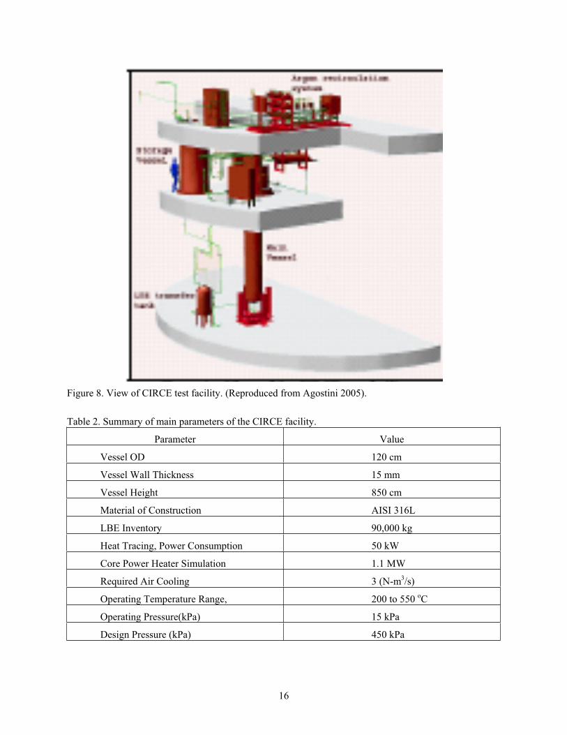


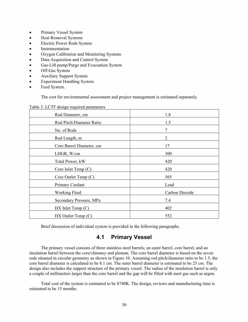

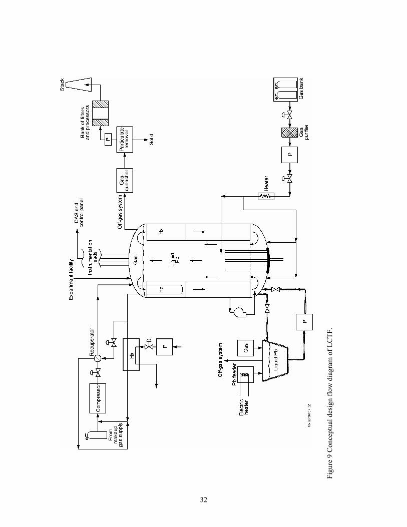


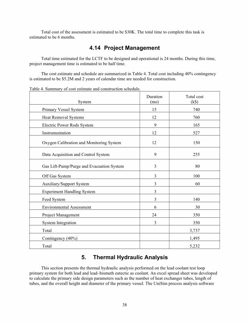
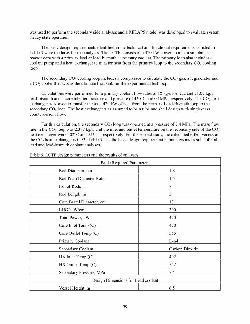
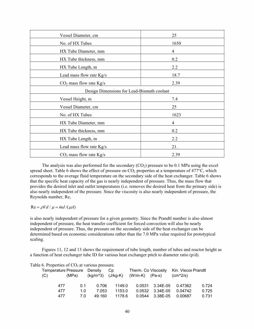
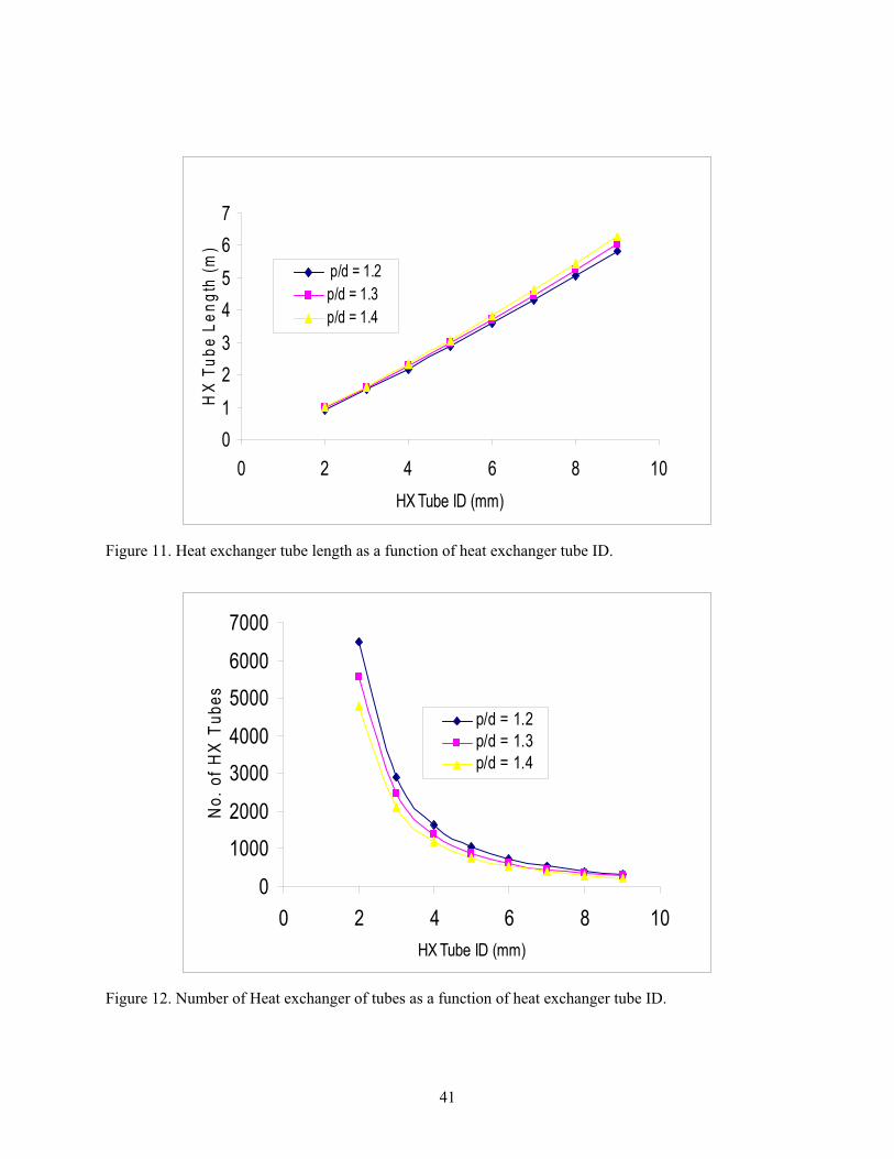
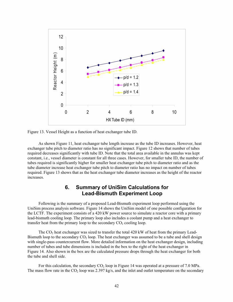
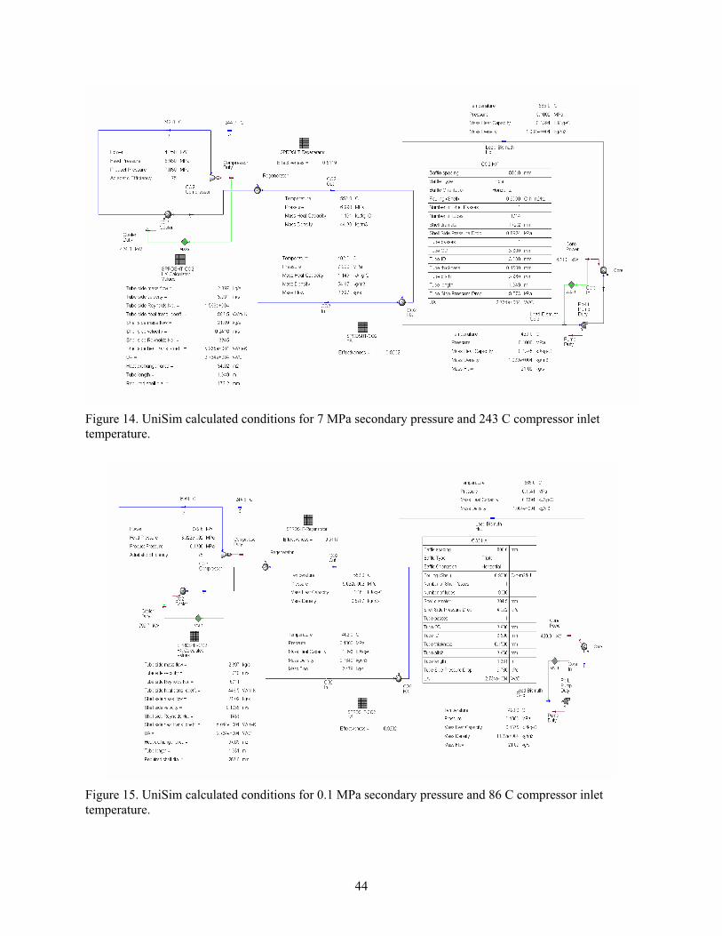
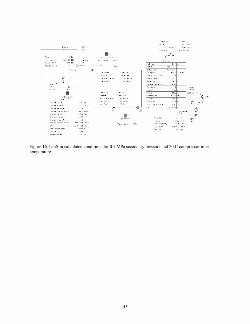
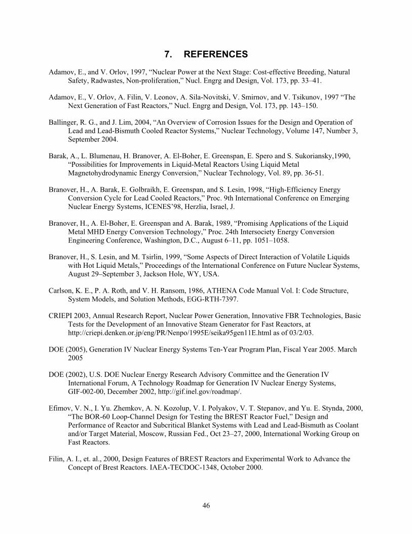


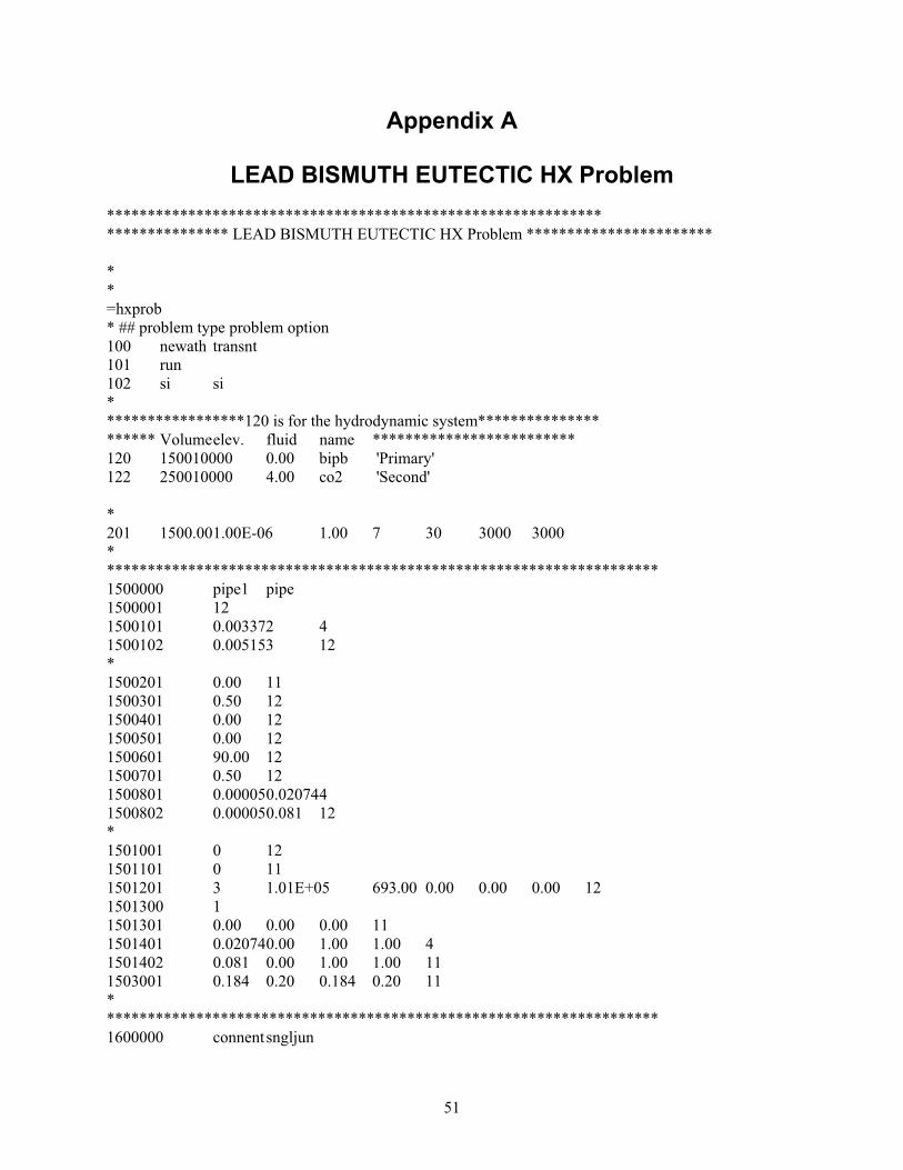
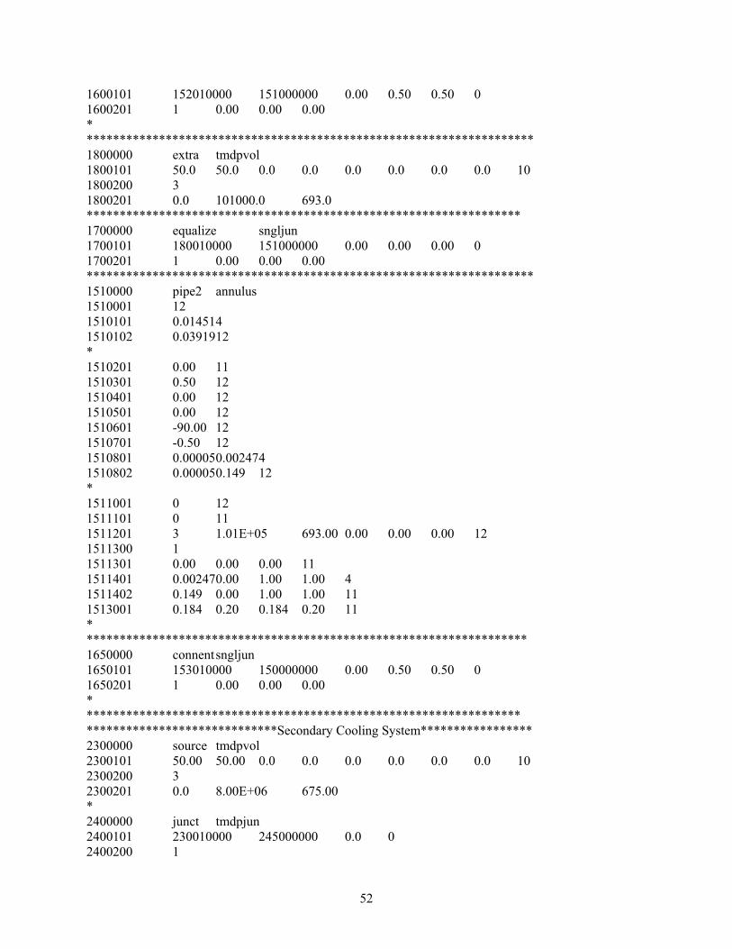

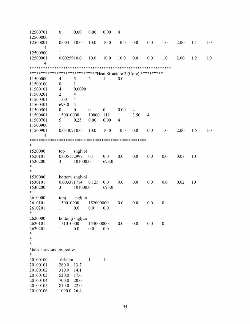


![Affordable ultra-high rotation speed up to 75,000 RPM! · CM-CV-R016-040-4-A (TBV1304) Rotation speed & Coolant flow/Coolant pressure Coolant pressure [bar] Rotation speed Coolant](https://static.documents.pub/doc/80x56/5f7d724b4720fb47ad029f32/affordable-ultra-high-rotation-speed-up-to-75000-rpm-cm-cv-r016-040-4-a-tbv1304.jpg)
![INDEX [reliefweb.int]reliefweb.int/sites/reliefweb.int/files/resources/maps_index.pdf · INDEX Index Health facility name Functional Status Health facility type Structure Type 0 1000](https://static.documents.pub/doc/80x56/5e89a2a5e988f11bf13a6b08/index-index-index-health-facility-name-functional-status-health-facility-type.jpg)

