Leak-Before-Break Evaluation for Surge Line APR1400-Z-M-NR-14016-NP, Rev.0 KEPCO & KHNP Non-Proprietary Leak-Before-Break Evaluation for Surge Line Revision 0 Non-Proprietary November 2014 Copyright ף2014 Korea Electric Power Corporation & Korea Hydro & Nuclear Power Co., Ltd All Rights Reserved
Transcript
Leak-Before-Break Evaluation for Surge Line APR1400-Z-M-NR-14016-NP, Rev.0
KEPCO & KHNP
Non-Proprietary
Leak-Before-Break Evaluation for Surge Line
Revision 0
Non-Proprietary
November 2014
Copyright 2014
Korea Electric Power Corporation &
Korea Hydro & Nuclear Power Co., Ltd
All Rights Reserved
Leak-Before-Break Evaluation for Surge Line APR1400-Z-M-NR-14016-NP, Rev.0
KEPCO & KHNP ii
Non-Proprietary
REVISION HISTORY
Revision Date Page Description
0 November
2014 All First Issue
This document was prepared for the design certification
application to the U.S. Nuclear Regulatory Commission and
contains technological information that constitutes intellectual
property.
Copying, using, or distributing the information in this
document in whole or in part is permitted only by the U.S.
Nuclear Regulatory Commission and its contractors for the
purpose of reviewing design certification application
materials. Other uses are strictly prohibited without the
written permission of Korea Electric Power Corporation and
Korea Hydro & Nuclear Power Co., Ltd.
Leak-Before-Break Evaluation for Surge Line APR1400-Z-M-NR-14016-NP, Rev.0
KEPCO & KHNP iii
Non-Proprietary
ABSTRACT
This report presents the methodology and results of the leak-before-break (LBB) evaluation of the Advanced Power Reactor 1400 U.S. Nuclear Regulatory Commission Design Certification surge line. The purpose of the LBB evaluation is to demonstrate that the highest stressed location in the surge line would leak before fracturing. The locations of highest stress for every type of material used in the surge line were evaluated, and the results demonstrate that the LBB acceptance criteria with a 1.89 L/min (0.5 gpm) leak detection capability are met. Thus reasonable assurance of the integrity of the surge line is provided relative to pipe rupture.
Leak-Before-Break Evaluation for Surge Line APR1400-Z-M-NR-14016-NP, Rev.0
Leak-Before-Break Evaluation for Surge Line APR1400-Z-M-NR-14016-NP, Rev.0
KEPCO & KHNP vii
Non-Proprietary
ACRONYMS AND ABBREVIATIONS
APR1400 Advanced Power Reactor 1400
ASME American Society of Mechanical Engineers
ASTM ASTM International
DC Design Certification
EPRI Electric Power Research Institute
FEM finite element model
GTAW gas tungsten arc welds
HL hot leg
J-R Curve measure of resistance to tearing
LBB leak-before-break
LDS leak detection system
LOCA loss of coolant accident
NO normal operating(operation)
NRC U.S. Nuclear Regulatory Commission
PED piping evaluation diagram
PICEP pipe crack evaluation program
PWR pressurized water reactor
PZR pressurizer
RCP reactor coolant pump
RCS reactor coolant system
RV reactor vessel
SAM seismic anchor motion
SF stratified flow
SG steam generator
SL surge line
SMAW submerged metal arc weld
SRP Standard Review Plan
SSE safe shutdown earthquake
TS Trade Secret
Leak-Before-Break Evaluation for Surge Line APR1400-Z-M-NR-14016-NP, Rev.0
KEPCO & KHNP viii
Non-Proprietary
Leak-Before-Break Evaluation for Surge Line APR1400-Z-M-NR-14016-NP, Rev.0
KEPCO & KHNP 1
Non-Proprietary
1 INTRODUCTION
1.1 Purpose
This report presents the methodology and results of the leak-before-break (LBB) evaluation of the Advanced Power Reactor (APR1400) U.S. Nuclear Regulatory Commission (NRC) Design Certification (DC) surge line.
1.2 Scope
The scope of this report is limited to the integrity of the APR1400 surge line relative to pipe rupture.
1.3 Background
Structures, systems, and components important to safety were previously required to be appropriately protected against the dynamic effects of missiles, pipe whip, and discharging fluids that could result from a design basis loss of coolant accident. Although the assumption of an instantaneous double ended pipe break in large high energy lines provided a convenient way to envelop the loads that could result from pipe rupture, the assumption had little or no relationship to actual behavior of such pipes. The assumption also led to a requirement for substantial protective measures to guard against the consequence of such postulated breaks to systems that were expensive to build and maintain, and to a potential degradation of plant safety. The placement of pipe whip restraints degrades plant safety if thermal expansion is restricted and the accessibility for and effectiveness of in-service inspection is reduced.
Research on elastic-plastic fracture mechanics in the last decade has produced a way to justify a more reasonable alternative: leak-before-break. The premise of LBB is that the materials used in nuclear power plant piping are sufficiently tough that even a large through-wall crack, which could result in coolant leak rates in excess of those detectable by present leak detection systems, would remain stable and would not result in a double-ended guillotine break under maximum loading conditions.
1.4 Summary of Leak-Before-Break Analysis Process
Guidance for the LBB analysis is provided in NUREG-0800, Standard Review Plan (SRP), Section 3.6.3(SRP 3.6.3; Reference 1) and NUREG 1061, Vol. 3 (Reference 2).
The LBB process is an analytical evaluation to demonstrate that the highest stressed location in a pipe under the worst loading condition would leak before fracturing with a pre-existing crack leaking at a rate 10 times the leak detection capability.
LBB analyses are performed for the highest stress location of each type of material in the surge line. All break locations, which could result in pipe whip and jet impingement that would target essential safe shutdown equipment, are bounded by the highest stress location. The major parameters that are used in the analyses are loads and load combinations, leak detection capability, material properties, and a crack growth law.
An LBB piping evaluation diagram (PED) is used during the layout and design of the surge line to provide design criteria that satisfy LBB. LBB PEDs are developed according to the procedure shown in Figure 1-1 and the methodology as described in Subsection 6.2.
Leak-Before-Break Evaluation for Surge Line APR1400-Z-M-NR-14016-NP, Rev.0
KEPCO & KHNP 2
Non-Proprietary
Figure 1-1 LBB Design Criteria Development Diagram
Select Leak Detection System
Capability
10 x Leak Detection System Capability
10 x Leak Detection System Capability
Select Pipe Size and Material
Select Low Normal Operating Loads
Select High Normal Operating Loads
Detectable Leakage Crack Lengths
2 x Detectable Leakage Crack
Lengths
Load J-a Curves Load J-a Curves
J-dJ/da Curves J-dJ/da CurvesMaterial J-a Curves
Max Load
LBB Piping Evaluation Diagram
Normal Operating Load vs. Max Design Load
Leak-Before-Break Evaluation for Surge Line APR1400-Z-M-NR-14016-NP, Rev.0
KEPCO & KHNP 3
Non-Proprietary
2 DESIGN PARAMETERS OF THE SURGE LINE
The approach taken in the APR1400 design includes the specific LBB considerations in the piping design. One aspect of the LBB evaluation approach is the performance of a preliminary LBB evaluation prior to and independent of pipe routing. The evaluation is used to establish LBB acceptance criteria in terms of a range of normal operating (NO) and maximum design loads. An LBB piping evaluation diagram (LBB PED) is developed and is used to route, design and support the piping system within a range of design parameters.
2.1 Description of Surge Line
The APR1400 surge line is a 300 mm (12 inch) schedule 160 pipe made of SA-312 Type 347 stainless steel. The pipe subsections are welded together in the shop or field using gas tungsten arc welds (GTAW). The safe-ends of the surge line are SA-182 F347 stainless steel, and are welded to the hot leg and pressurizer nozzles in the shop by means of the Inconel GTAW process. The surge line routing and intermediate support selection are APR1400 plant specific and are designed to accommodate a stratified flow condition which may occur during plant operations. Figure 2-1 is a schematic of the surge line routing. Figure 2-2 shows the geometry of HL nozzle and PZR nozzle
2.2 Design Parameters
Piping design parameters, including pipe size, properties of base metal, weld metal, and minimum detectable leakage crack length, form the basis for developing the LBB acceptance criteria curves (i.e, the LBB PEDs). To demonstrate that LBB acceptance criteria are met, the piping system is designed so that the load at the highest stressed point for each material falls within the acceptance criteria area on the LBB PED.
Table 2-1 shows the piping design parameters used for developing the LBB PEDs and constitutes the piping design requirements for LBB.
Leak-Before-Break Evaluation for Surge Line APR1400-Z-M-NR-14016-NP, Rev.0
KEPCO & KHNP 4
Non-Proprietary
Table 2-1 Design Parameters
TS
Leak-Before-Break Evaluation for Surge Line APR1400-Z-M-NR-14016-NP, Rev.0
KEPCO & KHNP 5
Non-Proprietary
1,2,3 ..... : Node identification used in surge line piping analysis F Field weld
S Shop weld
Figure 2-1 Surge Line Pipe Routing Schematic
PZR
(F)10
9
8
7473
72 71
62
61
5
2
1
(S)9B
9A(S)
8B(F) 8A
(S)
(S)72B
(S)72A (F)
71B 71A(S)
62B(S)
62A(F)
61B(S)61A(S)
5B(S)5A(F)
2B(S)
2A(S)
(F)
Y
X(Plant North)
Z
Leak-Before-Break Evaluation for Surge Line APR1400-Z-M-NR-14016-NP, Rev.0
KEPCO & KHNP 6
Non-Proprietary
(a) Hot Leg Nozzle
(b) Pressurizer Nozzle
Figure 2-2 Geometry of Nozzles for Surge Line
TS
TS
Leak-Before-Break Evaluation for Surge Line APR1400-Z-M-NR-14016-NP, Rev.0
KEPCO & KHNP 7
Non-Proprietary
3 LOADS AND LIMITING LOCATIONS FOR LBB
3.1 Loads
The surge line is analyzed using the ADLPIPE (Reference 3) piping computer code to determine forces and moments in the pipe. The resulting loads due to NO, stratified flow conditions and seismic loadings (safe shutdown earthquake [SSE]) are computed and evaluated to provide appropriate loads for the LBB evaluation.
The following three cases are selected to determine the stratified flow loads:
1. Top to bottom differential temperature of 3.3 °C (38 °F) at full power operation condition.
2. Top to bottom differential temperature of 171.1 °C (340 °F) at high temperature condition (345 °C (653 °F) – 156.1 °C (313 °F)).
3. Top to bottom differential temperature of 171.1 °C (340 °F) at low temperature condition (237.8 °C (460 °F) – 48.9 °C (120 °F)).
Cases no. 2 and 3 are used in the stability analysis. Case no. 1 is the stratified flow condition that takes place during normal plant operation and is part of the NO thermal loading. The terms of full-power NO load (deadweight, 100 percent power linear thermal expansion, pressure) and 3.3 °C (38 °F) stratified flow load are combined algebraically to determine the leakage crack length. The load combination method of determining the NO load is described in Subsection 6.2.2.
For the crack stability evaluation, the following two cases are considered when obtaining the bending moment in each principal coordinate:
1. The full-power NO load and seismic (SSE) load are added absolutely
2. Deadweight, heat-up linear thermal expansion, pressure and 171.1 °C (340 °F) stratified flow (SF) load components are summed algebraically.
The maximum design load at any time during the plant operation is the loading used in the stability analysis. The surge line is evaluated for the larger of either NO+SSE (Case no.1) or stratified flow (Case no.2) above. Subsection 6.2.2 describes the load combination method of determining the maximum design load.
The resultant bending moments are obtained from the square root of the sum of the squares as follows: ( ) = ( ) + ( ) + ( )Where:
Mi denotes the ith component of moment (i=1,2,3)
M denotes the total moment.
This moment provides the basis for the calculation of the pipe stress used to find the maximum stressed locations in the surge line.
Only the transverse bending moments are used to determine the moment for the stability analysis as follows:
Leak-Before-Break Evaluation for Surge Line APR1400-Z-M-NR-14016-NP, Rev.0
KEPCO & KHNP 8
Non-Proprietary
( ) = ( ) + ( ) The loads are calculated for several locations along the surge line. Figure 2-1 illustrates the basic surge line routing and locations of different base materials and welds. Figure 3-1 shows the resultant bending moments along the surge line. Figure 3-2 shows the transverse bending moments along the surge line.
3.2 Limiting Points for Leak-Before-Break Evaluation
LBB is required by SRP 3.6.3 to be applied to an entire piping system or analyzable portion, which typically consisted of segments between anchor points. Locations of the highest maximum design stress are determined for each type of material in the surge line in order to define the locations where the LBB evaluation is performed. Locations of the highest maximum design stress are based on the calculation of the combined stresses from the maximum design load described in Subsection 3.1.
Figure 3-3 shows the resulting stress from SF and NO+SSE loads shown in Figure 3-1. The stress is derived from all three components of the piping moments using ASME Code stress intensity factors (ASME Code Section III, Table NB-3681(a)-1). From Figure 3-3, the highest stress is at the weld between the pressurizer nozzle and surge line (Node 10 in Figure 2-1), the second highest stress is at the weld between the hot leg nozzle and surge line (Node 1 in Figure 2-1), and the third highest stress is at the weld between the second elbow from the pressurizer nozzle and intermediate pipe (Node 8B in Figure 2-1).
The following three locations are selected as limiting points for the LBB evaluation.
1. The interface between the pressurizer nozzle and surge line (Node 10 in Figure 2-1)
2. The interface between hot leg nozzle and surge line (Node 1 in Figure 2-1)
3. Intermediate pipe(Node 8B in Figure 2-1)
LBB PEDs are developed and LBB is evaluated using LBB PEDs at the above three locations. A summary of NO and maximum design loads for evaluating the crack stability at each limiting location is given in Table 3-1.
Leak-Before-Break Evaluation for Surge Line APR1400-Z-M-NR-14016-NP, Rev.0
KEPCO & KHNP 9
Non-Proprietary
Table 3-1 Loads for Crack Stability Evaluation
TS
Leak-Before-Break Evaluation for Surge Line APR1400-Z-M-NR-14016-NP, Rev.0
KEPCO & KHNP 10
Non-Proprietary
Figure 3-1 Resultant Moments for SF and NO+SSE Loads
TS
Leak-Before-Break Evaluation for Surge Line APR1400-Z-M-NR-14016-NP, Rev.0
KEPCO & KHNP 11
Non-Proprietary
Figure 3-2 Transverse Bending Moments for SF, NO+SSE and NO Loads
TS
Leak-Before-Break Evaluation for Surge Line APR1400-Z-M-NR-14016-NP, Rev.0
KEPCO & KHNP 12
Non-Proprietary
Figure 3-3 Stresses due to SF and NO+SSE Loads
TS
Leak-Before-Break Evaluation for Surge Line APR1400-Z-M-NR-14016-NP, Rev.0
KEPCO & KHNP 13
Non-Proprietary
4 MATERIAL PROPERTIES
4.1 Materials of piping portions subject to LBB application
In order to perform the LBB analysis, the tensile and fracture toughness properties of the surge line piping material must be known. For a conservative approach, the LBB analysis uses the low bound material properties of each material.
The surge line of interest to the LBB analysis contains the followings eight (8) materials;
1. Surge line piping, SA-312 TP 347 stainless steel
2. Surge line elbows, SA-403 WP 347 stainless steel
3. Surge line safe-ends, SA-182 F 347 stainless steel
4. Hot leg nozzle, SA-508 Grad 1a
5. Pressurizer nozzle, SA-508 Grade 3 Class 1
6. Surge line shop welds, GTAW SFA-5.9 ER347 filler metal
7. Surge line field welds, GTAW SFA-5.9 ER347 filler metal
8. Safe-end shop welds, GTAW SFA-5.14 ERNiCrFe-7 filler metal
4.2 Ramberg-Osgood Curve
The detectable leakage crack length is determined based on the leak detection capability using the industry standard pipe crack evaluation program (PICEP)(Reference 4) developed by the Electric Power Research Institute (EPRI). The crack leakage analyses performed by PICEP require tensile material properties.
The best fit material properties, corresponding to the pipe base metal, expressed in the form of the Ramberg-Osgood parameters, are used. The Ramberg-Osgood law is a representation of the material's true stress-strain curve. The three Ramberg-Osgood parameters , E o are needed to define the law.
Where: = Ramberg-Osgood material constant n = material hardening coefficient = strain = stress o = yield strain ( o = o /E)
o = 0.2 percent offset yield stress
E = elastic modulus
Because the lower-bound stress-strain tensile properties would result in a larger crack opening
Leak-Before-Break Evaluation for Surge Line APR1400-Z-M-NR-14016-NP, Rev.0
KEPCO & KHNP 14
Non-Proprietary
displacement and consequently shorter crack length than those of best fit stress-strain tensile properties at the same leak rate, it is more conservative to use the best fit base metal tensile properties instead of the lower bound base metal in PICEP.
The Ramberg-Osgood parameters derived from the LBB test data for the reference plant and used in the PED development are shown in Table 4-1. The Ramberg-Osgood material characterization described in Table 4-1 is for the detectable crack length calculation and the Ramberg-Osgood fit to these data is described in Figure 4-1.
4.3 Stress-Strain Curves
The tensile properties of the materials are represented by their stress-strain curves and demonstrate that the material behave in a ductile manner near the actual plant operating temperature.
The stress-strain curves were taken from the LBB test data for the reference plant. The tensile properties shown in Table 4-1 and Figure 4-2 were used in the crack stability evaluation. Figure 4-2 shows the lower bound stress-strain curves for each material of surge line. All the curves of Figure 4-2 were used in the PED development.
4.4 Toughness Properties
One of the other major material parameters needed for the LBB evaluation is the J-R curve, which is a measure of the resistance to tearing. This property is used to characterize the propensity for crack extension and stability in the piping materials under consideration.
Fracture toughness tests are performed in accordance with ASTM E-1820 (Reference 5) to determine the J-R curves which are determined at a temperature near the upper range of normal plant operation.
The J-R curve data are obtained from standard 1T compact tension specimens which are side-grooved 10 percent on each side. Several J-R tests are performed on each material to provide an adequate basis for assessing the behavior of the materials.
The J-R curves are obtained using specimens with 1” thickness and for as large crack extensions as possible for the given specimen size. Because the specimens are small, the crack lengths are small compared to the length of crack required to be assumed in the LBB analysis. Thus, extrapolation techniques are used.
The J-R toughness data for each surge line material were obtained from the tests of the surge line materials of the reference plant. The material J-resistance (J-R) curves were taken from actual archival materials for intermediate pipe, safe end, elbow, and weld metals that were fabricated from the SA-312, SA-182, and SA-403, Type 347 stainless steel and GTAW, respectively. Review of the test data for surge line materials were shown that the lowest data were for the field weld metal of GTAW of surge line piping. Thus, this lowest field weld material data was used to generate the lower bound J-R curve for the stability evaluation of the surge line. In order to extrapolate the limited data, the method described in ASTM E-1820 was used to generate the power law curve fits for the data. No Jmax or exclusion lines are used to limit the valid data for fitting the power law. The equations derived in this manner were then used as the means to extrapolate the data to large crack extensions. This is a conservative approach because there is a substantial amount of data that demonstrate that non-side-grooved 1T compact tension specimens and/or larger planform test specimens produce significantly higher J-R curve behavior for the same material.
The material J-R curves were taken from the reference plant LBB test data. J-R parameters used in the PED development are given in Table 4-2 and plotted in Figure 4-3.
Leak-Before-Break Evaluation for Surge Line APR1400-Z-M-NR-14016-NP, Rev.0
KEPCO & KHNP 15
Non-Proprietary
Table 4-1 Material Constants TS
Leak-Before-Break Evaluation for Surge Line APR1400-Z-M-NR-14016-NP, Rev.0
KEPCO & KHNP 16
Non-Proprietary
Table 4-2 Parameters on J-R Curves
(1) 2C1mat a)(CJ
Where,
unit of C2 is dimensionless.
TS
Leak-Before-Break Evaluation for Surge Line APR1400-Z-M-NR-14016-NP, Rev.0
KEPCO & KHNP 17
Non-Proprietary
Figure 4-1 Stress-Strain Curve for Leakage Crack Length Calculation
TS
Leak-Before-Break Evaluation for Surge Line APR1400-Z-M-NR-14016-NP, Rev.0
KEPCO & KHNP 18
Non-Proprietary
Figure 4-2 Stress-Strain Curves for Crack Stability Analysis
TS
Leak-Before-Break Evaluation for Surge Line APR1400-Z-M-NR-14016-NP, Rev.0
KEPCO & KHNP 19
Non-Proprietary
Figure 4-3 J-R Curve for Crack Stability Analysis
TS
Leak-Before-Break Evaluation for Surge Line APR1400-Z-M-NR-14016-NP, Rev.0
KEPCO & KHNP 20
Non-Proprietary
5 DETERMINATION OF CRACK LENGTH
Hypothesized through-wall cracks must open sufficiently to allow leak detection by normal leakage monitoring under normal full-power loadings. The leak detection capability of the APR1400 is 1.89 L/min (0.5 gpm). The guidance in SRP 3.6.3 is that the size of the flaw should be large enough so that leakage from the flaw during normal operation would be 10 times greater than the minimum leakage the detection system is capable of sensing, unless otherwise justified. The LBB evaluation of the surge line is therefore based on a leakage rate of 18.9 L/min (5 gpm).
The leakage crack length for a required 18.9 L/min (5 gpm) flow depends on pipe loading, thermodynamic conditions, and assumed crack surface roughness conditions. The elastic-plastic estimation method described in EPRI NP-1931 (Reference 6) is used to find the crack opening displacement for a given loading. PICEP is used to calculate the flow for a given crack length and loading. The crack morphology parameters used in PICEP are shown in Table 5-1.
The determination of the leakage crack length for the intermediate point is straight forward. The NO load for this point from Table 3-1 in PICEP is used to obtain a list of crack lengths versus flow rate at the end of PICEP run.
At the interface between the HL and PZR nozzles and surge line, consideration of the nozzle requires an iterative procedure to find an appropriate crack length that leaks at 18.9 L/min (5 gpm) and uses both the finite element model (FEM) used for the crack stability analysis and PICEP. Because the stiffness of the nozzle is included in the stability analysis, it is also included in the leakage calculation. The iterative procedure for calculating crack length at the nozzle/pipe interface is as follows:
1. Assume a crack length in the FEM
2. Apply NO loads to the FEM and calculate the crack opening area
3. Using PICEP with the same crack length, vary the applied moment until the crack opening area becomes the same area as calculated with the FEM.
4. If the flow calculated by PICEP is greater than 18.9 L/min (5 gpm), the crack length is decreased, and the procedure starts over at Step 1. If the calculated flow is less than 18.9 L/min (5 gpm), the crack length is increased, and the procedure starts over at Step 1. If the flow is 18.9 L/min (5 gpm), the procedure is completed.
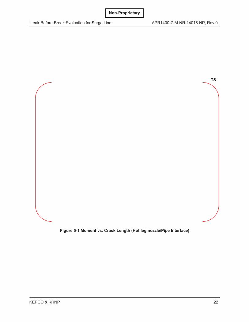
For the purpose of generating analysis data for LBB PEDs, the moment versus crack length for an 18.9 L/min (5 gpm) flow is plotted. Each curve provides the relationship between NO load and the crack length that gives an 18.9 L/min (5 gpm) flow. The moment versus crack length curves are shown in Figures 5-1 through 5-3. These curves are the crack lengths associated with 18.9 L/min (5 gpm) flow for a given moment. An analysis using a longer crack at a given moment results in a flow greater than 18.9 L/min (5 gpm).
Leak-Before-Break Evaluation for Surge Line APR1400-Z-M-NR-14016-NP, Rev.0
KEPCO & KHNP 21
Non-Proprietary
Table 5-1 Crack Morphology Parameters TS
Leak-Before-Break Evaluation for Surge Line APR1400-Z-M-NR-14016-NP, Rev.0
KEPCO & KHNP 22
Non-Proprietary
Figure 5-1 Moment vs. Crack Length (Hot leg nozzle/Pipe Interface)
TS
Leak-Before-Break Evaluation for Surge Line APR1400-Z-M-NR-14016-NP, Rev.0
KEPCO & KHNP 23
Non-Proprietary
Figure 5-2 Moment vs. Crack Length (Intermediate Pipe)
TS
Leak-Before-Break Evaluation for Surge Line APR1400-Z-M-NR-14016-NP, Rev.0
KEPCO & KHNP 24
Non-Proprietary
Figure 5-3 Moment vs. Crack Length (Pressurizer nozzle/Pipe Interface)
TS
Leak-Before-Break Evaluation for Surge Line APR1400-Z-M-NR-14016-NP, Rev.0
KEPCO & KHNP 25
Non-Proprietary
6 CRACK STABILITY EVALUATIONS
6.1 Finite Element Model Description
6.1.1 Geometry and Boundary Conditions
The FEM for a typical crack stability evaluation is shown in Figure 6-1. A close-up of the crack tip area is shown in Figure 6-2. The FEM is simply a means of applying the pressure and moment loading to a section of pipe containing the hypothetical crack at some location in the pipeline. Two planes of symmetry are used to minimize the size of FEMs for intermediate pipe of the surge line. Therefore, each model represents one quarter of the pipe, as shown in Figure 6-1(a). One plane of symmetry for the crack near the hot leg nozzle and pressurizer nozzle, as shown in Figure 6-1(b) is used to minimize the model size, meaning that half of the nozzle and pipe is modeled.
The selected pipe length is equal to at least five times pipe diameters so the point of load application is not close to the crack tip region. The mesh uses 20 node iso-parametric brick reduced integration elements. Boundary conditions are imposed on the model based on symmetry and crack location. The crack surface area is free from constraint.
6.1.2 Loadings
The internal pressure appropriate to the NO conditions of each piping system is applied to the inner surface of the pipe, and half of the internal pressure is applied to the crack face to account for the pressure drop across the crack. An axial end load traction, which when integrated over the pipe cross-sectional area, is equal to the continuity axial force, is applied to the far end of the pipe. Moments are applied as a linearly varying traction to the far end of the pipe.
6.1.3 Stability Evaluation
The stability of through-wall cracks is evaluated using the J-integral parameter, which is related to the energy release rate at the crack tip. The J-integral value is determined by finite element analysis for maximum design load included in the crack stability evaluation using the ABAQUS program (Reference 7).
The stability of the cracked pipes is assessed by comparing the J-integral value because of the applied loads on the pipe to the crack resistance of the material. The stability criterion for ductile crack extension that is used is as follows: <
and < Then, reasonable assurance of crack stability is provided.
The change in the J-integral with crack length “a” is determined by analyzing several crack lengths in the region of interest. For a leakage crack of length “a”, crack lengths, “a”, “a-d”, and “a+d” are analyzed as shown in Figure 6-3. Similarly, the change in the J-integral with the crack length in the region of length ”2a” is determined by analyzing cracks with lengths ”2a”, “2a-d”, and “2a+d”. This method provides the derivative information in the two regions of interest. The variation of J with crack length in the region of “a” and ”2a” is plotted along with the material curve. The evaluation of the plots allows for direct verification of the stability criteria.
Leak-Before-Break Evaluation for Surge Line APR1400-Z-M-NR-14016-NP, Rev.0
KEPCO & KHNP 26
Non-Proprietary
The evaluations are performed for the locations chosen to envelop all limiting cases. Both the pipes with imes the maximum design load and the pipes with twice the
leakage crack length subject to the maximum design load are demonstrated to have the significant margin between the material curve and the loading curve, indicating that all pipe locations satisfy the LBB crack stability criteria.
For each load step in the analysis, the loading curve as a function of crack length is fit to a quadratic: ( ) = + + The values at “a” and “a±d” provide the boundary conditions necessary to evaluate the constants C1, C2, and C3. At each loading point, the function is differentiated. This provides the dJ/da values for the loading curve. The material curves J(a), dJ(a)/da are evaluated at increasing crack extension. The loading functions J(a), dJ(a)/da are evaluated at either ”a” or “2a”, whichever crack length is being evaluated. Each point on the J versus dJ/da loading curve corresponds to a different load state. As long as the loading curve stays below the material curve, <
and <
the crack growth is stable. For the case of increasing load, the loading curve eventually intersects the material curve. At this point, the crack would experience unstable crack growth. At this point of instability, =
and =
Development of the J versus dJ/da diagram for determining points of instability is shown in Figure 6-4.
6.2 LBB Piping Evaluation Diagram
6.2.1 Constructing a Leak-Before-Break Piping Evaluation Diagram
The method by which LBB PEDs are constructed allows for the evaluation of the surge line in advance of the final surge line analysis, incorporating LBB considerations into the surge line design. The three LBB PEDs for the surge line are prepared prior to the surge line design and analysis and are used to evaluate the three limiting points as provided in Subsection 3.2. The PEDs are constructed to allow the maximum design load to be plotted versus the NO load.
The maximum design load at any time during the plant operation is the loading used in the stability analysis. The surge line is evaluated for the larger of either NO+SSE load or stratified flow (SF) load. Subsection 6.2.2 describes the load combination method to determine NO and maximum design loads.
The LBB PED requires performing two complete LBB evaluations. The evaluations are for two NO loads that span the typical loadings for the surge line. A completed typical PED is shown in Figure 6-5.
Leak-Before-Break Evaluation for Surge Line APR1400-Z-M-NR-14016-NP, Rev.0
KEPCO & KHNP 27
Non-Proprietary
The procedure used for generating the PED is as follows:
1. Choose NO1 load
2. Determine leakage crack length (a1 and 2a1) with corresponding NO1 load by the approach provided in Section 5.
3. Determine the critical moment, Mcritical for a1 and 2a1 by the approach provided in Subsection 6.1.3.
4. Calculate the maximum allowable load from the critical moment, Mcritical for a1 and 2a1 = 2 (al analysis) =
and = (2al analysis) =
5. Plot Mallowable1 values at NO1 load for a1 and 2a1 analyses, respectively. This corresponds to the points labeled “1” in Figure 6-5.
6. Repeat Steps 1 through 5 for NO2 load. The results are shown in Figure 6-5, labeled “2”.
6.2.2 Method of Load Combination
The NO load and maximum design load are applied to the LBB evaluation using LBB PED.
The NO load is combined algebraically as follows: ( ) = ( ) + ( ) + ( ) + ( )
Where:
Mi = moment of ith component (i=1, 2, 3)
Thermal-100% = 100% power linear thermal expansion
Pressure-100% = pressure load at full-power operation
Stratified-100% = thermal stratified load at full-power operation
The maximum design load is combined as described below.
The larger of the following two combined loads is considered for evaluating the stability of through-cracks.
Leak-Before-Break Evaluation for Surge Line APR1400-Z-M-NR-14016-NP, Rev.0
KEPCO & KHNP 28
Non-Proprietary
SSE load includes both the SSE inertial load and the SSE SAM load.
Thermal-100% = 100% power linear thermal expansion
Stratified-100% = thermal stratified load at full-power operation
Second load: ( ) = ( ) + ( ) + ( ) + ( ) .
Where:
Mi = moment of ith component (i=1, 2, 3)
Thermal-hp = linear thermal expansion at plant heat-up
Max. stratified = maximum thermal stratification load
Only the transverse bending moments are used to determine NO and maximum design moments for LBB PED input.
6.2.3 Using a Leak-Before-Break Piping Evaluation Diagram
Once the lines marking the acceptable areas of allowable piping loads are plotted as described in Subsection 6.2.1, NO loads and corresponding maximum design loads at the limiting locations are calculated as provided in Subsections 3.1 and 3.2, and plotted on the LBB PEDs.
Figure 6-6 is an example of how the plot is used for a hypothetical line. In this example, three points fail LBB and one point passes LBB. The reasons for each failure are given in the figure.
combinedcombinedcombined MMM 23
22 )()()(
Leak-Before-Break Evaluation for Surge Line APR1400-Z-M-NR-14016-NP, Rev.0
KEPCO & KHNP 29
Non-Proprietary
(a) Intermediate Pipe of Surge Line
(b) Nozzle/Pipe Interface of Surge Line
Figure 6-1 Finite Element Model for a Typical Crack Stability Evaluation
TS
TS
Leak-Before-Break Evaluation for Surge Line APR1400-Z-M-NR-14016-NP, Rev.0
KEPCO & KHNP 30
Non-Proprietary
(a) Intermediate Pipe of Surge Line
(b) Nozzle/Pipe Interface of Surge Line
Figure 6-2 Crack Area Close-up of Finite Element Model
TS
TS
Leak-Before-Break Evaluation for Surge Line APR1400-Z-M-NR-14016-NP, Rev.0
KEPCO & KHNP 31
Non-Proprietary
Figure 6-3 Different Crack Lengths Used to Calculate Derivative
SYMMETRY
l = Leakage crack lengthal = Model crack lengthal ± d = Model crack length ± a small amount
Leak-Before-Break Evaluation for Surge Line APR1400-Z-M-NR-14016-NP, Rev.0
KEPCO & KHNP 32
Non-Proprietary
Figure 6-4 Development of a Stability Evaluation Diagram
TYPICAL LOADING
TYPICAL MATERIAL
INSTABILITY LOAD
Leak-Before-Break Evaluation for Surge Line APR1400-Z-M-NR-14016-NP, Rev.0
KEPCO & KHNP 33
Non-Proprietary
Figure 6-5 LBB Piping Evaluation Diagram
MA
XIM
UM
MO
ME
NT
NORMAL OPERATING MOMENT
2a
a
ANALYSIS #1 RESULTS
ANALYSIS #2 RESULTS
FAIL
FAIL
PASS
NO1
PASS
PASSNO2
Leak-Before-Break Evaluation for Surge Line APR1400-Z-M-NR-14016-NP, Rev.0
KEPCO & KHNP 34
Non-Proprietary
Point 1 passes LBB on “a” and “2a”
Point 2 fails maximum moment on “2a”
Point 11 fails 2 (maximum moment) on “a”
Point 14 fails 2 (maximum moment) on “a”
and maximum moment on “2a”
Figure 6-6 Use of the LBB Piping Evaluation Diagram
MA
XIM
UM
MO
ME
NT
NORMAL OPERATING MOMENT
2a
a
Leak-Before-Break Evaluation for Surge Line APR1400-Z-M-NR-14016-NP, Rev.0
KEPCO & KHNP 35
Non-Proprietary
7 RESULTS
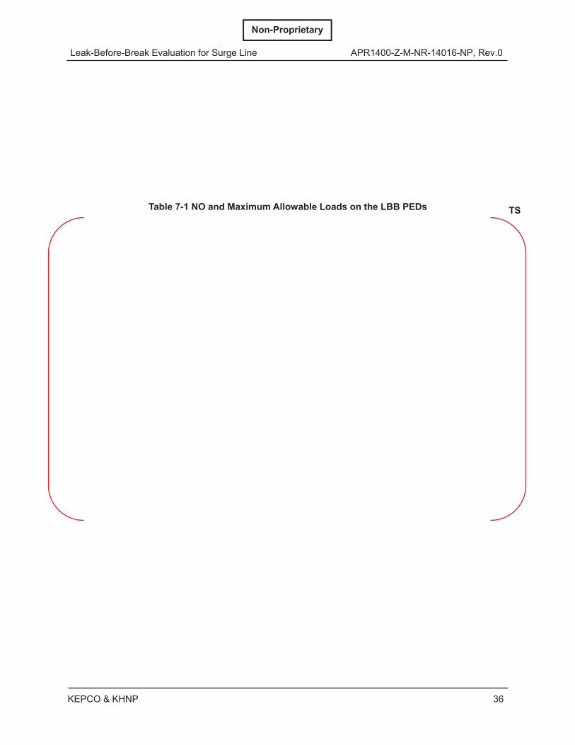
Three locations were selected as limiting points for LBB evaluations as described in Subsection 3.2. The crack stability analyses using an LBB PED were performed for the above three locations. Table 7-1 represents the maximum allowable loads and NO loads used to construct an LBB PEDs as described in Subsection 6.2.1. Table 3-1 shows NO loads and corresponding maximum design loads at the above limiting locations to be plotted on the LBB PEDs for the crack stability evaluation. The plots on the LBB PEDs are shown in the following figures:
According to the above Figures, the maximum piping loads are below the LBB PEDs demonstrating that reasonable assurance of the crack stability is provided and the fracture mechanics of the LBB requirements are satisfied.
Leak-Before-Break Evaluation for Surge Line APR1400-Z-M-NR-14016-NP, Rev.0
KEPCO & KHNP 36
Non-Proprietary
Table 7-1 NO and Maximum Allowable Loads on the LBB PEDs
TS
Leak-Before-Break Evaluation for Surge Line APR1400-Z-M-NR-14016-NP, Rev.0
KEPCO & KHNP 37
Non-Proprietary
Figure 7-1 LBB Piping Evaluation Diagram (Hot leg nozzle/Pipe Interface)
TS
Leak-Before-Break Evaluation for Surge Line APR1400-Z-M-NR-14016-NP, Rev.0
Leak-Before-Break Evaluation for Surge Line APR1400-Z-M-NR-14016-NP, Rev.0
KEPCO & KHNP 40
Non-Proprietary
8 SUMMARY AND CONCLUSIONS
All limiting locations throughout the APR1400 surge line were evaluated, and the LBB acceptance criteria with a 1.89 L/min (0.5 gpm) leak detection capability are shown to be satisfied.
Leak-Before-Break Evaluation for Surge Line APR1400-Z-M-NR-14016-NP, Rev.0
KEPCO & KHNP 41
Non-Proprietary
9 REFERENCES
1. NUREG-0800, “Standard Review Plan,” Section 3.6.3, "Leak-Before-Break Evaluation Procedures", Rev.01, U.S. Nuclear Regulatory Commission, March 2007.
2. NUREG-1061, Vol. 3, "Evaluation of Potential for Pipe Break," U.S. Nuclear Regulatory Commission, November 1984.
3. “ADLPIPE : A Computer Program for Complete Piping Analysis and Design Solution,” Rev. 10, Research Engineers, Inc., California.
4. EPRI NP-3596-SR, "PICEP : Pipe Crack Evaluation Program,” Rev. 1, Electric Power Research Institute, December 1992.
5. ASTM E 1820-09, "Standard Test Method for Measurement of Fracture Toughness," ASTM International, 2009.
6. EPRI NP-1931, “An Engineering Approach for Elastic-Plastic Fracture Analysis,” Electric Power Research Institute, July 1981.
7. “ABAQUS/Standard User’s Manual, Version 6.10-1,” Dassault Systemes Inc., 2010