LEARNING ACTIVITY # 5 5-1 # 5 Design and Build a Model Truss Bridge Learning Activity #5: Overview of the Activity In this learning activity, we will design, build, and test a model truss bridge. We will analyze the Owner’s needs, then formulate specific design requirements. We will develop a truss configuration, analyze the struc- ture, design each individual member and connection, then develop plans and specifications. Finally, we will build the bridge and test it to verify that it can carry load safely. Why? In Learning Activity #1, we played the role of the Constructor and built a model bridge that had been designed by someone else. In Learning Activity #5, we will assume the role of the Design Professional and design a new bridge with the same span length but with a different loading and a very different geometric configuration. In doing so, we will learn a process that can be used to design a bridge with practically any span length, loading, or configuration. This project provides an opportunity to apply everything we have seen in the previous four learning activi- ties. We will see how the various elements of the engineering design process fit together—how scientific principles, mathematic tools, engineering concepts, experimental data, and practical considerations contribute to the final product. We’ll see how the truss configuration is tailored to the Owner’s needs; how the structural model is derived from the truss configuration; how structural analysis results and experimental data contribute to the design of structural members; how the size and shape of connections are determined; how constructabil- ity considerations affect the final design; and how engineering computations are translated into the drawings and schedules required for construction. Finally, we will build the bridge we designed—a great way to check the validity of the design and the accuracy of the plans and specifications.
Transcript
LEARN
ING
ACTIVITY #5
5-1
#5
Design and Build a Model Truss Bridge
Learning Activity #5:
Overview of the ActivityIn this learning activity, we will design, build, and test a model truss bridge. We will analyze the Owner’s
needs, then formulate specific design requirements. We will develop a truss configuration, analyze the struc-ture, design each individual member and connection, then develop plans and specifications. Finally, we will build the bridge and test it to verify that it can carry load safely.
Why?In Learning Activity #1, we played the role of the Constructor and built a model bridge that had been
designed by someone else. In Learning Activity #5, we will assume the role of the Design Professional and design a new bridge with the same span length but with a different loading and a very different geometric configuration. In doing so, we will learn a process that can be used to design a bridge with practically any span length, loading, or configuration.
This project provides an opportunity to apply everything we have seen in the previous four learning activi-ties. We will see how the various elements of the engineering design process fit together—how scientific principles, mathematic tools, engineering concepts, experimental data, and practical considerations contribute to the final product. We’ll see how the truss configuration is tailored to the Owner’s needs; how the structural model is derived from the truss configuration; how structural analysis results and experimental data contribute to the design of structural members; how the size and shape of connections are determined; how constructabil-ity considerations affect the final design; and how engineering computations are translated into the drawings and schedules required for construction. Finally, we will build the bridge we designed—a great way to check the validity of the design and the accuracy of the plans and specifications.
5-2
Learning ObjectivesAs a result of this learning activity, you will be able to do the following:
n Explain how design-build project delivery differs from design-bid-build project delivery.
n Explain how the factor of safety is used in design.
n Explain how scientific principles, mathematic tools, engineering concepts, experimental data, and practical considerations contribute to the engineering design process.
n Design a model truss bridge to meet a set of design requirements.
n Build a model truss bridge, consistent with a set of plans and specifications.
Key TermsTo successfully complete this learning activity, you must understand the following key terms and concepts
from previous learning activities:
truss deck truss internal force right triangle
member through truss tension hypotenuse
top chord gusset plate compression Pythagorean theorem
bottom chord joint strength Owner
diagonal reaction factor of safety Design Professional
If you need to refresh your memory on any of these terms, see the Glossary in Appendix D.
Information
Using the Factor of Safety in DesignWhen we analyzed a structure in Learning Activity #3, we used the following definition for the factor of
safety:
To use this equation, we first determined the internal force in each member (by doing a structural analysis) and the strength of each member (by using our experimental data from Learning Activity #2). Then we used these numbers to calculate a unique factor of safety for every member in the structure. In short, we used known values of internal force and strength to calculate unknown factors of safety.
When we design a structure, we need to select members that are strong enough to carry load safely. Thus, in design, the unknown quantity in the equation above is the strength. The known quantities are the internal forces and the factor of safety. As before, the internal member forces are determined by a structural analysis; but in design, we will simply specify the factor of safety. We might use a design code as the basis for deciding what the factor of safety should be, or we might simply use our experience and judgment. In either case, we will choose a value that appropriately reflects the level of safety required for our structure.
LEARN
ING
ACTIVITY #5
5-3
Since strength is the unknown quantity, it makes sense to algebraically rearrange the equation above by multiplying both sides by the internal member force. The result is
To use this equation for design purposes, we will change the “equal sign” to a “greater than or equal sign,” like this:
The product on the right-hand side of this expression—the factor of safety times the internal member force—is called the required strength. This expression tells us that the actual strength of a member must be greater than or equal to its required strength. We use > because it’s always OK for a member to be “too strong.” Indeed, as we saw in Learning Activity #3, sometimes it makes good economic sense for some members in a structure to be stronger than they really need to be.
We will use the expression above as the basis for determining the size of each structural member in our design.
Design-Build Project DeliveryAs we discussed in Learning Activity #4, most public works projects in the United Sates use design-bid-build
project delivery. In this system, (1) the Design Professional develops a complete design and provides it to the Owner, (2) the Owner advertises the project, (3) construction contractors submit bids, and (4) the Owner awards the construction contract to the lowest responsive, responsible bidder. Owners typically use design-bid-build project delivery because the competitive bidding process tends to keep the construction cost low. However, this system has some significant disadvantages as well:
n In design-bid-build project delivery, the Design Professional often has only minimal involvement in the construction phase of the project. Thus the designer is not able to ensure that that structure is built as intended.
n The Constructor is never involved in the design process. Thus constructability issues may not be fully considered in the design.
n The period of time required for advertising, collecting contractors’ bids, and awarding the construction contract can be quite substantial. At this point in the process, the design is complete, and construction activity has not yet begun. Thus this entire period is essentially non-productive.
For these reasons (and others), an alternative system called design-build project delivery is becoming increasingly popular. In a design-build project, a single firm contracts with the Owner to do an entire pro-ject—both design and construction. Thus, in a design-build project, there is no break in continuity between design and construction. Coordination between the Design Professional and the Constructor is likely to be more effective, because one firm has overall responsibility for the project. Eliminating the bidding phase may also speed up the project. Indeed, with design-build project delivery it is possible for construction to begin even before the design is complete—a procedure called “fast-tracking.”
Of course, design-build project delivery also has its disadvantages. Thus the best means of project delivery always depends on the nature of the project.
5-4
LEARN
ING
ACTIVITY #5
5-5
The Problem
The NeedRecently a tractor-trailer truck lost its brakes while driving on Grant Road. The driver lost control of the
vehicle, and it collided with one of the end posts on the west end of the Grant Road Bridge. Fortunately, no one was hurt; but the bridge was damaged beyond repair. Grant Road is now closed, and the Town of Hauptville has initiated a project to replace the structure as quickly as possible.
Design RequirementsThe Town of Hauptville is the Owner for this project. On behalf of the Owner, the Town Engineer has again
hired Thayer Associates to provide design services. Thayer Associates has sent a team of engineers to begin working on the needs analysis. The engineers meet with the Mayor, the Town Council, the Town Engineer, and other Hauptville residents to work out the functional and aesthetic requirements for the new structure. At the meeting, the engineers receive the following input:
n The Mayor says, “I don’t want another bridge failure in my town. I want you to ensure that this new bridge is not as vulnerable to a vehicular collision as the old one was.”
n The President of the Town Council adds, “We didn’t plan on having to replace a bridge when we developed this year’s budget. The cost of this project must be kept as low as possible.”
n Another member of the Town Council adds, “The residents of Hauptville are very upset about the closure of Grant Road. We need to get this project completed as soon as possible.”
n A member of the Hauptville Historical Society says, “I know money is tight. But it would be a terrible mistake to build an ugly bridge, just to save some money. We at the Historical Society think it’s important to the preserve the historic character of the town so, if possible, we’d like the new bridge to be a truss.”
n Finally, the Town Engineer adds his own input: “I am still very concerned with the ever-increasing number of heavy trucks using Grant Road. To give us an added margin of safety, I’d like the new structure to be designed for a 20% higher vehicular loading than the AASHTO bridge design code requires.”
Based on this input, as well as data gathered from a thorough investigation of the project site, the engineers from Thayer Associates develop the following design requirements:
n The replacement bridge will be constructed on the existing abutments, which are 24 meters apart. [Again our 1/40 scale model bridge will have a span of 60 centimeters.]
n Like the previous bridge, the new structure will carry two lanes of traffic. However, the width of the deck will be increased by 20% to provide more space for larger vehicles.[Our model bridge will have a roadway width of 11 centimeters—2 centimeters wider than the first Grant Road Bridge model.]
The Learning Activity
5-6
n The bridge will be designed for a vehicular loading 20% larger than that required by the AASHTO bridge design code. [Our model bridge will be designed for a “traffic load” consisting of a 6 kilogram mass placed on the struc-ture at mid-span; the first Grant Road Bridge model was designed for only 5 kilograms.]
n The factor of safety will be 2.0.
n The bridge will be made of steel.[Again, our model will use cardboard from standard manila file folders.]
n The bridge configuration will be a deck truss. With no portion of the structure extending above the road-way, the bridge will be invulnerable to a vehicular collision.
n Because of the limited project budget, the cost of the new bridge must be kept to a minimum.
n To get the bridge into service as quickly as possible, design-build project delivery will be used for this project. Consistent with this requirement, Thayer Associates enters into a partnership with Mahan Con-struction Company, a local contractor, to do the project.
Your JobYou are the Chief Engineer for Thayer Associates. You are the Design Professional for this project. Your
responsibility is to design a replacement for the Grant Road Bridge that meets all of the Owner’s requirements. Once the design is complete, you will continue to work with Mahan Construction Company to ensure that the bridge is built correctly.
The Solution
The PlanOur plan to design the new Grant Road Bridge consists of the following major activities:
n Decide on a truss configuration.
n Create the structural model.
n Check static determinacy and stability.
n Calculate reactions.
n Calculate internal member forces.
n Determine member sizes.
n Check member sizes for constructability.
n Draw plans.
n Create a schedule of truss members and a schedule of gusset plates.
n Build the bridge.
Decide on a Truss ConfigurationIn general, when you design a truss bridge, you may use any stable truss configuration that satisfies the
project requirements. Of course, for any given set of project requirements, some configurations are bound to be more efficient than others. An experienced engineer might be able to choose an efficient configuration based simply on what has worked well for previous projects. If you lack experience, you might try several different alternative configurations, develop a preliminary design for each one, and select the configuration that costs the least. You might also base your selection on aesthetics or constructability, rather than on structural efficiency.
LEARN
ING
ACTIVITY #5
5-7
For this specific project, the only constraint on the selection of a truss configuration is that it must be a deck truss.
Fortunately, we do have previous experience with designing this particular bridge type. In Learning Activity #4, we used the West Point Bridge Designer software to design a Warren Deck Truss that proved to be quite efficient. Let’s use this same configuration for our Grant Road Bridge replacement. This configuration is also included as Truss 16 in the Gallery of Structural Analysis Results (Appendix B). By using a configuration that is included in the Gallery, we will be able to save considerable effort in our structural analysis.
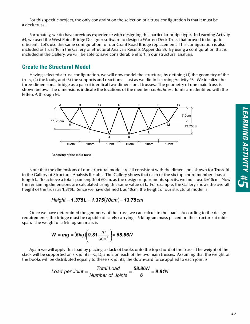
Create the Structural ModelHaving selected a truss configuration, we will now model the structure, by defining (1) the geometry of the
truss, (2) the loads, and (3) the supports and reactions—just as we did in Learning Activity #3. We idealize the three-dimensional bridge as a pair of identical two-dimensional trusses. The geometry of one main truss is shown below. The dimensions indicate the locations of the member centerlines. Joints are identified with the letters A through M.
Note that the dimensions of our structural model are all consistent with the dimensions shown for Truss 16 in the Gallery of Structural Analysis Results. The Gallery shows that each of the six top chord members has a length L. To achieve a total span length of 60cm, as the design requirements specify, we must use L=10cm. Now the remaining dimensions are calculated using this same value of L. For example, the Gallery shows the overall height of the truss as 1.375L. Since we have defined L as 10cm, the height of our structural model is
Once we have determined the geometry of the truss, we can calculate the loads. According to the design requirements, the bridge must be capable of safely carrying a 6-kilogram mass placed on the structure at mid-span. The weight of a 6-kilogram mass is
Again we will apply this load by placing a stack of books onto the top chord of the truss. The weight of the stack will be supported on six joints—C, D, and E on each of the two main trusses. Assuming that the weight of the books will be distributed equally to these six joints, the downward force applied to each joint is
Geometry of the main truss.
5-8
Note that we could have gotten this same result directly from the Gallery of Structural Analysis Results. The diagram for Truss 16 shows that a downward load of 0.1667W is applied to each of the three center top-chord joints. For a total load W=58.86N, the load at each joint is
A complete free body diagram of the truss looks like this:
Free body diagram of the main truss.
The bridge will be supported only at its ends; thus, the reactions RA and RG are shown at Joints A and G.
Check Static Determinacy and StabilityBefore we can use the equations of equilibrium to analyze a truss, we must first verify that it is statically
determinate and stable. As we saw in Learning Activity #3, the mathematical condition for static determinacy and stability is
where j is the number of joints and m is the number of members. Our structural model has 13 joints and 23 members. Substituting these numbers into the equation above, we find that 2j and m+3 are both equal to 26, so the mathematical condition for static determinacy and stability is satisfied.
Calculate ReactionsNow we can begin the structural analysis of our truss by calculating its unknown reactions. Since all loads
and reactions act in the vertical direction, we can use the sum of forces in the y-direction (ΣFy) to find the unknown reactions RA and RG.
LEARN
ING
ACTIVITY #5
5-9
Since the structure, the loads, and the reactions are all symmetrical about the centerline of the truss, the two reactions RA and RG must be equal. Substituting RA = RG into the equilibrium equation above, we get
And since RA = RG, then
Note once again that we could have gotten this same result directly from the Gallery of Structural Analysis Results. The diagram for Truss 16 indicates that each reaction has a magnitude of 0.25W. For a total load W=58.86N, each reaction is
Calculate Internal Member ForcesAt this point in the design process, we must determine the internal force in each member of the truss. As
long as the truss is statically determinate, we can always calculate internal member forces by applying the Method of Joints, just as we did in Learning Activity #3. However, when we use a truss configuration from the Gallery of Structural Analysis Results, we can determine these forces with considerably less effort.
Each truss in the Gallery is presented with a complete set of internal member forces, calculated for the loading shown. The internal forces are shown in terms on the total applied load W. To determine the internal member forces for our specific loading, we just substitute W=58.86N for each member. For example, the Gallery indicates that Member AB in our structural model has an internal force of -0.167W. Therefore, the force in Member AB (FAB) is
Similarly, the Gallery shows that the internal force in Members CD and AH are –0.394W and +0.301W. Therefore,
Recall that a minus sign indicates compression, while a plus sign indicates tension.
5-10
Determine Member Sizes Now we will determine the size of each member in our structure. Our objective is to ensure that each
member is strong enough to safely carry its internal force. If the internal force is compression, we’ll use a tube for the member. If the internal force is tension, we’ll use a doubled bar, just as we did on the original Grant Road Bridge in Learning Activity #1.
TubesMember AB carries load in compression, so we will use a tube for this member. To determine the required
size of the tube, we will use the compressive strength vs. length graph we created in Learning Activity #2. That graph is shown below.
QQ1Can you calculate the remaining internal member forces?
Use the Gallery of Structural Analysis Results to calculate the internal member forces for all remaining members in our truss. Use a total load W=58.86N.
Selecting the required tube size is a four-step process:
1) Determine the member length. Member AB is 10cm long.
2) Calculate the required strength, using the equation
The design requirements specify that the factor of safety will be 2.0, and above we determined that the internal member force FAB is 9.83N (compression). So the required strength is
Selecting the required tube size for Member AB.
0
10
20
30
40
50
60
0 2 4 6 8 10 12 14 16 18
Length (cm)
10mm x 10mm tube
6mm x 10mm tube
19.7
10
Required Strength = 19.7N
Actual Strength = 45N
1
2 3
4
0
10
20
30
40
50
60
0 2 4 6 8 10 12 14 16 18
Length (cm)
Com
pres
sive
Str
engt
h (n
ewto
ns)
10mm x 10mm tube
6mm x 10mm tube
19.7
10
Required Strength = 19.7N
Actual Strength = 45N 45
1
2 3
4
LEARN
ING
ACTIVITY #5
5-11
This calculation tells us that Member AB must be a tube with a compressive strength of at least 19.7 newtons.
3) Now plot the point corresponding to Length=10cm and the Strength=19.7N, as shown above.
4) Finally determine the smallest available tube size that has a strength larger than 19.7 for the same length. To do this, start at the point you plotted in Step 3, and draw a line straight upward to the closest strength curve. In this case, a 6mm x 10mm tube with a length of 10cm has a compressive strength of about 45 newtons—considerably greater than the required strength of 19.7N. Therefore, we can safely use a 6mm x 10mm tube for Member AB.
Note that we also could use a 10mm x 10mm tube for Member AB. With a compressive strength of about 50 newtons, this member is even stronger than the 6mm x 10mm tube—but quite a bit stronger (and more expen-sive) than it really needs to be. Note also that we could probably use a tube that is considerably smaller than 6mm x 10mm, except that we have no test data available for any smaller member sizes. Any tube with a com-pressive strength greater than 19.7N for a 10cm length would be perfectly acceptable for Member AB.
Whatever member size we decide to use for Member AB, we should use the same one for its twin, Member FG on the opposite side of the truss. Members AB and FG have the same internal force and the same length, so they should use the same member size. By taking advantage of symmetry in this manner, we can save a lot of work, because we only really need to determine member sizes for half of the members in the truss.
Now let’s use the same procedure for Member CD. Like Member AB, the length of Member CD is 10cm. Its required strength is
When we plot Length=10cm and Strength=46.4N on the graph, the point falls between the two strength curves, as shown below. Therefore, the 6mm x 10mm tube, with its compressive strength of 45N, is not strong enough for Member CD. Only the 10mm x 10mm tube will work, because its actual strength of 50N exceeds to required strength. We will use a 10mm x 10mm tube for Member CD and for its twin, Member DE.
Selecting the required tube size for Member CD.
0
10
20
30
40
50
60
0 2 4 6 8 10 12 14 16 18
Length (cm)
10mm x 10mm tube
6mm x 10mm tube
46.4
10
Required Strength = 46.4N
Actual Strength = 50N 50
0
10
20
30
40
50
60
0 2 4 6 8 10 12 14 16 18
Length (cm)
Com
pres
sive
Str
engt
h (n
ewto
ns)
10mm x 10mm tube
6mm x 10mm tube
46.4
10
Required Strength = 46.4N
Actual Strength = 50N 50
5-12
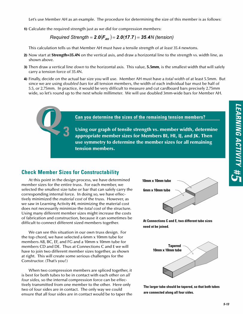
The sizes of the remaining compression members can be determined in exactly the same manner. The only aspect of this process that presents a new challenge is finding the lengths of the diagonal members. Consider Member BH as an example. If we visualize this member as the hypotenuse of a right triangle, as shown here, then we can use the Pythagorean theo-rem to find its length, BH:
This is Step 1 of the four-step process. Once you have determined the length BH, you can complete the remaining three steps exactly as we did above.
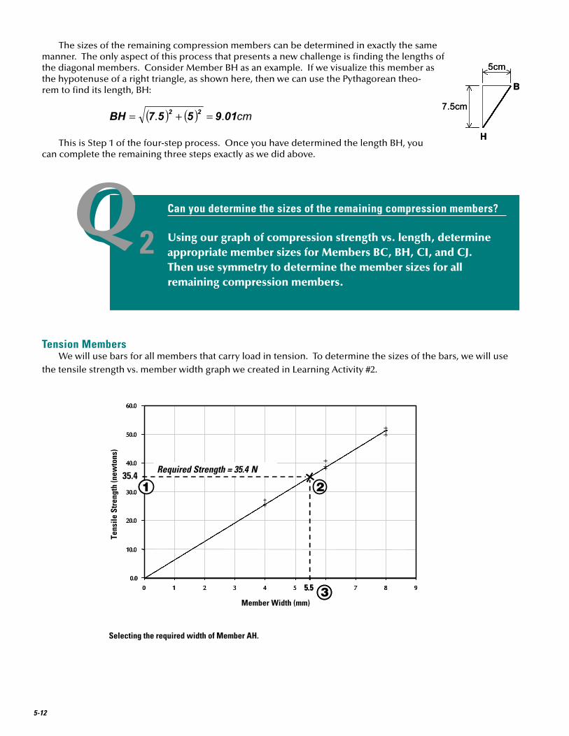
Tension MembersWe will use bars for all members that carry load in tension. To determine the sizes of the bars, we will use
the tensile strength vs. member width graph we created in Learning Activity #2.
QQ2Can you determine the sizes of the remaining compression members?
Using our graph of compression strength vs. length, determine appropriate member sizes for Members BC, BH, CI, and CJ. Then use symmetry to determine the member sizes for all remaining compression members.
Selecting the required width of Member AH.
0.0
10.0
20.0
30.0
40.0
50.0
60.0
0 1 2 3 4 5 6 7 8 95.5
Required Strength = 35.4 N
1 2
30.0
10.0
20.0
30.0
40.0
50.0
60.0
0 1 2 3 4 5 6 7 8 9
0.0
10.0
20.0
30.0
40.0
50.0
60.0
0 1 2 3 4 5 6 7 8 9
Member Width (mm)
Tens
ile S
tren
gth
(new
tons
)
35.4
5.5
Required Strength = 35.4 N
1 2
3
LEARN
ING
ACTIVITY #5
5-13
Let’s use Member AH as an example. The procedure for determining the size of this member is as follows:
1) Calculate the required strength just as we did for compression members:
This calculation tells us that Member AH must have a tensile strength of at least 35.4 newtons.
2) Now start at Strength=35.4N on the vertical axis, and draw a horizontal line to the strength vs. width line, as shown above.
3) Then draw a vertical line down to the horizontal axis. This value, 5.5mm, is the smallest width that will safely carry a tension force of 35.4N.
4) Finally, decide on the actual bar size you will use. Member AH must have a total width of at least 5.5mm. But since we are using doubled bars for all tension members, the width of each individual bar must be half of 5.5, or 2.75mm. In practice, it would be very difficult to measure and cut cardboard bars precisely 2.75mm wide, so let’s round up to the next whole millimeter. We will use doubled 3mm-wide bars for Member AH.
QQ3Can you determine the sizes of the remaining tension members?
Using our graph of tensile strength vs. member width, determine appropriate member sizes for Members BI, HI, IJ, and JK. Then use symmetry to determine the member sizes for all remaining tension members.
10mm x 10mm tube
6mm x 10mm tube
Tapered10mm x 10mm tube
At Connections C and E, two different tube sizes
need ot be joined.
The larger tube should be tapered, so that both tubes
are connected along all four sides.
Check Member Sizes for ConstructabilityAt this point in the design process, we have determined
member sizes for the entire truss. For each member, we selected the smallest size tube or bar that can safely carry the corresponding internal force. In doing so, we have effec-tively minimized the material cost of the truss. However, as we saw in Learning Activity #4, minimizing the material cost does not necessarily minimize the total cost of the structure. Using many different member sizes might increase the costs of fabrication and construction, because it can sometimes be difficult to connect different sized members together.
We can see this situation in our own truss design. For the top chord, we have selected a 6mm x 10mm tube for members AB, BC, EF, and FG and a 10mm x 10mm tube for members CD and DE. Thus at Connections C and E we will have to join two different member sizes together, as shown at right. This will create some serious challenges for the Constructor. (That’s you!)
When two compression members are spliced together, it is best for both tubes to be in contact with each other on all four sides, so the internal compression force can be effec-tively transmitted from one member to the other. Here only two of four sides are in contact. The only way we could ensure that all four sides are in contact would be to taper the
5-14
end of 10mm x 10mm tube, as shown. Building this joint will take a lot of time, and building it well will be quite difficult. Furthermore, recall that in Learning Activity #1, we attached the two main trusses together by placing them upside down on the lateral bracing subassembly, which was pinned to the building board. That procedure won’t work if the top surface of the top chord is not entirely at the same elevation.
For these reasons, we can greatly simplify the construction of our bridge by using 10mm x 10mm tubes for all top chord members. As a result, Members AB, BC, EF, and FG will be considerably stronger—and somewhat more expensive—than they really need to be. But the benefits gained from using a single tube size for the entire top chord will greatly outweigh the small additional cost of using four slightly oversized members.
Draw PlansHaving decided what the size of each truss member should be, we’re now ready to draw the plans. Specifi-
cally, we will create the full-scale layout drawing on which we will actually build the main trusses and lateral bracing subassembly for the Grant Road Bridge. In Learning Activity #1 this drawing was provided to you. Now you’re smart enough to do it yourself!
Before you can create the drawing, get the necessary tools and supplies. First, you’ll need a big sheet of paper—at least 30 centimeters wide and 65 centimeters long. Craft paper, shelf paper, or even wrapping paper will work fine. You’ll also need a metric ruler, a sharp pencil, and an eraser to do the drawing.
If available, a drawing board, a T-square, and some draftsman’s triangles will also be very helpful. These tools will help you to draw parallel and perpendicular lines accurately. If these tools are not available, it would be a good idea to do your drawings on graph paper. Try to find graph paper that is large enough to do the entire drawing on one sheet. Your local office supply store might have large-size graph
paper. If not, tape several standard-size sheets together, being very careful to ensure that all of the grid lines on adjacent sheets are aligned.
As an alternative, if you have access to appropriate computer-aided drawing software and know how to use it, you can use a computer to do the layout drawing. (The layout drawing we used in Learning Activity #1 was done entirely by computer.) But if you decide to use a computer, you must ensure that you have the right software and the right hardware to do the job. First, the software must be a true technical drawing or computer-aided drafting package like AutoCAD, IntelliCAD, or TurboCAD. Presentation graphics programs like Pow-erPoint are not appropriate for this job, because they don’t provide the necessary degree of precision. Second, you must have access to a printer or plotter capable of producing a full-scale hard copy of your drawing.
Once all of the necessary supplies and tools are on hand, tape the paper to your drawing board or to a smooth flat tabletop. Now sharpen your pencil, and let’s get to work.
LEARN
ING
ACTIVITY #5
5-15
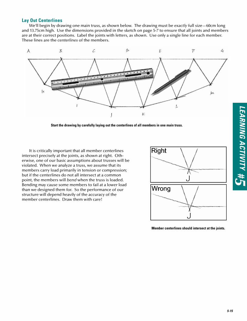
Start the drawing by carefully laying out the centerlines of all members in one main truss.
Member centerlines should intersect at the joints.
Lay Out CenterlinesWe’ll begin by drawing one main truss, as shown below. The drawing must be exactly full size—60cm long
and 13.75cm high. Use the dimensions provided in the sketch on page 5-7 to ensure that all joints and members are at their correct positions. Label the joints with letters, as shown. Use only a single line for each member. These lines are the centerlines of the members.
It is critically important that all member centerlines intersect precisely at the joints, as shown at right. Oth-erwise, one of our basic assumptions about trusses will be violated. When we analyze a truss, we assume that its members carry load primarily in tension or compression; but if the centerlines do not all intersect at a common point, the members will bend when the truss is loaded. Bending may cause some members to fail at a lower load than we designed them for. So the performance of our structure will depend heavily of the accuracy of the member centerlines. Draw them with care!
5-16
Draw MembersNow we will draw the truss members, using the member sizes we determined earlier in the design process.
Let’s use Member CJ as an example. Begin by placing your ruler perpendicular to the member centerline, as shown in A. Make two pencil marks to indicate the actual width of the member. Since Member CJ is a 6mm x 10mm tube, the two marks should be 6mm apart. Each mark should be 3mm from the centerline. Then make an identical pair of marks at the opposite end of the same member. Finally, use your ruler to draw two parallel lines connecting the marks, as shown in B. These two lines represent the outer edges of Member CJ. If you measure accurately and draw your lines carefully, the centerline will be exactly midway between the two edges.
Now let’s follow this same procedure to draw Member CD, a top chord. Since this member is a 10mm x 10mm tube, the pairs of pencil marks shown in C are 10mm apart, with each mark located 5mm from the centerline. Again, we draw the edges of the member by “connect the dots” with two parallel lines, as shown in D. Since the entire top chord is made of identical 10mm x 10mm tubes, we can actu-ally draw the edges of the chord as two continu-ous lines running all the way from Joint A to joint G.
With all members drawn, the truss layout should look like this.
Layout drawing of the main truss with all members completed.
To draw a member, first mark its width (A), then draw two parallel lines (B).
Use the same procedure to draw the top chord.
A B
C D
LEARN
ING
ACTIVITY #5
5-17
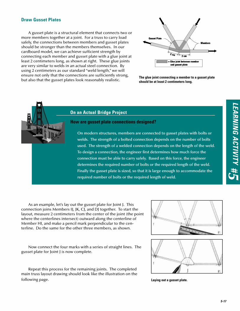
Draw Gusset Plates
A gusset plate is a structural element that connects two or more members together at a joint. For a truss to carry load safely, the connections between members and gusset plates should be stronger than the members themselves. In our cardboard model, we can achieve sufficient strength by connecting each member and gusset plate with a glue joint at least 2 centimeters long, as shown at right. These glue joints are very similar to welds in an actual steel connection. By using 2 centimeters as our standard “weld length,” we will ensure not only that the connections are sufficiently strong, but also that the gusset plates look reasonably realistic.
The glue joint connecting a member to a gusset plate should be at least 2 centimeters long.
2 cm2 cm
Gusset Plate
Members
= Glue joint between member and gusset plate
2 cm2 cm
Gusset Plate
Members
= Glue joint between member and gusset plate
Laying out a gusset plate.
On an Actual Bridge Project
How are gusset plate connections designed?
On modern structures, members are connected to gusset plates with bolts or
welds. The strength of a bolted connection depends on the number of bolts
used. The strength of a welded connection depends on the length of the weld.
To design a connection, the engineer first determines how much force the
connection must be able to carry safely. Based on this force, the engineer
determines the required number of bolts or the required length of the weld.
Finally the gusset plate is sized, so that it is large enough to accommodate the
required number of bolts or the required length of weld.
As an example, let’s lay out the gusset plate for Joint J. This connection joins Members IJ, JK, CJ, and DJ together. To start the layout, measure 2 centimeters from the center of the joint (the point where the centerlines intersect) outward along the centerline of Member HI, and make a pencil mark perpendicular to the cen-terline. Do the same for the other three members, as shown.
Now connect the four marks with a series of straight lines. The gusset plate for Joint J is now complete.
Repeat this process for the remaining joints. The completed main truss layout drawing should look like the illustration on the following page.
5-18
Layout drawing of the main truss with all members completed.
Note that the gusset plates at Joints A and G have been squared off on the bottom and outside edges. The bottom edges of these two gusset plates will serve as the supports for the bridge. These edges should be perfectly horizontal and about 1.5 centimeters long, as shown below (left).
These gusset plates alone won’t be strong enough to support the bridge. Recall that we calculated the reactions at Joints A and G as 14.7 newtons each. Since these reactions are directed upward, they will cause compression in the gusset plates at A and G. These gussets are just flat sheets of cardboard; thus they will buckle with only a slight application of compressive force. To keep them from buckling, we’ll need to reinforce them with a short section of 10mm x 10mm tube oriented vertically, as shown below (right).
Reinforce the support with a short length of 10mm x 10mm tube oriented vertically.
The Gusset plates at Joints A and G
also serve as supports.
Member FG
Member GM
GussetPlate G
10mm x 10mmtube
GussetPlate G
Member FG
Member GM
GussetPlate G
10mm x 10mmtube
GussetPlate G
You may recall that the layout drawing we used in Learning Activity #1 included two identical copies of the main truss layout. With two copies available, we were able to build both halves of each truss simultaneously, resulting in a considerable time saving during construction. Of course, the drawing you used in Learning Activity #1 was done with a computer, so the second copy of the truss was easily created and guaranteed to be identical to the first. If you are doing your layout drawing by hand, it is best to use just one truss layout. If you try to draw a second copy by hand, it probably won’t be identical to the first, and the two halves of the truss won’t line up correctly. Just remember that, if you draw only one truss layout, you’ll need to use it four times—once for each half of the two main trusses.
LEARN
ING
ACTIVITY #5
5-19
Lay Out Top Lateral BracingThe layout drawing for our design must also include the top lateral bracing subassembly, shown below.
Begin by drawing the member centerlines, as we did for the main trusses. The centerlines of the two top chords should be 10 centimeters apart. This will ensure that the total width of the bridge, from one outside edge to the other, will be 11 centimeters—the roadway width specified in the design requirements. Because this bridge is a deck truss, the struts (Members AA’, BB’, CC’, and so forth) must also serve as floor beams. Thus we will use 6mm x 10mm tubes for these members, rather than the 6mm x 6mm tubes used for the struts in the original Grant Road Bridge. We’ll use single 3mm bars for the diagonal bracing.
Top Lateral Bracing Layout
Transfer Gusset PlatesNow that the layout drawing is complete, we’ll need to transfer the gusset plate outlines to file-folder
cardboard without cutting up the drawing. The easiest way to do this is with tracing paper. Place a sheet of tracing paper on top of the layout drawing, and trace the outline of each gusset plate onto the tracing paper. Then photocopy the tracing paper to transfer the gusset plate outlines onto cardboard, as described in Learning Activity #1 (Page 1-24).
As an alternative, you can also use carbon paper to do the transfer. Place a file folder beneath the layout drawing, with a sheet of carbon paper face down between the drawing and the file folder. Then carefully trace over the outline of each gusset plate to transfer it directly to the cardboard.
Actually, you don’t really need to transfer every gusset plate. On the main truss layout, note that Joint A is identical to Joint G; B is identical to F; H is identical to M; and so forth. You can transfer only the gusset plates at Joints A, B, C, D, H, J, and I, then make a set of identical copies for the corresponding joints on the opposite side of the truss. Similarly, on the lateral bracing subassembly, you only need to transfer the gusset plates at Joints A and B. All remaining gusset plates in the subassembly are identical to one or the other of these two.
Create a Schedule of Truss Members and a Schedule of Gusset PlatesThe Schedule of Truss Members is an important part of the plans and specifications for our bridge design. It
summarizes the type, size, and length of every structural member in the bridge and thus serves as an important reference for the Constructor. In formulating the schedule, we note that the 10mm x 10mm top chord is per-fectly straight from one end of the bridge to the other. Thus we could actually make each top chord from a single tube—if we could find a file folder 62 centimeters long. We can’t, of course, so we’ll have to build each top chord in three segments, each about 21 centimeters long. (If you use a legal size file folder, you can make the top chord in only two segments.)
5-20
The lengths provided in the Schedule of Truss Members are only approximate. The Constructor will cut them to their exact lengths as the trusses are built.
The Schedule of Gusset Plates shows the number of each type of gusset plate that will be used for the truss connections.
Component Members Type Approx. Length
# Req’d
Bottom Chords HI, LM, H’I’, L’M’ 3mm bar (double) 11cm 8 Bottom Chords IJ, JK, KL, I’J’, J’K’, K’L’ 4mm bar (double) 11cm 12 Diagonals AH, GM, A’H’, G’M’ 3mm bar (double) 10cm 8 Diagonals BI, FL, B’I’, F’L’ 2mm bar (double) 13cm 8 Top Lateral Bracing
Top Chords AC, CE, EG, A’C’, C’E’, E’G’ 10mm x 10mm tube 21cm 6 Diagonals BH, FM, B’H’, F’M’ 6mm x 10mm tube 9cm 4 Diagonals CI, EL, C’I’, E’L’ 6mm x 10mm tube 13cm 4 Diagonals CJ, EK, C’J’, E’K’ 6mm x 10mm tube 15cm 4 Diagonals DJ, DK, D’J’, D’K’ 6mm x 10mm tube 15cm 4 Floor Beams AA’, BB’, CC’, DD’, E E’, FF’, GG’ 6mm x 10mm tube 10cm 7 Bottom Struts HH’, II’, JJ’, KK’, LL’, MM’ 6mm x 6mm tube 10cm 6
Connection # Req’d
A, A’, G, G’ 8 B, B’, F, F’ 8 C, C’, E, E’ 8 D, D’ 4 H, H’, M, M’ 8 I, I’, L, L’ 8 J, J’, K, K’ 8 A, A’, G, G’ (top) 4 B, B’, C, C’, D, D’, E, E’, F, F’ (top) 10
Build the BridgeThe plans and specifications for the new Grant Road Bridge are complete. If this were a traditional design-
bid-build project, your work as the Design Professional would be mostly done. You would present your com-pleted design to the Owner, who would then procure a Constructor through competitive bidding. But because we are using design-build project delivery, you have full responsibility for both design and construction.
LEARN
ING
ACTIVITY #5
5-21
There’s no time to waste. The residents of Hauptville are anxious to have Grant Road reopened to traffic. It’s up to you to make it happen.
To build the new Grant Road Bridge, follow the same procedure we used in Learning Activity #1. The result should look like the photo below.
Once you have completed your quality control inspection, place the bridge on two desks positioned 58 centimeters apart. Place six coins on the top chord at Connections C, C’, D, D’, E, and E’. Then place books one at a time on top, until the total mass of the stack is 6 kilograms. The new Grant Road Bridge is now open for traffic. Congratulations of the successful completion of the project!
The completed bridge model.
The completed Grant Road Bridge, with 6-kilogram loading in place.
5-22
ConclusionIn this learning activity, we “put it all together.” We applied scientific principles, mathematic tools, engineer-
ing concepts, experimental data, and practical considerations to design a truss bridge. Our design was carefully tailored to meet the needs of the Town of Hauptville, to be safe, to be constructable, and to be aesthetically pleasing. We validated the design by building and testing it—and it worked!
We conclude this project—and this book—with a strong sense of accomplishment, not only for the bridge we designed and built, but also for the skills we acquired along the way. Learning engineering isn’t easy, but learning engineering is worth every ounce of effort you put into it. To learn engineering is to open a new door—one that leads to a world of limitless possibilities for creative accomplishment and service to society. The door is now open. But how do you enter?
Every bridge begins in the mind of an engineer. There’s probably one in your mind right now. Build it!
QQ4How are math, science, and computer technology used in the engineering design process?
How did mathematical tools, scientific principles, and computer technology contribute to the creation of our design for the Grant Road Bridge? Give at least two examples in each area.
LEARN
ING
ACTIVITY #5
5-23
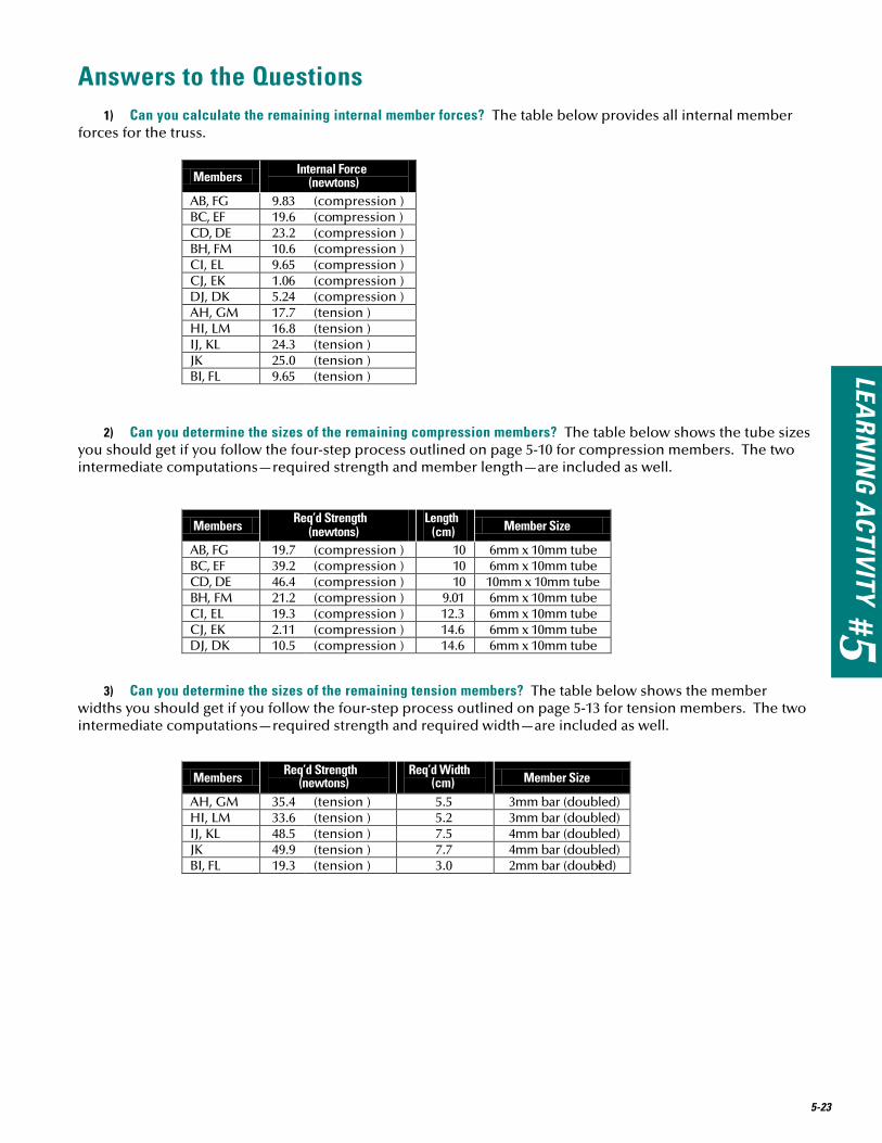
Answers to the Questions 1) Can you calculate the remaining internal member forces? The table below provides all internal member
forces for the truss.
Members Internal Force (newtons)
AB, FG 9.83 (compression ) BC, EF 19.6 (compression ) CD, DE 23.2 (compression ) BH, FM 10.6 (compression ) CI, EL 9.65 (compression ) CJ, EK 1.06 (compression ) DJ, DK 5.24 (compression ) AH, GM 17.7 (tension ) HI, LM 16.8 (tension ) IJ, KL 24.3 (tension ) JK 25.0 (tension ) BI, FL 9.65 (tension )
Members Req’d Strength (newtons)
Length (cm) Member Size
AB, FG 19.7 (compression ) 10 6mm x 10mm tube BC, EF 39.2 (compression ) 10 6mm x 10mm tube CD, DE 46.4 (compression ) 10 10mm x 10mm tube BH, FM 21.2 (compression ) 9.01 6mm x 10mm tube CI, EL 19.3 (compression ) 12.3 6mm x 10mm tube CJ, EK 2.11 (compression ) 14.6 6mm x 10mm tube DJ, DK 10.5 (compression ) 14.6 6mm x 10mm tube
Members Req’d Strength (newtons)
Req’d Width (cm) Member Size
AH, GM 35.4 (tension ) 5.5 3mm bar (doubled) HI, LM 33.6 (tension ) 5.2 3mm bar (doubled) IJ, KL 48.5 (tension ) 7.5 4mm bar (doubled) JK 49.9 (tension ) 7.7 4mm bar (doubled) BI, FL 19.3 (tension ) 3.0 2mm bar (doubled)
2) Can you determine the sizes of the remaining compression members? The table below shows the tube sizes you should get if you follow the four-step process outlined on page 5-10 for compression members. The two intermediate computations—required strength and member length—are included as well.
3) Can you determine the sizes of the remaining tension members? The table below shows the member widths you should get if you follow the four-step process outlined on page 5-13 for tension members. The two intermediate computations—required strength and required width—are included as well.
5-24
4) How are math, science, and computer technology used in the engineering design process?
We used the following mathematical tools to develop our design:
n The Pythagorean Theorem – to find the lengths of diagonal truss members.
n Trigonometry – to write equations of equilibrium in our structural analysis.
n Algebra – to solve equilibrium equations for unknown internal member forces.
n Vectors – to represent forces in our structural model.
We applied the following scientific principles and concepts to develop our design:
n Force – to represent loads, reactions, and internal member forces.
n Compression and tension – to represent the direction of internal member forces.
n Equilibrium – to calculate reactions and internal member forces.
n Relationship between force and mass – to convert the load from kilograms to newtons.
We used computer technology to develop our design, as follows:
n Spreadsheet – to analyze and graph the experimental data from strength testing.
n The West Point Bridge Designer – to find an efficient truss configuration.
n Computer-aided drafting software – to draw the plans (an alternative to drawing by hand).
Some Ideas for Enhancing This Learning ActivityThe best way to enhance this learning activity is to provide students with many and varied opportunities to
design and build bridges. If the students do not have the algebra or trigonometry background necessary to do a truss analysis using the Method of Joints, then their choices for truss configurations must necessarily be limited to those provided in the Gallery of Structural Analysis Results (Appendix B). If students do have the mathematical skills to apply the Method of Joints, then they can design bridges of practically any span or con-figuration.
It can be particularly effective to combine Learning Activities #4 and #5 into a single project. Students begin by designing a 24-meter bridge with the West Point Bridge Designer. Once they have found an efficient or interesting truss configuration, they design and build a 1/40th scale model of the same structure, using the procedures described in Learning Activity #5. This two-phase project uses the computer in the role for which it is best suited—exploring many different design alternatives relatively efficiently. But it also ensures that stu-dents do not merely use the computer as a “black box.” By working though the design of the 1/40th scale model manually, they gain an appreciation for the challenging mathematical calculations the computer performs so effortlessly.