8/27/2015 1 ET 438a Automatic Control Systems Technology 1 lesson4et438a.pptx Learning Objectives lesson4et438a.pptx 2 After this presentation you will be able to: Develop mathematical relationships for a sensor that has a linear output. Convert linear mathematical equations into block diagrams that represent sensor scaling circuits. Adjust the output range of a sensor using operational amplifier circuits.
Transcript
8/27/2015
1
ET 438a
Automatic Control Systems Technology
1lesson4et438a.pptx
Learning Objectives
lesson4et438a.pptx 2
After this presentation you will be able to:
Develop mathematical relationships for a sensor that has a linear output.
Convert linear mathematical equations into block diagrams that represent sensor scaling circuits.
Adjust the output range of a sensor using operational amplifier circuits.
8/27/2015
2
Scaling Sensor Outputs
lesson4et438a.pptx 3
x= transducer input(measured value)
VT = transducer outputvoltage
KT = transducer gain(slope)
Ks = scalar gainVs = scalar output
x1 x2
VT2
VT1
KT
x
VT
KS
ST
o
i
= =output span
input span
Span = max. value - min. value
Sensor Scaling Case 1: No Offset in Scalar or
Sensor
lesson4et438a.pptx 4
Transducer gain formula: VT = KTx
Required scalar gain:
KS
Ss
d
T
= =desired span
transducer span
V K K xs s T= ⋅ ⋅
Scalar output formula
V K Vs s T= ⋅
x
VT
Ks
KT
SensorKT
Block Diagram
ScalarKs
VT Vs
Input OutputVT = KTx Vs = KsVT
x
8/27/2015
3
Example 4-1: Case 1 Sensor
lesson4et438a.pptx 5
A pressure transducer has a usable range P (x) range of 0-50 psig (lb/in2
gauge). It has a voltage output range of 0-1.25 Vdc over the pressure range. Scale the output to a range of 0-10 Vdc
Find KTi
oT
S
S
spaninput
spanoutput K == V/psig 025.0
psig 050
V 025.1KT =
−−
=
Find scalar gainT
ds
S
S
span transducer
span desiredK == V/V 8
V 025.1
V 010K s =
−−
=
KT=0.025 V/psig
Ks=8 V/VVT VsP
Sensor Scaling Case 2: Offset in Sensor No
Offset in Output
lesson4et438a.pptx 6
KT
Ks
Sensor gain formula: VT = KTx + b
Where b = transducer offset
Scalar gain formula must subtract offset
bKVKV
xKKV
bKbKxKKV
bK)bxK(KV
sTss
Tss
ssTss
sTss
−=
=
−+=
−+=Correctform of scalar output
Scalar equation
x
VT
b
Block diagram
SensorKT∙x+b
ScalarKs∙VT- Ks∙ b
VT Vsx
VT=KT∙x+b Vs=Ks∙VT- Ks∙ b
8/27/2015
4
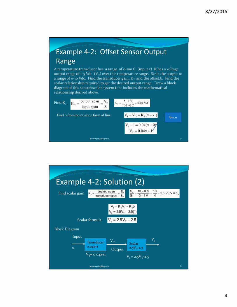
Example 4-2: Offset Sensor Output
Range
lesson4et438a.pptx 7
A temperature transducer has a range of 0-100 C (input x) It has a voltage output range of 1-5 Vdc (VT) over this temperature range. Scale the output to a range of 0-10 Vdc. Find the transducer gain, KT, and the offset,b. Find the scalar relationship required to get the desired output range. Draw a block diagram of this sensor/scalar system that includes the mathematical relationship derived above.
Find KT
i
oT
S
S
spaninput
spanoutput K == V/C 04.0
C 0 - 100
V 15KT =
−=
Find b from point slope form of line )xx(KVV 1T1TT −=−
1x04.0V
)0x(04.01V
T
T
+=
−=−
b=1.0
Example 4-2: Solution (2)
lesson4et438a.pptx 8
Find scalar gain KS
Ss
d
T
= =desired span
transducer span
S
Sd
T
=−−
= =10 0
5 1
10
42 5
V
V V / V = K s.
V K V K b
V V
s s T s
s T
= −
= −2 5 2 5 1. . ( )
Scalar formula V Vs T= −2 5 2 5. .
Transducer 0.04x+1
VT= 0.04x+1
x
VTVs
Input
Output
Scalar2.5VT-2.5
Vs = 2.5VT-2.5
Block Diagram
8/27/2015
5
Sensor Scaling Case 3: Transducer with
no offset, Output offset
lesson4et438a.pptx 9
KT
Ks
VT
x
c = scalar offset can be +- value
Transducer gain formula:VT = KTx
Scalar formula must add a constant
cVKV Tss +=
T
ds
S
S
span transducer
span desiredK ==
To find c, use point slope form using scalar points
)VV(KVV 1TTs1ss −=−
c
Example 4-3: Case 3 Sensor Scaling
lesson4et438a.pptx 10
A pressure transducer has an input range of 0 - 25 psig (x) and an output range of 0 - 1 V (VT) Find the scaling equation to convert this range into the desired range of -5 V to +5 Vdc) Find transducer gain and scalar gain formulas. Draw the block diagram of the complete system
Find KT KS
ST
o
i
= =output span
input spanKT =
−=
1 0004
V
25 - 0 psig V / psig.
Find Ks KS
Ss
d
T
= =desired span
transducer span
S
Sd
T
=− −−
= =5 5
1 0
10
110
( ) V
V V/ V=Ks
8/27/2015
6
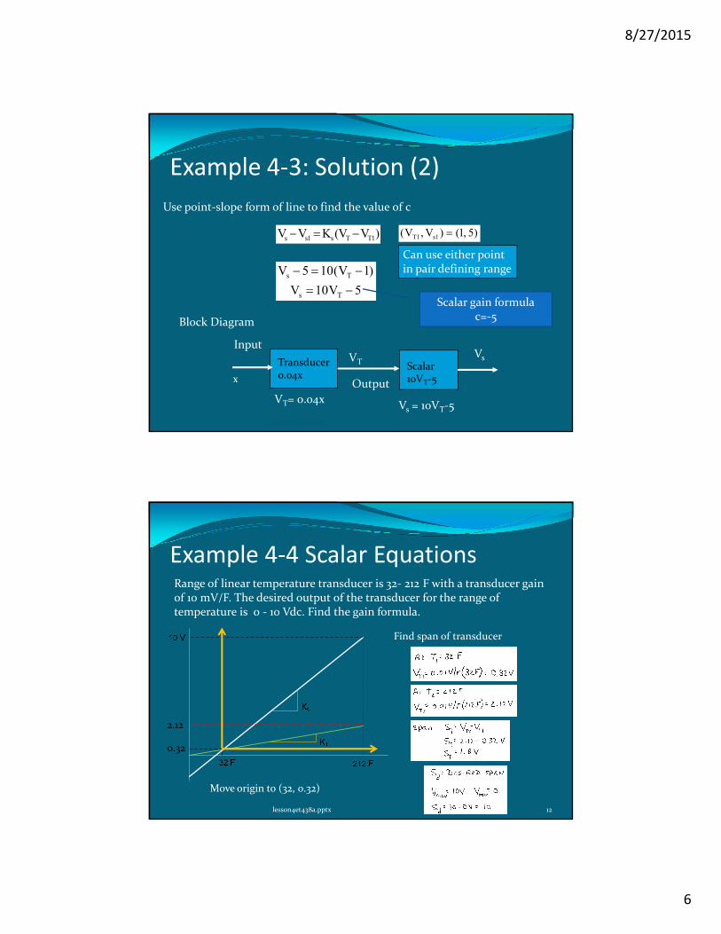
Example 4-3: Solution (2)
lesson4et438a.pptx 11
Use point-slope form of line to find the value of c
)VV(KVV 1TTs1ss −=− 5) ,1()V,V( 1s1T =
Can use either pointin pair defining range
5V10V
)1V(105V
Ts
Ts
−=
−=−
Scalar gain formulac=-5
Transducer 0.04x
VT= 0.04x
x
VTVs
Input
Output
Scalar10VT-5
Vs = 10VT-5
Block Diagram
Example 4-4 Scalar Equations
lesson4et438a.pptx 12
Range of linear temperature transducer is 32- 212 F with a transducer gain of 10 mV/F. The desired output of the transducer for the range of temperature is 0 - 10 Vdc. Find the gain formula.
A linear temperature transducer has an input range of -20 C to 50 C and a gain of KT = 20 mV/C. The desired output range is 0 - 5 Vdc. The transducer output voltage is bipolar (+-). Find the scaling equation.
Compute the transducer and scalar span
Scalar formula
Find b graphically. Must shift origin to(-20 C, -0.4 V)
Example 4-5 Solution (2)
lesson4et438a.pptx 16
Find scalar gain Check scalar equation at data points
Transducer 0.02x
VT= 0.02T
T
VTVs
InputTemp
Output
Scalar3.571VT-1.429
Vs = 3.571VT-1.429
Block Diagram
8/27/2015
9
Practical Realization of Scalar Equations
Using OP AMPs
lesson4et438a.pptx 17
Scaling without offset: use inverting or non-inverting amps to implement Ks
in
fs
R
RK
−=
For inverting amps
V0
Rf
Rin
Vcc
Sensor
+=
1
fs
R
R1K
For non-inverting amps
Practical Realization of Scalar Equations
Using OP AMPs
lesson4et438a.pptx 18
For transducers with offset use inverting and summation amps
Stage 2 OP AMP changes
sign if Rf1 = Rin AV = -1
Vs
Stage 1Stage 2
Rf
Rb
RT
Rf1
Vb
Rin
VT
b
b
fT
T
fo V
R
RV
R
RV
−+
−=
b
b
fT
T
fb
b
fT
T
fs V
R
RV
R
R)1(V
R
RV
R
RV +=−
−+
−=
Stage 1 Overall gain
8/27/2015
10
Practical Realization of Scalar Equations
Using OP AMPs
lesson4et438a.pptx 19
Equate the sensor with offset formula to the OP AMP gain derived on the last slide
( ) b
b
fT
T
fsTss V
R
RV
R
RbKVKV +=−= so b
b
fs
T
fs V
R
RbK
R
RK ==
Vs
Stage 1Stage 2
Rf
Rb
RT
Rf1
Vb
Rin
VT
Example 4-6: Implementing Scalar Equation
with OP AMPs
lesson4et438a.pptx 20
Design an OP AMP circuit that will implement the scalar equation from Example 4-5 Assume Rf1 = Rin = 100 kΩ Rf = 470 kΩ
V Vs T= +3 571 1429. .
Scalar relationship for Example 4-5
Vs
Stage 1Stage 2
Rf
Rb
RT
Rf1
Vb
Rin
VT
From scalar equationKs= 3.571
8/27/2015
11
Example 4-6: Solution (2)
lesson4et438a.pptx 21
Value of RT is not a standard value. Use a standard value near the computed value in series with a potentiometer and calibrate circuit. Use -0.4 and 1.0 V and adjust the potentiometer