27
Lecture #1 Page 1 ECE 4110– Digital SystemDesign
| Date post: | 28-Dec-2015 |
| Category: |
Documents |
| Upload: | jocelin-tyler |
| View: | 218 times |
| Download: | 0 times |

Lecture #1Page 1ECE 4110– Digital SystemDesign

ECE 4110– Digital System DesignLecture #1
Agenda
1. Course Logistics2. Course Content3. Digital Review
Announcements
1. Welcome2. Homework #1 assigned
Lecture #1Page 2
Course Overview Instructor: Omar Elkeelany Office : 332 Brown Hall
Phone : (931)-372-3450Email :
[email protected] Web :http://iweb.tntehc.edu/oelkeelany
Lecture #1Page 3
Course Overview Textbook: “Digital Design: Principles and
Practices", 4th Addition
John F. Wakerly, Prentice Hall, 2006
Website:http://iweb.tntech.edu/oelkeelany/4110F13 all handouts, homework assignments are
ONLINE it is your responsibility to download assignments
Lecture #1Page 4

Course Overview Pre-requisites: ECE2110 / ECE3160
Grading: Homework/VHDL and Quizzes 20%Combo System project 20%Exam #1 20% Exam #2 20% Final Exam 20%
- Homework Assignments are due at the beginning of class.
- No Late homework will be accepted.
- No make up exams will be given, unless pre-excuesd before the test.
Plan on being available on the exam dates.
- Term paper assignment will be given for 5110 graduate level.
Lecture #1Page 5

Course OverviewWhere does this course fit into the Electrical Engineering
curriculum?
Lecture #1Page 6

Course Overview Where does this course fit into the Computer
Engineering curriculum?
Lecture #1Page 7

Course Content What is this course?
- In ECE2110 you learned: - basic combinational logic design - basic sequential logic design
- In ECE3160 you learned:
- how to implement logic circuits using off-the-shelf parts
- ECE4110 is a follow-on course that looks at:
- Large scale digital designs - Performance of digital circuitry - Programmable Logic
Lecture #1Page 8

Course Content What does "Large" mean?
- Large means that you can't do it by hand. We need a way to design and simulate Millions of gates
- K-maps for a Pentium would take too much paper
Lecture #1Page 9

Course Content We will learn VHDL in order to describe large digital designs
- VHDL is a text based Hardware Description Language
- We can simulate our digital designs created in VHDL
Lecture #1Page 10

Course Content We can also prototype our designs using an FPGA
- FPGA = Field Programmable Gate Array
- An FPGA is a programmable logic device
- In this course, we will implement our designs and test them in FPGA
hardware
Lecture #1Page 11

Course Content What topics will be covered?
1) VHDL (Exam #1 Topics)
2) Medium Scale Combinational Logic Devices3) More Complex Finite State Machines (Exam #2
Topics) 4) Computer Systems5) FPGA Timing and Implementation
For the 5110 level, a special assignment is to: Write an original research paper on a topic related to those in this course, such as:
Modern programmable logic devices, survey, features, comparisons, usage, etc.. Hardware description languages: survey, comparisons, usage, IP, etc. Sequential Logic Design methods
Lecture #1Page 12

Lecture #1Page 13
Digital Review
Combinational Logic
Combinational Logic Gates :
- Output depends on the logic value of the inputs
- no storage

Lecture #1Page 14
Digital Review
NOT out = in’ = in f(in) = in’ = in
OR out = a+b f(a,b) = a+b
AND out = a·b f(a,b) = a·b

Lecture #1Page 15
Digital Review
XOR out = ab f(a,b) = ab
NOR out = a+b f(a,b) = a+b
NAND out = a·b f(a,b) = a·b

Lecture #1Page 16
Digital Review
XNOR out = ab f(a,b) = ab
Also remember about XOR Gates:
f(a,b) = ab = (a’b + b’a)
Also remember the priority of logic operations (without parenthesis) is:
NOT, AND, OR

Lecture #1Page 17
Digital Review
DeMorgan’s Theorems
- Inverting the output of any gate results in the same function as the opposite gate (AND/OR) with inverted inputs
Lecture #1Page 18
Digital Review
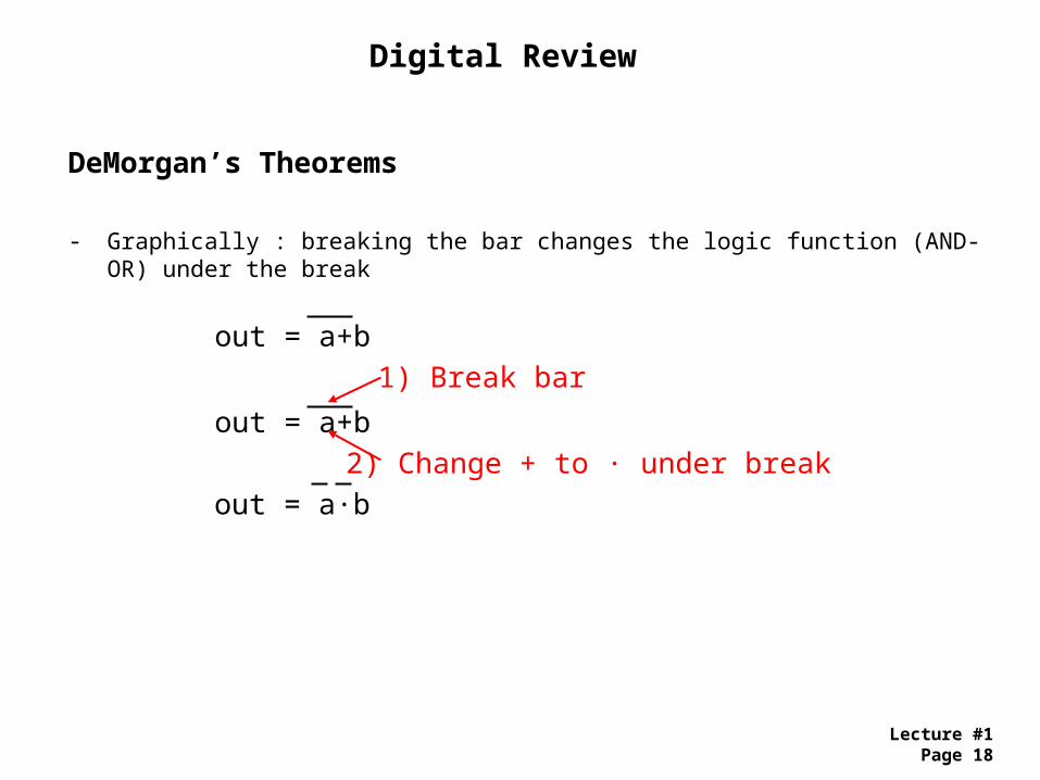
DeMorgan’s Theorems
- Graphically : breaking the bar changes the logic function (AND-OR) under the break
out = a+b
out = a+b
out = a·b
1) Break bar
2) Change + to · under break

Lecture #1Page 19
Digital Review
Boolean Expressions Using SOP
- Logic functions can be described using a Sum of Products techniques- Sum of Products (SOP) is the summation of all minterms resulting in the truth table- A minterm is the expression for an input configuration which yields a TRUE output- A minterm expression is the AND’ing of the input "1" signal configuration
SOP Expression : f(a,b) = a’·b + a·b’
Note : un-minimized Boolean expression
Truth Tablea b out0 0 00 1 1 minterm m1 = a’·b1 0 1 minterm m2 = a·b’1 1 0

Lecture #1Page 20
Digital Review
Boolean Expressions Using POS
- Logic functions can be described using a Product of Sums techniques- Product of Sums (POS) is the multiplication of all maxterms resulting in the truth table- A maxterm is the expression for an input configuration which yields a FALSE output- A maxterm expression is the OR’ing of the input "0" signal configuration
POS Expression : f(a,b) = (a+b) · (a'+b')
Truth Tablea b out0 0 0 maxterm m0 = a+b (input configuration of 0's)0 1 11 0 11 1 0 maxterm m3 = a'+b' (input configuration of 0's)

Lecture #1Page 21
Digital Review
Boolean Expressions Using SOP & POS
- SOP and POS functions are equivalent
SOP Expression : f(a,b) = a’·b + a·b’
is equal to
POS Expression : f(a,b) = (a+b) · (a'+b')

Lecture #1Page 22
Digital Review
Karnaugh Maps
- K-maps provide a graphical method to find SOP/POS expressions
- K-maps also provide a graphical method to perform logic minimization
K-map SOP Process
1) Circle minterms to create SOP
2) Circle in Horizontal & Vertical manner
3) Circle in groups with powers of 2 (1,2,4,8,…)
Truth Table
a b out0 0 00 1 11 0 11 1 1
0 1
1 1
a 0 1
b 0 1
No dependency on b, minterm = a
No dependency on a, minterm = b
SOP expression : f(a,b) = a + b

Lecture #1Page 23
Digital Review
Karnaugh Maps
- K-maps provide a graphical method to find SOP/POS expressions
- K-maps also provide a graphical method to perform logic minimization
K-map POS Process
1) Circle maxterms to create SOP
2) Circle in Horizontal & Vertical manner
3) Circle in groups with powers of 2 (1,2,4,8,…)
Truth Table
a b out0 0 00 1 11 0 11 1 1
0 1
1 1
a 0 1
b 0 1
Dependency on a' and b', maxterm = a+b
POS expression : f(a,b) = a + b

Lecture #1Page 24
Digital Review
Sequential Logic- Concept of “Storage Element”
- With Storage, logic functions can depend on current & past values of inputs
- Sequential State Machines can be created
D-Flip-Flop
- on timing event (i.e., edge of clock input), D input goes to Q output
D Q
Q
D
Q
Q
CLK
tc2q

Lecture #1Page 25
Digital Review
State Machines
- Moore : Outputs depend on present state
- Mealy : Outputs depend on present state and current inputs

Lecture #1Page 26
Digital Review
State Machine Example : Design a 2-bit Gray Code Counter
00
01
11
10
1) Number of States? : 4
2) Number of bits to encode states? : 2n=4, n=2
3) Moore or Mealy? : Moore
For this counter, we can make the outputs be the state codes

Lecture #1Page 27
Digital Review
State Machine Example : Design a 2-bit Gray Code Counter
00
01
11
10
STATE
Current NextAcur Bcur Anxt Bnxt
0 0 0 1
0 1 1 1
1 1 1 0
1 0 0 0
0 1
0 1
Bcur 0 1
Acur 0 1
Anxt Logic
Anxt = Bcur
1 1
0 0
Bcur 0 1
Acur 0 1
Bnxt Logic
Bnxt = Acur’
D Q
Q
D Q
Q
A B
CLK
A
Bcounteroutput


