Parallel Computer Architecture and Programming CMU 15-418/15-618, Spring 2016 Lecture 15: Interconnection Networks Credit: some slides created by Michael Papamichael, others based on slides from Onur Mutlu’s 18-742
Transcript
Parallel Computer Architecture and Programming CMU 15-418/15-618, Spring 2016
Lecture 15:
Interconnection Networks
Credit: some slides created by Michael Papamichael, others based on slides from Onur Mutlu’s 18-742
CMU 15-418/618, Spring 2016
Tep No Last Ones Standing
Tunes
“The last ones standing will be stuck in the latedays queue, so the TAs are offering cookies to early finishers.”
(Serious note: It would be great if some students can plan to finish early to spread out the load.)
CMU 15-418/618, Spring 2016
HERE
CMU 15-418/618, Spring 2016
IS
CMU 15-418/618, Spring 2016
THE DEAL
CMU 15-418/618, Spring 2016
The Exam 1 Deal▪ No exam 1 solutions will be distributed at this time ▪ You have the opportunity to redo up to 2 questions (of your
choosing) from the exam, on your own time. - You may discuss the problems with your classmates, instructor, and TAs. - You must write your solutions on your own. - You will get 50% credit for lost points on regraded questions. - This must be handed in by Friday, April 8th
But... there’s a catch!
CMU 15-418/618, Spring 2016
The Catch▪ You must hand in your solution to the course staff at a
designated office hours.
▪ And you are not allowed to hand in unless you are able to successfully answer a series of questions we ask you
▪ The questions will a subset of the questions on exam 1 (or simple follow up variants)
▪ The staff will post times to sign up for 6-minute time slots
CMU 15-418/618, Spring 2016
Basic system design from previous lectures
Cache
Processor
Interconnect (shared bus)
Cache
Processor
Memory
Bus interconnect:
All nodes connected by a shared set of wires
Request bus: cmd + address
Response bus: data
e.g., 256 bits
3 bitsResponse tag
e.g., 40 bits
Bus clients (interconnect nodes)
Bus Arbitrator
CMU 15-418/618, Spring 2016
Today: modern interconnect designs
Cache
Processor
Interconnection Network
Cache
Processor
MemoryInterconnect nodes
Today’s topics: the basic ideas of building a high-performance interconnection network in a parallel processor.
(think: “a network-on-a-chip”)
CMU 15-418/618, Spring 2016
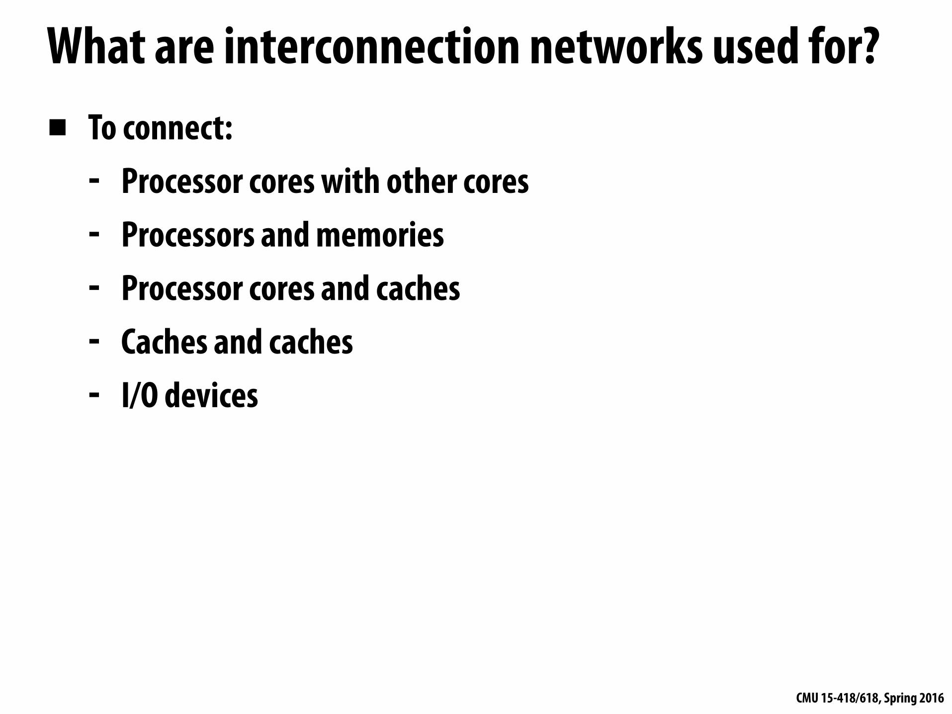
What are interconnection networks used for?▪ To connect:
- Processor cores with other cores - Processors and memories - Processor cores and caches - Caches and caches - I/O devices
CMU 15-418/618, Spring 2016
Why is the design of the interconnection network important?▪ System scalability
- How large of a system can be built? - How easy is it to add more nodes (e.g., cores)
▪ System performance and energy efficiency - How fast can cores, caches, memory communicate - How long is latency to memory? - How much energy is spent on communication?
CMU 15-418/618, Spring 2016
With increasing core counts…
Tilera GX 64-core chip
Intel Xeon Phi (72-core x86)
Intel core i7 (4-CPU cores, + GPU)
Scalability of on-chip interconnection network becomes increasingly important
Tegra K1: 4 + 1 ARM cores + GPU cores
CMU 15-418/618, Spring 2016
Interconnect terminology
CMU 15-418/618, Spring 2016
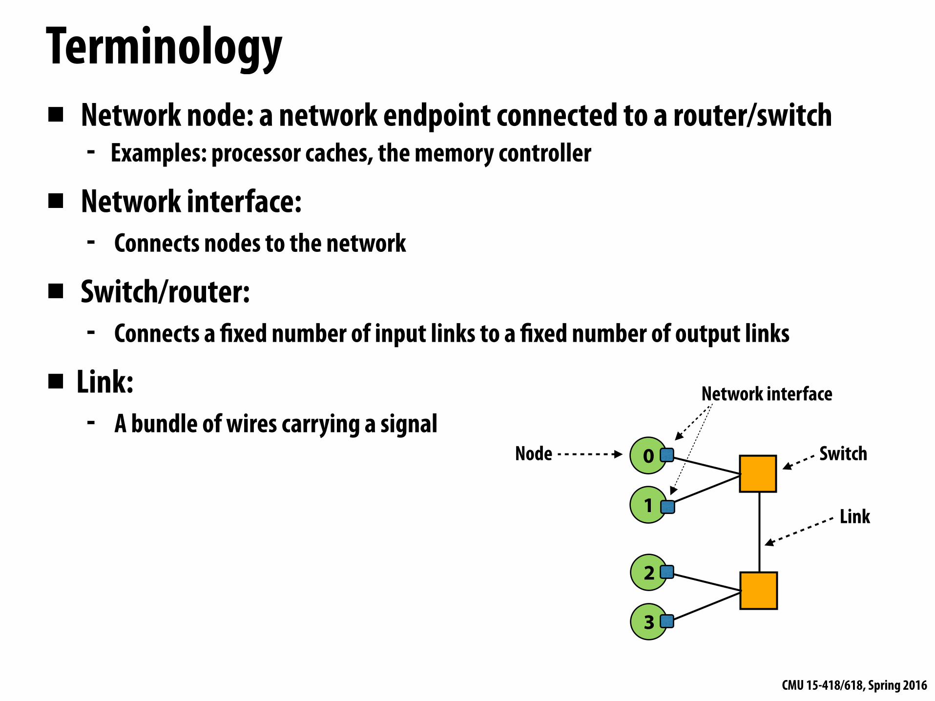
Terminology▪ Network node: a network endpoint connected to a router/switch
- Examples: processor caches, the memory controller
▪ Network interface: - Connects nodes to the network
▪ Switch/router: - Connects a fixed number of input links to a fixed number of output links
▪ Link: - A bundle of wires carrying a signal
0
1
2
3
Node
Link
Switch
Network interface
CMU 15-418/618, Spring 2016
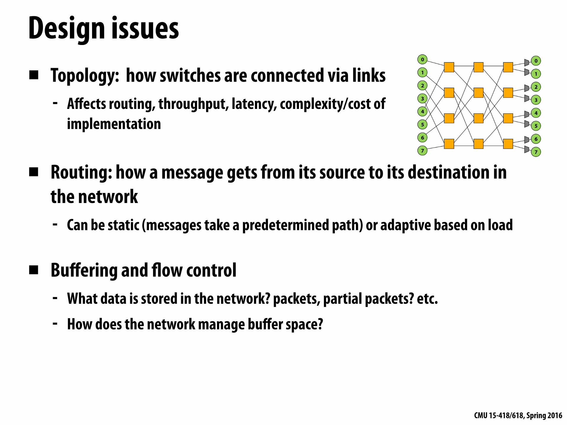
Design issues▪ Topology: how switches are connected via links
- Affects routing, throughput, latency, complexity/cost of implementation
▪ Routing: how a message gets from its source to its destination in the network - Can be static (messages take a predetermined path) or adaptive based on load
▪ Buffering and flow control - What data is stored in the network? packets, partial packets? etc. - How does the network manage buffer space?
CMU 15-418/618, Spring 2016
Properties of interconnect topology▪ Routing distance
- Number of links (“hops”) along a route between two nodes
▪ Diameter: the maximum routing distance
▪ Average distance: average routing distance over all valid routes
Example: diameter = 6
CMU 15-418/618, Spring 2016
Properties of interconnect topology▪ Direct vs. indirect networks
- Direct network: endpoints sit “inside” the network - e.g., mesh is direct network: every node is both an endpoint and a switch
Direct network Indirect network
CMU 15-418/618, Spring 2016
Properties of an interconnect topology▪ Bisection bandwidth:
- Common metric of performance for recursive topologies - Cut network in half, sum bandwidth of all severed links - Warning: can be misleading as it does not account for switch and routing efficiencies
▪ Blocking vs. non-blocking: - If connecting any pairing of nodes is possible, network is non-blocking (otherwise,
it’s blocking)
CMU 15-418/618, Spring 2016
Example: blocking vs. non-blocking▪ Is this network blocking or non-blocking?
0
1
2
3
4
5
6
7
0
1
2
3
4
5
6
7
Conflict
- Consider simultaneous messages from 0-to-1 and 3-to-7. - Consider simultaneous messages from 1-to-6 and 3-to-7. Blocking!!!
Note: in this network illustration, each node is drawn twice for clarity (at left and at right)
CMU 15-418/618, Spring 2016
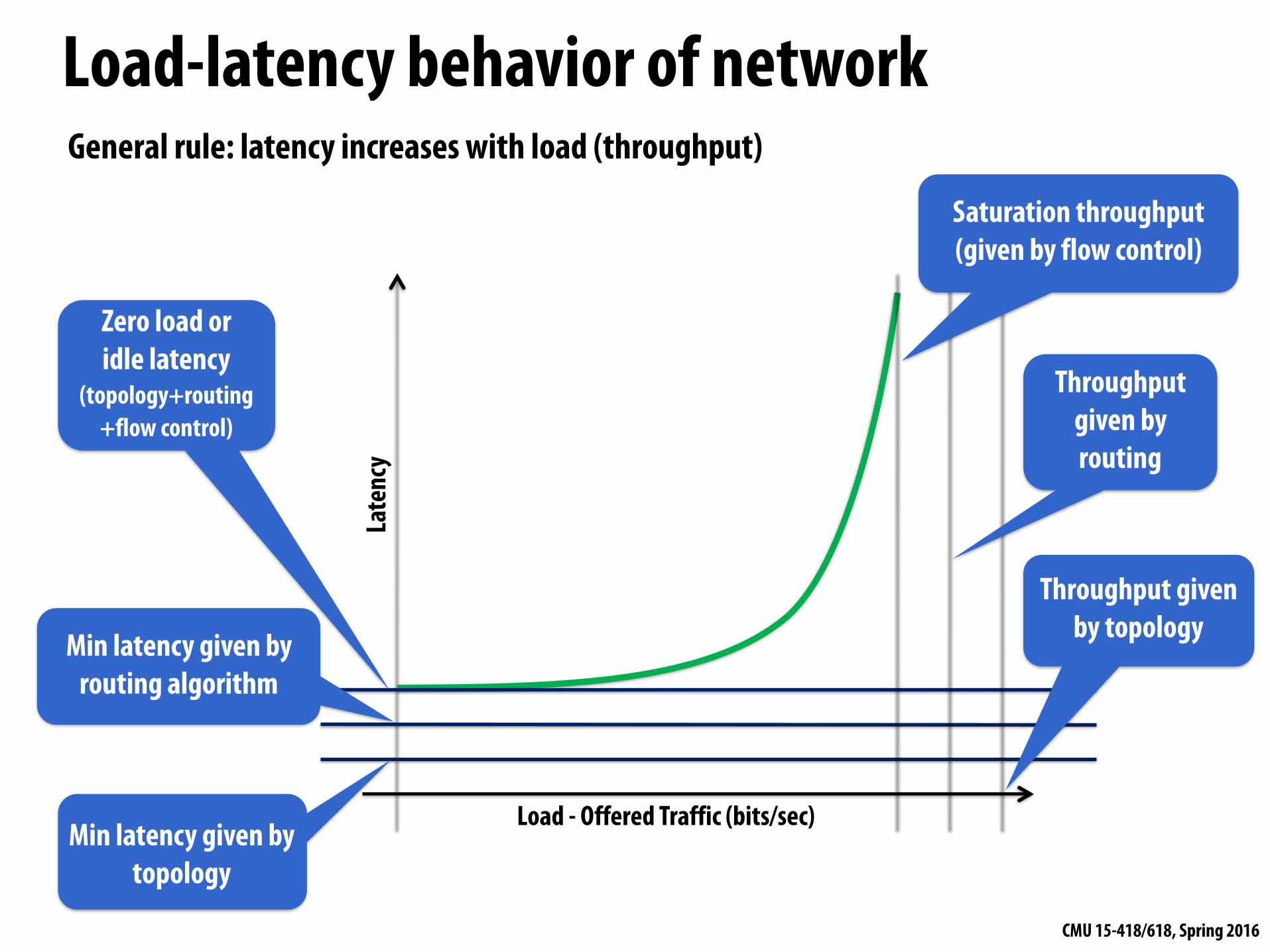
Late
ncy
Load - Offered Traffic (bits/sec)Min latency given by
topology
Min latency given by routing algorithm
Zero load or idle latency
(topology+routing+flow control)
Throughput given by topology
Throughput given by routing
Saturation throughput (given by flow control)
Load-latency behavior of networkGeneral rule: latency increases with load (throughput)
CMU 15-418/618, Spring 2016
Interconnect topologies
CMU 15-418/618, Spring 2016
Many possible network topologiesBus Crossbar Ring Tree Omega Hypercube Mesh Torus Butterfly …
CMU 15-418/618, Spring 2016
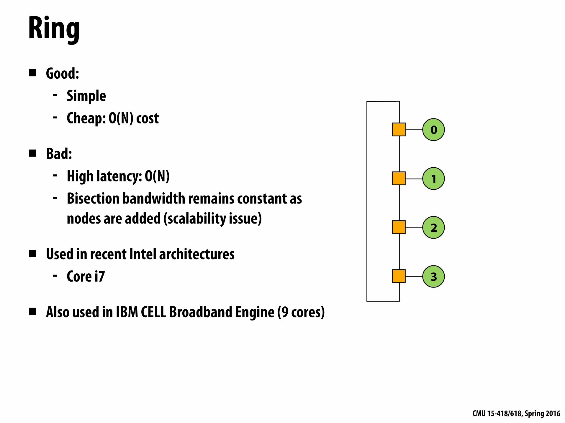
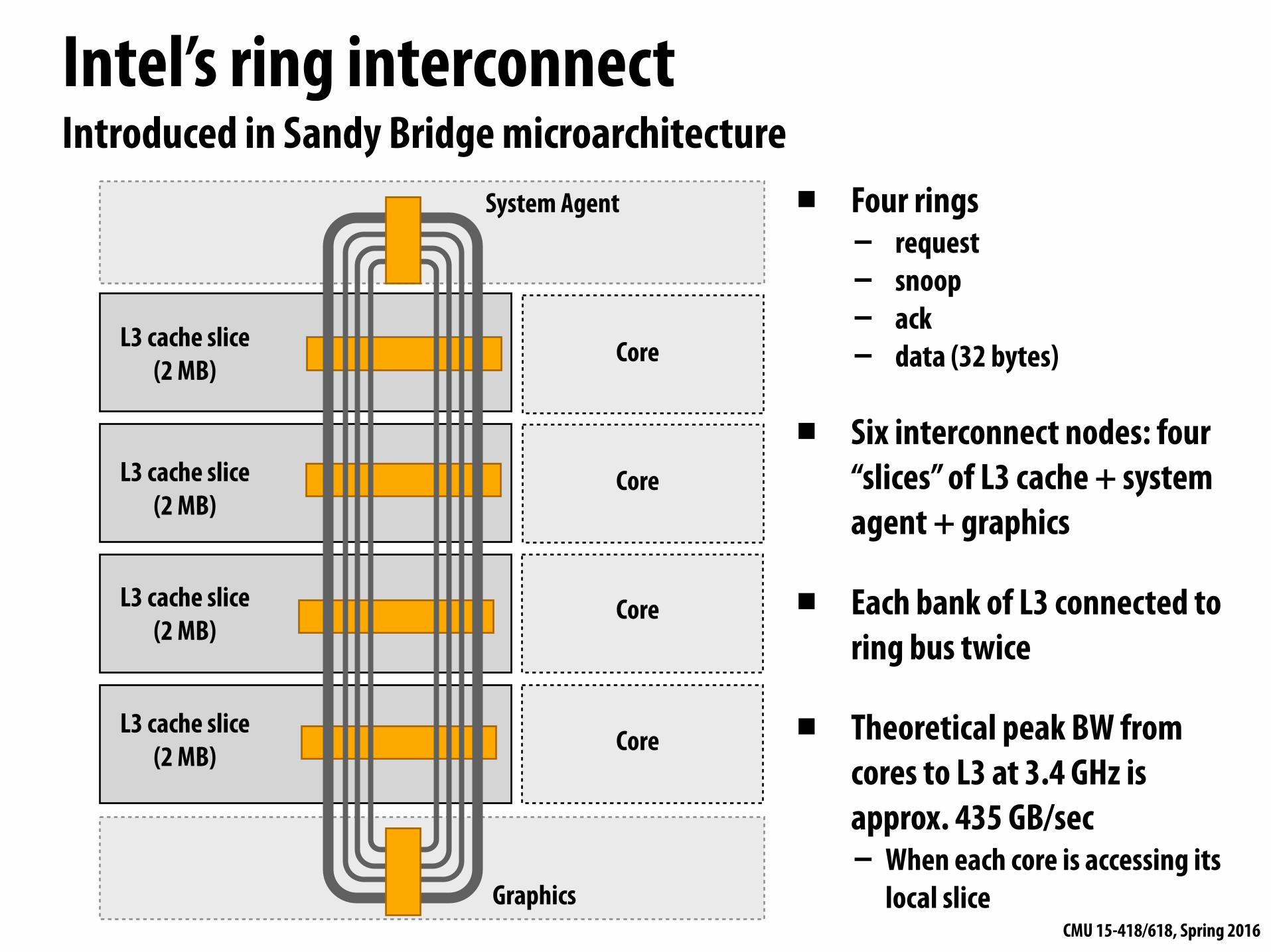
Bus interconnect▪ Good:
- Simple design - Cost effective for a small number of nodes - Easy to implement coherence (via snooping)
▪ Bad: - Contention: all nodes contend for shared bus - Limited bandwidth: all nodes communicate over same wires (one
communication at a time) - High electrical load = low frequency, high power
0 1 2 3 4
CMU 15-418/618, Spring 2016
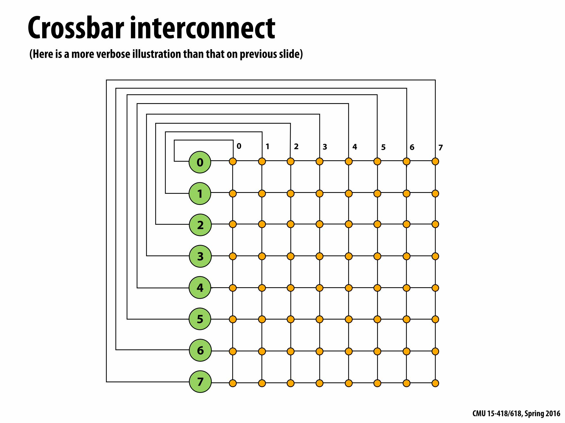
Crossbar interconnect▪ Every node is connected to every
other node (non-blocking, indirect)
▪ Good: - O(1) latency and high bandwidth
▪ Bad: - Not scalable: O(N2) switches - High cost - Difficult to arbitrate at scale
0
1
2
3
4
5
6
7
0 1 2 3 4 5 6 7
Note: in this network illustration, each node is drawn twice for clarity (at left and at top)
8-node crossbar network (N=8)
Crossbar scheduling algorithms / efficient hardware implementations are still active research areas.
CMU 15-418/618, Spring 2016
Crossbar interconnect
0
1
2
3
4
5
6
7
0 1 2 3 4 5 6 7
(Here is a more verbose illustration than that on previous slide)
CMU 15-418/618, Spring 2016
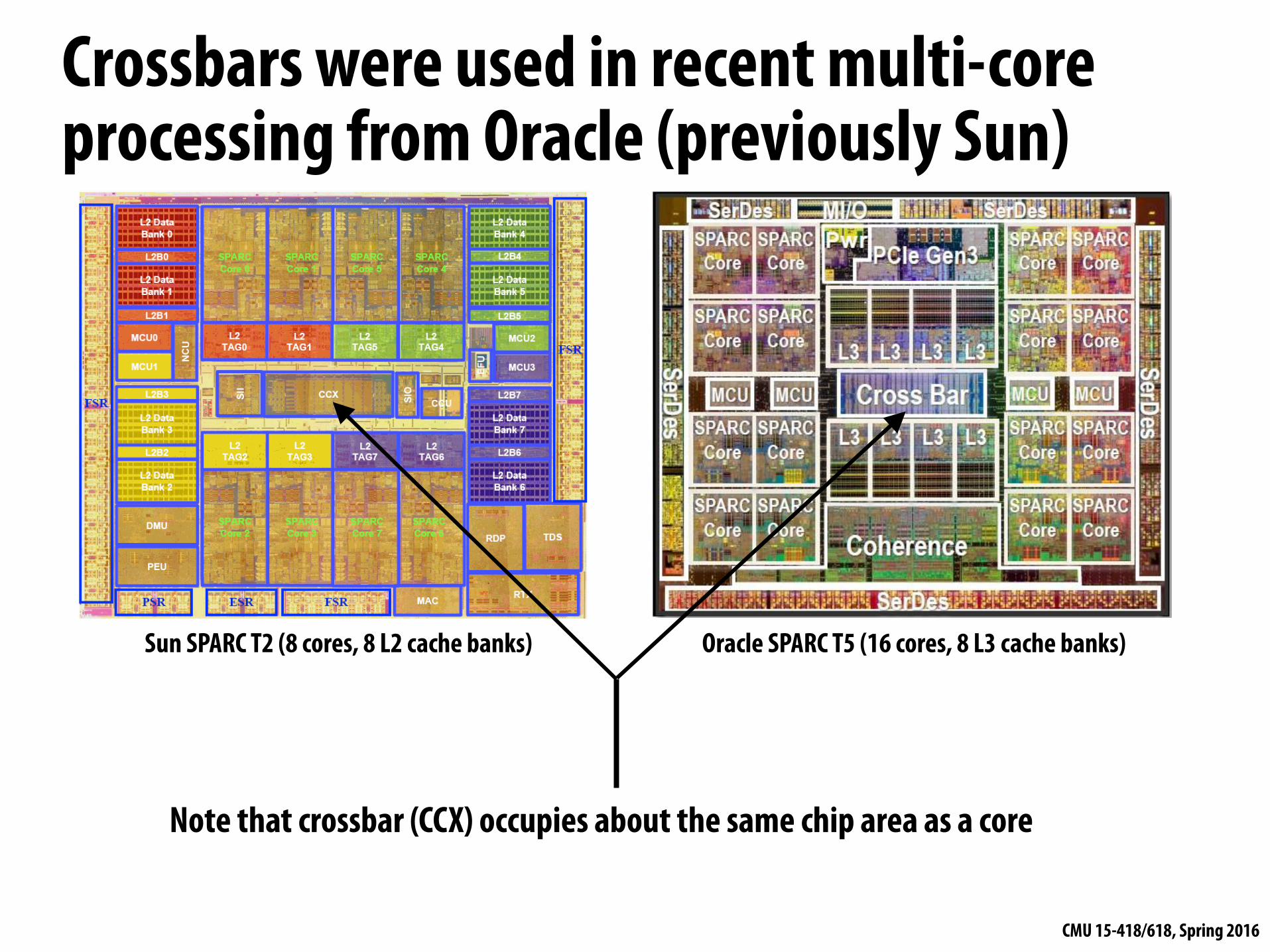
Crossbars were used in recent multi-core processing from Oracle (previously Sun)
Note that crossbar (CCX) occupies about the same chip area as a core
Three Cluster Modes (1) All-to-All (2) Quadrant (3) Sub-NUMA Clustering
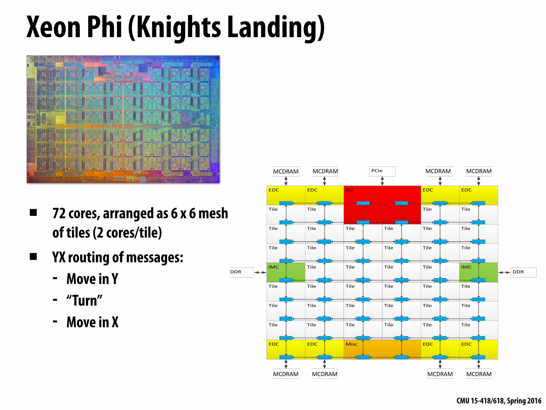
Misc
IIOEDC EDC
Tile Tile
Tile Tile Tile
EDC EDC
Tile Tile
Tile Tile Tile
Tile Tile Tile Tile Tile Tile
Tile Tile Tile Tile Tile Tile
Tile Tile Tile Tile Tile Tile
Tile Tile Tile Tile Tile Tile
EDC EDC EDC EDC
iMC Tile Tile Tile Tile iMC
OPIO OPIO OPIO OPIO
OPIO OPIO OPIO OPIO
PCIe
DDR DDR
MCDRAM MCDRAM MCDRAM MCDRAM
MCDRAM MCDRAM MCDRAM MCDRAM
Xeon Phi (Knights Landing)
▪ 72 cores, arranged as 6 x 6 mesh of tiles (2 cores/tile)
▪ YX routing of messages: - Move in Y - “Turn” - Move in X
CMU 15-418/618, Spring 2016
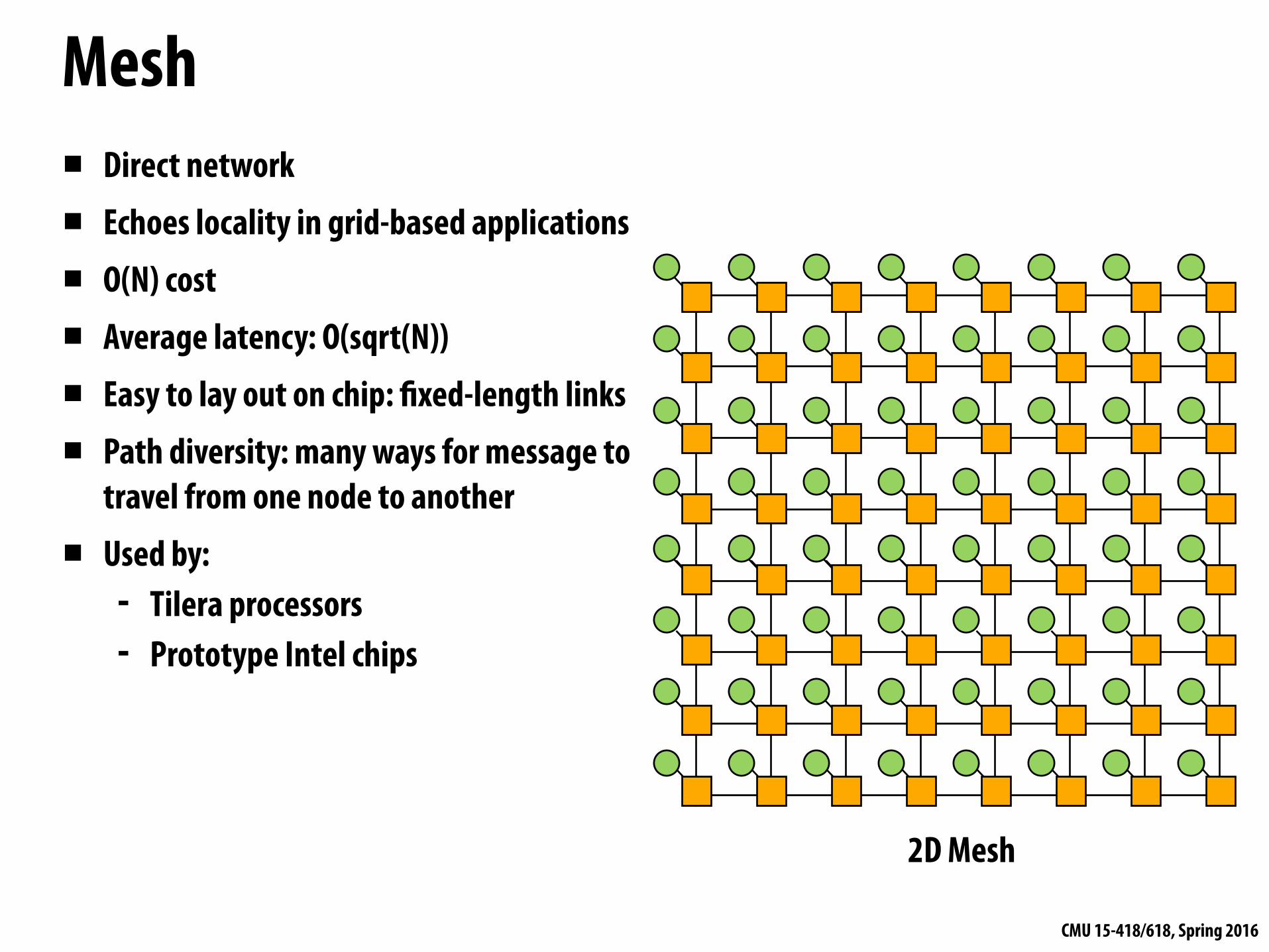
Torus▪ Characteristics of mesh topology are different
based on whether node is near edge or middle of network (torus topology introduces new links to avoid this problem)
▪ Still O(N) cost, but higher cost than 2D grid
▪ Higher path diversity and bisection BW than mesh
▪ Higher complexity - Difficult to layout on chip - Unequal link lengths
2D Torus
CMU 15-418/618, Spring 2016
Trees▪ Planar, hierarchical topology
▪ Like mesh/torus, good when traffic has locality
▪ Latency: O(lg N)
▪ Use “fat trees” to alleviate root bandwidth problem (higher bandwidth links near root)
0 1 2 3 4 5 6 7
Fat TreeH-Tree
0
1
2
3
4
5
6
7
8
9
10
11
12
13
14
15
CMU 15-418/618, Spring 2016
Hypercube▪ Low latency: O(lg N)
▪ Radix: O(lg N)
▪ Number of links O(N lg N)
▪ 6D hypercube used in 64-core Cosmic Cube computer developed at Caltech in the 80s
▪ SGI Origin used a hypercube0000
0101
0100
0001 0011
0010
0110
0111
1000
1101
1100
1001 1011
1010
1110
1111
CMU 15-418/618, Spring 2016
Multi-stage logarithmic▪ Indirect network with multiple switches between terminals
▪ Cost: O(N lg N)
▪ Latency: O(lg N)
▪ Many variations: Omega, butterfly, Clos networks, etc…
0
1
2
3
4
5
6
7
000
001
010
011
100
101
110
111
0
1
2
3
4
5
6
7
000
001
010
011
100
101
110
111Omega Network
CMU 15-418/618, Spring 2016
Review: network topologies
Topology
Direct/Indirect
Blocking/ Non-blocking
Cost
Latency
Crossbar
Indirect
Non-blocking
O(N2)
O(1)
Multi-stage log.
Indirect
Blocking (one discussed in class
is, others are not)
O(N lg N)
O(lg N)
Mesh
Direct
Blocking
O(N)
O(sqrt(N)) (average)
CMU 15-418/618, Spring 2016
Buffering and flow control
CMU 15-418/618, Spring 2016
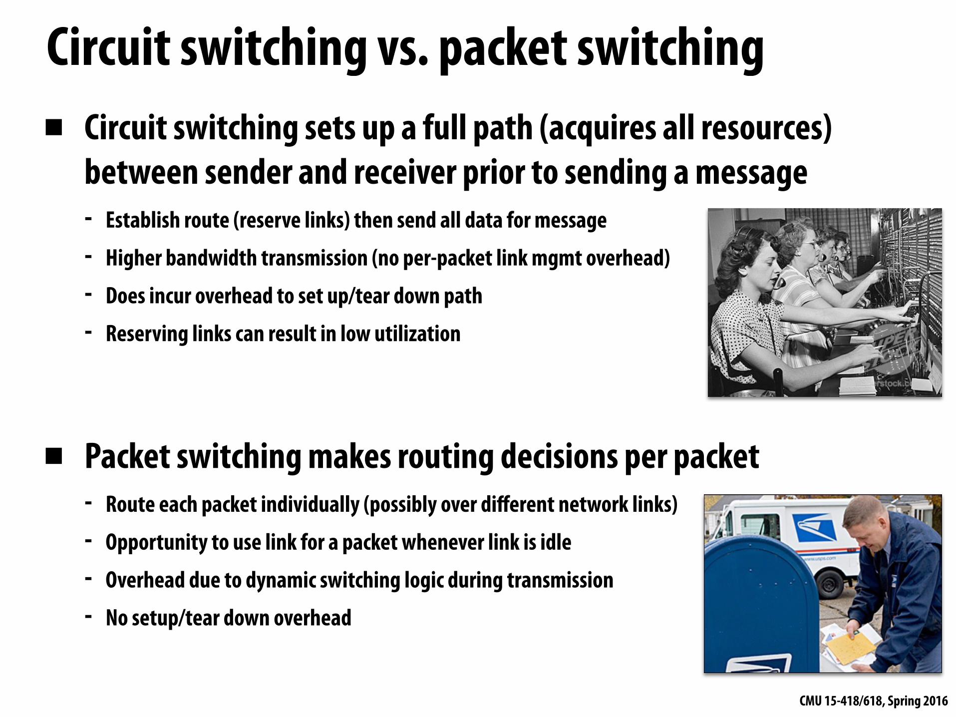
Circuit switching vs. packet switching▪ Circuit switching sets up a full path (acquires all resources)
between sender and receiver prior to sending a message - Establish route (reserve links) then send all data for message - Higher bandwidth transmission (no per-packet link mgmt overhead) - Does incur overhead to set up/tear down path - Reserving links can result in low utilization
▪ Packet switching makes routing decisions per packet - Route each packet individually (possibly over different network links) - Opportunity to use link for a packet whenever link is idle - Overhead due to dynamic switching logic during transmission - No setup/tear down overhead
CMU 15-418/618, Spring 2016
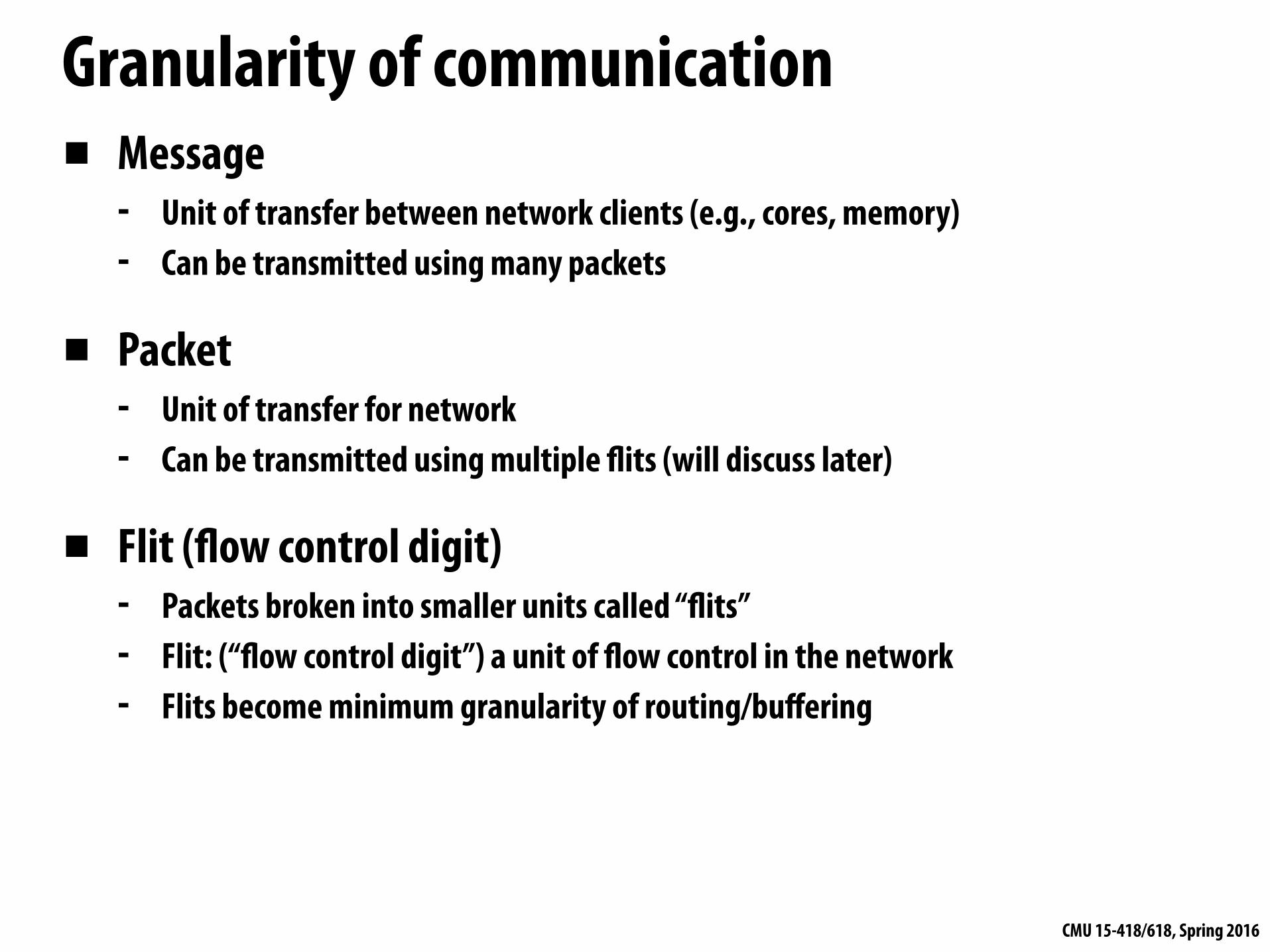
Granularity of communication▪ Message
- Unit of transfer between network clients (e.g., cores, memory) - Can be transmitted using many packets
▪ Packet - Unit of transfer for network - Can be transmitted using multiple flits (will discuss later)
▪ Flit (flow control digit) - Packets broken into smaller units called “flits” - Flit: (“flow control digit”) a unit of flow control in the network - Flits become minimum granularity of routing/buffering
CMU 15-418/618, Spring 2016
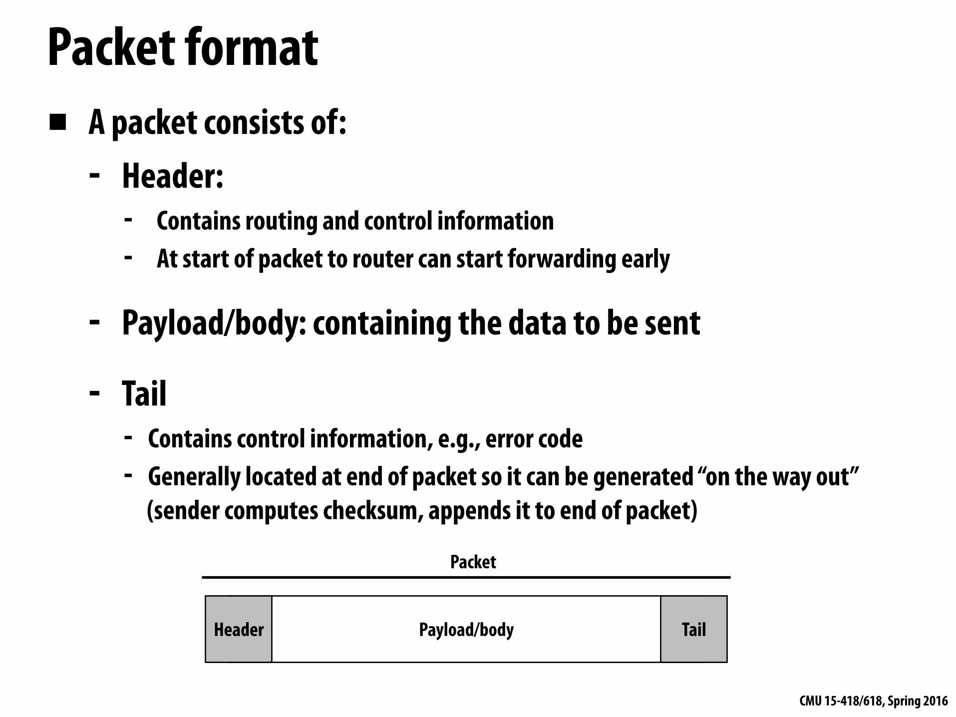
Packet format▪ A packet consists of:
- Header: - Contains routing and control information - At start of packet to router can start forwarding early
- Payload/body: containing the data to be sent
- Tail - Contains control information, e.g., error code - Generally located at end of packet so it can be generated “on the way out”
(sender computes checksum, appends it to end of packet)
Header TailPayload/body
Packet
CMU 15-418/618, Spring 2016
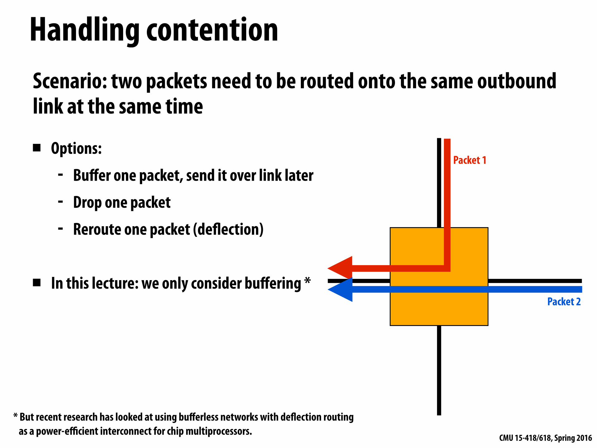
Handling contention
Packet 1
Packet 2
Scenario: two packets need to be routed onto the same outbound link at the same time
▪ Options: - Buffer one packet, send it over link later - Drop one packet - Reroute one packet (deflection)
▪ In this lecture: we only consider buffering *
* But recent research has looked at using bufferless networks with deflection routing as a power-efficient interconnect for chip multiprocessors.
CMU 15-418/618, Spring 2016
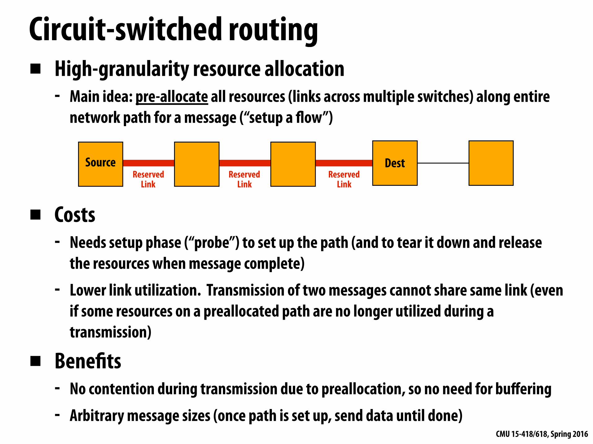
▪ High-granularity resource allocation - Main idea: pre-allocate all resources (links across multiple switches) along entire
network path for a message (“setup a flow”)
▪ Costs - Needs setup phase (“probe”) to set up the path (and to tear it down and release
the resources when message complete) - Lower link utilization. Transmission of two messages cannot share same link (even
if some resources on a preallocated path are no longer utilized during a transmission)
▪ Benefits - No contention during transmission due to preallocation, so no need for buffering - Arbitrary message sizes (once path is set up, send data until done)
Circuit-switched routing
DestSourceReserved
LinkReserved
LinkReserved
Link
CMU 15-418/618, Spring 2016
Store-and-forward (packet-based routing)▪ Packet copied entirely into network switch before moving to next node
▪ Flow control unit is an entire packet - Different packets from the same message can take different routes, but all data in a packet is
transmitted over the same route
▪ Requires buffering for entire packet in each router
Source
Destination
One packet Packet Buffer Packet BufferPacket Buffer
Packet Buffer Packet Buffer Packet Buffer
Busy Link Busy Link
Busy Link
Note to students: in lecture this slide was animated and the final build shown here is not illustrative of store-and-forward routing concept (please refer to lecture video)
▪ High per-packet latency (latency = packet transmission time on link x network distance)
CMU 15-418/618, Spring 2016
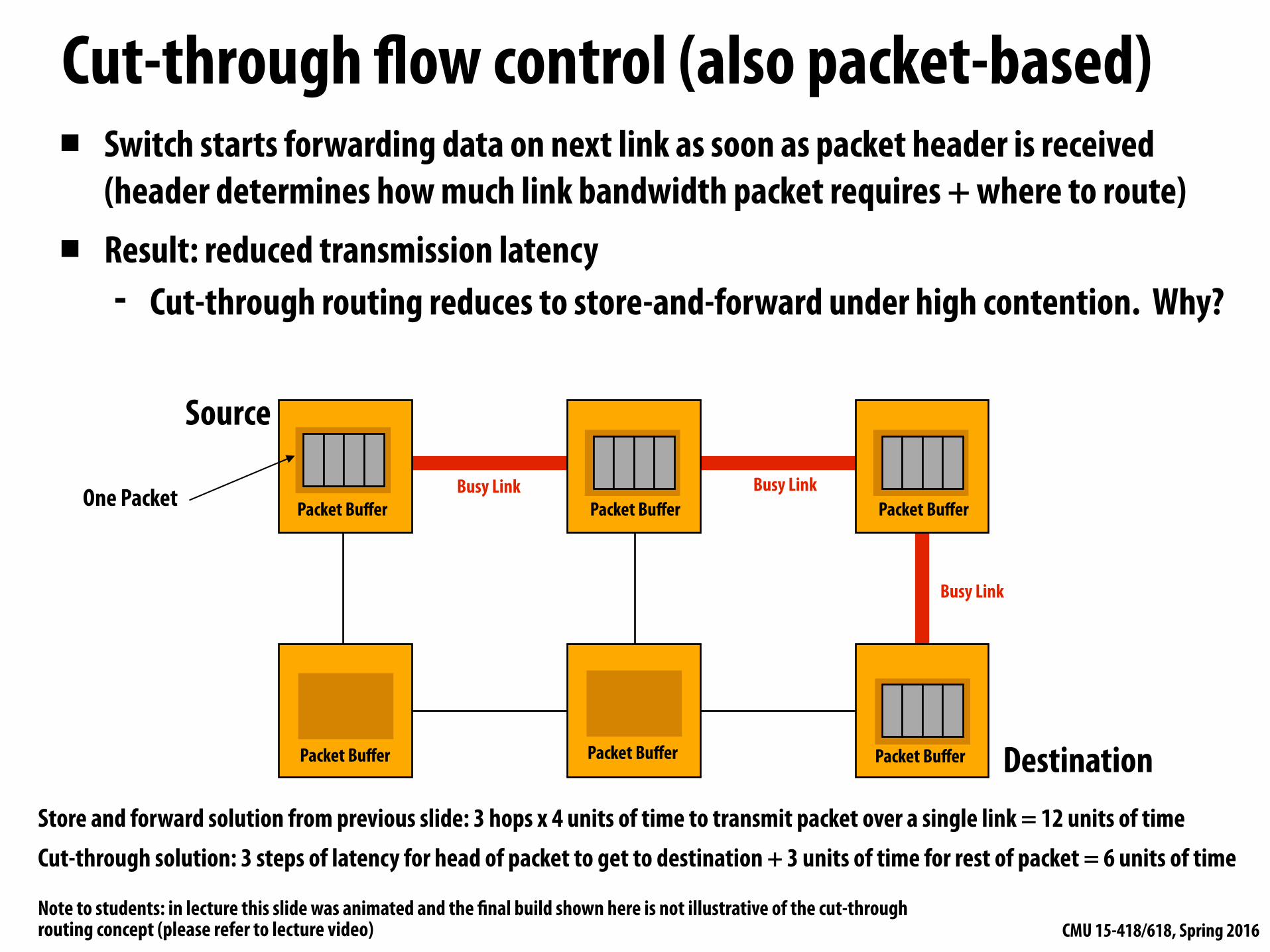
Cut-through flow control (also packet-based)▪ Switch starts forwarding data on next link as soon as packet header is received
(header determines how much link bandwidth packet requires + where to route) ▪ Result: reduced transmission latency
- Cut-through routing reduces to store-and-forward under high contention. Why?
Source
Destination
One Packet Packet Buffer Packet BufferPacket Buffer
Packet Buffer Packet Buffer Packet Buffer
Busy Link Busy Link
Busy Link
Store and forward solution from previous slide: 3 hops x 4 units of time to transmit packet over a single link = 12 units of time Cut-through solution: 3 steps of latency for head of packet to get to destination + 3 units of time for rest of packet = 6 units of time
Note to students: in lecture this slide was animated and the final build shown here is not illustrative of the cut-through routing concept (please refer to lecture video)
CMU 15-418/618, Spring 2016
Cut-through flow control▪ If output link is blocked (cannot transmit head), transmission
of tail can continue - Worst case: entire message is absorbed into a buffer in a switch (cut-through flow
control degenerates to store-and-forward in this case) - Requires switches to have buffering for entire packet, just like store-and-forward
CMU 15-418/618, Spring 2016
Wormhole flow control▪ Flit (flow control digit)
- Packets broken into smaller units called “flits” - Flit: (“flow control digit”) a unit of flow control in the network - Flits become minimum granularity of routing/buffering
- Recall: up until now, packets were the granularity of transfer AND flow control and buffering (store-and-forward, cut-through routing)
Head Flit
Tail FlitFlit Flit Flit Flit Flit Flit
Packet
Head Flit
Tail FlitFlit Flit Flit Flit Flit Flit
Packet
Message
CMU 15-418/618, Spring 2016
Wormhole flow control▪ Routing information only in head flit ▪ Body flits follows head, tail flit flows body ▪ If head flit blocks, rest of packet stops ▪ Completely pipelined transmission
- For long messages, latency is almost entirely independent of network distance. Why?
Source
Destination
Flit Buffer Flit BufferFlit Buffer
Flit Buffer Flit Buffer Flit Buffer
Busy Link Busy Link
Busy Link
Head flit
Tail flit
Body flits (2 in this example)
Example: Four-flit packet sent using wormhole flow control
HT B0B1
B1 B0
H
T
CMU 15-418/618, Spring 2016
Problem: head-of-line blocking
Flit Buffer Flit BufferFlit Buffer
Flit Buffer Flit Buffer Flit Buffer
Idle link (reserved)
Idle link (reserved)
Idle link (reserved)
Head flit for gray packet: (blocked waiting for this
busy link)
Flit Buffer Flit BufferFlit Buffer
Head flit for blue packet:(route is free, but blocked
behind gray packet in buffer)
Blue flits to be routed this way to their dest
(this link is free)
CMU 15-418/618, Spring 2016
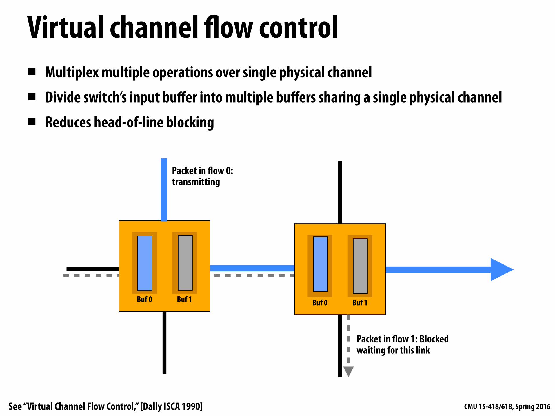
Virtual channel flow control▪ Multiplex multiple operations over single physical channel
▪ Divide switch’s input buffer into multiple buffers sharing a single physical channel
▪ Reduces head-of-line blocking
Buf 0 Buf 1Buf 0 Buf 1
Packet in flow 0: transmitting
Packet in flow 1: Blocked waiting for this link
See “Virtual Channel Flow Control,” [Dally ISCA 1990]
CMU 15-418/618, Spring 2016
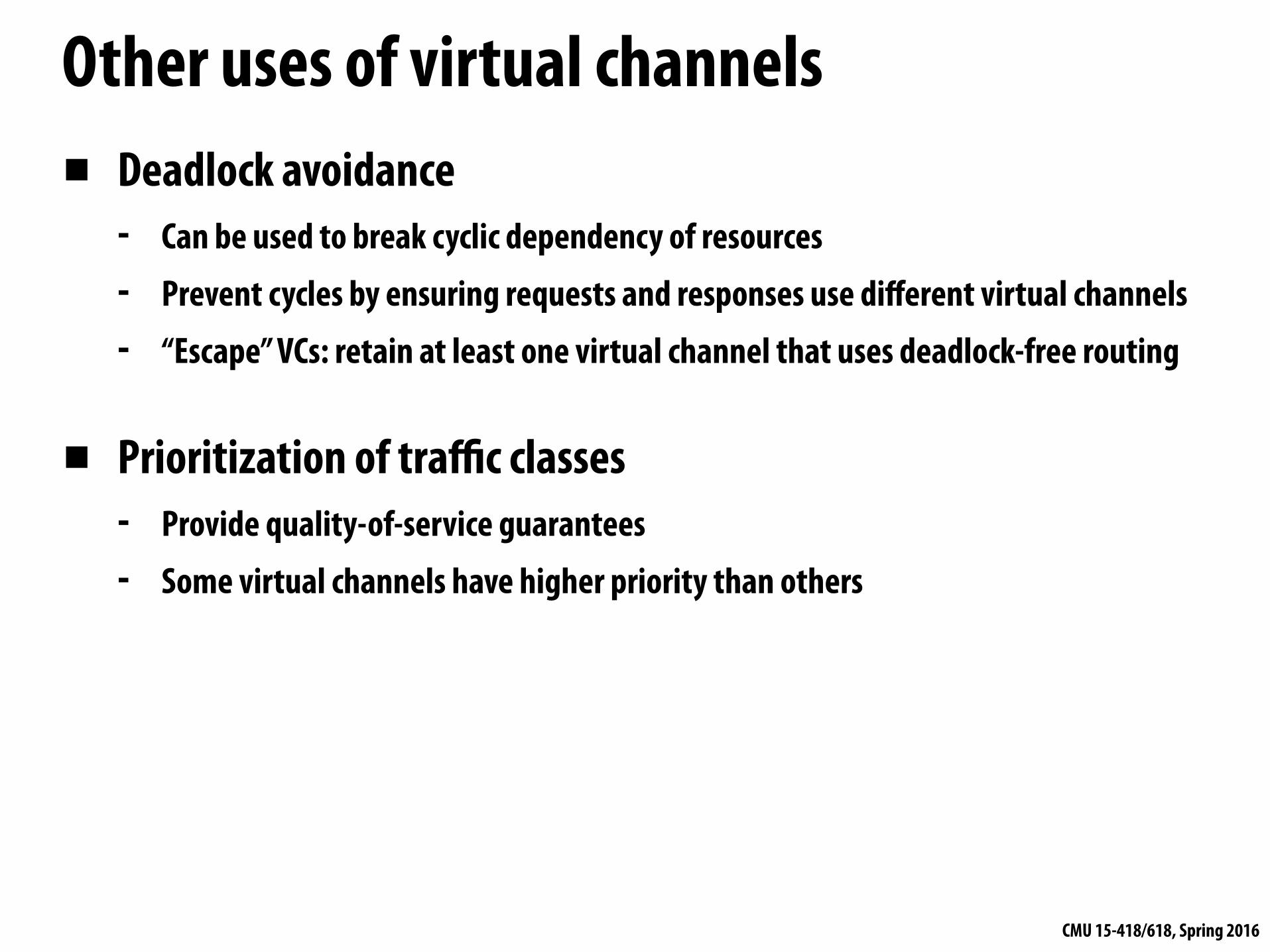
Other uses of virtual channels▪ Deadlock avoidance
- Can be used to break cyclic dependency of resources - Prevent cycles by ensuring requests and responses use different virtual channels - “Escape” VCs: retain at least one virtual channel that uses deadlock-free routing
▪ Prioritization of traffic classes - Provide quality-of-service guarantees - Some virtual channels have higher priority than others
CMU 15-418/618, Spring 2016
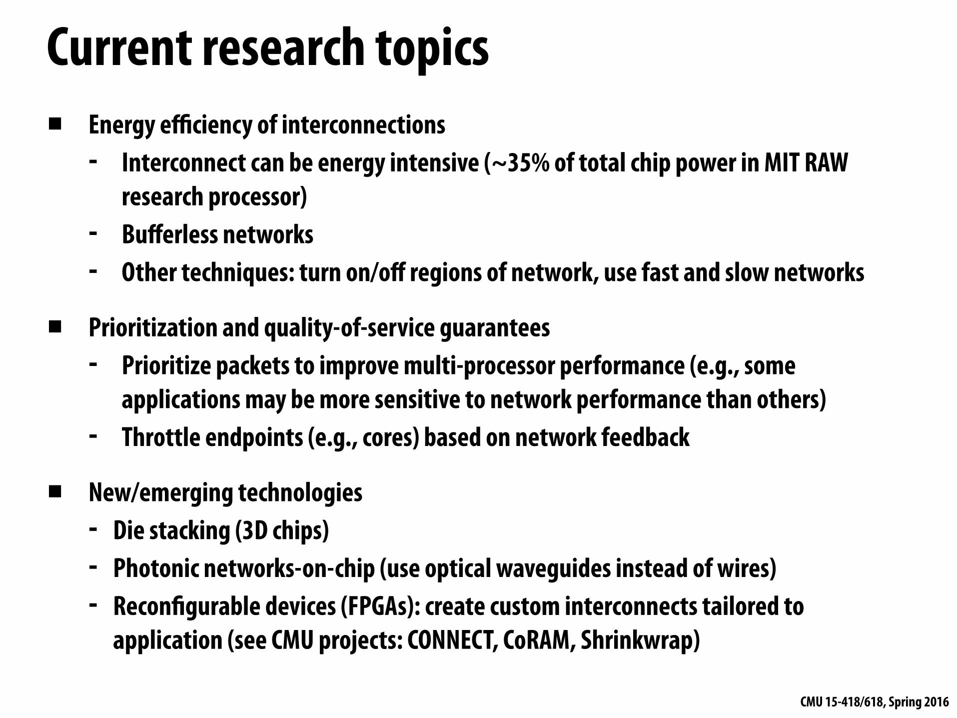
Current research topics▪ Energy efficiency of interconnections
- Interconnect can be energy intensive (~35% of total chip power in MIT RAW research processor)
- Bufferless networks - Other techniques: turn on/off regions of network, use fast and slow networks
▪ Prioritization and quality-of-service guarantees - Prioritize packets to improve multi-processor performance (e.g., some
applications may be more sensitive to network performance than others) - Throttle endpoints (e.g., cores) based on network feedback
▪ New/emerging technologies - Die stacking (3D chips) - Photonic networks-on-chip (use optical waveguides instead of wires) - Reconfigurable devices (FPGAs): create custom interconnects tailored to
application (see CMU projects: CONNECT, CoRAM, Shrinkwrap)
CMU 15-418/618, Spring 2016
Summary▪ The performance of the interconnection network in a modern multi-processor is
critical to overall system performance - Buses do not scale to many nodes - Historically interconnect was off-chip network connecting sockets, boards, racks - Today, all these issues apply to the design of on-chip networks
▪ Challenge: efficiently routing data through network - Interconnect is a precious resource (communication is expensive!) - Flit-based flow control: fine-grained flow control to make good use of available
link bandwidth - If interested, much more to learn about (not discussed in this class): ensuring
quality-of-service, prioritization, reliability, deadlock, livelock, etc.