75
Lecture # 16 Dr. Dave Whittum May 29,1998
Lecture 16
Dr Dave Whittum
May 291998
Accelerator
1 High-Gra deration amp You
3 Proof-of-Princtpte Experiments
httplww slacstanford edugrparb
Year
Gradient amp
102
e 101
r h 100 1 J
T-----7- __ --------I _I- I
eter wave rn ic row we
plasma -
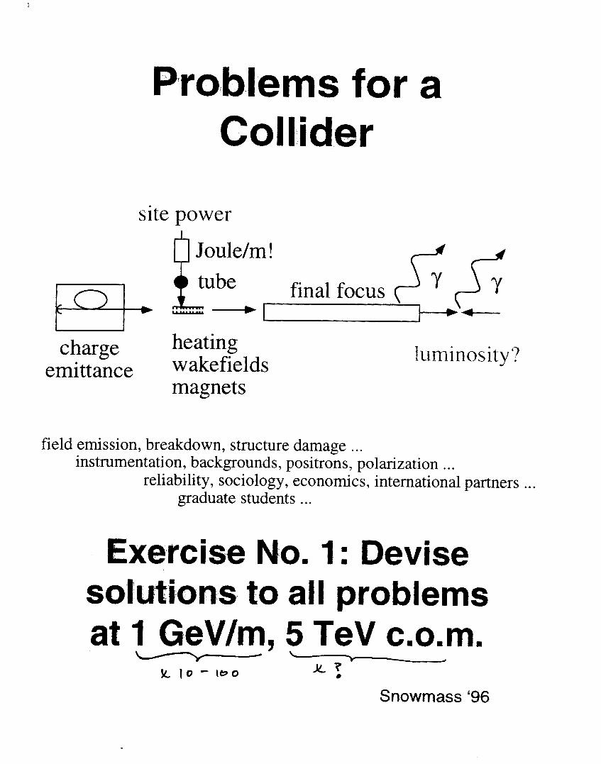
Problems for a Collider
site power
luminosity charge heating
emittance w akefields magnets
field emission breakdown structure damage instrumentation backgrounds positrons polarization
reliability sociology economics international partners graduate students
Exercise No 1 Devise solutions to all problems at 1 GeVm 5 TeV c0m
IC 7- d
0 )c 10 - le0
Snowmass lsquo96
- --- r - - _ ^ ~ _
Pd- 7
ro
P 3 eurok
N 1 a- P
- - e 7
I
J
Q) k g
I
gt
il
i
C -
c )- c u i ac PI
m
Q
L
I$
8 d
Lr d s 4 a 1
Y I U Y
k 4
i i
i I
_
7
Lw FA
Shgm-yof n Laser Wakefield Reseam4 R a d amp ~ ~~~~ ~
0 Wa kefield acceleration of M e V electrons
field gradient - 2 GeVcm
transverse emittance 1 mm-mrad
electron bunch-density gt log (05 nC) energy spread 100 acceleration onset a t 3Pc 2 and G n 10 trapping of sidescatter-heated electrons (gt 500 ke
Nonlinear optics wi th relativistic plasmas
wa kefield onset at Pc2 =gt relativistic self-focusing
relativistic self- phase modulation
possible evidence for electron cavitation
eamp Resonant Laser Plasma Accelerator (RLPA) optimized laser pulse t ra in
improved power efficiency (gt factor of 10)
o Laser Injected Laser Accelerator (LILAC) all-optical synchronized injection and acceleration T~ = 10 fs low emittance low energy-spread
i i i
I
i
i
I
I 1
I J I rn
heat pipes and producing and diagnosing lithium plasma using photoionization and
spectroscopyllnterferometry respectively After surveying the literature we have designed such
a source for our present application
Figure 22 Schematic layout of the proposed lithium plasma source and its connection to the FFIB beamline
Figure 22 shows the schematic of the lithium plasma source The first thing to note is
that it is a completely sealed system with a few micron thick diamond windowss on either end
Diamond was chosen because of its strength ability to handle thermal stress high conductivity and-ability to transmit the 6 eV photons that are needed to photoionize the lithium vaporm The
second thing to note is that upstream of the source is a lL2 meter ion tube with its own turbo-
molecular vacuum system and a fast feedback controlled vacuum valve that will isolate the FFIB beam line should the diamond window fail In a lithium oven the lithium vapor is
confined in the heated region by a buffer gas which in this case will be helium Since the
lithium can only exist as high pressure vapor in the heated region pressure balance requires helium to move away into the colder region of the source Thus there is a boundary region
where transition from mainly lithium (on the hot side) to mainly helium (on the cold side)
36
lM
or
E-157 --
A Pfoposal to the Stanford Linear Accelerator Center
R Assnnann 1
Pmwy Investigators
Joshi T KououlrPc W tremans R ltmann
It Asswmnn P Chtn FJ Decker R herson P Raimondi T R a d d u i m e r S Rokni R H Sitmonn D Wal t D Whinum SLAC
C Clayon C Joshi K Marsh W M o i G Wmg UCLA
T Kairoulear S kc USC
April 1997
Abstract A plasma-hxd wakefield acceleration (PWFA) experiment is proposed that will accelerate paru of an SLC bunch by up to 1 GeVm over a kngth of 1 m A singk SLC bunch is used to both induce wakefields in rhe one meter long plasma and to witness the nsulting beam rccclerAon Ihe proposed experiment will explore and further develop the techniques that are Deeded to apply high-gradient plasma wakefield acceleration to large scale accelenton The one meter length of the experiment is about two orders of magnitude larger than other high gradient PWFA experiments and the 1 Vm accelerating gradient is roughly (Ln times larger than that achieved with conventional metallic structures Using existing SLAC facilities the proposed experiment will allow the study of high gradient acceleration at the forefront of advanced accelerator research
3397
Figure 16 Layout of the Final FOCUS Test Beam (FFTB) area for the proposed plasma-wakefield acceierat ion experiment
24
1
3397
0
E 5 Y
E U
s - m
8000
7000
6Ooo
5ooo
oooo 3000
2000 lo00
0
0 2e+14 amp+I4 amp+I4 amp+I4 le+lS 1 2 ~
X- y ------- -
- - -
3
1 I I I I 1 I I
0 5 10 15 20 25 ) 35
15
Figure 24 Calculated horizontal and venical spot sizes at IP-2 for a 1 ps slice with 03 relative energy spread The beam size is plotted as a function of plasma density
It is seen from Figure 24 that the spot sizes with and without the plasma cell are almost
identical for certain plasma densities The ldquotransparencyrdquo condition for the plasma cell was discussed earlier For minimum mismatch effects we expect a spot size for a single 1 ps slice of
better than 1 mm This is comparable to the spot size of the whole bunch The vertical deflection
Ay due to an acceleration of I GeV is
AiE Ay = D- = 33mm E
which is more than three times the vertical spot size The decelaration of the head will be about
05 GeV The expected dispersive shift of 16 mm is still larger than the spot size Assuming a
minimized beta mismatch of t k plasma cell the energy shifts of both head and tail of the bunch
should be easily observed
c Plasma dhgnostic
To be provided
A 3
2 L
e I
euro =
f
i
p I t I I I I I I
01 02 0
08
0 6
04
02
034
032
-002
i
__L_
W C -004
-006
0 0 5 1 15
lh5
tor
Q) v) 0 E L1 0 cn c (cr
0 0 0 0
amp a E
Q
- a - - - - -
t
1
0 l-4 I
Q)
m 0 E
Cr w 0 0
A a
I I
i
_
I I 2
E 3 I I I I i I
r( 0 rl
0- h
0 rn
0
T
I I I I I I I
B
9
1 I 1
I
I I 1 1 I I I
4 p
l a I I I I I 1
Of 5
- 0 -0 5
3 f
- i
1
05
- 0 5
- 1
-
-
I I I I
2 4 0 6 0 8 0 1 060 0 et z
A
C
P
0
ry rl 0
rl rc
1Oa
1 00
102
i 6
I
I
i
l
E 00
I I I I I I I
08 5 1 0 1 5 2 0 2 5 3 0
I I I I I
- MACRO
1 0 2 0 2 5 3 0 kpz
P
I
1 g f
[- i 1 f 1 f i m i w c a e l 1
E
v
0
wherc the tilde dciotes thl Lapltcc iisiorlll and p is the Laplace
transform variable Invertin thc Lab) c transforill the solution f o r
the beam centroid it
and we have useti G ( p ) = G lp 1 1 1 intcgral niily be c o m p u t e d
approximately by iiie methid of st^ t descents and the r e su l t
for the beam cenrroid disp1rcemcnr I
with exponent
L = 2 6 ~lO-~(gk f ) [ (w r~~~- y ] 2
Comparing this i t 1 Eq ( 5 ) one I-
been replaced with iie len_cli sci~le
more favorable s c ~ i i fig
that the length scale Ap h a s
iind varies IS (Q7 )-2 a much
For illustratiol we cosider a Ii Lrical exaniple corresponding
to a 25 TeV acccirator s i l i t h ioiis exiiiiiple we a s s u m e
17
bb2=05 and h=)bpm However i n iis cic wc assume injection
at a h i g h energy lOGeV (yF2x lo4) lsquoollowcd hy acceleration to
251TeV ( 5 - 5 ~ 10rdquo) The bcitroii piamp AD=(2y)rsquorsquo2i is initially 2 c m
and increases to 3amp1n at tiic csit k)tthcst parameters fixed w e
consider three cises cclti-rcsponclibt t o differcnt accelerating
gradients ( 1 ) 1 Gcrsquolm (2) I OGcrsquoii id (3) 1 OOGcVm Associated -- __c1_
parameters are listctl in Tahlc 1 To camp these scalings we solve EQ
9-
(41) numerically n i i h rcsuli inc l ic ird I I I Fig 3 Thc analytic results
are the dashed cives o Ila~cJ rh f ig 3 and they are almost
indistinguishable 1lsquo1 om the iiumcricI v4sults Eviclcntly only in t h e
lower gradient c a ~ i s the iiistahilit for concCrn
-
Y I
n
+ _ +
+ +
p =024clpamp =OIScm
U = O I J m t =48x1~cm-rabE=o9x1o- cm-~
F_Zimmemrm et 01 M A C
1i
crsquo
-
with
wits
i
1- gttp-+t
I = lp - +tp + +f - s
1 4 x lolo-
c w ~ w k neutralimtim in a plasma at the interaction point of an electron-gositron collidcr it c h q a ~ i j d i A for iha ptripodc of suppressing bcrmsirslrlung Conditions arc derived for good current ndi4r5amp tjy plasma return currents and the resulu of numerical simulations confirming the t amp q we rcpomxj Paramelerr arc presented for a TCV-CI~SS Linear Collidcr (TLC) employing pf-1 cunipcliwion nc problem of beam-plasma background reactions is noted
T~RX Rcginies in thc Plnsnia Compcnration Problcm
Very Early Time (1 tighly Colhionid Regime)
r gtgt r = (Q)rsquo Y-rsquo
Early Timc (hdoderrrtcly Collisional Rcgimc)
Laic Timc (Collisiotilcss Rcgimc)
v r ltlt 1
TABLE 111
Conditions for Good Current Compensation
16
1 J
12
8 2 00 a 7F at6
04
0 3 IO
7
6
5 c (n Q 3 4 - n - 3
1
O
1 I I I
-c
Nmr (ps)
0 0 2 0 4 0 6 0 8
0
8 O
02
35
30 - (
25 5 - N - 20
1 5
05
04 06 08 1 o Tlmr (ps)
0 02 0 4 06 00 10
08
O
06
a t CU a L
0 c
0
01
1 1
Vacuum Ficld I
1 - 2 3 4
rn
F1CItJRE 2 Tlrc riidiid coortlinrrte i s nornrafizcd by U w l w c tllc rildiirl bcam profile is exy ( - I u ) and kpu = 2
Examplc of Ihc ratlial profilc of the shicltlctl magnetic hchl in the collisionlcss regime 2 2
h
10
10
10 10 IO
kJ
10
10
kpa
FIGURE 4 Reduction in peak B field as 1 function of ku for a flat b u m
k z -
P i c
_ _ _ - -
amem orotcctor
-
C I
v) a P
Q) P 0 r
I
1
I W m m Acceleration Gradient
3
I E9 4 I
E
33 0 0 a m II II
m ti u
r h 4 0
1 4
E Igt c3
0 + 4
II II
I a
7
The Reach of High Energy Physics is limited by its instruments
accelerators
Today e245 60-M W klystrons running at 120 Hz to power a Two-Mile Linac producing 4000 Zrsquos per day Two 2200 m being cumm a B-Factory
3 Yeamp Next 6 Bring worked ~xercises Exercise No 1 Devise solutions to all problems at I GeVm 5 TeV c0m Exercise No 2 Devise Proof-of-Principle Experiments

Accelerator
1 High-Gra deration amp You
3 Proof-of-Princtpte Experiments
httplww slacstanford edugrparb
Year
Gradient amp
102
e 101
r h 100 1 J
T-----7- __ --------I _I- I
eter wave rn ic row we
plasma -
Problems for a Collider
site power
luminosity charge heating
emittance w akefields magnets
field emission breakdown structure damage instrumentation backgrounds positrons polarization
reliability sociology economics international partners graduate students
Exercise No 1 Devise solutions to all problems at 1 GeVm 5 TeV c0m
IC 7- d
0 )c 10 - le0
Snowmass lsquo96
- --- r - - _ ^ ~ _
Pd- 7
ro
P 3 eurok
N 1 a- P
- - e 7
I
J
Q) k g
I
gt
il
i
C -
c )- c u i ac PI
m
Q
L
I$
8 d
Lr d s 4 a 1
Y I U Y
k 4
i i
i I
_
7
Lw FA
Shgm-yof n Laser Wakefield Reseam4 R a d amp ~ ~~~~ ~
0 Wa kefield acceleration of M e V electrons
field gradient - 2 GeVcm
transverse emittance 1 mm-mrad
electron bunch-density gt log (05 nC) energy spread 100 acceleration onset a t 3Pc 2 and G n 10 trapping of sidescatter-heated electrons (gt 500 ke
Nonlinear optics wi th relativistic plasmas
wa kefield onset at Pc2 =gt relativistic self-focusing
relativistic self- phase modulation
possible evidence for electron cavitation
eamp Resonant Laser Plasma Accelerator (RLPA) optimized laser pulse t ra in
improved power efficiency (gt factor of 10)
o Laser Injected Laser Accelerator (LILAC) all-optical synchronized injection and acceleration T~ = 10 fs low emittance low energy-spread
i i i
I
i
i
I
I 1
I J I rn
heat pipes and producing and diagnosing lithium plasma using photoionization and
spectroscopyllnterferometry respectively After surveying the literature we have designed such
a source for our present application
Figure 22 Schematic layout of the proposed lithium plasma source and its connection to the FFIB beamline
Figure 22 shows the schematic of the lithium plasma source The first thing to note is
that it is a completely sealed system with a few micron thick diamond windowss on either end
Diamond was chosen because of its strength ability to handle thermal stress high conductivity and-ability to transmit the 6 eV photons that are needed to photoionize the lithium vaporm The
second thing to note is that upstream of the source is a lL2 meter ion tube with its own turbo-
molecular vacuum system and a fast feedback controlled vacuum valve that will isolate the FFIB beam line should the diamond window fail In a lithium oven the lithium vapor is
confined in the heated region by a buffer gas which in this case will be helium Since the
lithium can only exist as high pressure vapor in the heated region pressure balance requires helium to move away into the colder region of the source Thus there is a boundary region
where transition from mainly lithium (on the hot side) to mainly helium (on the cold side)
36
lM
or
E-157 --
A Pfoposal to the Stanford Linear Accelerator Center
R Assnnann 1
Pmwy Investigators
Joshi T KououlrPc W tremans R ltmann
It Asswmnn P Chtn FJ Decker R herson P Raimondi T R a d d u i m e r S Rokni R H Sitmonn D Wal t D Whinum SLAC
C Clayon C Joshi K Marsh W M o i G Wmg UCLA
T Kairoulear S kc USC
April 1997
Abstract A plasma-hxd wakefield acceleration (PWFA) experiment is proposed that will accelerate paru of an SLC bunch by up to 1 GeVm over a kngth of 1 m A singk SLC bunch is used to both induce wakefields in rhe one meter long plasma and to witness the nsulting beam rccclerAon Ihe proposed experiment will explore and further develop the techniques that are Deeded to apply high-gradient plasma wakefield acceleration to large scale accelenton The one meter length of the experiment is about two orders of magnitude larger than other high gradient PWFA experiments and the 1 Vm accelerating gradient is roughly (Ln times larger than that achieved with conventional metallic structures Using existing SLAC facilities the proposed experiment will allow the study of high gradient acceleration at the forefront of advanced accelerator research
3397
Figure 16 Layout of the Final FOCUS Test Beam (FFTB) area for the proposed plasma-wakefield acceierat ion experiment
24
1
3397
0
E 5 Y
E U
s - m
8000
7000
6Ooo
5ooo
oooo 3000
2000 lo00
0
0 2e+14 amp+I4 amp+I4 amp+I4 le+lS 1 2 ~
X- y ------- -
- - -
3
1 I I I I 1 I I
0 5 10 15 20 25 ) 35
15
Figure 24 Calculated horizontal and venical spot sizes at IP-2 for a 1 ps slice with 03 relative energy spread The beam size is plotted as a function of plasma density
It is seen from Figure 24 that the spot sizes with and without the plasma cell are almost
identical for certain plasma densities The ldquotransparencyrdquo condition for the plasma cell was discussed earlier For minimum mismatch effects we expect a spot size for a single 1 ps slice of
better than 1 mm This is comparable to the spot size of the whole bunch The vertical deflection
Ay due to an acceleration of I GeV is
AiE Ay = D- = 33mm E
which is more than three times the vertical spot size The decelaration of the head will be about
05 GeV The expected dispersive shift of 16 mm is still larger than the spot size Assuming a
minimized beta mismatch of t k plasma cell the energy shifts of both head and tail of the bunch
should be easily observed
c Plasma dhgnostic
To be provided
A 3
2 L
e I
euro =
f
i
p I t I I I I I I
01 02 0
08
0 6
04
02
034
032
-002
i
__L_
W C -004
-006
0 0 5 1 15
lh5
tor
Q) v) 0 E L1 0 cn c (cr
0 0 0 0
amp a E
Q
- a - - - - -
t
1
0 l-4 I
Q)
m 0 E
Cr w 0 0
A a
I I
i
_
I I 2
E 3 I I I I i I
r( 0 rl
0- h
0 rn
0
T
I I I I I I I
B
9
1 I 1
I
I I 1 1 I I I
4 p
l a I I I I I 1
Of 5
- 0 -0 5
3 f
- i
1
05
- 0 5
- 1
-
-
I I I I
2 4 0 6 0 8 0 1 060 0 et z
A
C
P
0
ry rl 0
rl rc
1Oa
1 00
102
i 6
I
I
i
l
E 00
I I I I I I I
08 5 1 0 1 5 2 0 2 5 3 0
I I I I I
- MACRO
1 0 2 0 2 5 3 0 kpz
P
I
1 g f
[- i 1 f 1 f i m i w c a e l 1
E
v
0
wherc the tilde dciotes thl Lapltcc iisiorlll and p is the Laplace
transform variable Invertin thc Lab) c transforill the solution f o r
the beam centroid it
and we have useti G ( p ) = G lp 1 1 1 intcgral niily be c o m p u t e d
approximately by iiie methid of st^ t descents and the r e su l t
for the beam cenrroid disp1rcemcnr I
with exponent
L = 2 6 ~lO-~(gk f ) [ (w r~~~- y ] 2
Comparing this i t 1 Eq ( 5 ) one I-
been replaced with iie len_cli sci~le
more favorable s c ~ i i fig
that the length scale Ap h a s
iind varies IS (Q7 )-2 a much
For illustratiol we cosider a Ii Lrical exaniple corresponding
to a 25 TeV acccirator s i l i t h ioiis exiiiiiple we a s s u m e
17
bb2=05 and h=)bpm However i n iis cic wc assume injection
at a h i g h energy lOGeV (yF2x lo4) lsquoollowcd hy acceleration to
251TeV ( 5 - 5 ~ 10rdquo) The bcitroii piamp AD=(2y)rsquorsquo2i is initially 2 c m
and increases to 3amp1n at tiic csit k)tthcst parameters fixed w e
consider three cises cclti-rcsponclibt t o differcnt accelerating
gradients ( 1 ) 1 Gcrsquolm (2) I OGcrsquoii id (3) 1 OOGcVm Associated -- __c1_
parameters are listctl in Tahlc 1 To camp these scalings we solve EQ
9-
(41) numerically n i i h rcsuli inc l ic ird I I I Fig 3 Thc analytic results
are the dashed cives o Ila~cJ rh f ig 3 and they are almost
indistinguishable 1lsquo1 om the iiumcricI v4sults Eviclcntly only in t h e
lower gradient c a ~ i s the iiistahilit for concCrn
-
Y I
n
+ _ +
+ +
p =024clpamp =OIScm
U = O I J m t =48x1~cm-rabE=o9x1o- cm-~
F_Zimmemrm et 01 M A C
1i
crsquo
-
with
wits
i
1- gttp-+t
I = lp - +tp + +f - s
1 4 x lolo-
c w ~ w k neutralimtim in a plasma at the interaction point of an electron-gositron collidcr it c h q a ~ i j d i A for iha ptripodc of suppressing bcrmsirslrlung Conditions arc derived for good current ndi4r5amp tjy plasma return currents and the resulu of numerical simulations confirming the t amp q we rcpomxj Paramelerr arc presented for a TCV-CI~SS Linear Collidcr (TLC) employing pf-1 cunipcliwion nc problem of beam-plasma background reactions is noted
T~RX Rcginies in thc Plnsnia Compcnration Problcm
Very Early Time (1 tighly Colhionid Regime)
r gtgt r = (Q)rsquo Y-rsquo
Early Timc (hdoderrrtcly Collisional Rcgimc)
Laic Timc (Collisiotilcss Rcgimc)
v r ltlt 1
TABLE 111
Conditions for Good Current Compensation
16
1 J
12
8 2 00 a 7F at6
04
0 3 IO
7
6
5 c (n Q 3 4 - n - 3
1
O
1 I I I
-c
Nmr (ps)
0 0 2 0 4 0 6 0 8
0
8 O
02
35
30 - (
25 5 - N - 20
1 5
05
04 06 08 1 o Tlmr (ps)
0 02 0 4 06 00 10
08
O
06
a t CU a L
0 c
0
01
1 1
Vacuum Ficld I
1 - 2 3 4
rn
F1CItJRE 2 Tlrc riidiid coortlinrrte i s nornrafizcd by U w l w c tllc rildiirl bcam profile is exy ( - I u ) and kpu = 2
Examplc of Ihc ratlial profilc of the shicltlctl magnetic hchl in the collisionlcss regime 2 2
h
10
10
10 10 IO
kJ
10
10
kpa
FIGURE 4 Reduction in peak B field as 1 function of ku for a flat b u m
k z -
P i c
_ _ _ - -
amem orotcctor
-
C I
v) a P
Q) P 0 r
I
1
I W m m Acceleration Gradient
3
I E9 4 I
E
33 0 0 a m II II
m ti u
r h 4 0
1 4
E Igt c3
0 + 4
II II
I a
7
The Reach of High Energy Physics is limited by its instruments
accelerators
Today e245 60-M W klystrons running at 120 Hz to power a Two-Mile Linac producing 4000 Zrsquos per day Two 2200 m being cumm a B-Factory
3 Yeamp Next 6 Bring worked ~xercises Exercise No 1 Devise solutions to all problems at I GeVm 5 TeV c0m Exercise No 2 Devise Proof-of-Principle Experiments

I
J
Q) k g
I
gt
il
i
C -
c )- c u i ac PI
m
Q
L
I$
8 d
Lr d s 4 a 1
Y I U Y
k 4
i i
i I
_
7
Lw FA
Shgm-yof n Laser Wakefield Reseam4 R a d amp ~ ~~~~ ~
0 Wa kefield acceleration of M e V electrons
field gradient - 2 GeVcm
transverse emittance 1 mm-mrad
electron bunch-density gt log (05 nC) energy spread 100 acceleration onset a t 3Pc 2 and G n 10 trapping of sidescatter-heated electrons (gt 500 ke
Nonlinear optics wi th relativistic plasmas
wa kefield onset at Pc2 =gt relativistic self-focusing
relativistic self- phase modulation
possible evidence for electron cavitation
eamp Resonant Laser Plasma Accelerator (RLPA) optimized laser pulse t ra in
improved power efficiency (gt factor of 10)
o Laser Injected Laser Accelerator (LILAC) all-optical synchronized injection and acceleration T~ = 10 fs low emittance low energy-spread
i i i
I
i
i
I
I 1
I J I rn
heat pipes and producing and diagnosing lithium plasma using photoionization and
spectroscopyllnterferometry respectively After surveying the literature we have designed such
a source for our present application
Figure 22 Schematic layout of the proposed lithium plasma source and its connection to the FFIB beamline
Figure 22 shows the schematic of the lithium plasma source The first thing to note is
that it is a completely sealed system with a few micron thick diamond windowss on either end
Diamond was chosen because of its strength ability to handle thermal stress high conductivity and-ability to transmit the 6 eV photons that are needed to photoionize the lithium vaporm The
second thing to note is that upstream of the source is a lL2 meter ion tube with its own turbo-
molecular vacuum system and a fast feedback controlled vacuum valve that will isolate the FFIB beam line should the diamond window fail In a lithium oven the lithium vapor is
confined in the heated region by a buffer gas which in this case will be helium Since the
lithium can only exist as high pressure vapor in the heated region pressure balance requires helium to move away into the colder region of the source Thus there is a boundary region
where transition from mainly lithium (on the hot side) to mainly helium (on the cold side)
36
lM
or
E-157 --
A Pfoposal to the Stanford Linear Accelerator Center
R Assnnann 1
Pmwy Investigators
Joshi T KououlrPc W tremans R ltmann
It Asswmnn P Chtn FJ Decker R herson P Raimondi T R a d d u i m e r S Rokni R H Sitmonn D Wal t D Whinum SLAC
C Clayon C Joshi K Marsh W M o i G Wmg UCLA
T Kairoulear S kc USC
April 1997
Abstract A plasma-hxd wakefield acceleration (PWFA) experiment is proposed that will accelerate paru of an SLC bunch by up to 1 GeVm over a kngth of 1 m A singk SLC bunch is used to both induce wakefields in rhe one meter long plasma and to witness the nsulting beam rccclerAon Ihe proposed experiment will explore and further develop the techniques that are Deeded to apply high-gradient plasma wakefield acceleration to large scale accelenton The one meter length of the experiment is about two orders of magnitude larger than other high gradient PWFA experiments and the 1 Vm accelerating gradient is roughly (Ln times larger than that achieved with conventional metallic structures Using existing SLAC facilities the proposed experiment will allow the study of high gradient acceleration at the forefront of advanced accelerator research
3397
Figure 16 Layout of the Final FOCUS Test Beam (FFTB) area for the proposed plasma-wakefield acceierat ion experiment
24
1
3397
0
E 5 Y
E U
s - m
8000
7000
6Ooo
5ooo
oooo 3000
2000 lo00
0
0 2e+14 amp+I4 amp+I4 amp+I4 le+lS 1 2 ~
X- y ------- -
- - -
3
1 I I I I 1 I I
0 5 10 15 20 25 ) 35
15
Figure 24 Calculated horizontal and venical spot sizes at IP-2 for a 1 ps slice with 03 relative energy spread The beam size is plotted as a function of plasma density
It is seen from Figure 24 that the spot sizes with and without the plasma cell are almost
identical for certain plasma densities The ldquotransparencyrdquo condition for the plasma cell was discussed earlier For minimum mismatch effects we expect a spot size for a single 1 ps slice of
better than 1 mm This is comparable to the spot size of the whole bunch The vertical deflection
Ay due to an acceleration of I GeV is
AiE Ay = D- = 33mm E
which is more than three times the vertical spot size The decelaration of the head will be about
05 GeV The expected dispersive shift of 16 mm is still larger than the spot size Assuming a
minimized beta mismatch of t k plasma cell the energy shifts of both head and tail of the bunch
should be easily observed
c Plasma dhgnostic
To be provided
A 3
2 L
e I
euro =
f
i
p I t I I I I I I
01 02 0
08
0 6
04
02
034
032
-002
i
__L_
W C -004
-006
0 0 5 1 15
lh5
tor
Q) v) 0 E L1 0 cn c (cr
0 0 0 0
amp a E
Q
- a - - - - -
t
1
0 l-4 I
Q)
m 0 E
Cr w 0 0
A a
I I
i
_
I I 2
E 3 I I I I i I
r( 0 rl
0- h
0 rn
0
T
I I I I I I I
B
9
1 I 1
I
I I 1 1 I I I
4 p
l a I I I I I 1
Of 5
- 0 -0 5
3 f
- i
1
05
- 0 5
- 1
-
-
I I I I
2 4 0 6 0 8 0 1 060 0 et z
A
C
P
0
ry rl 0
rl rc
1Oa
1 00
102
i 6
I
I
i
l
E 00
I I I I I I I
08 5 1 0 1 5 2 0 2 5 3 0
I I I I I
- MACRO
1 0 2 0 2 5 3 0 kpz
P
I
1 g f
[- i 1 f 1 f i m i w c a e l 1
E
v
0
wherc the tilde dciotes thl Lapltcc iisiorlll and p is the Laplace
transform variable Invertin thc Lab) c transforill the solution f o r
the beam centroid it
and we have useti G ( p ) = G lp 1 1 1 intcgral niily be c o m p u t e d
approximately by iiie methid of st^ t descents and the r e su l t
for the beam cenrroid disp1rcemcnr I
with exponent
L = 2 6 ~lO-~(gk f ) [ (w r~~~- y ] 2
Comparing this i t 1 Eq ( 5 ) one I-
been replaced with iie len_cli sci~le
more favorable s c ~ i i fig
that the length scale Ap h a s
iind varies IS (Q7 )-2 a much
For illustratiol we cosider a Ii Lrical exaniple corresponding
to a 25 TeV acccirator s i l i t h ioiis exiiiiiple we a s s u m e
17
bb2=05 and h=)bpm However i n iis cic wc assume injection
at a h i g h energy lOGeV (yF2x lo4) lsquoollowcd hy acceleration to
251TeV ( 5 - 5 ~ 10rdquo) The bcitroii piamp AD=(2y)rsquorsquo2i is initially 2 c m
and increases to 3amp1n at tiic csit k)tthcst parameters fixed w e
consider three cises cclti-rcsponclibt t o differcnt accelerating
gradients ( 1 ) 1 Gcrsquolm (2) I OGcrsquoii id (3) 1 OOGcVm Associated -- __c1_
parameters are listctl in Tahlc 1 To camp these scalings we solve EQ
9-
(41) numerically n i i h rcsuli inc l ic ird I I I Fig 3 Thc analytic results
are the dashed cives o Ila~cJ rh f ig 3 and they are almost
indistinguishable 1lsquo1 om the iiumcricI v4sults Eviclcntly only in t h e
lower gradient c a ~ i s the iiistahilit for concCrn
-
Y I
n
+ _ +
+ +
p =024clpamp =OIScm
U = O I J m t =48x1~cm-rabE=o9x1o- cm-~
F_Zimmemrm et 01 M A C
1i
crsquo
-
with
wits
i
1- gttp-+t
I = lp - +tp + +f - s
1 4 x lolo-
c w ~ w k neutralimtim in a plasma at the interaction point of an electron-gositron collidcr it c h q a ~ i j d i A for iha ptripodc of suppressing bcrmsirslrlung Conditions arc derived for good current ndi4r5amp tjy plasma return currents and the resulu of numerical simulations confirming the t amp q we rcpomxj Paramelerr arc presented for a TCV-CI~SS Linear Collidcr (TLC) employing pf-1 cunipcliwion nc problem of beam-plasma background reactions is noted
T~RX Rcginies in thc Plnsnia Compcnration Problcm
Very Early Time (1 tighly Colhionid Regime)
r gtgt r = (Q)rsquo Y-rsquo
Early Timc (hdoderrrtcly Collisional Rcgimc)
Laic Timc (Collisiotilcss Rcgimc)
v r ltlt 1
TABLE 111
Conditions for Good Current Compensation
16
1 J
12
8 2 00 a 7F at6
04
0 3 IO
7
6
5 c (n Q 3 4 - n - 3
1
O
1 I I I
-c
Nmr (ps)
0 0 2 0 4 0 6 0 8
0
8 O
02
35
30 - (
25 5 - N - 20
1 5
05
04 06 08 1 o Tlmr (ps)
0 02 0 4 06 00 10
08
O
06
a t CU a L
0 c
0
01
1 1
Vacuum Ficld I
1 - 2 3 4
rn
F1CItJRE 2 Tlrc riidiid coortlinrrte i s nornrafizcd by U w l w c tllc rildiirl bcam profile is exy ( - I u ) and kpu = 2
Examplc of Ihc ratlial profilc of the shicltlctl magnetic hchl in the collisionlcss regime 2 2
h
10
10
10 10 IO
kJ
10
10
kpa
FIGURE 4 Reduction in peak B field as 1 function of ku for a flat b u m
k z -
P i c
_ _ _ - -
amem orotcctor
-
C I
v) a P
Q) P 0 r
I
1
I W m m Acceleration Gradient
3
I E9 4 I
E
33 0 0 a m II II
m ti u
r h 4 0
1 4
E Igt c3
0 + 4
II II
I a
7
The Reach of High Energy Physics is limited by its instruments
accelerators
Today e245 60-M W klystrons running at 120 Hz to power a Two-Mile Linac producing 4000 Zrsquos per day Two 2200 m being cumm a B-Factory
3 Yeamp Next 6 Bring worked ~xercises Exercise No 1 Devise solutions to all problems at I GeVm 5 TeV c0m Exercise No 2 Devise Proof-of-Principle Experiments
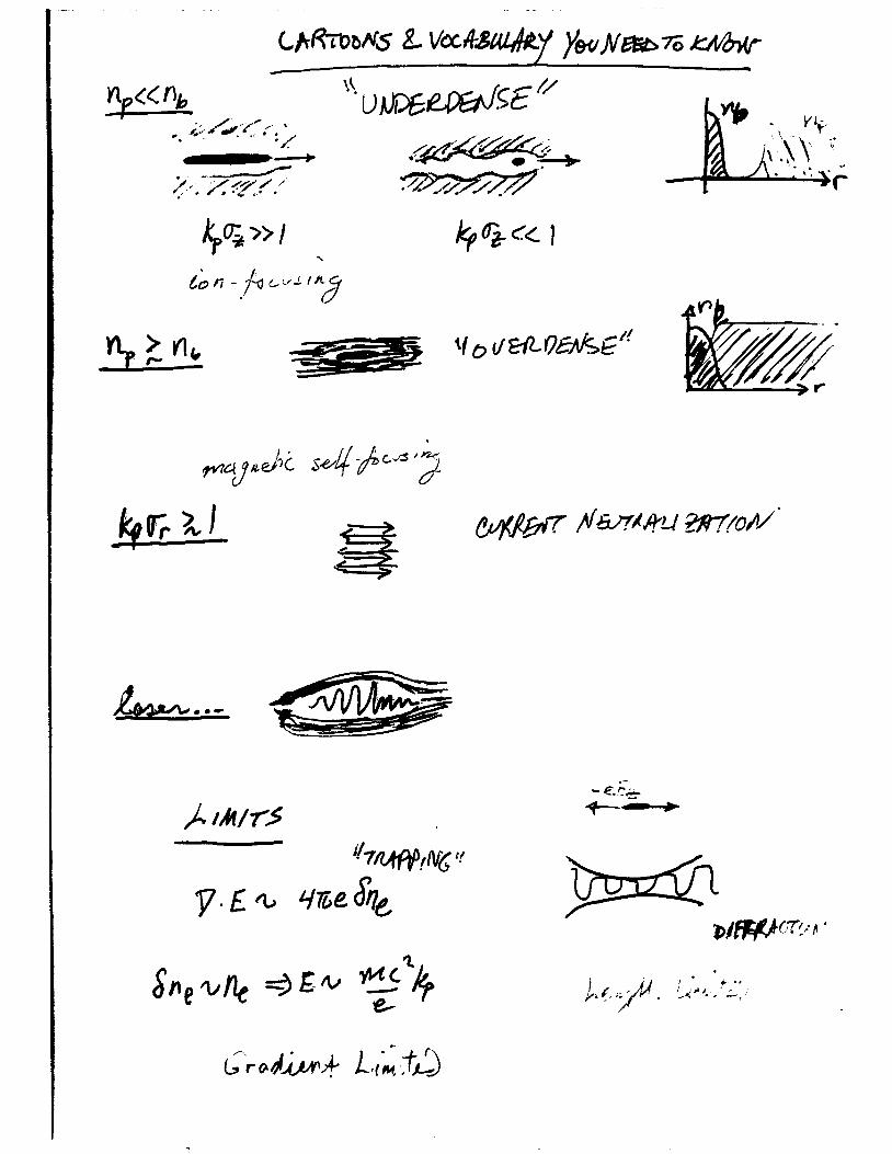
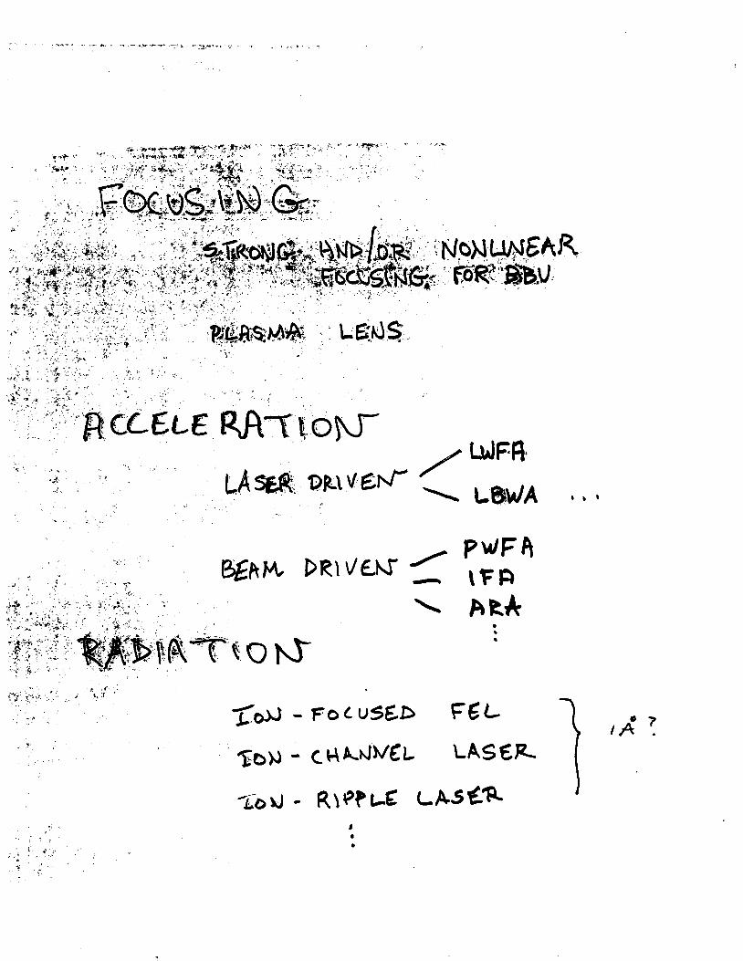
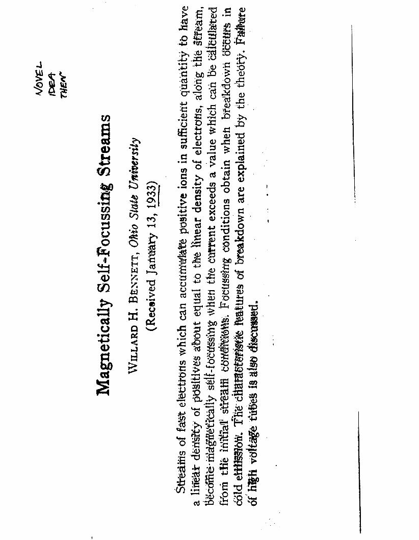
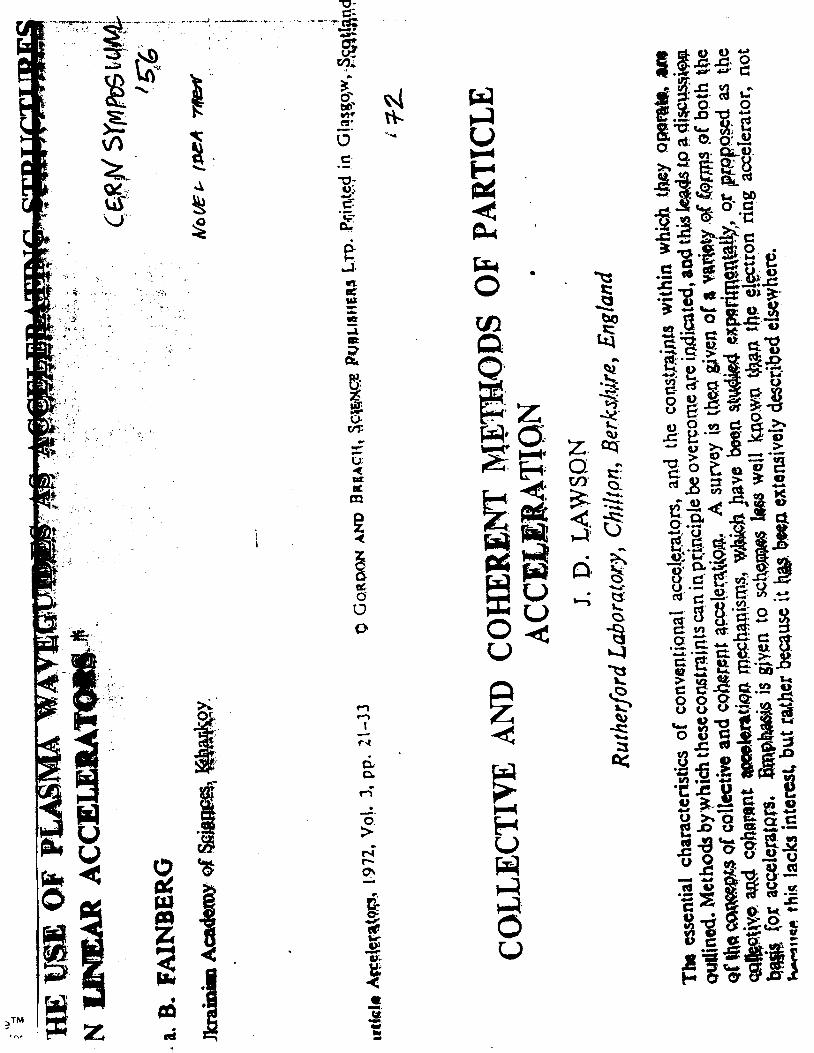
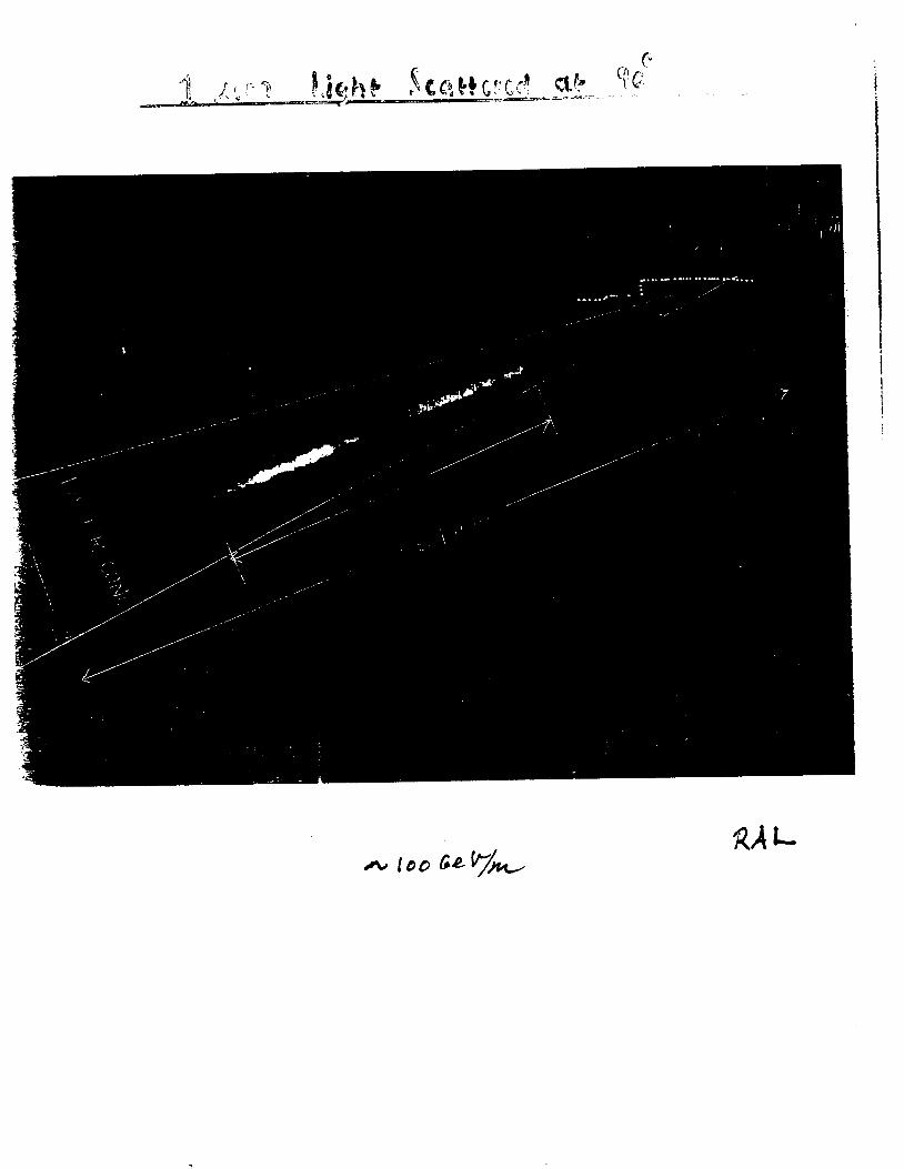
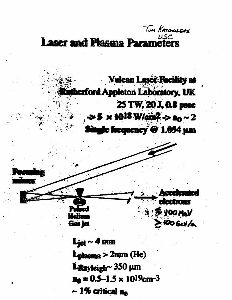
3397
0
E 5 Y
E U
s - m
8000
7000
6Ooo
5ooo
oooo 3000
2000 lo00
0
0 2e+14 amp+I4 amp+I4 amp+I4 le+lS 1 2 ~
X- y ------- -
- - -
3
1 I I I I 1 I I
0 5 10 15 20 25 ) 35
15
Figure 24 Calculated horizontal and venical spot sizes at IP-2 for a 1 ps slice with 03 relative energy spread The beam size is plotted as a function of plasma density
It is seen from Figure 24 that the spot sizes with and without the plasma cell are almost
identical for certain plasma densities The ldquotransparencyrdquo condition for the plasma cell was discussed earlier For minimum mismatch effects we expect a spot size for a single 1 ps slice of
better than 1 mm This is comparable to the spot size of the whole bunch The vertical deflection
Ay due to an acceleration of I GeV is
AiE Ay = D- = 33mm E
which is more than three times the vertical spot size The decelaration of the head will be about
05 GeV The expected dispersive shift of 16 mm is still larger than the spot size Assuming a
minimized beta mismatch of t k plasma cell the energy shifts of both head and tail of the bunch
should be easily observed
c Plasma dhgnostic
To be provided
A 3
2 L
e I
euro =
f
i
p I t I I I I I I
01 02 0
08
0 6
04
02
034
032
-002
i
__L_
W C -004
-006
0 0 5 1 15
lh5
tor
Q) v) 0 E L1 0 cn c (cr
0 0 0 0
amp a E
Q
- a - - - - -
t
1
0 l-4 I
Q)
m 0 E
Cr w 0 0
A a
I I
i
_
I I 2
E 3 I I I I i I
r( 0 rl
0- h
0 rn
0
T
I I I I I I I
B
9
1 I 1
I
I I 1 1 I I I
4 p
l a I I I I I 1
Of 5
- 0 -0 5
3 f
- i
1
05
- 0 5
- 1
-
-
I I I I
2 4 0 6 0 8 0 1 060 0 et z
A
C
P
0
ry rl 0
rl rc
1Oa
1 00
102
i 6
I
I
i
l
E 00
I I I I I I I
08 5 1 0 1 5 2 0 2 5 3 0
I I I I I
- MACRO
1 0 2 0 2 5 3 0 kpz
P
I
1 g f
[- i 1 f 1 f i m i w c a e l 1
E
v
0
wherc the tilde dciotes thl Lapltcc iisiorlll and p is the Laplace
transform variable Invertin thc Lab) c transforill the solution f o r
the beam centroid it
and we have useti G ( p ) = G lp 1 1 1 intcgral niily be c o m p u t e d
approximately by iiie methid of st^ t descents and the r e su l t
for the beam cenrroid disp1rcemcnr I
with exponent
L = 2 6 ~lO-~(gk f ) [ (w r~~~- y ] 2
Comparing this i t 1 Eq ( 5 ) one I-
been replaced with iie len_cli sci~le
more favorable s c ~ i i fig
that the length scale Ap h a s
iind varies IS (Q7 )-2 a much
For illustratiol we cosider a Ii Lrical exaniple corresponding
to a 25 TeV acccirator s i l i t h ioiis exiiiiiple we a s s u m e
17
bb2=05 and h=)bpm However i n iis cic wc assume injection
at a h i g h energy lOGeV (yF2x lo4) lsquoollowcd hy acceleration to
251TeV ( 5 - 5 ~ 10rdquo) The bcitroii piamp AD=(2y)rsquorsquo2i is initially 2 c m
and increases to 3amp1n at tiic csit k)tthcst parameters fixed w e
consider three cises cclti-rcsponclibt t o differcnt accelerating
gradients ( 1 ) 1 Gcrsquolm (2) I OGcrsquoii id (3) 1 OOGcVm Associated -- __c1_
parameters are listctl in Tahlc 1 To camp these scalings we solve EQ
9-
(41) numerically n i i h rcsuli inc l ic ird I I I Fig 3 Thc analytic results
are the dashed cives o Ila~cJ rh f ig 3 and they are almost
indistinguishable 1lsquo1 om the iiumcricI v4sults Eviclcntly only in t h e
lower gradient c a ~ i s the iiistahilit for concCrn
-
Y I
n
+ _ +
+ +
p =024clpamp =OIScm
U = O I J m t =48x1~cm-rabE=o9x1o- cm-~
F_Zimmemrm et 01 M A C
1i
crsquo
-
with
wits
i
1- gttp-+t
I = lp - +tp + +f - s
1 4 x lolo-
c w ~ w k neutralimtim in a plasma at the interaction point of an electron-gositron collidcr it c h q a ~ i j d i A for iha ptripodc of suppressing bcrmsirslrlung Conditions arc derived for good current ndi4r5amp tjy plasma return currents and the resulu of numerical simulations confirming the t amp q we rcpomxj Paramelerr arc presented for a TCV-CI~SS Linear Collidcr (TLC) employing pf-1 cunipcliwion nc problem of beam-plasma background reactions is noted
T~RX Rcginies in thc Plnsnia Compcnration Problcm
Very Early Time (1 tighly Colhionid Regime)
r gtgt r = (Q)rsquo Y-rsquo
Early Timc (hdoderrrtcly Collisional Rcgimc)
Laic Timc (Collisiotilcss Rcgimc)
v r ltlt 1
TABLE 111
Conditions for Good Current Compensation
16
1 J
12
8 2 00 a 7F at6
04
0 3 IO
7
6
5 c (n Q 3 4 - n - 3
1
O
1 I I I
-c
Nmr (ps)
0 0 2 0 4 0 6 0 8
0
8 O
02
35
30 - (
25 5 - N - 20
1 5
05
04 06 08 1 o Tlmr (ps)
0 02 0 4 06 00 10
08
O
06
a t CU a L
0 c
0
01
1 1
Vacuum Ficld I
1 - 2 3 4
rn
F1CItJRE 2 Tlrc riidiid coortlinrrte i s nornrafizcd by U w l w c tllc rildiirl bcam profile is exy ( - I u ) and kpu = 2
Examplc of Ihc ratlial profilc of the shicltlctl magnetic hchl in the collisionlcss regime 2 2
h
10
10
10 10 IO
kJ
10
10
kpa
FIGURE 4 Reduction in peak B field as 1 function of ku for a flat b u m
k z -
P i c
_ _ _ - -
amem orotcctor
-
C I
v) a P
Q) P 0 r
I
1
I W m m Acceleration Gradient
3
I E9 4 I
E
33 0 0 a m II II
m ti u
r h 4 0
1 4
E Igt c3
0 + 4
II II
I a
7
The Reach of High Energy Physics is limited by its instruments
accelerators
Today e245 60-M W klystrons running at 120 Hz to power a Two-Mile Linac producing 4000 Zrsquos per day Two 2200 m being cumm a B-Factory
3 Yeamp Next 6 Bring worked ~xercises Exercise No 1 Devise solutions to all problems at I GeVm 5 TeV c0m Exercise No 2 Devise Proof-of-Principle Experiments
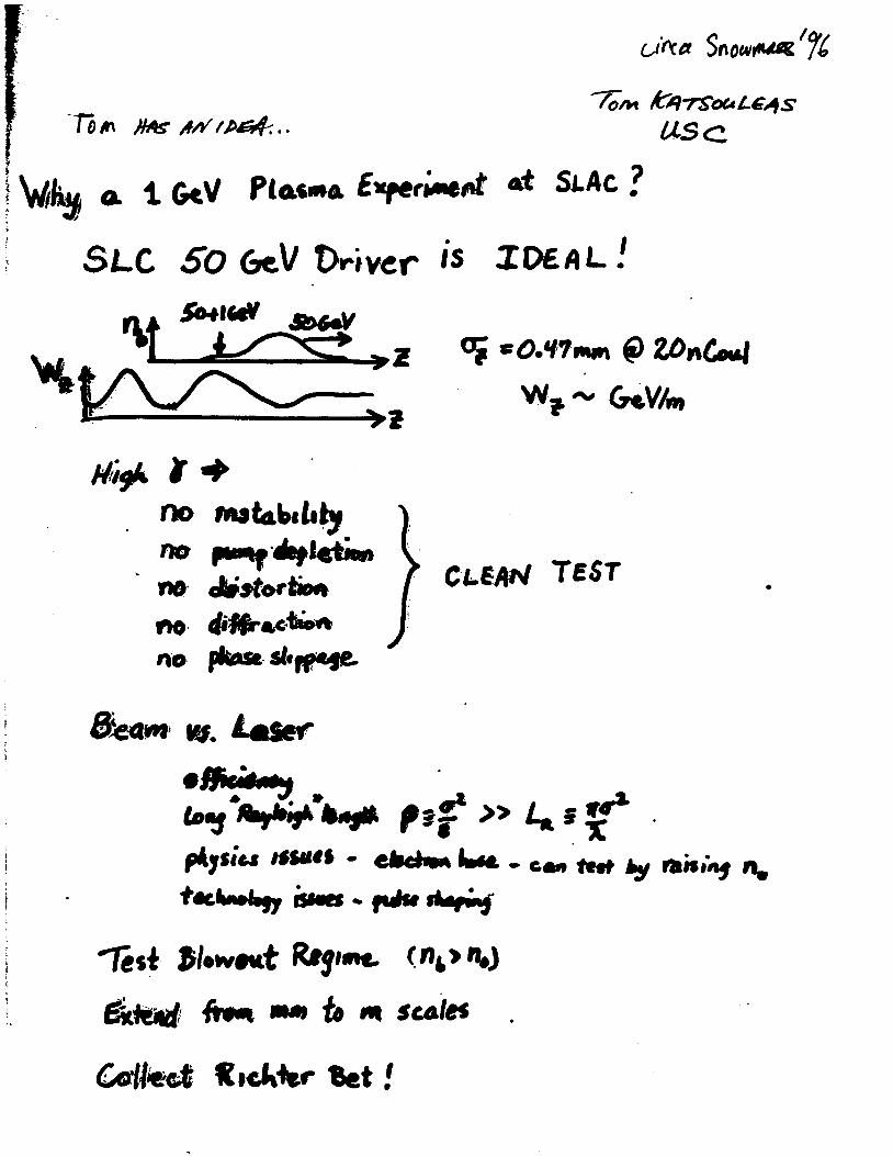
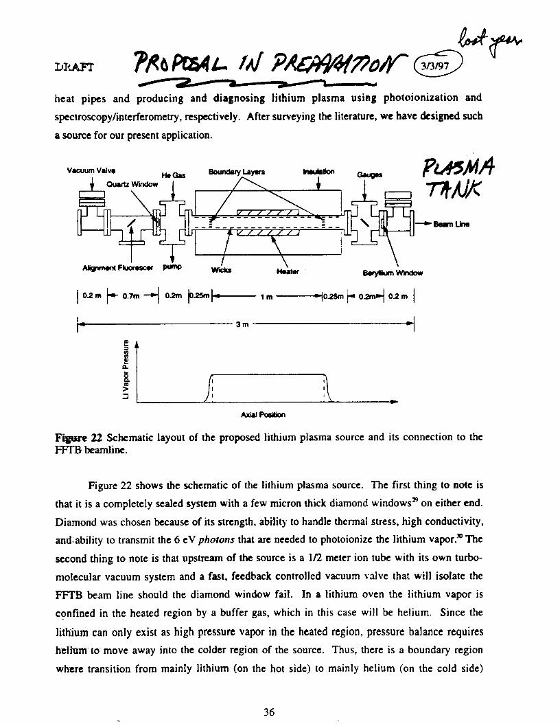
i
p I t I I I I I I
01 02 0
08
0 6
04
02
034
032
-002
i
__L_
W C -004
-006
0 0 5 1 15
lh5
tor
Q) v) 0 E L1 0 cn c (cr
0 0 0 0
amp a E
Q
- a - - - - -
t
1
0 l-4 I
Q)
m 0 E
Cr w 0 0
A a
I I
i
_
I I 2
E 3 I I I I i I
r( 0 rl
0- h
0 rn
0
T
I I I I I I I
B
9
1 I 1
I
I I 1 1 I I I
4 p
l a I I I I I 1
Of 5
- 0 -0 5
3 f
- i
1
05
- 0 5
- 1
-
-
I I I I
2 4 0 6 0 8 0 1 060 0 et z
A
C
P
0
ry rl 0
rl rc
1Oa
1 00
102
i 6
I
I
i
l
E 00
I I I I I I I
08 5 1 0 1 5 2 0 2 5 3 0
I I I I I
- MACRO
1 0 2 0 2 5 3 0 kpz
P
I
1 g f
[- i 1 f 1 f i m i w c a e l 1
E
v
0
wherc the tilde dciotes thl Lapltcc iisiorlll and p is the Laplace
transform variable Invertin thc Lab) c transforill the solution f o r
the beam centroid it
and we have useti G ( p ) = G lp 1 1 1 intcgral niily be c o m p u t e d
approximately by iiie methid of st^ t descents and the r e su l t
for the beam cenrroid disp1rcemcnr I
with exponent
L = 2 6 ~lO-~(gk f ) [ (w r~~~- y ] 2
Comparing this i t 1 Eq ( 5 ) one I-
been replaced with iie len_cli sci~le
more favorable s c ~ i i fig
that the length scale Ap h a s
iind varies IS (Q7 )-2 a much
For illustratiol we cosider a Ii Lrical exaniple corresponding
to a 25 TeV acccirator s i l i t h ioiis exiiiiiple we a s s u m e
17
bb2=05 and h=)bpm However i n iis cic wc assume injection
at a h i g h energy lOGeV (yF2x lo4) lsquoollowcd hy acceleration to
251TeV ( 5 - 5 ~ 10rdquo) The bcitroii piamp AD=(2y)rsquorsquo2i is initially 2 c m
and increases to 3amp1n at tiic csit k)tthcst parameters fixed w e
consider three cises cclti-rcsponclibt t o differcnt accelerating
gradients ( 1 ) 1 Gcrsquolm (2) I OGcrsquoii id (3) 1 OOGcVm Associated -- __c1_
parameters are listctl in Tahlc 1 To camp these scalings we solve EQ
9-
(41) numerically n i i h rcsuli inc l ic ird I I I Fig 3 Thc analytic results
are the dashed cives o Ila~cJ rh f ig 3 and they are almost
indistinguishable 1lsquo1 om the iiumcricI v4sults Eviclcntly only in t h e
lower gradient c a ~ i s the iiistahilit for concCrn
-
Y I
n
+ _ +
+ +
p =024clpamp =OIScm
U = O I J m t =48x1~cm-rabE=o9x1o- cm-~
F_Zimmemrm et 01 M A C
1i
crsquo
-
with
wits
i
1- gttp-+t
I = lp - +tp + +f - s
1 4 x lolo-
c w ~ w k neutralimtim in a plasma at the interaction point of an electron-gositron collidcr it c h q a ~ i j d i A for iha ptripodc of suppressing bcrmsirslrlung Conditions arc derived for good current ndi4r5amp tjy plasma return currents and the resulu of numerical simulations confirming the t amp q we rcpomxj Paramelerr arc presented for a TCV-CI~SS Linear Collidcr (TLC) employing pf-1 cunipcliwion nc problem of beam-plasma background reactions is noted
T~RX Rcginies in thc Plnsnia Compcnration Problcm
Very Early Time (1 tighly Colhionid Regime)
r gtgt r = (Q)rsquo Y-rsquo
Early Timc (hdoderrrtcly Collisional Rcgimc)
Laic Timc (Collisiotilcss Rcgimc)
v r ltlt 1
TABLE 111
Conditions for Good Current Compensation
16
1 J
12
8 2 00 a 7F at6
04
0 3 IO
7
6
5 c (n Q 3 4 - n - 3
1
O
1 I I I
-c
Nmr (ps)
0 0 2 0 4 0 6 0 8
0
8 O
02
35
30 - (
25 5 - N - 20
1 5
05
04 06 08 1 o Tlmr (ps)
0 02 0 4 06 00 10
08
O
06
a t CU a L
0 c
0
01
1 1
Vacuum Ficld I
1 - 2 3 4
rn
F1CItJRE 2 Tlrc riidiid coortlinrrte i s nornrafizcd by U w l w c tllc rildiirl bcam profile is exy ( - I u ) and kpu = 2
Examplc of Ihc ratlial profilc of the shicltlctl magnetic hchl in the collisionlcss regime 2 2
h
10
10
10 10 IO
kJ
10
10
kpa
FIGURE 4 Reduction in peak B field as 1 function of ku for a flat b u m
k z -
P i c
_ _ _ - -
amem orotcctor
-
C I
v) a P
Q) P 0 r
I
1
I W m m Acceleration Gradient
3
I E9 4 I
E
33 0 0 a m II II
m ti u
r h 4 0
1 4
E Igt c3
0 + 4
II II
I a
7
The Reach of High Energy Physics is limited by its instruments
accelerators
Today e245 60-M W klystrons running at 120 Hz to power a Two-Mile Linac producing 4000 Zrsquos per day Two 2200 m being cumm a B-Factory
3 Yeamp Next 6 Bring worked ~xercises Exercise No 1 Devise solutions to all problems at I GeVm 5 TeV c0m Exercise No 2 Devise Proof-of-Principle Experiments
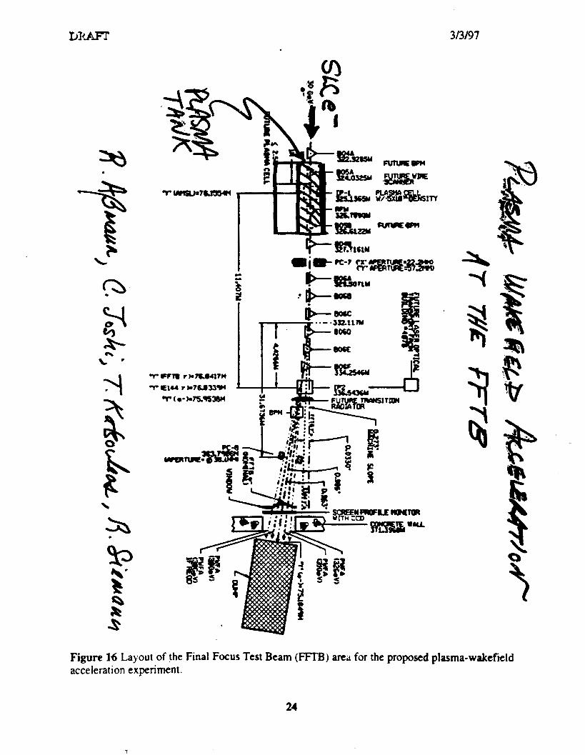
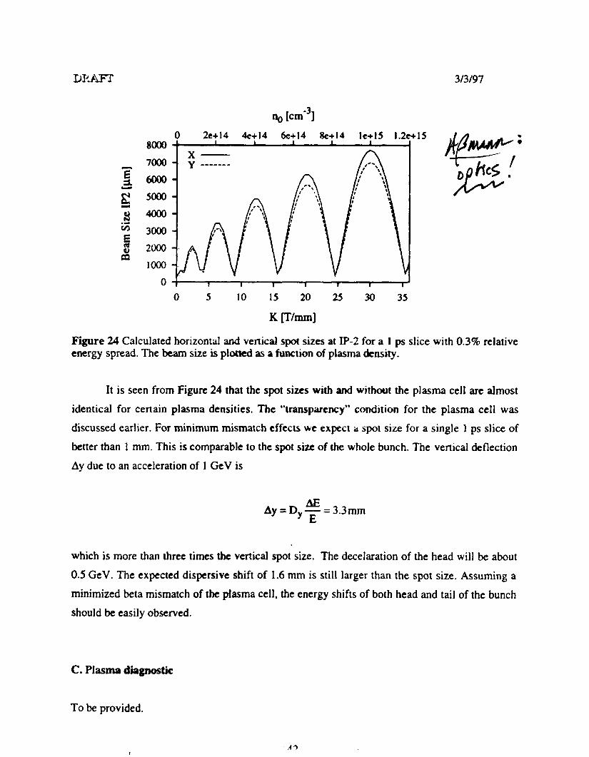
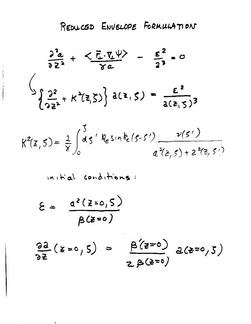
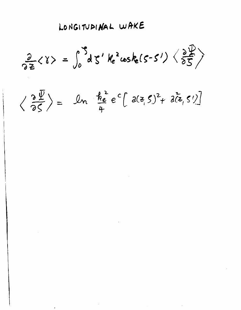
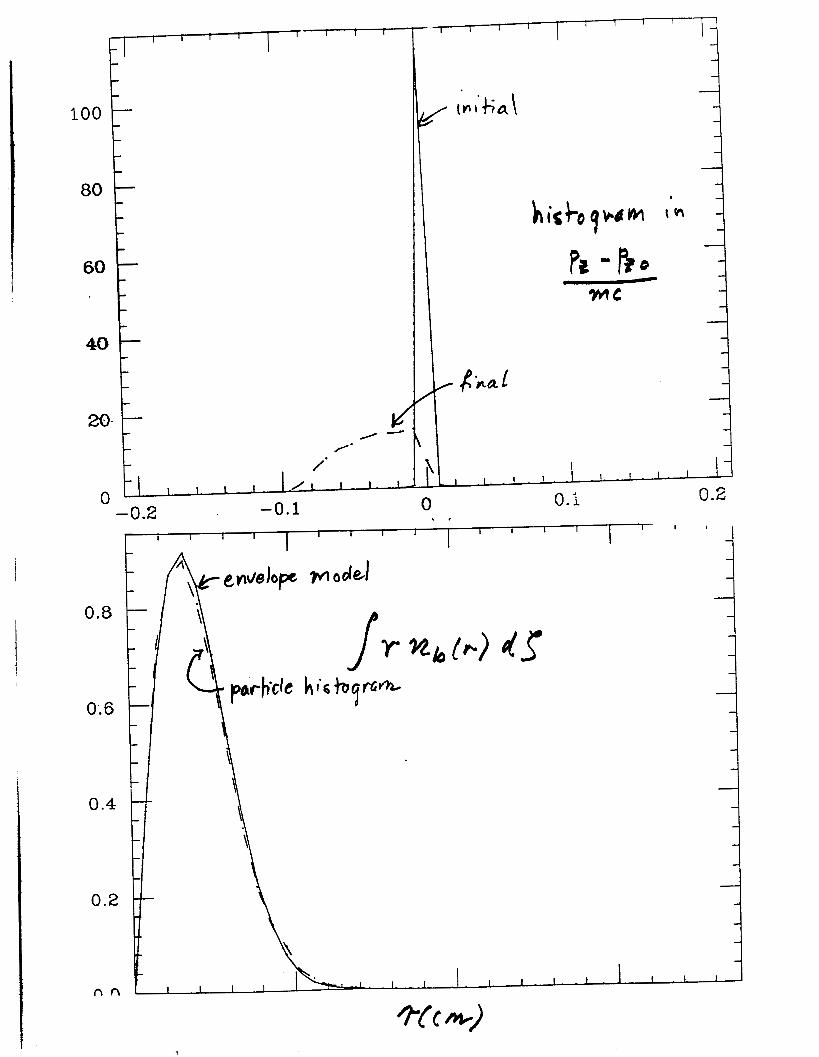
i
_
I I 2
E 3 I I I I i I
r( 0 rl
0- h
0 rn
0
T
I I I I I I I
B
9
1 I 1
I
I I 1 1 I I I
4 p
l a I I I I I 1
Of 5
- 0 -0 5
3 f
- i
1
05
- 0 5
- 1
-
-
I I I I
2 4 0 6 0 8 0 1 060 0 et z
A
C
P
0
ry rl 0
rl rc
1Oa
1 00
102
i 6
I
I
i
l
E 00
I I I I I I I
08 5 1 0 1 5 2 0 2 5 3 0
I I I I I
- MACRO
1 0 2 0 2 5 3 0 kpz
P
I
1 g f
[- i 1 f 1 f i m i w c a e l 1
E
v
0
wherc the tilde dciotes thl Lapltcc iisiorlll and p is the Laplace
transform variable Invertin thc Lab) c transforill the solution f o r
the beam centroid it
and we have useti G ( p ) = G lp 1 1 1 intcgral niily be c o m p u t e d
approximately by iiie methid of st^ t descents and the r e su l t
for the beam cenrroid disp1rcemcnr I
with exponent
L = 2 6 ~lO-~(gk f ) [ (w r~~~- y ] 2
Comparing this i t 1 Eq ( 5 ) one I-
been replaced with iie len_cli sci~le
more favorable s c ~ i i fig
that the length scale Ap h a s
iind varies IS (Q7 )-2 a much
For illustratiol we cosider a Ii Lrical exaniple corresponding
to a 25 TeV acccirator s i l i t h ioiis exiiiiiple we a s s u m e
17
bb2=05 and h=)bpm However i n iis cic wc assume injection
at a h i g h energy lOGeV (yF2x lo4) lsquoollowcd hy acceleration to
251TeV ( 5 - 5 ~ 10rdquo) The bcitroii piamp AD=(2y)rsquorsquo2i is initially 2 c m
and increases to 3amp1n at tiic csit k)tthcst parameters fixed w e
consider three cises cclti-rcsponclibt t o differcnt accelerating
gradients ( 1 ) 1 Gcrsquolm (2) I OGcrsquoii id (3) 1 OOGcVm Associated -- __c1_
parameters are listctl in Tahlc 1 To camp these scalings we solve EQ
9-
(41) numerically n i i h rcsuli inc l ic ird I I I Fig 3 Thc analytic results
are the dashed cives o Ila~cJ rh f ig 3 and they are almost
indistinguishable 1lsquo1 om the iiumcricI v4sults Eviclcntly only in t h e
lower gradient c a ~ i s the iiistahilit for concCrn
-
Y I
n
+ _ +
+ +
p =024clpamp =OIScm
U = O I J m t =48x1~cm-rabE=o9x1o- cm-~
F_Zimmemrm et 01 M A C
1i
crsquo
-
with
wits
i
1- gttp-+t
I = lp - +tp + +f - s
1 4 x lolo-
c w ~ w k neutralimtim in a plasma at the interaction point of an electron-gositron collidcr it c h q a ~ i j d i A for iha ptripodc of suppressing bcrmsirslrlung Conditions arc derived for good current ndi4r5amp tjy plasma return currents and the resulu of numerical simulations confirming the t amp q we rcpomxj Paramelerr arc presented for a TCV-CI~SS Linear Collidcr (TLC) employing pf-1 cunipcliwion nc problem of beam-plasma background reactions is noted
T~RX Rcginies in thc Plnsnia Compcnration Problcm
Very Early Time (1 tighly Colhionid Regime)
r gtgt r = (Q)rsquo Y-rsquo
Early Timc (hdoderrrtcly Collisional Rcgimc)
Laic Timc (Collisiotilcss Rcgimc)
v r ltlt 1
TABLE 111
Conditions for Good Current Compensation
16
1 J
12
8 2 00 a 7F at6
04
0 3 IO
7
6
5 c (n Q 3 4 - n - 3
1
O
1 I I I
-c
Nmr (ps)
0 0 2 0 4 0 6 0 8
0
8 O
02
35
30 - (
25 5 - N - 20
1 5
05
04 06 08 1 o Tlmr (ps)
0 02 0 4 06 00 10
08
O
06
a t CU a L
0 c
0
01
1 1
Vacuum Ficld I
1 - 2 3 4
rn
F1CItJRE 2 Tlrc riidiid coortlinrrte i s nornrafizcd by U w l w c tllc rildiirl bcam profile is exy ( - I u ) and kpu = 2
Examplc of Ihc ratlial profilc of the shicltlctl magnetic hchl in the collisionlcss regime 2 2
h
10
10
10 10 IO
kJ
10
10
kpa
FIGURE 4 Reduction in peak B field as 1 function of ku for a flat b u m
k z -
P i c
_ _ _ - -
amem orotcctor
-
C I
v) a P
Q) P 0 r
I
1
I W m m Acceleration Gradient
3
I E9 4 I
E
33 0 0 a m II II
m ti u
r h 4 0
1 4
E Igt c3
0 + 4
II II
I a
7
The Reach of High Energy Physics is limited by its instruments
accelerators
Today e245 60-M W klystrons running at 120 Hz to power a Two-Mile Linac producing 4000 Zrsquos per day Two 2200 m being cumm a B-Factory
3 Yeamp Next 6 Bring worked ~xercises Exercise No 1 Devise solutions to all problems at I GeVm 5 TeV c0m Exercise No 2 Devise Proof-of-Principle Experiments
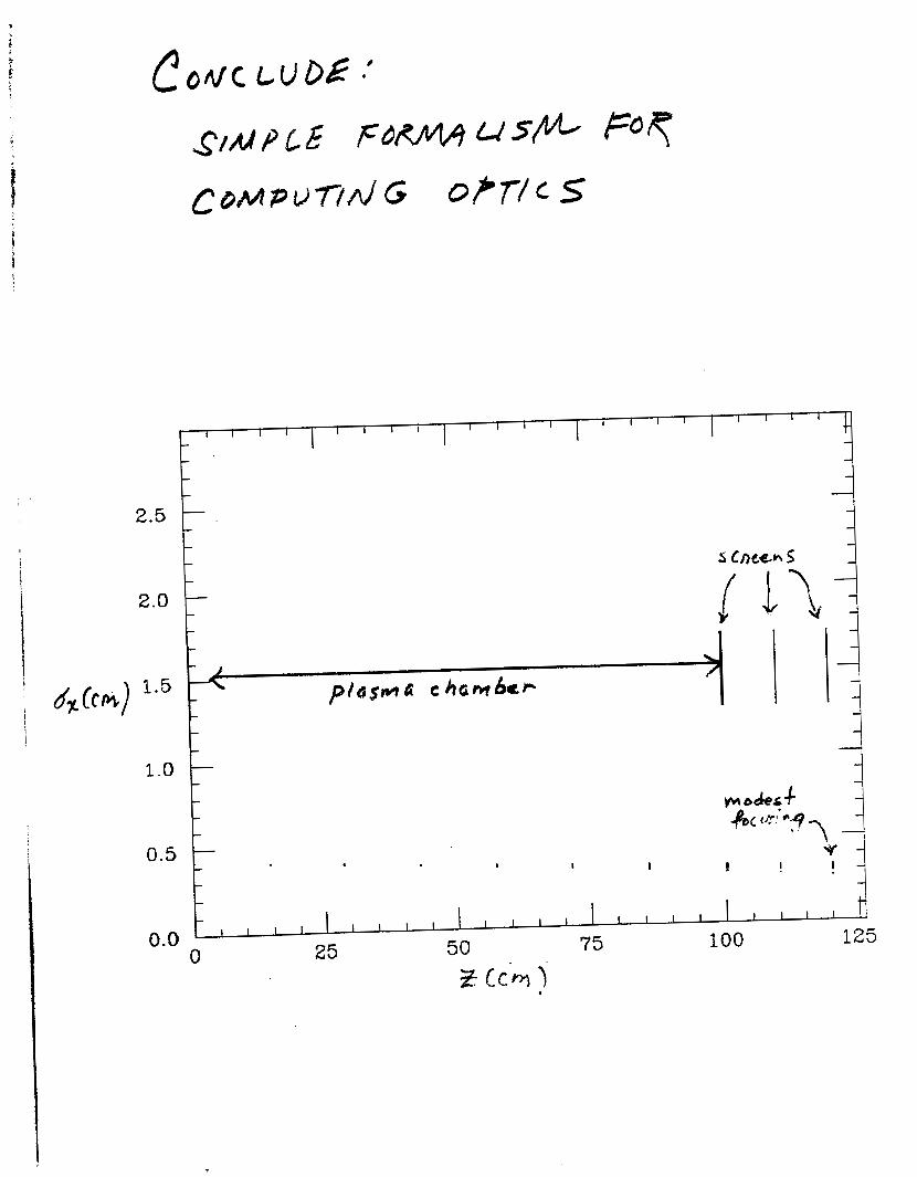
I I I I I I I
B
9
1 I 1
I
I I 1 1 I I I
4 p
l a I I I I I 1
Of 5
- 0 -0 5
3 f
- i
1
05
- 0 5
- 1
-
-
I I I I
2 4 0 6 0 8 0 1 060 0 et z
A
C
P
0
ry rl 0
rl rc
1Oa
1 00
102
i 6
I
I
i
l
E 00
I I I I I I I
08 5 1 0 1 5 2 0 2 5 3 0
I I I I I
- MACRO
1 0 2 0 2 5 3 0 kpz
P
I
1 g f
[- i 1 f 1 f i m i w c a e l 1
E
v
0
wherc the tilde dciotes thl Lapltcc iisiorlll and p is the Laplace
transform variable Invertin thc Lab) c transforill the solution f o r
the beam centroid it
and we have useti G ( p ) = G lp 1 1 1 intcgral niily be c o m p u t e d
approximately by iiie methid of st^ t descents and the r e su l t
for the beam cenrroid disp1rcemcnr I
with exponent
L = 2 6 ~lO-~(gk f ) [ (w r~~~- y ] 2
Comparing this i t 1 Eq ( 5 ) one I-
been replaced with iie len_cli sci~le
more favorable s c ~ i i fig
that the length scale Ap h a s
iind varies IS (Q7 )-2 a much
For illustratiol we cosider a Ii Lrical exaniple corresponding
to a 25 TeV acccirator s i l i t h ioiis exiiiiiple we a s s u m e
17
bb2=05 and h=)bpm However i n iis cic wc assume injection
at a h i g h energy lOGeV (yF2x lo4) lsquoollowcd hy acceleration to
251TeV ( 5 - 5 ~ 10rdquo) The bcitroii piamp AD=(2y)rsquorsquo2i is initially 2 c m
and increases to 3amp1n at tiic csit k)tthcst parameters fixed w e
consider three cises cclti-rcsponclibt t o differcnt accelerating
gradients ( 1 ) 1 Gcrsquolm (2) I OGcrsquoii id (3) 1 OOGcVm Associated -- __c1_
parameters are listctl in Tahlc 1 To camp these scalings we solve EQ
9-
(41) numerically n i i h rcsuli inc l ic ird I I I Fig 3 Thc analytic results
are the dashed cives o Ila~cJ rh f ig 3 and they are almost
indistinguishable 1lsquo1 om the iiumcricI v4sults Eviclcntly only in t h e
lower gradient c a ~ i s the iiistahilit for concCrn
-
Y I
n
+ _ +
+ +
p =024clpamp =OIScm
U = O I J m t =48x1~cm-rabE=o9x1o- cm-~
F_Zimmemrm et 01 M A C
1i
crsquo
-
with
wits
i
1- gttp-+t
I = lp - +tp + +f - s
1 4 x lolo-
c w ~ w k neutralimtim in a plasma at the interaction point of an electron-gositron collidcr it c h q a ~ i j d i A for iha ptripodc of suppressing bcrmsirslrlung Conditions arc derived for good current ndi4r5amp tjy plasma return currents and the resulu of numerical simulations confirming the t amp q we rcpomxj Paramelerr arc presented for a TCV-CI~SS Linear Collidcr (TLC) employing pf-1 cunipcliwion nc problem of beam-plasma background reactions is noted
T~RX Rcginies in thc Plnsnia Compcnration Problcm
Very Early Time (1 tighly Colhionid Regime)
r gtgt r = (Q)rsquo Y-rsquo
Early Timc (hdoderrrtcly Collisional Rcgimc)
Laic Timc (Collisiotilcss Rcgimc)
v r ltlt 1
TABLE 111
Conditions for Good Current Compensation
16
1 J
12
8 2 00 a 7F at6
04
0 3 IO
7
6
5 c (n Q 3 4 - n - 3
1
O
1 I I I
-c
Nmr (ps)
0 0 2 0 4 0 6 0 8
0
8 O
02
35
30 - (
25 5 - N - 20
1 5
05
04 06 08 1 o Tlmr (ps)
0 02 0 4 06 00 10
08
O
06
a t CU a L
0 c
0
01
1 1
Vacuum Ficld I
1 - 2 3 4
rn
F1CItJRE 2 Tlrc riidiid coortlinrrte i s nornrafizcd by U w l w c tllc rildiirl bcam profile is exy ( - I u ) and kpu = 2
Examplc of Ihc ratlial profilc of the shicltlctl magnetic hchl in the collisionlcss regime 2 2
h
10
10
10 10 IO
kJ
10
10
kpa
FIGURE 4 Reduction in peak B field as 1 function of ku for a flat b u m
k z -
P i c
_ _ _ - -
amem orotcctor
-
C I
v) a P
Q) P 0 r
I
1
I W m m Acceleration Gradient
3
I E9 4 I
E
33 0 0 a m II II
m ti u
r h 4 0
1 4
E Igt c3
0 + 4
II II
I a
7
The Reach of High Energy Physics is limited by its instruments
accelerators
Today e245 60-M W klystrons running at 120 Hz to power a Two-Mile Linac producing 4000 Zrsquos per day Two 2200 m being cumm a B-Factory
3 Yeamp Next 6 Bring worked ~xercises Exercise No 1 Devise solutions to all problems at I GeVm 5 TeV c0m Exercise No 2 Devise Proof-of-Principle Experiments
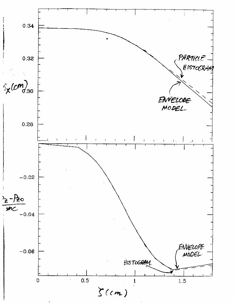
0
ry rl 0
rl rc
1Oa
1 00
102
i 6
I
I
i
l
E 00
I I I I I I I
08 5 1 0 1 5 2 0 2 5 3 0
I I I I I
- MACRO
1 0 2 0 2 5 3 0 kpz
P
I
1 g f
[- i 1 f 1 f i m i w c a e l 1
E
v
0
wherc the tilde dciotes thl Lapltcc iisiorlll and p is the Laplace
transform variable Invertin thc Lab) c transforill the solution f o r
the beam centroid it
and we have useti G ( p ) = G lp 1 1 1 intcgral niily be c o m p u t e d
approximately by iiie methid of st^ t descents and the r e su l t
for the beam cenrroid disp1rcemcnr I
with exponent
L = 2 6 ~lO-~(gk f ) [ (w r~~~- y ] 2
Comparing this i t 1 Eq ( 5 ) one I-
been replaced with iie len_cli sci~le
more favorable s c ~ i i fig
that the length scale Ap h a s
iind varies IS (Q7 )-2 a much
For illustratiol we cosider a Ii Lrical exaniple corresponding
to a 25 TeV acccirator s i l i t h ioiis exiiiiiple we a s s u m e
17
bb2=05 and h=)bpm However i n iis cic wc assume injection
at a h i g h energy lOGeV (yF2x lo4) lsquoollowcd hy acceleration to
251TeV ( 5 - 5 ~ 10rdquo) The bcitroii piamp AD=(2y)rsquorsquo2i is initially 2 c m
and increases to 3amp1n at tiic csit k)tthcst parameters fixed w e
consider three cises cclti-rcsponclibt t o differcnt accelerating
gradients ( 1 ) 1 Gcrsquolm (2) I OGcrsquoii id (3) 1 OOGcVm Associated -- __c1_
parameters are listctl in Tahlc 1 To camp these scalings we solve EQ
9-
(41) numerically n i i h rcsuli inc l ic ird I I I Fig 3 Thc analytic results
are the dashed cives o Ila~cJ rh f ig 3 and they are almost
indistinguishable 1lsquo1 om the iiumcricI v4sults Eviclcntly only in t h e
lower gradient c a ~ i s the iiistahilit for concCrn
-
Y I
n
+ _ +
+ +
p =024clpamp =OIScm
U = O I J m t =48x1~cm-rabE=o9x1o- cm-~
F_Zimmemrm et 01 M A C
1i
crsquo
-
with
wits
i
1- gttp-+t
I = lp - +tp + +f - s
1 4 x lolo-
c w ~ w k neutralimtim in a plasma at the interaction point of an electron-gositron collidcr it c h q a ~ i j d i A for iha ptripodc of suppressing bcrmsirslrlung Conditions arc derived for good current ndi4r5amp tjy plasma return currents and the resulu of numerical simulations confirming the t amp q we rcpomxj Paramelerr arc presented for a TCV-CI~SS Linear Collidcr (TLC) employing pf-1 cunipcliwion nc problem of beam-plasma background reactions is noted
T~RX Rcginies in thc Plnsnia Compcnration Problcm
Very Early Time (1 tighly Colhionid Regime)
r gtgt r = (Q)rsquo Y-rsquo
Early Timc (hdoderrrtcly Collisional Rcgimc)
Laic Timc (Collisiotilcss Rcgimc)
v r ltlt 1
TABLE 111
Conditions for Good Current Compensation
16
1 J
12
8 2 00 a 7F at6
04
0 3 IO
7
6
5 c (n Q 3 4 - n - 3
1
O
1 I I I
-c
Nmr (ps)
0 0 2 0 4 0 6 0 8
0
8 O
02
35
30 - (
25 5 - N - 20
1 5
05
04 06 08 1 o Tlmr (ps)
0 02 0 4 06 00 10
08
O
06
a t CU a L
0 c
0
01
1 1
Vacuum Ficld I
1 - 2 3 4
rn
F1CItJRE 2 Tlrc riidiid coortlinrrte i s nornrafizcd by U w l w c tllc rildiirl bcam profile is exy ( - I u ) and kpu = 2
Examplc of Ihc ratlial profilc of the shicltlctl magnetic hchl in the collisionlcss regime 2 2
h
10
10
10 10 IO
kJ
10
10
kpa
FIGURE 4 Reduction in peak B field as 1 function of ku for a flat b u m
k z -
P i c
_ _ _ - -
amem orotcctor
-
C I
v) a P
Q) P 0 r
I
1
I W m m Acceleration Gradient
3
I E9 4 I
E
33 0 0 a m II II
m ti u
r h 4 0
1 4
E Igt c3
0 + 4
II II
I a
7
The Reach of High Energy Physics is limited by its instruments
accelerators
Today e245 60-M W klystrons running at 120 Hz to power a Two-Mile Linac producing 4000 Zrsquos per day Two 2200 m being cumm a B-Factory
3 Yeamp Next 6 Bring worked ~xercises Exercise No 1 Devise solutions to all problems at I GeVm 5 TeV c0m Exercise No 2 Devise Proof-of-Principle Experiments
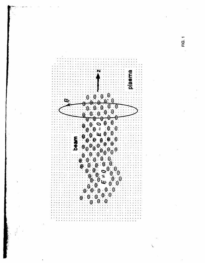

I
1 g f
[- i 1 f 1 f i m i w c a e l 1
E
v
0
wherc the tilde dciotes thl Lapltcc iisiorlll and p is the Laplace
transform variable Invertin thc Lab) c transforill the solution f o r
the beam centroid it
and we have useti G ( p ) = G lp 1 1 1 intcgral niily be c o m p u t e d
approximately by iiie methid of st^ t descents and the r e su l t
for the beam cenrroid disp1rcemcnr I
with exponent
L = 2 6 ~lO-~(gk f ) [ (w r~~~- y ] 2
Comparing this i t 1 Eq ( 5 ) one I-
been replaced with iie len_cli sci~le
more favorable s c ~ i i fig
that the length scale Ap h a s
iind varies IS (Q7 )-2 a much
For illustratiol we cosider a Ii Lrical exaniple corresponding
to a 25 TeV acccirator s i l i t h ioiis exiiiiiple we a s s u m e
17
bb2=05 and h=)bpm However i n iis cic wc assume injection
at a h i g h energy lOGeV (yF2x lo4) lsquoollowcd hy acceleration to
251TeV ( 5 - 5 ~ 10rdquo) The bcitroii piamp AD=(2y)rsquorsquo2i is initially 2 c m
and increases to 3amp1n at tiic csit k)tthcst parameters fixed w e
consider three cises cclti-rcsponclibt t o differcnt accelerating
gradients ( 1 ) 1 Gcrsquolm (2) I OGcrsquoii id (3) 1 OOGcVm Associated -- __c1_
parameters are listctl in Tahlc 1 To camp these scalings we solve EQ
9-
(41) numerically n i i h rcsuli inc l ic ird I I I Fig 3 Thc analytic results
are the dashed cives o Ila~cJ rh f ig 3 and they are almost
indistinguishable 1lsquo1 om the iiumcricI v4sults Eviclcntly only in t h e
lower gradient c a ~ i s the iiistahilit for concCrn
-
Y I
n
+ _ +
+ +
p =024clpamp =OIScm
U = O I J m t =48x1~cm-rabE=o9x1o- cm-~
F_Zimmemrm et 01 M A C
1i
crsquo
-
with
wits
i
1- gttp-+t
I = lp - +tp + +f - s
1 4 x lolo-
c w ~ w k neutralimtim in a plasma at the interaction point of an electron-gositron collidcr it c h q a ~ i j d i A for iha ptripodc of suppressing bcrmsirslrlung Conditions arc derived for good current ndi4r5amp tjy plasma return currents and the resulu of numerical simulations confirming the t amp q we rcpomxj Paramelerr arc presented for a TCV-CI~SS Linear Collidcr (TLC) employing pf-1 cunipcliwion nc problem of beam-plasma background reactions is noted
T~RX Rcginies in thc Plnsnia Compcnration Problcm
Very Early Time (1 tighly Colhionid Regime)
r gtgt r = (Q)rsquo Y-rsquo
Early Timc (hdoderrrtcly Collisional Rcgimc)
Laic Timc (Collisiotilcss Rcgimc)
v r ltlt 1
TABLE 111
Conditions for Good Current Compensation
16
1 J
12
8 2 00 a 7F at6
04
0 3 IO
7
6
5 c (n Q 3 4 - n - 3
1
O
1 I I I
-c
Nmr (ps)
0 0 2 0 4 0 6 0 8
0
8 O
02
35
30 - (
25 5 - N - 20
1 5
05
04 06 08 1 o Tlmr (ps)
0 02 0 4 06 00 10
08
O
06
a t CU a L
0 c
0
01
1 1
Vacuum Ficld I
1 - 2 3 4
rn
F1CItJRE 2 Tlrc riidiid coortlinrrte i s nornrafizcd by U w l w c tllc rildiirl bcam profile is exy ( - I u ) and kpu = 2
Examplc of Ihc ratlial profilc of the shicltlctl magnetic hchl in the collisionlcss regime 2 2
h
10
10
10 10 IO
kJ
10
10
kpa
FIGURE 4 Reduction in peak B field as 1 function of ku for a flat b u m
k z -
P i c
_ _ _ - -
amem orotcctor
-
C I
v) a P
Q) P 0 r
I
1
I W m m Acceleration Gradient
3
I E9 4 I
E
33 0 0 a m II II
m ti u
r h 4 0
1 4
E Igt c3
0 + 4
II II
I a
7
The Reach of High Energy Physics is limited by its instruments
accelerators
Today e245 60-M W klystrons running at 120 Hz to power a Two-Mile Linac producing 4000 Zrsquos per day Two 2200 m being cumm a B-Factory
3 Yeamp Next 6 Bring worked ~xercises Exercise No 1 Devise solutions to all problems at I GeVm 5 TeV c0m Exercise No 2 Devise Proof-of-Principle Experiments
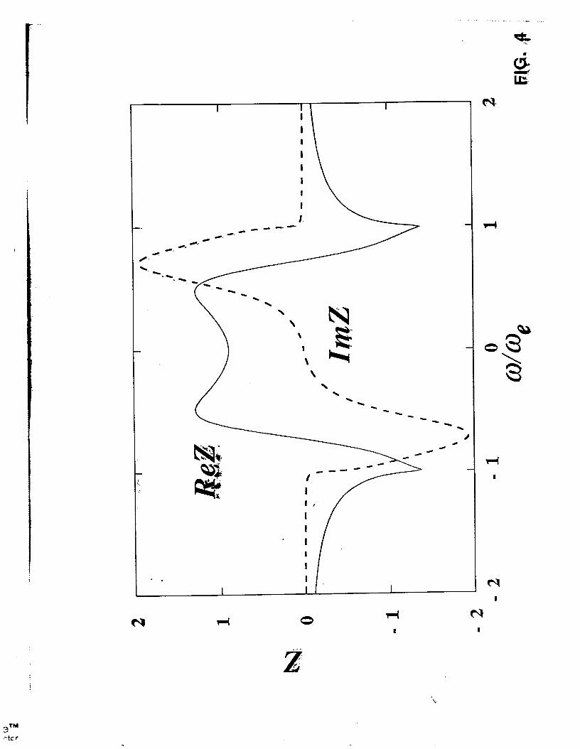
E
v
0
wherc the tilde dciotes thl Lapltcc iisiorlll and p is the Laplace
transform variable Invertin thc Lab) c transforill the solution f o r
the beam centroid it
and we have useti G ( p ) = G lp 1 1 1 intcgral niily be c o m p u t e d
approximately by iiie methid of st^ t descents and the r e su l t
for the beam cenrroid disp1rcemcnr I
with exponent
L = 2 6 ~lO-~(gk f ) [ (w r~~~- y ] 2
Comparing this i t 1 Eq ( 5 ) one I-
been replaced with iie len_cli sci~le
more favorable s c ~ i i fig
that the length scale Ap h a s
iind varies IS (Q7 )-2 a much
For illustratiol we cosider a Ii Lrical exaniple corresponding
to a 25 TeV acccirator s i l i t h ioiis exiiiiiple we a s s u m e
17
bb2=05 and h=)bpm However i n iis cic wc assume injection
at a h i g h energy lOGeV (yF2x lo4) lsquoollowcd hy acceleration to
251TeV ( 5 - 5 ~ 10rdquo) The bcitroii piamp AD=(2y)rsquorsquo2i is initially 2 c m
and increases to 3amp1n at tiic csit k)tthcst parameters fixed w e
consider three cises cclti-rcsponclibt t o differcnt accelerating
gradients ( 1 ) 1 Gcrsquolm (2) I OGcrsquoii id (3) 1 OOGcVm Associated -- __c1_
parameters are listctl in Tahlc 1 To camp these scalings we solve EQ
9-
(41) numerically n i i h rcsuli inc l ic ird I I I Fig 3 Thc analytic results
are the dashed cives o Ila~cJ rh f ig 3 and they are almost
indistinguishable 1lsquo1 om the iiumcricI v4sults Eviclcntly only in t h e
lower gradient c a ~ i s the iiistahilit for concCrn
-
Y I
n
+ _ +
+ +
p =024clpamp =OIScm
U = O I J m t =48x1~cm-rabE=o9x1o- cm-~
F_Zimmemrm et 01 M A C
1i
crsquo
-
with
wits
i
1- gttp-+t
I = lp - +tp + +f - s
1 4 x lolo-
c w ~ w k neutralimtim in a plasma at the interaction point of an electron-gositron collidcr it c h q a ~ i j d i A for iha ptripodc of suppressing bcrmsirslrlung Conditions arc derived for good current ndi4r5amp tjy plasma return currents and the resulu of numerical simulations confirming the t amp q we rcpomxj Paramelerr arc presented for a TCV-CI~SS Linear Collidcr (TLC) employing pf-1 cunipcliwion nc problem of beam-plasma background reactions is noted
T~RX Rcginies in thc Plnsnia Compcnration Problcm
Very Early Time (1 tighly Colhionid Regime)
r gtgt r = (Q)rsquo Y-rsquo
Early Timc (hdoderrrtcly Collisional Rcgimc)
Laic Timc (Collisiotilcss Rcgimc)
v r ltlt 1
TABLE 111
Conditions for Good Current Compensation
16
1 J
12
8 2 00 a 7F at6
04
0 3 IO
7
6
5 c (n Q 3 4 - n - 3
1
O
1 I I I
-c
Nmr (ps)
0 0 2 0 4 0 6 0 8
0
8 O
02
35
30 - (
25 5 - N - 20
1 5
05
04 06 08 1 o Tlmr (ps)
0 02 0 4 06 00 10
08
O
06
a t CU a L
0 c
0
01
1 1
Vacuum Ficld I
1 - 2 3 4
rn
F1CItJRE 2 Tlrc riidiid coortlinrrte i s nornrafizcd by U w l w c tllc rildiirl bcam profile is exy ( - I u ) and kpu = 2
Examplc of Ihc ratlial profilc of the shicltlctl magnetic hchl in the collisionlcss regime 2 2
h
10
10
10 10 IO
kJ
10
10
kpa
FIGURE 4 Reduction in peak B field as 1 function of ku for a flat b u m
k z -
P i c
_ _ _ - -
amem orotcctor
-
C I
v) a P
Q) P 0 r
I
1
I W m m Acceleration Gradient
3
I E9 4 I
E
33 0 0 a m II II
m ti u
r h 4 0
1 4
E Igt c3
0 + 4
II II
I a
7
The Reach of High Energy Physics is limited by its instruments
accelerators
Today e245 60-M W klystrons running at 120 Hz to power a Two-Mile Linac producing 4000 Zrsquos per day Two 2200 m being cumm a B-Factory
3 Yeamp Next 6 Bring worked ~xercises Exercise No 1 Devise solutions to all problems at I GeVm 5 TeV c0m Exercise No 2 Devise Proof-of-Principle Experiments
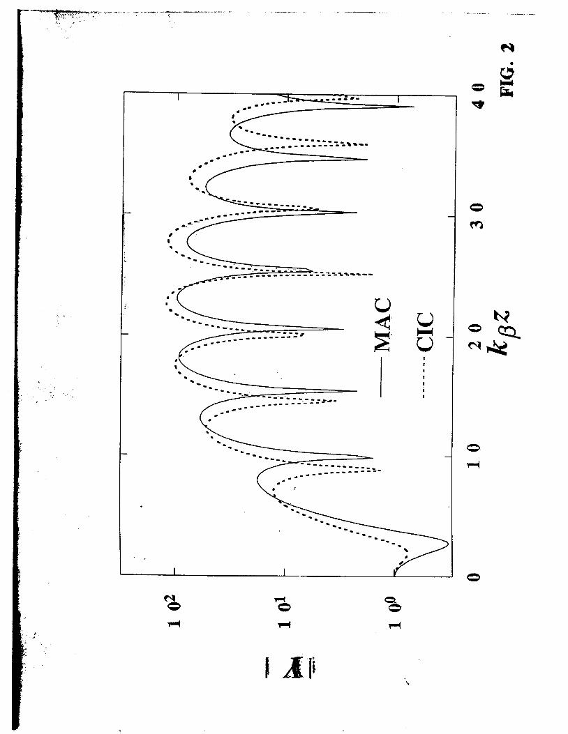
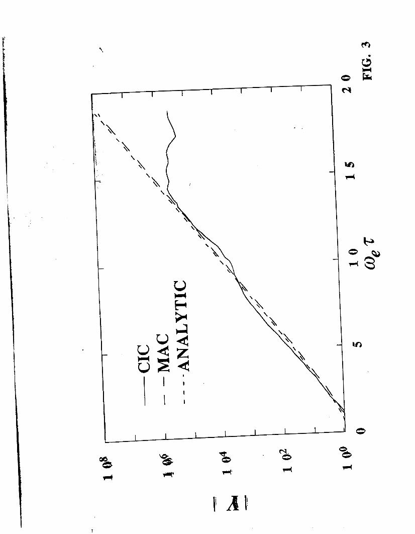
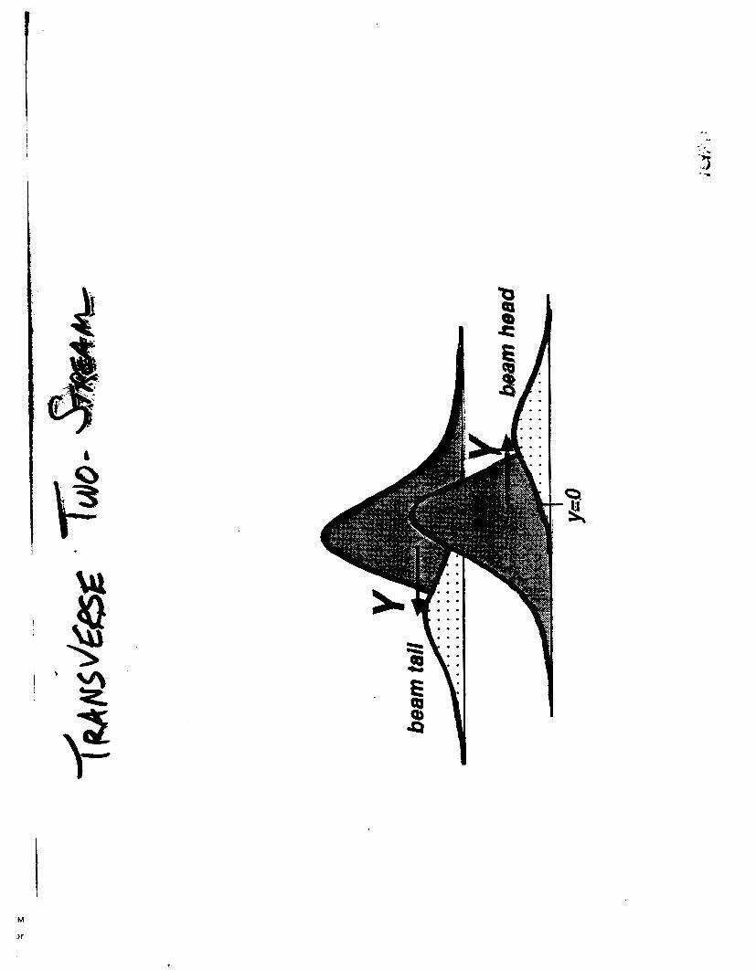
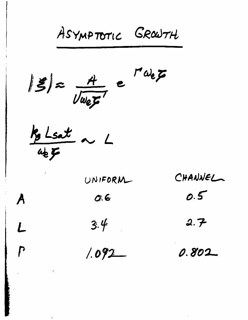
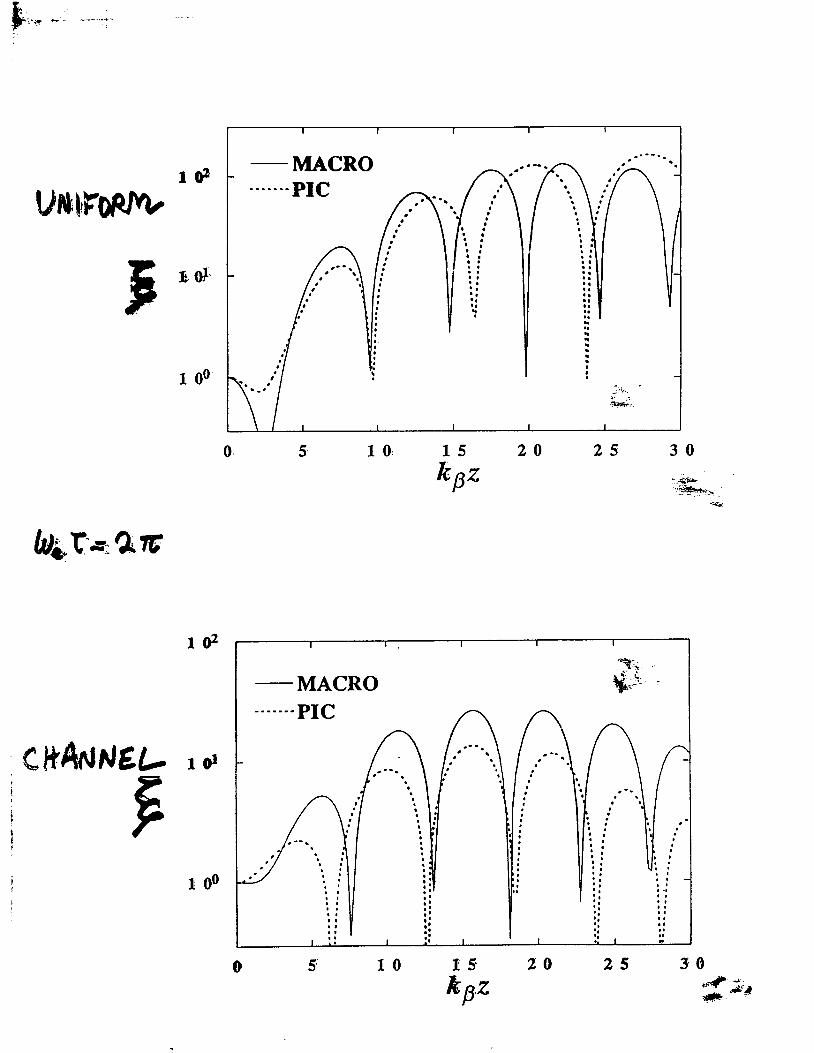
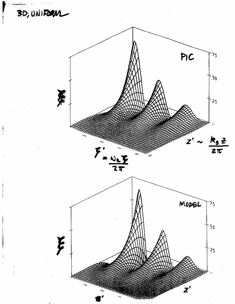
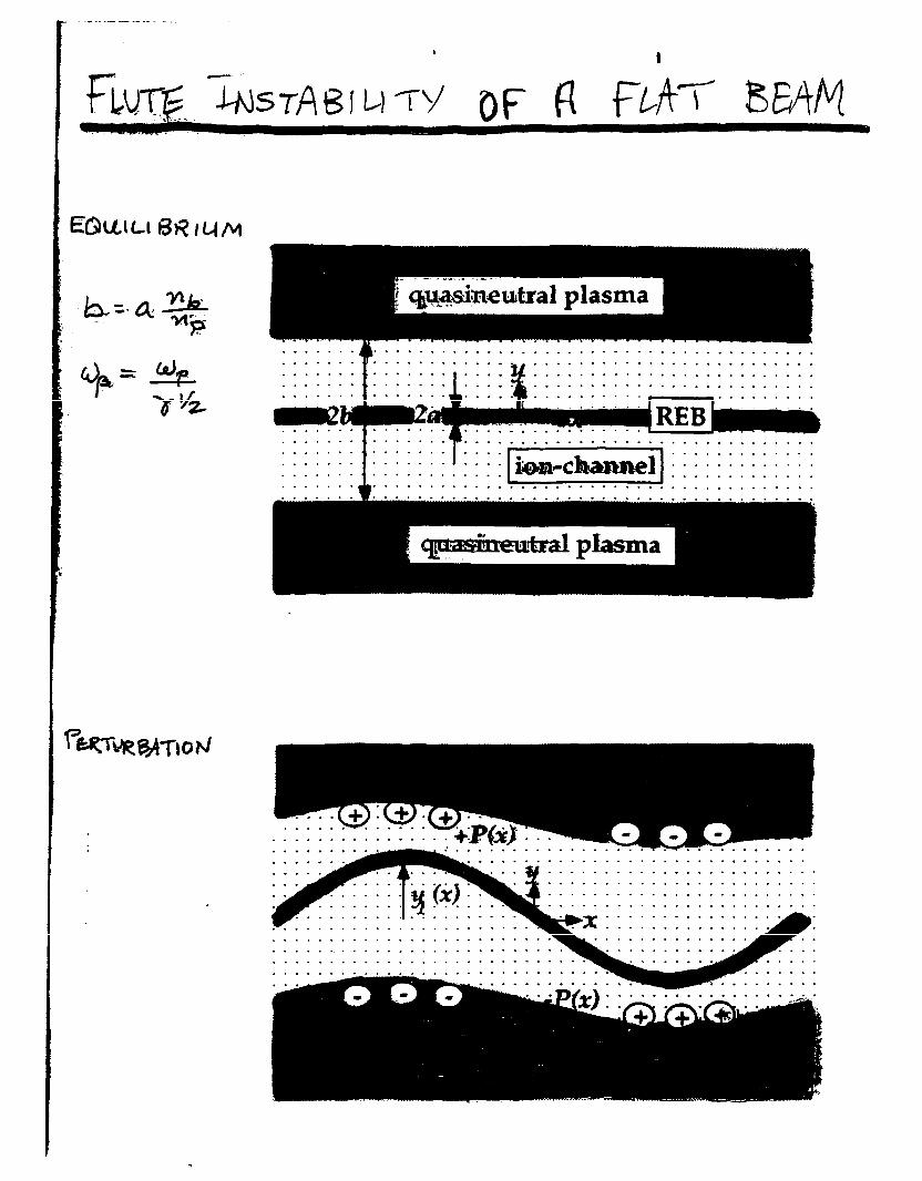
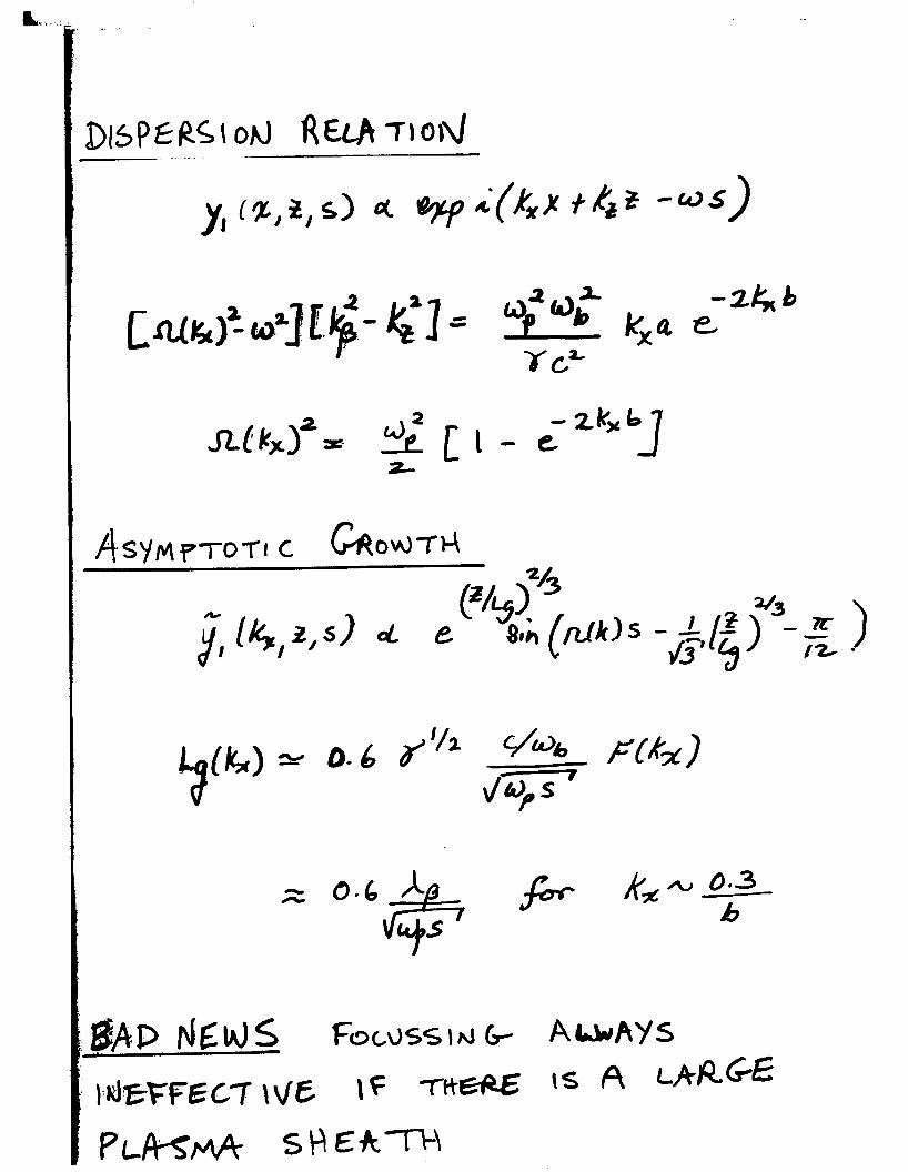
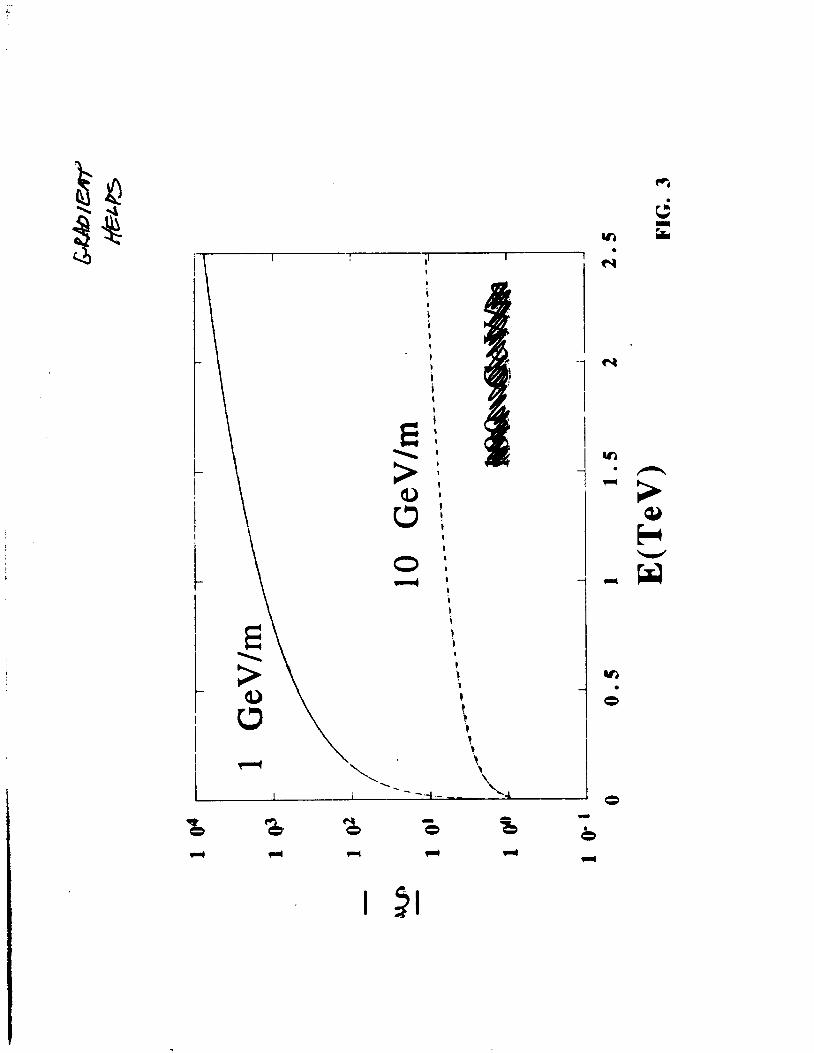
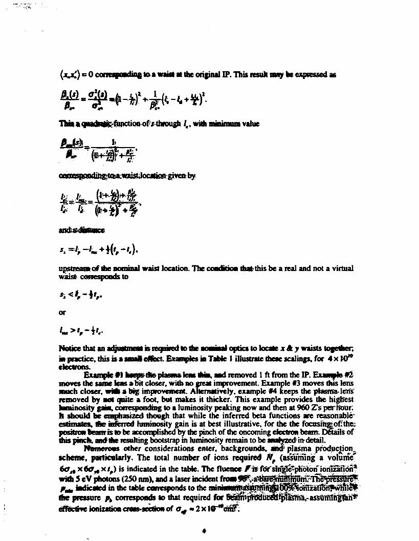
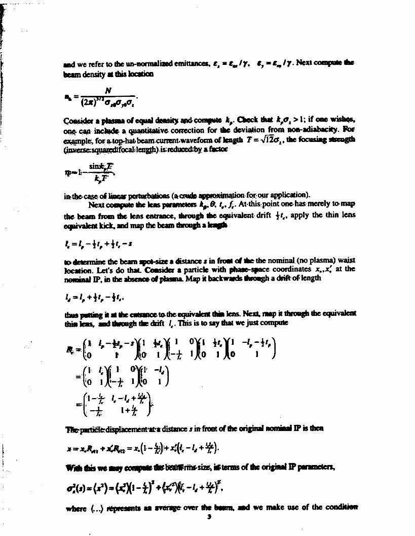


