www.tridonic.com 1 Subject to change without notice. Data sheet 10/16-LED270-4 LED light engine / OLED LED compact Product description • Ideal for ceiling-mounted and wallmounted luminaires • LED system solution consisting of the LED module, the control gear with integrated emergency function and SWITCH sensor • Based on circular and TC-DD fluorescent lamps • Efficacy of the module up to 147 lm/W • SO version is compatible with SWITCH Sensor HF 5BP • Integrated separate emergency LEDs controlled by EM powerLED • High colour rendering index CRI > 80 • Small colour tolerance MacAdam 3 3 • Small luminous flux tolerances • Colour temperatures 3,000 and 4,000 K • Push terminals for quick and simple wiring • Simple installation (e.g. screws) • Long life-time: 50,000 hours • 5-year guarantee • CLE 190: Round Shape enabling a bigger LED area for a better spread of light (by keeping the same position of mounting holes) È Standards, page 4 For colour temperatures and tolerances, page 7 Module CLE G2 190mm 1500lm ADV EM Modules CLE CLE G2 190mm 1500lm ADV EM CLE G2 190mm 1500lm ADV EM SO Typical application
Transcript
www.tridonic.com 1Subject to change without notice.
Data sheet 10/16-LED270-4
LED light engine / OLED
LED compact
Product description
• Ideal for ceiling-mounted and wallmounted luminaires
• LED system solution consisting of the LED module, the control
gear with integrated emergency function and SWITCH sensor
• Based on circular and TC-DD fluorescent lamps
• Efficacy of the module up to 147 lm/W
• SO version is compatible with SWITCH Sensor HF 5BP
• Integrated separate emergency LEDs controlled by
EM powerLED
• High colour rendering index CRI > 80
• Small colour tolerance MacAdam 33
• Small luminous flux tolerances
• Colour temperatures 3,000 and 4,000 K
• Push terminals for quick and simple wiring
• Simple installation (e.g. screws)
• Long life-time: 50,000 hours
• 5-year guarantee
• CLE 190: Round Shape enabling a bigger LED area for a better
spread of light (by keeping the same position of mounting holes)
ÈStandards, page 4
For colour temperatures and tolerances, page 7
Module CLE G2 190mm 1500lm ADV EM
Modules CLE
CLE G2 190mm 1500lm ADV EM
CLE G2 190mm 1500lm ADV EM SO
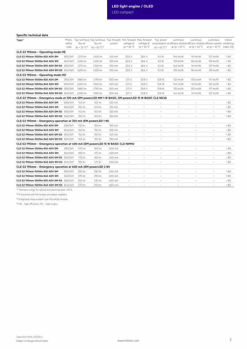
Typical application
www.tridonic.com 2Subject to change without notice.
Data sheet 10/16-LED270-4
LED light engine / OLED
LED compact
Technical dataBeam characteristic 120°
Ambient temperature range -25 ... +45 °C
tp rated 65 °C
tc 85 °C
Max. DC forward current 720 mA
Max. permissible LF current ripple 790 mA
Max. permissible peak current 960 mA / max. 10 ms
Max. permissible output voltage of LED Driver2 300 V
Insulation test voltage 1.6 kV
ESD classification severity level 4
Risk group (EN 62471:2008) 1
Type of protection IP00
Module CLE G2 190mm 1500lm ADV EM
Modules CLE
Ø4
48,5
48,585
85
Ø190
182
182
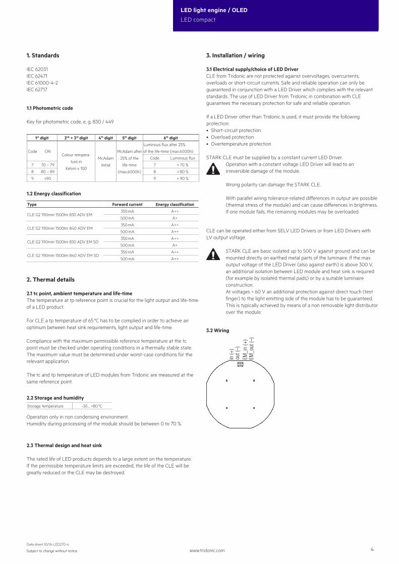
CLE G2 190mm 1500lm ADV EM
Ø4
48,5
48,585
(56,5) 69
85
Ø190
182
(61)
60
182
CLE G2 190mm 1500lm ADV EM SO
Ordering data
Type Article numberColour temperature
Packaging,carton
Weightper pc.
CLE G2 190mm 1500lm 830 ADV EM 89600437 3,000 K 50 pc(s). 0.075 kg
CLE G2 190mm 1500lm 840 ADV EM 89600570 4,000 K 50 pc(s). 0.075 kg
CLE G2 190mm 1500lm 830 ADV EM SO 89600571 3,000 K 50 pc(s). 0.065 kg
CLE G2 190mm 1500lm 840 ADV EM SO 89600572 4,000 K 50 pc(s). 0.065 kg
www.tridonic.com 3Subject to change without notice.
Data sheet 10/16-LED270-4
LED light engine / OLED
LED compact
Specific technical dataType4 Photo-
metric code
Typ. luminous flux at
tp = 25 °C1
Typ. luminous flux at
tp = 65 °C1
Typ. forward current
Min. forward voltage at tp = 65 °C
Max. forward voltage at tp = 25 °C
Typ. power consumption at
tp = 65 °C1
Luminous efficacy module
at tp = 25 °C
Luminous efficacy module
at tp = 65 °C
Luminous efficacy system
at tp = 65 °C
Colour rendering index CRI
CLE G2 190mm – Operating mode HECLE G2 190mm 1500lm 830 ADV EM 830/349 1,370 lm 1,300 lm 350 mA 25.0 V 28.4 V 9.2 W 146 lm/W 141 lm/W 127 lm/W > 80
CLE G2 190mm 1500lm 840 ADV EM 840/349 1,490 lm 1,420 lm 350 mA 25.0 V 28.4 V 9.2 W 159 lm/W 154 lm/W 139 lm/W > 80
CLE G2 190mm 1500lm 830 ADV EM SO 830/349 1,370 lm 1,300 lm 350 mA 25.0 V 28.4 V 9.2 W 146 lm/W 141 lm/W 127 lm/W > 80
CLE G2 190mm 1500lm 840 ADV EM SO 840/349 1,490 lm 1,420 lm 350 mA 25.0 V 28.4 V 9.2 W 159 lm/W 154 lm/W 139 lm/W > 80
CLE G2 190mm – Operating mode HOCLE G2 190mm 1500lm 830 ADV EM 830/349 1,880 lm 1,790 lm 500 mA 27.1 V 30.8 V 13.8 W 132 lm/W 130 lm/W 117 lm/W > 80
CLE G2 190mm 1500lm 840 ADV EM 840/349 2,050 lm 1,950 lm 500 mA 27.1 V 30.8 V 13.8 W 144 lm/W 141 lm/W 127 lm/W > 80
CLE G2 190mm 1500lm 830 ADV EM SO 830/349 1,880 lm 1,790 lm 500 mA 27.1 V 30.8 V 13.8 W 132 lm/W 130 lm/W 117 lm/W > 80
CLE G2 190mm 1500lm 840 ADV EM SO 840/349 2,050 lm 1,950 lm 500 mA 27.1 V 30.8 V 13.8 W 144 lm/W 141 lm/W 127 lm/W > 80
CLE G2 190mm – Emergency mode at 320 mA (EM powerLED NM 1 W BASIC, EM powerLED 15 W BASIC CLE NiCd)CLE G2 190mm 1500lm 830 ADV EM 830/349 145 lm 140 lm 320 mA – – – – – – > 80
CLE G2 190mm 1500lm 830 ADV EM SO 830/349 250 lm 230 lm 600 mA – – – – – – > 80
CLE G2 190mm 1500lm 840 ADV EM SO 840/349 270 lm 255 lm 600 mA – – – – – – > 80
1 Tolerance range for optical and electrical data: ±10 %.
2 If mounted with M4 screws and plastic washers.
3 Integrated measurement over the whole module.
4 HE ... high efficiency, HO ... high output.
www.tridonic.com 4Subject to change without notice.
Data sheet 10/16-LED270-4
LED light engine / OLED
LED compact
1. Standards
IEC 62031IEC 62471IEC 61000-4-2IEC 62717
1.2 Energy classification
Type Forward current Energy classification
CLE G2 190mm 1500lm 830 ADV EM350 mA A++
500 mA A+
CLE G2 190mm 1500lm 840 ADV EM350 mA A++
500 mA A++
CLE G2 190mm 1500lm 830 ADV EM SO350 mA A++
500 mA A+
CLE G2 190mm 1500lm 840 ADV EM SO350 mA A++
500 mA A++
2. Thermal details
2.1 tc point, ambient temperature and life-timeThe temperature at tp reference point is crucial for the light output and life-time of a LED product.
For CLE a tp temperature of 65 °C has to be complied in order to achieve an optimum between heat sink requirements, light output and life-time.
Compliance with the maximum permissible reference temperature at the tc point must be checked under operating conditions in a thermally stable state. The maximum value must be determined under worst-case conditions for the relevant application.
The tc and tp temperature of LED modules from Tridonic are measured at the same reference point.
2.2 Storage and humidityStorage temperature -30 ... +80 °C
Operation only in non condensing environment.Humidity during processing of the module should be between 0 to 70 %.
3. Installation / wiring
3.1 Electrical supply/choice of LED DriverCLE from Tridonic are not protected against overvoltages, overcurrents, overloads or short-circuit currents. Safe and reliable operation can only be guaranteed in conjunction with a LED Driver which complies with the relevant standards. The use of LED Driver from Tridonic in combination with CLE guarantees the necessary protection for safe and reliable operation.
If a LED Driver other than Tridonic is used, it must provide the following protection:• Short-circuit protection• Overload protection• Overtemperature protection
STARK CLE must be supplied by a constant current LED Driver.Operation with a constant voltage LED Driver will lead to an irreversible damage of the module.
Wrong polarity can damage the STARK CLE.
With parallel wiring tolerance-related differences in output are possible(thermal stress of the module) and can cause differences in brightness.If one module fails, the remaining modules may be overloaded.
CLE can be operated either from SELV LED Drivers or from LED Drivers with LV output voltage.
STARK CLE are basic isolated up to 500 V against ground and can be mounted directly on earthed metal parts of the luminaire. If the max. output voltage of the LED Driver (also against earth) is above 300 V, an additional isolation between LED module and heat sink is required (for example by isolated thermal pads) or by a suitable luminaire construction.At voltages > 60 V an additional protection against direct touch (test finger) to the light emitting side of the module has to be guaranteed. This is typically achieved by means of a non removable light distributor over the module.
3.2 Wiring
out (
–)in
(+)
EM_i
n (+
)EM
_out
(–)
2.3 Thermal design and heat sink
The rated life of LED products depends to a large extent on the temperature. If the permissible temperature limits are exceeded, the life of the CLE will be greatly reduced or the CLE may be destroyed.
350 mA 65 °C 30,000 h >50,000 h >50,000 h >50,000 h >50,000 h >50,000 h
500 mA 65 °C 24,000 h >50,000 h >50,000 h >50,000 h >50,000 h >50,000 h
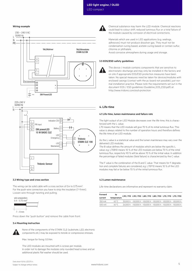
Wiring example
UmodulesSTARK CLE EM
LN
230 – 240 V AC50/60 Hz
Udriver
EM PowerLED
Permanentline
PE
+–
Akku
+–
EM powerLED 15 W BASIC CLE
220–240 V
LN
50/60 Hz
L
N
LEDMaintained
LEDEmergency
+–
EMEM
–+
–+
+–
Battery
Indication LED
+–
OP
PIR input
Tridonic Sensor
Tridonic STARK CLE 190
LN
L´
��
SL
CF
3.3 Wiring type and cross section
The wiring can be solid cable with a cross section of 0.4 to 0.75 mm². For the push-wire connection you have to strip the insulation (7–9 mm).Loosen wire through twisting and pulling.
7 – 9 mm
wire preparation:0.4 – 0.75 mm²
Press down the “push button” and remove the cable from front.
3.4 Mounting instruction
None of the components of the STARK CLE (substrate, LED, electronic components etc.) may be exposed to tensile or compressive stresses.
Max. torque for fixing: 0.5 Nm.
The LED modules are mounted with 4 screws per module.In order not to damage the modules only rounded head screws and anadditional plastic flat washer should be used.
Chemical substance may harm the LED module. Chemical reactions could lead to colour shift, reduced luminous flux or a total failure of the module caused by corrosion of electrical connections.
Materials which are used in LED applications (e.g. sealings, adhesives) must not produce dissolver gas. They must not be condensation curing based, acetate curing based or contain sulfur, chlorine or phthalate.Avoid corrosive atmosphere during usage and storage.
3.5 EOS/ESD safety guidelines
The device / module contains components that are sensitive to electrostatic discharge and may only be installed in the factory and on site if appropriate EOS/ESD protection measures have been taken. No special measures need be taken for devices/modules with enclosed casings (contact with the pc board not possible), just nor-mal installation practice. Please note the requirements set out in the document EOS / ESD guidelines (Guideline_EOS_ESD.pdf) at: http://www.tridonic.com/esd-protection
4.1 Life-time, lumen maintenance and failure rate
The light output of an LED Module decreases over the life-time, this is charac-terized with the L value.L70 means that the LED module will give 70 % of its initial luminous flux. This value is always related to the number of operation hours and therefore defines the life-time of an LED module.
As the L value is a statistical value and the lumen maintenace may vary over the delivered LED modules.The B value defines the amount of modules which are below the specific L value, e.g. L70B10 means 10 % of the LED modules are below 70 % of the inital luminous flux, respectivly 90 % will be above 70 % of the initial value. In addition the percentage of failed modules (fatal failure) is characterized by the C value.
The F value is the combination of the B and C value. That means for F degrada-tion and complete failures are considered, e.g. L70F10 means 10 % of the LED modules may fail or be below 70 % of the initial luminous flux.
4.2 Lumen maintenance
4. Life-time
Life-time declarations are informative and represent no warranty claim.
www.tridonic.com 6Subject to change without notice.
Data sheet 10/16-LED270-4
LED light engine / OLED
LED compact
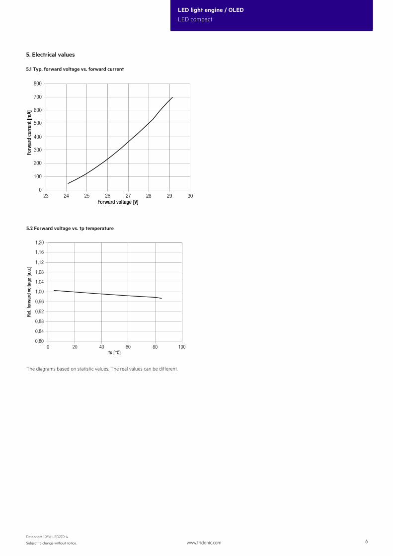
24 25 272623 28 29 300
100
200
800
500
600
700
400
300
Forward voltage [V]
Forw
ard
curr
ent [
mA]
0,80
1,20
1,00
1,08
1,04
1,12
1,16
20 40 600 80 100
0,92
0,96
0,84
0,88
tc [°C]
Rel.
forw
ard
volta
ge [a
.u.]
The diagrams based on statistic values. The real values can be different.
5. Electrical values
5.1 Typ. forward voltage vs. forward current
5.2 Forward voltage vs. tp temperature
www.tridonic.com 7Subject to change without notice.
Data sheet 10/16-LED270-4
LED light engine / OLED
LED compact
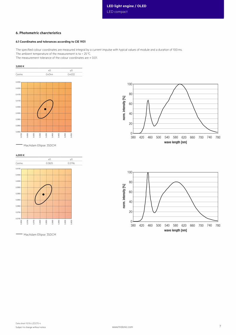
6. Photometric charcteristics
6.1 Coordinates and tolerances according to CIE 1931
The specified colour coordinates are measured integral by a current impulse with typical values of module and a duration of 100 ms.The ambient temperature of the measurement is ta = 25 °C.The measurement tolerance of the colour coordinates are ± 0.01.
3,000 K
x0 y0
Centre 0.4344 0.4032
380 420 460 500 540 580 620 660 700 740 7800
20
40
60
80
100
wave length [nm]
norm
. int
ensi
ty [%
]
380 420 460 500 540 580 620 660 700 740 7800
20
40
60
80
100
wave length [nm]
norm
. int
ensi
ty [%
]
4,000 K
x0 y0
Centre 0.3825 0.3796
MacAdam Ellipse: 3SDCM
MacAdam Ellipse: 3SDCM
0,3700
0,3750
0,3800
0,3850
0,3900
0,3950
0,4000
0,4050
0,4100
0,36
50
0,37
00
0,37
50
0,38
00
0,38
50
0,39
00
0,39
50
0,40
00
0,40
50
0,3850
0,3900
0,3950
0,4000
0,4050
0,4100
0,4150
0,4200
0,4250
0,41
50
0,42
00
0,42
50
0,43
00
0,43
50
0,44
00
0,44
50
0,45
00
0,45
50
www.tridonic.com 8Subject to change without notice.
Data sheet 10/16-LED270-4
LED light engine / OLED
LED compact
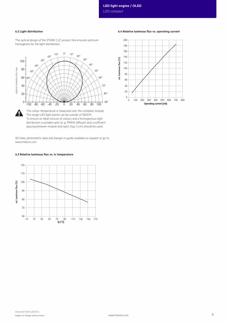
The optical design of the STARK CLE product line ensures optimumhomogenity for the light distribution.
rela
tive
inte
nsity
Iv/Iv
, max
3D-Data, photometric data and Design-in guide available on request or go to www.tridonic.com
The colour temperature is measured over the complete module. The single LED light points can be outside of 3SDCM. To ensure an ideal mixture of colours and a homogenious light distribution a suitable optic (e. g. PMMA diffuser) and a sufficient spacing between module and optic (typ. 5 cm) should be used.