28
LED Light Show LED Light Show Critical Design Review Critical Design Review Team Lit Michael Hatt Scott Butler Kristin Haeusler Brock Smith
| Date post: | 21-Dec-2015 |
| Category: |
Documents |
| View: | 213 times |
| Download: | 0 times |

LED Light ShowLED Light ShowCritical Design ReviewCritical Design Review
Team LitMichael Hatt
Scott Butler
Kristin Haeusler
Brock Smith
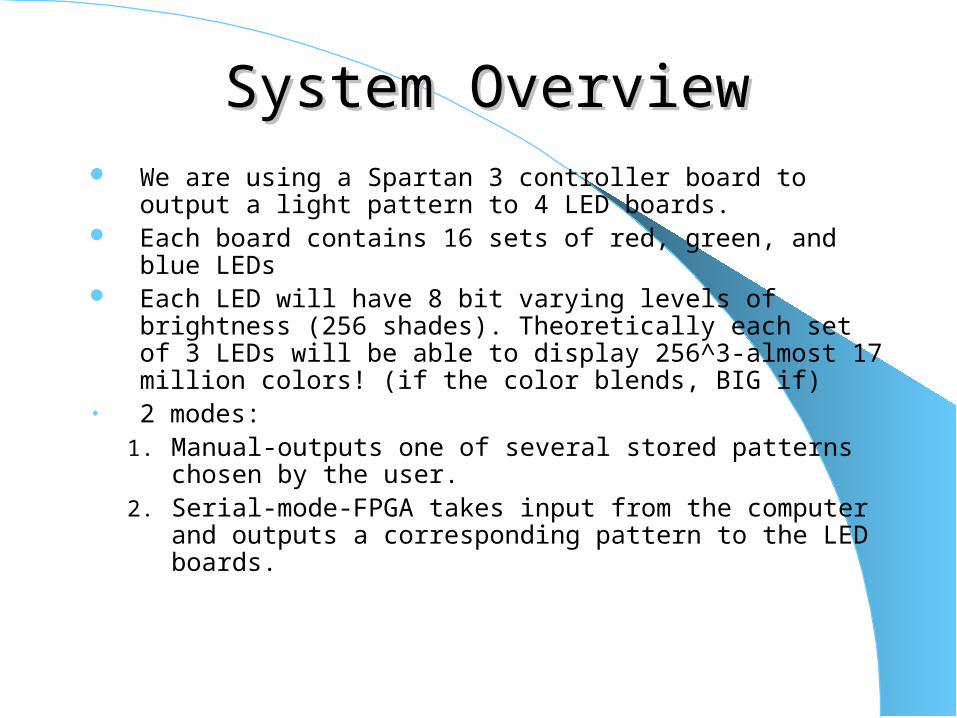
System OverviewSystem Overview We are using a Spartan 3 controller board to output a light
pattern to 4 LED boards. Each board contains 16 sets of red, green, and blue LEDs Each LED will have 8 bit varying levels of brightness (256
shades). Theoretically each set of 3 LEDs will be able to display 256^3-almost 17 million colors! (if the color blends, BIG if)
• 2 modes:1. Manual-outputs one of several stored patterns chosen by
the user.2. Serial-mode-FPGA takes input from the computer and
outputs a corresponding pattern to the LED boards.
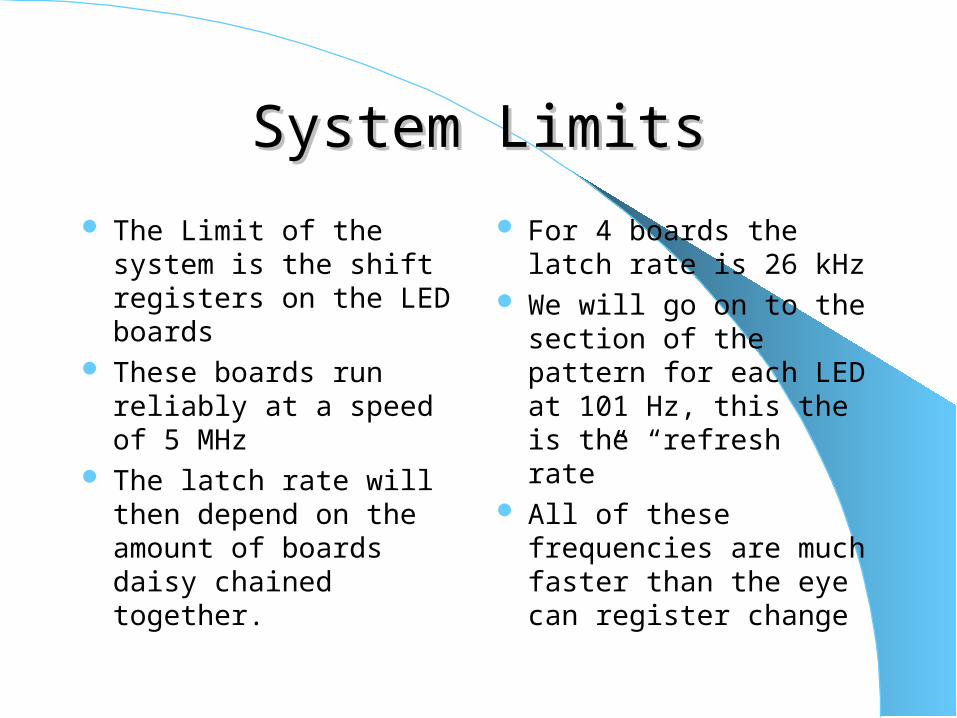
System LimitsSystem Limits
The Limit of the system is the shift registers on the LED boards
These boards run reliably at a speed of 5 MHz
The latch rate will then depend on the amount of boards daisy chained together.
For 4 boards the latch rate is 26 kHz
We will go on to the section of the pattern for each LED at 101 Hz, this the is the “refresh rate”
All of these frequencies are much faster than the eye can register change
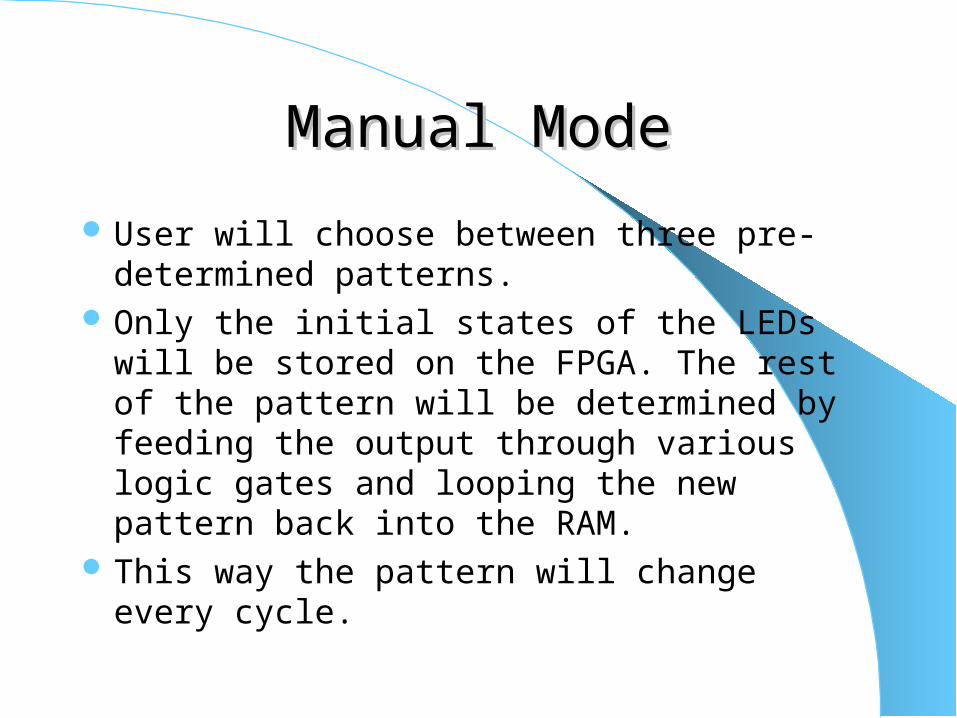
Manual ModeManual Mode
User will choose between three pre-determined patterns.
Only the initial states of the LEDs will be stored on the FPGA. The rest of the pattern will be determined by feeding the output through various logic gates and looping the new pattern back into the RAM.
This way the pattern will change every cycle.
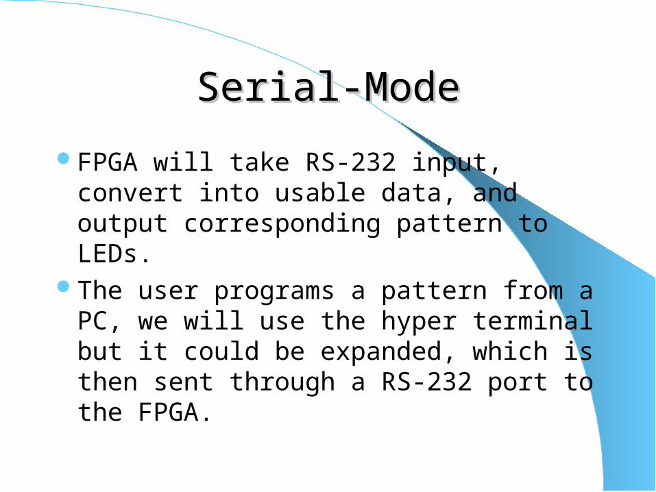
Serial-ModeSerial-Mode
FPGA will take RS-232 input, convert into usable data, and output corresponding pattern to LEDs.
The user programs a pattern from a PC, we will use the hyper terminal but it could be expanded, which is then sent through a RS-232 port to the FPGA.
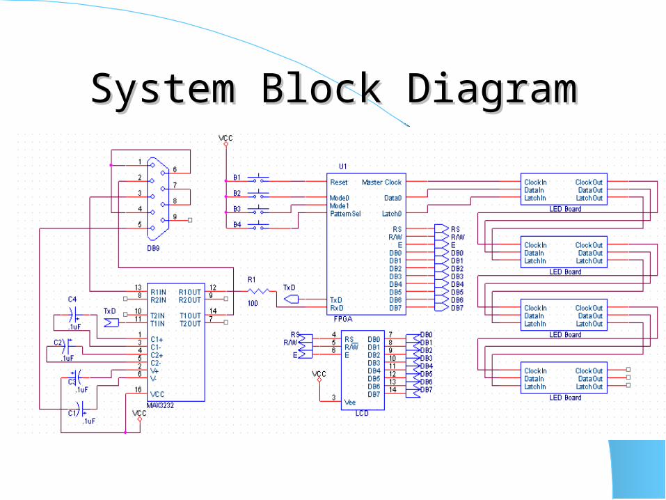
System Block DiagramSystem Block Diagram
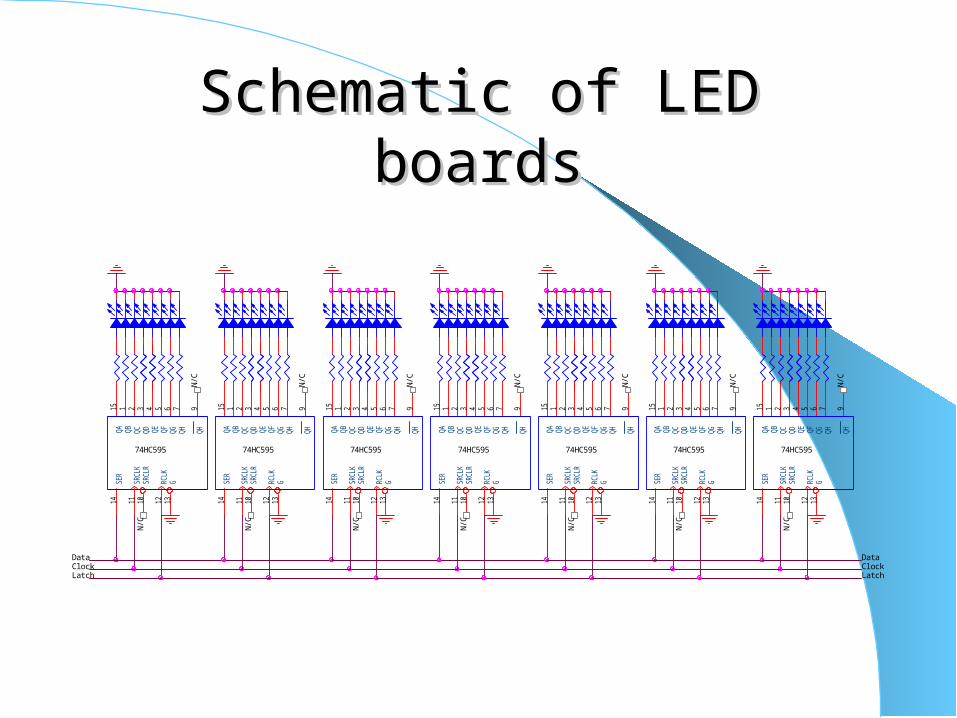
Schematic of LED boardsSchematic of LED boards
SER
14
SRCL
K11
SRCL
R10
RCLK
12
G13
QA15
QB1
QC2
QD3
QE4
QF5
QG6
QH7
QH9
SER
14
SRCL
K11
SRCL
R10
RCLK
12
G13
QA15
QB1
QC2
QD3
QE4
QF5
QG6
QH7
QH9
SER
14
SRCL
K11
SRCL
R10
RCLK
12
G13
QA15
QB1
QC2
QD3
QE4
QF5
QG6
QH7
QH9
SER
14
SRCL
K11
SRCL
R10
RCLK
12
G13
QA15
QB1
QC2
QD3
QE4
QF5
QG6
QH7
QH9
SER
14
SRCL
K11
SRCL
R10
RCLK
12
G13
QA15
QB1
QC2
QD3
QE4
QF5
QG6
QH7
QH9
SER
14
SRCL
K11
SRCL
R10
RCLK
12
G13
QA15
QB1
QC2
QD3
QE4
QF5
QG6
QH7
QH9
SER
14
SRCL
K11
SRCL
R10
RCLK
12
G13
QA15
QB1
QC2
QD3
QE4
QF5
QG6
QH7
QH9
74HC59574HC59574HC595 74HC59574HC59574HC59574HC595
N/C
N/C
N/C
Data
N/C
N/C
N/C
N/C
Latch Latch
DataClock
N/C
Clock
N/C
N/C
N/C
N/C
N/C
N/C
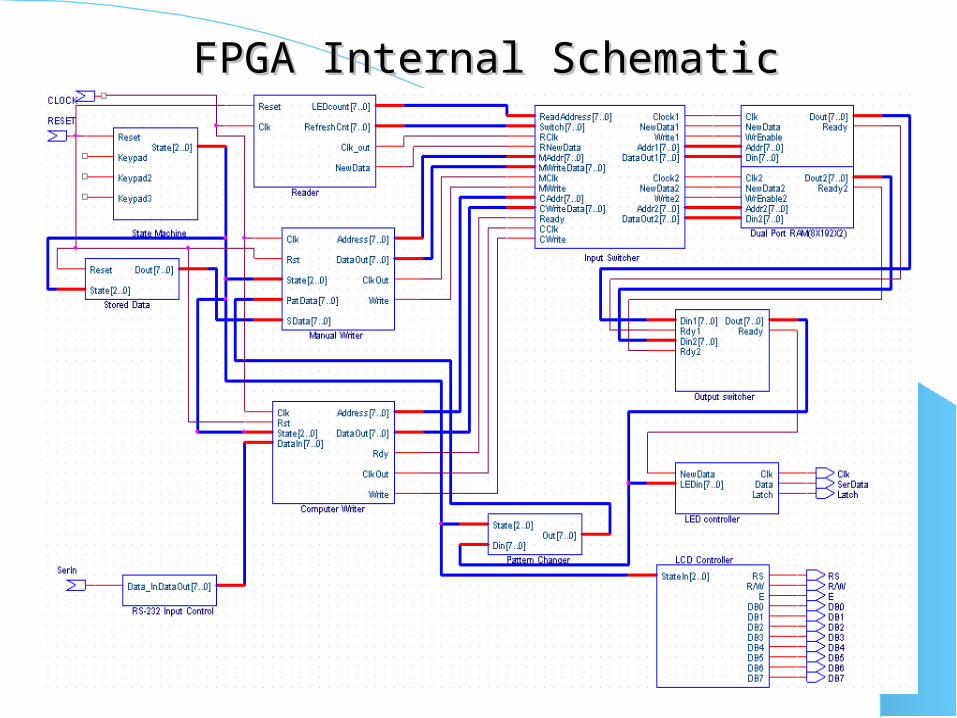
FPGA Internal SchematicFPGA Internal Schematic
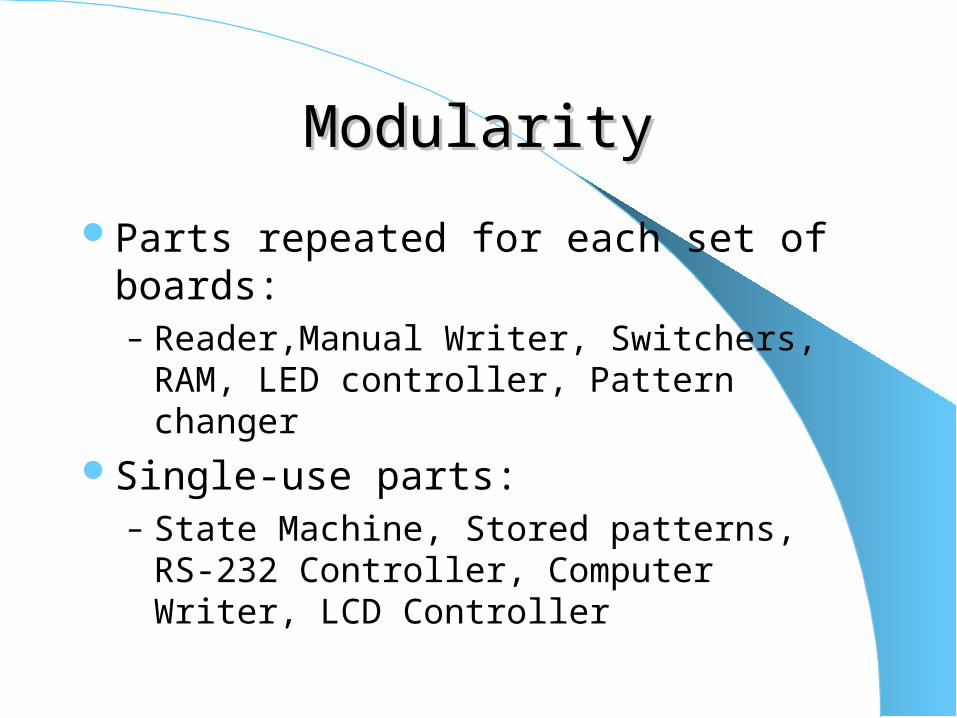
ModularityModularity
Parts repeated for each set of boards:– Reader,Manual Writer, Switchers, RAM, LED
controller, Pattern changer
Single-use parts: – State Machine, Stored patterns, RS-232
Controller, Computer Writer, LCD Controller
State MachineState Machine
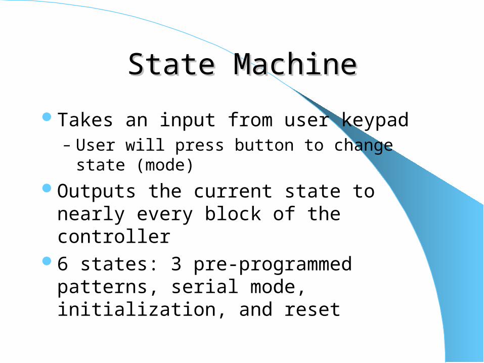
Takes an input from user keypad– User will press button to change state (mode)
Outputs the current state to nearly every block of the controller
6 states: 3 pre-programmed patterns, serial mode, initialization, and reset
LCD controllerLCD controller
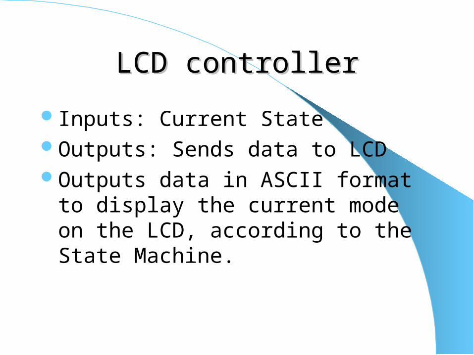
Inputs: Current StateOutputs: Sends data to LCDOutputs data in ASCII format to display the
current mode on the LCD, according to the State Machine.
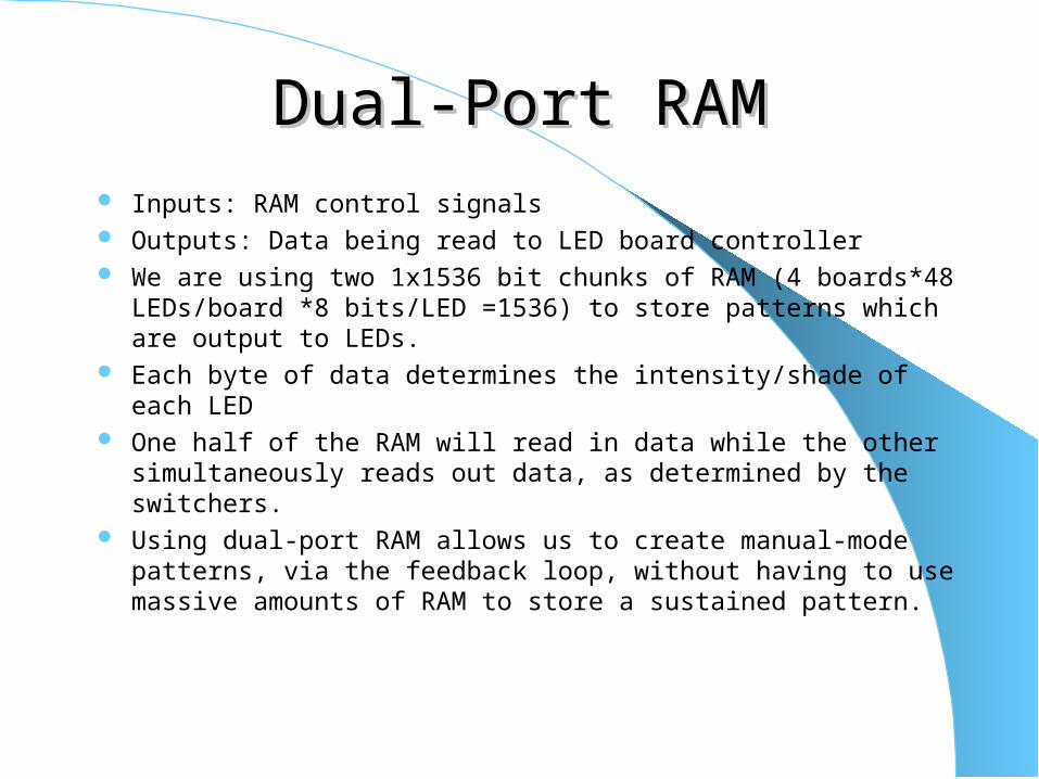
Dual-Port RAMDual-Port RAM Inputs: RAM control signals Outputs: Data being read to LED board controller We are using two 1x1536 bit chunks of RAM (4 boards*48
LEDs/board *8 bits/LED =1536) to store patterns which are output to LEDs.
Each byte of data determines the intensity/shade of each LED One half of the RAM will read in data while the other simultaneously
reads out data, as determined by the switchers. Using dual-port RAM allows us to create manual-mode patterns, via
the feedback loop, without having to use massive amounts of RAM to store a sustained pattern.

LED controllerLED controller Inputs: Pattern data from RAM Outputs: Clock, Serial data and latch signal Takes the data from RAM. Determines if LED should get a high or low and then shifts
out the correct bit. After shifting 192 bits it triggers a latch to display the
pattern After 256 cycles it moves to the set of data The LED value determines the fraction of the 256 cycles
that the LED will be turned on, so as to give the appropriate shade
Data ReaderData Reader
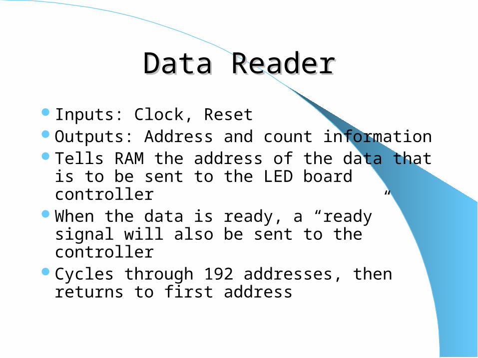
Inputs: Clock, ResetOutputs: Address and count informationTells RAM the address of the data that is to
be sent to the LED board controllerWhen the data is ready, a “ready” signal
will also be sent to the controllerCycles through 192 addresses, then returns
to first address
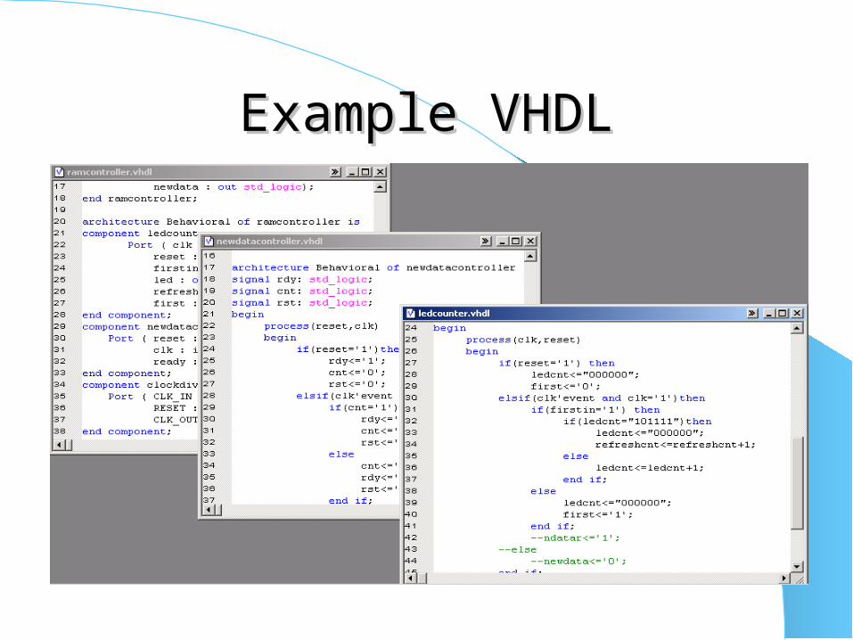
Example VHDLExample VHDL
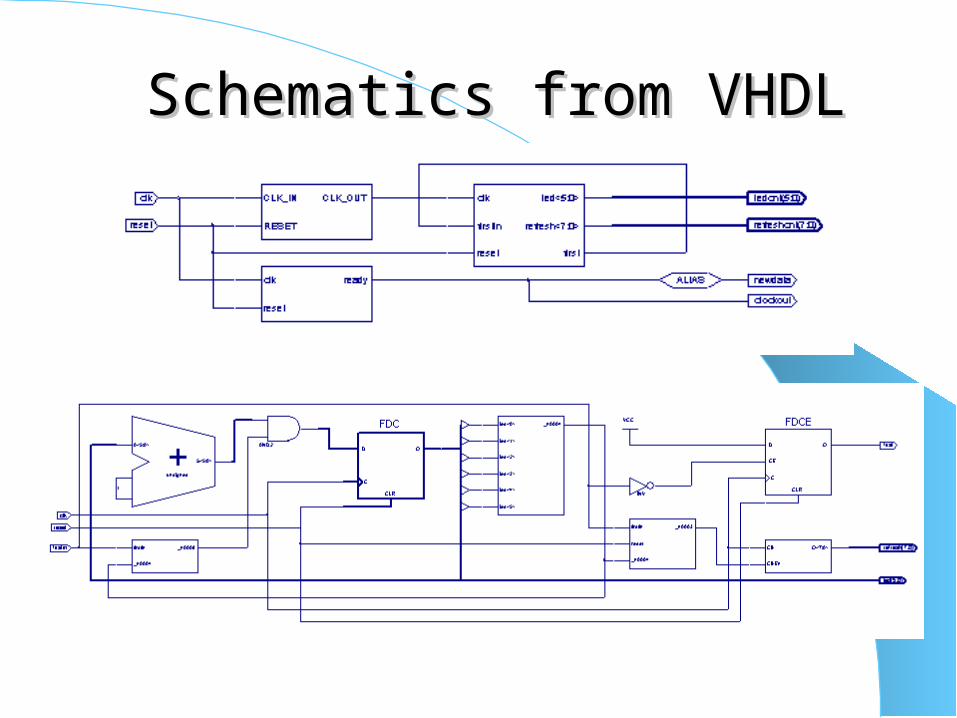
Schematics from VHDLSchematics from VHDL
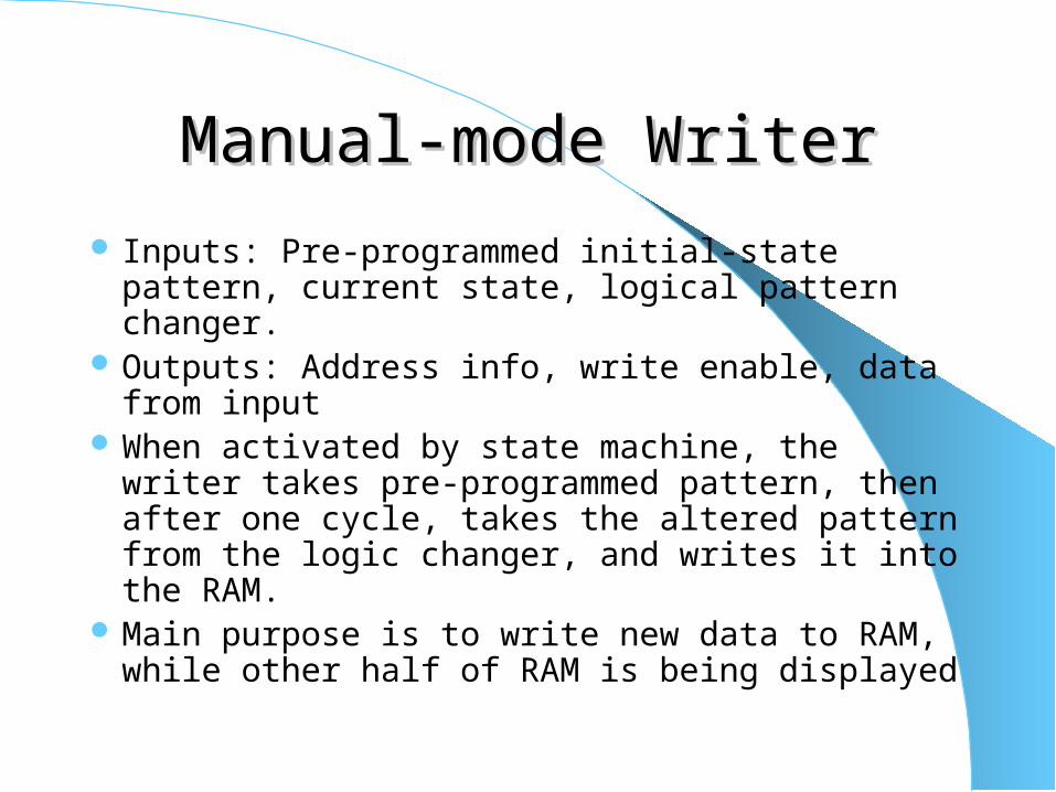
Manual-mode WriterManual-mode Writer
Inputs: Pre-programmed initial-state pattern, current state, logical pattern changer.
Outputs: Address info, write enable, data from input
When activated by state machine, the writer takes pre-programmed pattern, then after one cycle, takes the altered pattern from the logic changer, and writes it into the RAM.
Main purpose is to write new data to RAM, while other half of RAM is being displayed
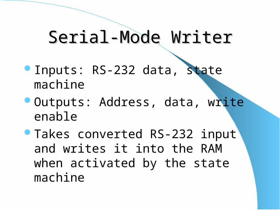
Serial-Mode WriterSerial-Mode Writer
Inputs: RS-232 data, state machineOutputs: Address, data, write enableTakes converted RS-232 input and writes it
into the RAM when activated by the state machine

RAM Input SwitcherRAM Input Switcher
Inputs: Data reader outputs, manual and serial-mode writer outputs
Outputs to RAMRoutes all data and signals to the
appropriate half of the RAMContinuously switches between the two
halves of the RAM at the correct time
RAM output switcherRAM output switcher
Inputs: Outputs of RAM Outputs: Data and control signals being read to
LED controller Takes output data from RAM and outputs data
from one of the two halves of RAM, in an alternating manner.
Synchronous with the input switcher to assure that one chunk of RAM is reading in data while the other chunk is outputting data.
Stored DataStored Data
No inputsOutputs: Data to be written to RAMStores initial data patterns for first cycle of
manual modeOnly stores 4*48 bytes of dataThe entire duration of the pattern is
determined by this initial data
Pattern ChangerPattern Changer
Inputs: Current State, Data being read to LED controller
Outputs: Changed dataTakes each byte being read out and changes
it using pre-determined logic circuitryPrepares altered data for next cycle as
previous data is being read out
RS-232 controllerRS-232 controller
Inputs: Data from RS-232 portOutputs: Data(in bytes)Communicates with the RS-232 port to
gather data from the computer.Converts the input data to a form that is
ready to be written into RAM.
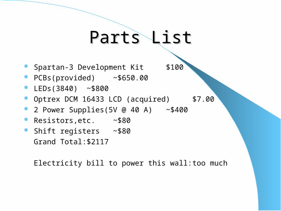
Parts ListParts List
Spartan-3 Development Kit $100 PCBs(provided) ~$650.00 LEDs(3840) ~$800 Optrex DCM 16433 LCD (acquired) $7.00 2 Power Supplies(5V @ 40 A) ~$400 Resistors,etc. ~$80 Shift registers ~$80
Grand Total: $2117
Electricity bill to power this wall: too much
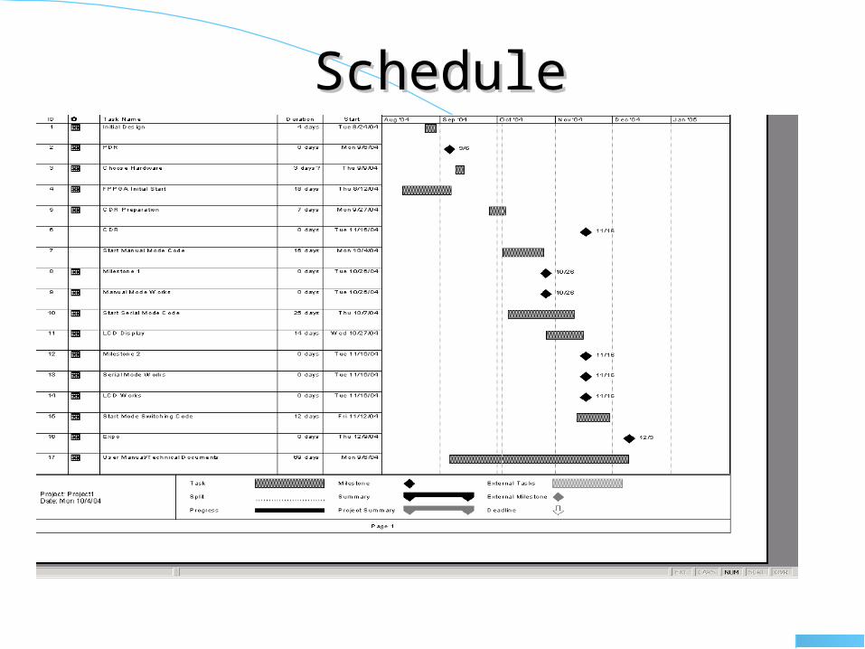
ScheduleSchedule
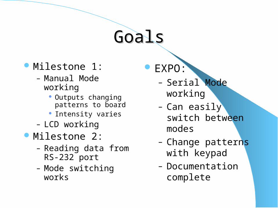
GoalsGoals
Milestone 1:– Manual Mode working
Outputs changing patterns to board
Intensity varies
– LCD working Milestone 2:
– Reading data from RS-232 port
– Mode switching works
EXPO:– Serial Mode working– Can easily switch
between modes– Change patterns with
keypad– Documentation
complete
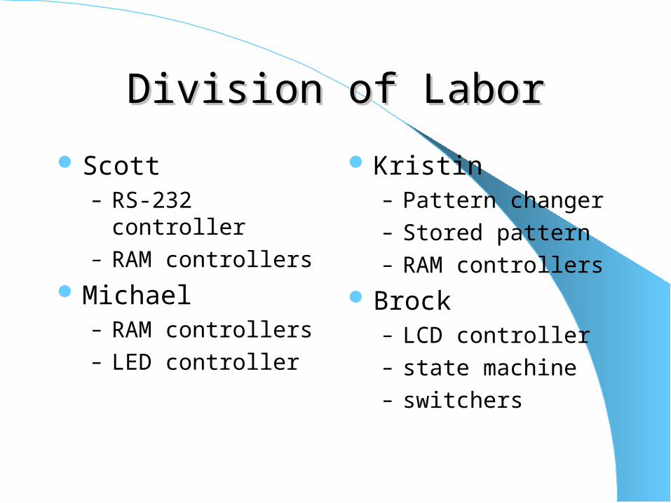
Division of LaborDivision of Labor
Scott– RS-232 controller– RAM controllers
Michael– RAM controllers– LED controller
Kristin– Pattern changer– Stored pattern– RAM controllers
Brock– LCD controller– state machine– switchers

??


