Page 1
NAMTS PUMP REPAIR TECHNICIAN TRAINEE GUIDE V-652-4222
PROCESS 131.10-2 Sheet 1 of 24
FOR TRAINING USE ONLY
INFORMATION SHEET 131.10-2
MECHANICAL SEALS (IDENTIFICATION, INSTALLATION, TROUBLESHOOTING)
A. INTRODUCTION
This lesson is an introduction to mechanical seals, to include their identification, installation,
and troubleshooting. Mechanical seals are used throughout the Navy in many types of
pumps; an understanding of them is necessary to ensure proper maintenance and longevity of
affected equipment. Each term and definition is utilized throughout the training material.
B. REFERENCES
1. Naval Sea Systems Command (NAVSEA) S9086-RH-STM-010, Naval Ships’ Technical
Manual (NSTM) 503, Pumps
2. NAVEDTRA 14104A, Fireman
3. NAVEDTRA 14075A, Engineman
4. NAVEDTRA 14150A, Machinist’s Mate (Surface)
5. NAVEDTRA 14113, Gas Turbine Systems Technician, Vol. 1
6. NAVSEA S9086-S4-STM-010, NSTM 556, Hydraulic Equipment (Power Transmission
and Control)
7. NAVSEA DRAWING 7307417, A General Procedures for Overhaul, Alignment, and
Testing of Surface Ship Pumps
C. INFORMATION
1. Introduction.
a. Mechanical seals are used throughout the Navy in many types of pumps; an
understanding of them is necessary to ensure proper maintenance and longevity of
affected equipment. Each concept introduced is utilized throughout the training
material.
2. Safety precautions.
a. Specific warnings, cautions and notes regarding the system and equipment appear
throughout the technical manuals following paragraph headings and immediately
preceding the text to which they apply.
1) Warning - Used to draw special attention to potential hazardous situations which
if not avoided could result in minor personal injury, serious injury, or death.
2) Caution - Used to draw special attention to anything that could damage equipment
or cause the loss of data and includes what could happen if the caution is ignored.
3) Note - Used to highlight essential procedure(s) by visually distinguishing it from
the rest of the text and can contain any type of information except safety
information.
Page 2
NAMTS PUMP REPAIR TECHNICIAN TRAINEE GUIDE V-652-4222
PROCESS 131.10-2 Sheet 2 of 24
FOR TRAINING USE ONLY
3. Terminology.
a. Mechanical seal terms.
1) Mechanical seal: A mechanical device located in the pump stuffing box, as shown
in Figure 131.10-2.1, consisting of a stationary element and a rotating element,
each with a smooth, flat sealing face that prevents the flow of liquid or gas into or
out of the pump casing.
Figure 131.10-2.1: Mechanical Seal Location (Typical)
Page 3
NAMTS PUMP REPAIR TECHNICIAN TRAINEE GUIDE V-652-4222
PROCESS 131.10-2 Sheet 3 of 24
FOR TRAINING USE ONLY
2) Shaft sleeve: A cylindrical piece fitted over the shaft to protect the shaft through
the stuffing box and which may also serve to locate the impeller on the shaft, as
shown in Figure 131.10-2.1.
3) Backup stuffing box: Recessed portion of the gland and cover of a mechanical
seal subassembly designed to accommodate two or more rings of packing.
4) Bellows: Spring portion of a mechanical seal that forms a flexible secondary
sealing assembly which joins the primary sealing face to the shaft, as shown in
Figure 131.10-2.2.
Figure 131.10-2.2: Mechanical Seals (Typical)
5) Seal gland: Retains the stationary element of a mechanical seal, as shown in
Figure 131.10-2.2.
6) Non-pusher seal: The portion of a mechanical seal’s secondary seal which
maintains the seal by accounting for any axial motion of the primary seal by the
expansion or contraction of a bellows type arrangement. These seals are usually
elastomeric bellows, corrugated metal bellows, or welded metal bellows.
7) Primary seal: Mechanical seal interface oriented perpendicular to the shaft, made
up of the primary seal ring and mating ring, as shown in Figure 131.10-2.2.
8) Primary seal ring: Precision lapped seal face in the seal assembly; can be rotating
or stationary based on the design, as shown in Figure 131.10-2.2.
9) Pusher seal: The portion of a mechanical seal’s secondary seal which is dynamic
in nature and moves axially on the shaft to account for any axial movement of the
primary seal due to sealing face irregularities, as shown in Figure 131.10-2.2.
These seals are generally O-rings, Anti-X-rings, chevrons rings, etc.
Page 4
NAMTS PUMP REPAIR TECHNICIAN TRAINEE GUIDE V-652-4222
PROCESS 131.10-2 Sheet 4 of 24
FOR TRAINING USE ONLY
10) Semi-split mechanical seal: A mechanical seal where only the mating ring,
primary ring and elastomers are split in half.
11) Full-split mechanical seal: A mechanical seal where all components of the seal are
split in half.
12) Seal chamber: Term used in place of “stuffing box” when a mechanical seal is
used vice packing material.
13) Secondary seal: The portion of the mechanical seal which prevents the escape of
the pumped fluid or ingress of air at the points where the mechanical seal is
connected to the shaft and the casing.
b. Packing terms.
1) Gland: A follower which compresses packing in a stuffing box, as shown in
Figure 131.10-2.3.
Figure 131.10-2.3: Packing Components (Typical)
2) Gland plate: A pressure-containing housing that is attached to the pump casing
and holds the stationary part of the seal.
Page 5
NAMTS PUMP REPAIR TECHNICIAN TRAINEE GUIDE V-652-4222
PROCESS 131.10-2 Sheet 5 of 24
FOR TRAINING USE ONLY
3) Lantern ring: An annular piece used to establish a liquid seal around the shaft and
to lubricate the stuffing box packing, as shown in Figure 131.10-2.3. Lantern
rings are used in pumps which operate with a suction lift condition to prevent air
leakage into the stuffing box.
4) Mating ring: A precision lapped seal face normally mounted in a gland plate.
5) Packing: A pliable lubricated material used to seal around that portion of the shaft
located in the stuffing box, as shown in Figure 131.10-2.3.
6) Auxiliary packing: Usually consisting of two rings of preformed packing for
emergency use. If mechanical seal leakage becomes uncontrollable and
excessive, the packing is installed until the seal can be repaired or replaced.
7) Auxiliary packing gland: Used in conjunction with the auxiliary packing and is
defined as a follower which compresses the auxiliary packing.
8) Stuffing box: A portion of the casing through which the shaft extends and in
which packing and a gland or a mechanical seal is placed to prevent leakage.
c. Throat bushing: A bushing mounted at the interior of the stuffing box that restricts or
limits the flow into or out of the seal cavity, as shown in Figure 131.10-2.4.
Figure 131.10-2.4: Throat Bushing Location (Typical)
Page 6
NAMTS PUMP REPAIR TECHNICIAN TRAINEE GUIDE V-652-4222
PROCESS 131.10-2 Sheet 6 of 24
FOR TRAINING USE ONLY
4. Mechanical seal construction and use.
a. Consists of a stationary element fixed within the pump casing, cover, or gland and a
rotating element connected to the pump shaft or shaft sleeve.
b. A static seal is formed between the two seal faces and the sleeve. System pressure
within the pump assists the spring in keeping the rotating seal face tight against the
stationary seal face, such as shown in Figure 131.10-2.5.
Figure 131.10-2.5: Rotating-to-Stationary Face Seal (Typical)
c. Each element includes a seal ring whose face has been highly lapped.
NOTE
Lapping is a controlled mechanical sanding or polishing process that involves an abrasive between two surfaces that are rubbed together to create an extremely accurate finish on the finished piece, usually of a hardened material.
Page 7
NAMTS PUMP REPAIR TECHNICIAN TRAINEE GUIDE V-652-4222
PROCESS 131.10-2 Sheet 7 of 24
FOR TRAINING USE ONLY
d. The type of material used for the seal faces depends on the service of the pump. Most
water service pumps use a carbon material for one of the seal faces and ceramic
(tungsten carbide) for the other. When the seals wear out, as the ones shown in
Figure 131.10-2.6, they are simply replaced.
Figure 131.10-2.6: Worn Mechanical Seal Rings (Typical)
e. The materials of the rotating and stationary seal faces are selected for a combination
of low friction and resistance to corrosion by the liquid being sealed.
f. The mechanical seal is designed to operate with the seal faces in close contact with a
very thin film of the liquid between them to reduce friction and wear.
g. One of the elements, either the rotating or the stationary element, of the mechanical
seal is provided with axial flexibility, either in the form of a spring assembly and
sliding elastomer seal (pusher seal) or by use of a bellows (non-pusher seal).
h. This allows the mechanical seal to function properly, maintaining the very thin film
of fluid between the seal faces, while accommodating the normal axial movement
between the pump shaft and the pump casing.
i. The spring assembly is preloaded to ensure that the mechanical seal remains closed
while the pump is depressurized. When the pump is operating, the seal faces are kept
in contact by forces and spring pressure.
j. The design of mechanical seals currently in service represent a large cross section of
configurations and materials. The majority of pumps in service use one mechanical
seal to prevent the loss of pumped fluid through the casing or to prevent air intrusion
from outside of the casing when the pump is under a suction lift condition.
Page 8
NAMTS PUMP REPAIR TECHNICIAN TRAINEE GUIDE V-652-4222
PROCESS 131.10-2 Sheet 8 of 24
FOR TRAINING USE ONLY
k. Some applications of mechanical seals require double / tandem seals or special
sealing arrangements, as shown in Figure 131.10-2.7. These are necessary in pumps
handling hazardous fluid systems (e.g. fuel oil, acids, chemicals, and sewage) due to
the higher safety and reliability requirements.
Figure 131.10-2.7: Double Mechanical Seals (Typical)
l. Since the application of mechanical seals in Navy pumps, there has been an effort to
standardize the seals. All mechanical seals used in Navy new-design pumps are
required to meet the criteria of ASTM F1511-96, unless otherwise approved by
NAVSEA. Special requirements for sewage pumps are contained in ASTM F1511-
96 and paragraph 503-5.3.8.3 of NSTM 503, Pumps.
m. Pumps near electrical / electronic gear where moisture can be a major problem must
have zero leak off.
n. Backfit of mechanical seals and conversion of mechanical seals from non-split to split
requires approval by NAVSEA for pumps in propulsion plants of nuclear-powered
ships and by Naval Surface Warfare Center - Crane Division (NSWCCD)-SSES 9232
for all other pumps.
Page 9
NAMTS PUMP REPAIR TECHNICIAN TRAINEE GUIDE V-652-4222
PROCESS 131.10-2 Sheet 9 of 24
FOR TRAINING USE ONLY
5. Operation.
a. Successful operation of a mechanical seal depends on proper installation, an adequate
supply of clean flushing liquid, and proper venting of the stuffing box.
b. Mechanical seals should never be operated dry, i.e., without sealing liquid in the
pump stuffing box. The seal depends on the cooling provided by the liquid in the
stuffing box and the lubricating provided by the thin film of liquid between the seal
faces for proper operation.
c. Unlike packing, mechanical seals do not require periodic adjustment during operation
and should operate with negligible leakage without attention, as shown in Figure
131.10-2.8.
Figure 131.10-2.8: Mechanical Seal Operation (Typical)
6. Packing comparison.
a. Mechanical seals are preferred over packing in most cases because they minimize
stuffing box leakage.
b. Mechanical seals are not used for centrifugal pumps, which may run dry or cannot
provide an adequate supply of flushing liquid.
c. Mechanical seals for Navy applications are being standardized through the
development of a Navy appendix to ASTM Specification F1511-96. When replacing
a mechanical seal, only the mechanical seal identified on the pump Allowance Parts
List (APL) should be used.
d. Ceramic sealing faces are not acceptable in pump mechanical seals. All replacement
of ceramic seal face materials should also be done in accordance with the pump APL.
Page 10
NAMTS PUMP REPAIR TECHNICIAN TRAINEE GUIDE V-652-4222
PROCESS 131.10-2 Sheet 10 of 24
FOR TRAINING USE ONLY
If the APL has not been updated to include approved materials, contact NAVSEA, or
NSWCCD-SSES 9232.
e. Typically, a backup stuffing box which accommodates two or more rings of packing
for use in the event of a seal failure is provided on surface ships.
7. Types of protection.
a. Pressure breakdown devices.
1) Seawater pumps for submarines are provided with mechanical seals and pressure
breakdown devices.
2) The pressure breakdown device limits the leakage to an acceptable level if the
mechanical seal fails under the maximum suction pressure which the pump is
designed.
3) Seawater pumps have a backup stuffing box designed with a minimum of two
packing rings for use if the mechanical seal fails.
4) The packing rings may be inserted without removing the mechanical seal.
Page 11
NAMTS PUMP REPAIR TECHNICIAN TRAINEE GUIDE V-652-4222
PROCESS 131.10-2 Sheet 11 of 24
FOR TRAINING USE ONLY
b. Cyclone separators.
1) Fire pumps and all other centrifugal seawater pumps with a total head of 30 psi or
more are usually provided with cyclone separators.
2) Cyclone separator fittings and the pump casing are the straight-thread type with
an O-ring seal.
3) Cyclone separator tubing and fitting material for seawater pumps except Navy
standard titanium fire pumps is copper-nickel (70-30) in accordance with MIL-T-
16420.
4) Cyclone separator, tubing, and fitting material for Navy standard titanium fire
pumps is titanium.
5) Fire pumps and all seawater pumps installed in surface ships are being provided
with mechanical shaft seals with cyclone separators. These separators use
centrifugal force to prevent abrasive material (such as sand in the seawater) from
passing between the sealing surfaces of the mechanical seal, as shown in Figure
131.10-2.9.
Figure 131.10-2.9: Cyclone Separator Operation (Typical)
Page 12
NAMTS PUMP REPAIR TECHNICIAN TRAINEE GUIDE V-652-4222
PROCESS 131.10-2 Sheet 12 of 24
FOR TRAINING USE ONLY
6) There is an opening at each end of the separator:
a) The one at the top is for “clean” water, which is directed though tubing to the
mechanical seals in the pump.
b) The one at the bottom is for the particulates, where they are directed through
the bottom of the separator.
7) The glands are designed to incorporate two or more rings of packing if the
mechanical shaft seal fails.
8. Axial positioning.
a. The axial positioning of the shaft seal during installation is a critical factor in
achieving reliable seal operation.
b. Mechanical seals are axially positioned on the pump shaft by positive means, such as
a step or shoulder on the shaft, or by a stub or step sleeve that is positively located on
the pump shaft.
c. Seals are not axially positioned by set screws or by sleeves held in place by set
screws: set screws do not provide a secure connection to the shaft and upset metal on
the pump shaft can damage O-rings installed over the pump shaft.
d. With the seal installed in the correct position, the spring assembly provides the proper
axial preload to the seal faces and sufficient axial travel so that the normal end-play,
seal-face wear, and thermal growth of the pump shaft can be accommodated without
affecting the thin film of liquid between the seal faces.
e. Incorrect axial positioning of a mechanical seal can force the seal faces to separate,
causing excessive leakage, or force the seal faces into hard contact, causing seal-face
deterioration and overheating.
f. The procedure for setting the axial position of a mechanical seal is specific to the
application, and the procedure given in the technical manual should be used. In most
cases, the axial position is set by a step or shoulder on the shaft sleeve; however, in
some special applications, such as submarine seawater pumps, the seal axial location
may be set using shims to accommodate variations in the pump dimension.
g. When replacing seals or other pump parts affecting axial seal location, such as shaft
sleeves, do not reuse shims without verifying that they produce the proper seal
location.
9. Leakage / replacement criteria.
a. Non-flammable liquid pumps.
1) New seal installation:
a) After initial 30 minute run-in period no visible seal leakage is expected for
new seal installations.
b) If the seal leaks more than 5 drops per minute, a decision should be made
locally on whether a second replacement is warranted.
2) In-service seals:
Page 13
NAMTS PUMP REPAIR TECHNICIAN TRAINEE GUIDE V-652-4222
PROCESS 131.10-2 Sheet 13 of 24
FOR TRAINING USE ONLY
a) When seal is removed for any reason.
b) When seal leakage rate approaches a steady steam (equivalent to 60
drops/minute).
c) When seal leakage results in liquid being sprayed on surrounding equipment
and spaces.
d) When seal leakage causes a safety hazard or a maintenance burden.
b. Non-flammable, combustible liquid pumps.
1) New seal installation:
a) After initial 30 minute run-in period, no visible seal leakage is expected for
new seal installations.
b) The seal shall be replaced when leakage exceeds 5 drops per minute.
2) In-service seals:
a) When seal is removed for any reason.
b) When seal leakage rate results in constant puddling of liquid on the pump
casing or foundation.
c) When seal leakage results in liquid being sprayed on surrounding equipment
and spaces.
d) When seal leakage causes a safety hazard or a maintenance burden.
c. Flammable liquid pumps.
1) Leakage test:
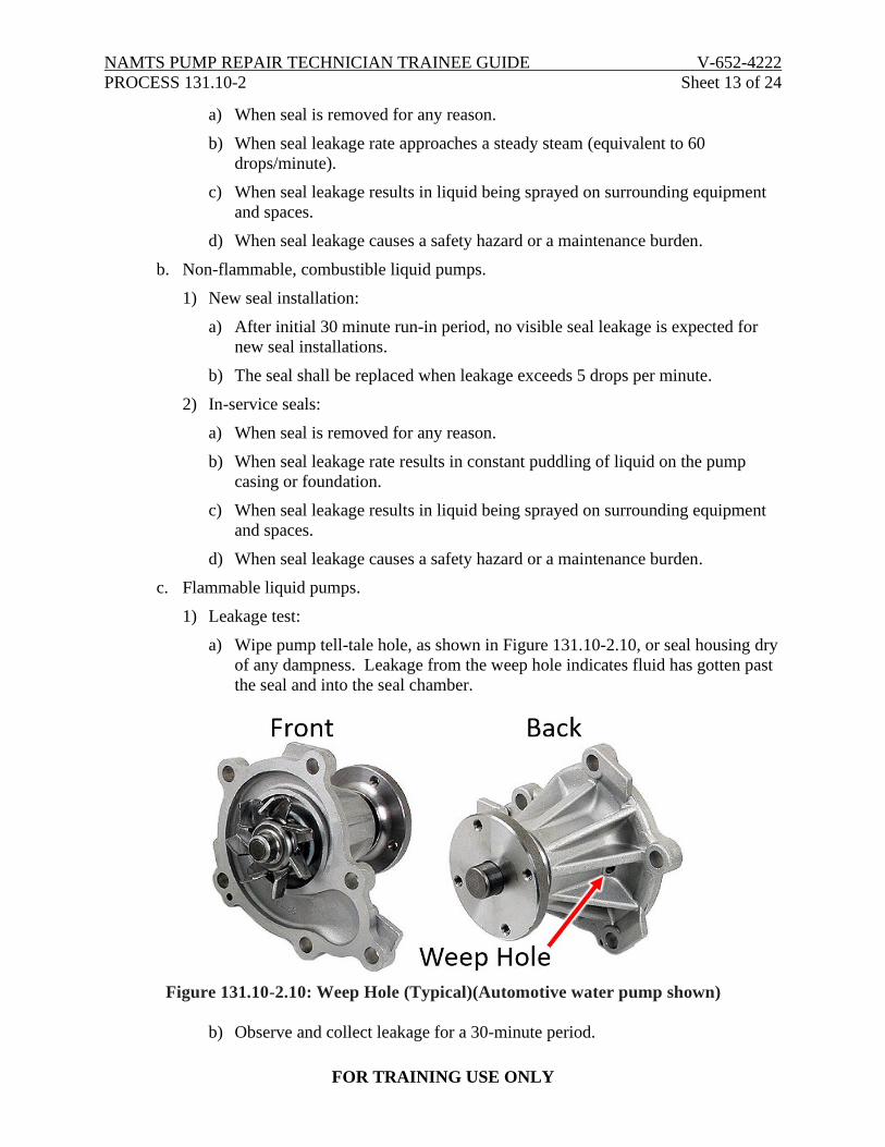
a) Wipe pump tell-tale hole, as shown in Figure 131.10-2.10, or seal housing dry
of any dampness. Leakage from the weep hole indicates fluid has gotten past
the seal and into the seal chamber.
Figure 131.10-2.10: Weep Hole (Typical)(Automotive water pump shown)
b) Observe and collect leakage for a 30-minute period.
Page 14
NAMTS PUMP REPAIR TECHNICIAN TRAINEE GUIDE V-652-4222
PROCESS 131.10-2 Sheet 14 of 24
FOR TRAINING USE ONLY
2) Replacement criterion: Zero measurable (dripping) leakage is permitted over the
30-minute period for satisfactory seal performance (slight dampness at the tell-
tale hole or seal housing is acceptable).
NOTE
If emergency backup packing is installed, the leakage and replacement criteria in NSTM 503, para. 503-5.4.3 for packed stuffing boxes applies.
d. Sewage pumps.
1) Double seals lubricated with oil from a dead-ended reservoir located within the
pump body act as a buffer fluid system to contain the effluent.
2) Leakage test: Visually inspect mechanical seal for oil/sewage leakage as required
by EOSS procedures, technical manual requirements, or routine operating
procedures.
3) Replacement criteria:
a) Zero leakage is acceptable. If oil leakage is detected from the seal, the pump
must be secured, isolated and the seal replaced.
b) Contamination of the oil in the reservoir with sewage does not constitute a
seal failure. The oil in the reservoir should be replaced and periodically
checked as required by applicable PMS. Often, oil may take on a milky
appearance form entrained air. Also, leakage of a few drops of oil outside the
reservoir does not constitute a failure.
10. General installation guidance.
a. Cleanliness.
1) The reliability of a mechanical seal depends on it being free of debris that could
interfere with the proper movement of internal parts or the proper mating of
tightly-toleranced parts.
WARNING
Do not touch a new seal on the sealing face because body acid and grease or dirt will cause the seal to pit prematurely and leak.
2) Use extreme care when handling the seal faces. The lapped surfaces must be kept
clean and free from scratches. Keep the seal faces in their protective wrapping or
covered with a clean, dry, lint-free cloth until installed.
3) If seal faces become soiled, they may be cleaned with water (or another solvent
approved by the seal manufacturer in the instructions specific to that seal) and a
clean, lint-free rag.
Page 15
NAMTS PUMP REPAIR TECHNICIAN TRAINEE GUIDE V-652-4222
PROCESS 131.10-2 Sheet 15 of 24
FOR TRAINING USE ONLY
4) Flush away any debris that might scratch the face before wiping the seal face
clean.
5) Scratched seal faces should generally be replaced, not relapped. However, if the
scratch is minor and a replacement mechanical seal assembly is not available, the
mechanical seal face may be relapped. Lapping instructions with acceptance
criteria specific to the seal, the necessary lapping equipment, and qualified
personnel are required if a seal face is to be relapped. Otherwise, replace the part.
If lapping cannot be done on site, it may be possible to return the part to the seal
manufacturer for relapping and later use.
6) Ensure the spring assembly is clean and free of any debris that could impede its
free axial travel.
b. Burrs and sharp edges.
1) Carefully examine the pump shaft, shaft sleeve, and other parts that have tight
clearances or that come in contact with elastomer parts during installation or
operation.
2) Remove any burrs or sharp edges that could interfere with the tight clearances or
damage the elastomer parts.
c. O-ring fits.
1) Check O-rings installed in grooves for a proper, snug fit.
2) For O-rings which must be stretched over another part during installation, such as
the pump shaft, ensure that sufficient time is provided for the O-ring to contract to
a snug fit before installing the mating part.
d. Lubrication of secondary seal.
1) On pusher type seals, the elastomer secondary seal (e.g. O-ring or U-cup), which
slides on the pump shaft or shaft sleeve in the assembly providing axial flexibility
to the mechanical seal, should be lubricated.
2) The surface against which the secondary seal slides should also be lightly
lubricated in the narrow band where the secondary seal will slide.
3) The lubricant used should only be that specified by the manufacturer for the
specific application. Some elastomer materials are adversely affected by
inappropriate lubricants. For example, Ethylene-Propylene Rubber (EPR)
material swells when lubricated with petroleum-based substances.
CAUTION
Do not use petroleum jelly, Tetrafluoroethylene (TFE), or silicon grease on an elastomer seal. EPR must not be lubricated with any petroleum-based substance.
Page 16
NAMTS PUMP REPAIR TECHNICIAN TRAINEE GUIDE V-652-4222
PROCESS 131.10-2 Sheet 16 of 24
FOR TRAINING USE ONLY
e. Seating of seal faces.
1) The seal face, in the element of the mechanical seal without the spring assembly,
must be squarely seated without cocking to ensure proper seal performance and
prevent secondary seal damage. Otherwise, the sliding secondary seal in the other
element will be subject to a once-per revolution sliding cycle, which can cause
fretting of the elastomer seal and the seal sleeve/pump shaft.
2) When installing the seal face, ensure that the seating surface is free of debris,
burrs, and other upsets that could prevent the seal face from seating properly.
3) If the seal face must be pressed into a recess with an O-ring sealing the outside
diameter, ensure the seal face is fully pressed against the seat during installation.
f. Alignment.
1) Proper alignment is important to reliable operation of a mechanical seal.
2) When installing mechanical seals, ensure that the pump shaft is straight and
centered within the stuffing box within prescribed tolerances.
3) Ensure that the close-tolerance fit, which locates the gland plate in the stuffing
box, is free of debris and burrs and that the gland plate is properly seated when
installed.
4) Before coupling the pump to the drive motor, verify that the axial end-play in the
motor is within tolerances.
5) Ensure that the angular and radial alignment of the pump and its coupling
assembly to the drive motor are within prescribed limits when the pump is
reassembled.
6) In particular, ensure that tapered couplings are properly assembled and that
coupling faces are free of burrs and other debris.
g. Gland plate torqueing.
1) Ensure that the gland-plate bolting is properly torqued and not overtightened.
2) Excessive tightening of the gland-plate bolting can lead to distortion of the gland
plate and stationary seal face.
h. Filling and venting.
1) The pump and stuffing box should be filled with the pumped fluid and fully
vented to remove all of the air from the pump.
2) If some air remains in the pump, the seal faces may not be properly lubricated,
producing overheating of the seal face, wear, and failure.
Page 17
NAMTS PUMP REPAIR TECHNICIAN TRAINEE GUIDE V-652-4222
PROCESS 131.10-2 Sheet 17 of 24
FOR TRAINING USE ONLY
11. Packed stuffing boxes.
a. Description.
1) In a packed stuffing box, the seal between the moving shaft and the stationary
cavity of the stuffing box is accomplished by forcing rings of packing between the
two surfaces, as shown in Figure 131.10-2.11.
Figure 131.10-2.11: Packed Stuffing Box (Typical)
2) A gland holds the packing in the stuffing box and is also used to control the
amount of leakage along the shaft by tightening or loosening the gland nuts.
3) When a pump is designed to work on a suction lift, stuffing boxes are fitted with
lantern rings or seal cages (usually located near the axial center of the stuffing
box) to prevent air leakage into the stuffing box and to lubricate the packing.
b. Sealing liquid.
1) Sealing liquid is injected into the seal cage.
2) When clean, cold water is pumped, the seal water line is usually connected to the
pump casing near the discharge. To avoid excessive pressure in multi-stage
pumps, the connection is to the first stage.
3) An independent external liquid sealing supply is desirable under any of these
conditions:
a) When suction lift is high.
b) When discharge pressure is low.
c) When the pump momentarily runs dry such as with a condensate pump.
d) When pumping hot water.
e) When pumping brine.
f) When pumping water with high chemical content.
Page 18
NAMTS PUMP REPAIR TECHNICIAN TRAINEE GUIDE V-652-4222
PROCESS 131.10-2 Sheet 18 of 24
FOR TRAINING USE ONLY
4) Packing leakage and replacement criteria.
WARNING
Do not air-test a seal using the candle-flame method on a pump handling oil, gasoline, or other flammable liquid.
a) Non-flammable liquids.
i. Take particular care to ensure that seal water piping is open and clean,
allowing adequate flow of seal water to lubricate the packing.
ii. Otherwise, seal or stuffing box packing can wear rapidly from increased
friction, causing shaft scoring, which in turn increases the clearance
between the shaft and the packing, allowing air to be drawn in or fluid to
leak out.
iii. On pumps which operate with a suction lift, test seal efficiency with a
candle flame to see if air is being drawing into the pump.
iv. Even with the pump under a positive suction head, allow water to drip
from the stuffing box to lubricate and cool the packing.
v. Replace packing when the packing gland has been tightened to the point
that it cannot control leakage. Partially replace packing only as a
temporary or emergency action.
b) Flammable liquids.
i. Leakage from flammable liquid pumps (for example fuel oil, JP-5,
gasoline) should be maintained at 1 to 5 drops per minute.
ii. Monitor stuffing boxes carefully when starting the pump. At the first
sign of overheating, stop the pump.
iii. The stuffing boxes should cool before restarting.
iv. When stuffing box leakage must be severely limited, as when pumping a
flammable liquid, packing should be changed as frequently as required to
maintain 1 to 5 drops per minute leakage and prevent shaft scoring.
12. Packing installation procedure.
a. Reactor vs. non-reactor pumps.
1) The packing used in reactor plant pumps shall be in accordance with the pump
technical manuals.
2) All other water service pumps shall be packed with non-asbestos packing in
accordance with MIL-P-24790 and NSTM 503 paragraph 503-5.4.4.1 through
paragraph 503-5.4.4.8, or as otherwise approved by NAVSEA except when the
pump technical manual proprietary non-asbestos packing.
Page 19
NAMTS PUMP REPAIR TECHNICIAN TRAINEE GUIDE V-652-4222
PROCESS 131.10-2 Sheet 19 of 24
FOR TRAINING USE ONLY
3) In the latter case, the packing and procedure in the pump technical manual shall
be followed.
4) Any problems with installing, using, removing, and replacing non-asbestos
packing shall be directed to NAVSEA.
b. Removal.
1) Remove all old packing and lantern ring (seal cage), if installed, from the stuffing
box, being careful not to damage the shaft sleeve.
2) Clean the stuffing box and examine the shaft sleeve for scoring. A deeply scored
or rough shaft sleeve will result in short packing life and should be replaced.
c. Packing preparation.
1) If spool packing is used, cut rings making the ends square.
2) Trim the ends so the butt clearances are 1/8 inch to 3/16 inch when the ring is
wrapped around the shaft sleeve, ensuring the ends remain parallel.
3) If time permits, soak the packing rings in water for several hours before installing.
d. Installing the first packing ring.
1) Install the first ring of packing by inserting the butt joint into the stuffing box.
2) Gradually press the rest of the ring with the fingers, starting at the butt joint and
working around the circumference of the ring until the ring is evenly positioned in
the stuffing box, as shown in Figure 131.10-2.12 and Figure 131.10-2.13.
Figure 131.10-2.12: Packing Ring Installation (Typical)
Page 20
NAMTS PUMP REPAIR TECHNICIAN TRAINEE GUIDE V-652-4222
PROCESS 131.10-2 Sheet 20 of 24
FOR TRAINING USE ONLY
Figure 131.10-2.13; Pushing Packing Ring Flush
3) Press this ring of packing into the stuffing box as far as it will go by installing
gland halves and applying force until the gland contacts the stuffing box, as
shown in Figure 131.10-2.14.
Figure 131.10-2.14: Using Gland to Push in Packing Ring
Page 21
NAMTS PUMP REPAIR TECHNICIAN TRAINEE GUIDE V-652-4222
PROCESS 131.10-2 Sheet 21 of 24
FOR TRAINING USE ONLY
4) Remove gland halves. The ring should fit snugly in the stuffing box without
overlapping the ends. Use this technique to install all the packing rings.
e. Installing the remaining rings.
1) Stagger the joints 90 degrees when installing the remaining packing rings.
2) Where applicable, refer to the technical manual for lantern ring installation.
3) If the last ring does not fit in the box but partially enters the box, do not force the
ring into place; remove it.
4) Refer to the individual equipment technical manual for the number of rings to
install.
f. Gland installation.
1) Install gland or gland halves, as shown in Figure 131.10-2.15, bolt them together,
and then install the gland assembly washers and nuts.
Figure 131.10-2.15: One and Two-piece Packing Glands (Typical)
2) With the gland true to the shaft, finger-tighten the gland nuts until the gland
contacts the top ring of the packing.
3) If enough head is available, apply suction pressure to the pump and allow water to
flow freely from the stuffing box for at least 30 minutes, which provides time for
the packing to absorb water as well as providing lubrication during start-up and
burnout protection.
g. Starting the unit.
1) Run the pump for at least 30 minutes with the gland leaking freely.
2) Over time, gland leakage may decrease when the pump is rotating without
tightening the packing.
Page 22
NAMTS PUMP REPAIR TECHNICIAN TRAINEE GUIDE V-652-4222
PROCESS 131.10-2 Sheet 22 of 24
FOR TRAINING USE ONLY
3) The procedures in NSTM 503, paragraph 503-5.4.4.7 through paragraph 503-
5.4.4.13, are for inspection and adjustments after the shaft has been packed.
h. Gland tightening.
1) Tighten gland nuts in small increments, gradually reducing gland leakage to the
amount specified in the technical manual.
2) If no amount is specified, reduce to a maximum of 32 oz (1 quart)/min. Do not
try to make this adjustment all at one time; wait about 30 minutes between gland
nut adjustments.
3) To ensure that the gland does not cock and compresses the packing evenly,
tighten nuts equally by counting the turns made. Use this procedure whenever
nuts are adjusted.
4) When gland leakage has been significantly reduced, it may be necessary to adjust
gland nuts in small fractions of turns (or flats).
i. Final packing ring.
1) If one ring of packing was left out as allowed in NSTM 503, paragraph 503-
5.4.4.4, secure the pump and suction pressure.
2) When packing has been compressed sufficiently to permit installation of the last
ring, install the additional ring at this time.
j. Leakage adjustments.
1) Continue pump operation, gradually reducing the leakage further. Enough gland
leakage must be maintained to cool the packing. One symptom of inadequate
cooling is steam coming from the stuffing box.
2) When the leakage is 20 to 30 oz/min, gland nut adjustment should not be more
than 1 flat of the nut at a time. Below 20 oz/min, adjustment should be less than
1/2 flat of the nut.
3) Allow about 30 minutes between adjustments to stabilize the packing.
4) Sometimes, when small adjustments are made, the gland nuts can be turned
without a noticeable change in leakage rate. Do not reduce gland leakage too
much, since loosening the gland nuts does not always result in increased gland
leakage.
5) If leakage decreases too rapidly, slack off gland nuts to increase leakage.
6) If the stuffing box heats up, indicating that the packing is overheating, secure the
pump and allow the stuffing box to cool. Loosen the gland nuts about 1/2 turn
and restart the unit. This may restore gland leakage to the minimum required.
k. Minimum gland leakage rate.
1) Depends on four factors:
a) Motor speed.
b) Shaft sleeve diameter.
Page 23
NAMTS PUMP REPAIR TECHNICIAN TRAINEE GUIDE V-652-4222
PROCESS 131.10-2 Sheet 23 of 24
FOR TRAINING USE ONLY
c) Pump internal pressure that the packing is sealing against.
d) Water temperature.
2) As each of these factors increases, the minimum amount of gland leakage that
should be obtained to prevent burning the packing increases, as shown in Figure
131.10-2.16.
Figure 131.10-2.16: Gland Leakage Comparisons
3) For pumps with variable speeds, suction temperatures, or packing sealing
pressures, the minimum gland leakage rate should be adjusted to a rate acceptable
for all operating conditions.
l. Post-installation procedures.
1) Once the packing has been broken-in, limit the amount of leakage to an amount
that will not undesirably affect the equipment or surrounding spaces.
2) Gland leakage, however, should always be less than 32 oz/min.
m. Monitoring.
1) Periodically monitor the packing leakage rate, adjusting the gland nut only when
gland leakage exceeds acceptable rates.
2) When adjusting the gland leakage rate, do not make large or rapid adjustments of
gland nuts, just as during the initial installation.
3) When making adjustments to the stuffing box leak off rate, smoke may be seen
coming from the stuffing box area. If so, secure the pump, isolate the suction, and
discharge and repack the pump with new packing as required by the technical
manual or maintenance requirement card.
Page 24
NAMTS PUMP REPAIR TECHNICIAN TRAINEE GUIDE V-652-4222
PROCESS 131.10-2 Sheet 24 of 24
FOR TRAINING USE ONLY
13. Split mechanical seal installation.
a. Split mechanical seals, such as shown in Figure 131.10-2.17, shall be installed in
accordance with the applicable pump and seal technical manual.
Figure 131.10-2.17: Split Mechanical Seals (Typical)
Page 25
NAMTS PUMP REPAIR TECHNICIAN TRAINEE GUIDE V-652-4222
PROCESS 131.10-2 Sheet 25 of 24
FOR TRAINING USE ONLY
14. Cartridge mechanical seal installation.
a. Cartridge mechanical seals, such as shown in Figure 131.10-2.18, shall be installed in
accordance with the applicable pump and seal technical manual.
Figure 131.10-2.18: Cartridge Mechanical Seals (Typical)