25
LGK-100/160/200IGBT INVERTER AIR PLASMA CUTTING MACHINE OPERA TOR’S MANUAL (PLEASE READ IT CAREFULLY BEFORE OPERATION) CHENGDU HUAYUAN ELECTRIC EQUIPMENT CO., LTD.
| Date post: | 07-Aug-2018 |
| Category: |
Documents |
| Upload: | alfonso-cervantes |
| View: | 702 times |
| Download: | 85 times |

8/20/2019 Lgk Igbt Manual
http://slidepdf.com/reader/full/lgk-igbt-manual 1/25
LGK-100/160/200IGBTINVERTER AIR PLASMA CUTTING MACHINE
OPERATOR’S MANUAL
(PLEASE READ IT CAREFULLY BEFORE OPERATION)
CHENGDU HUAYUAN ELECTRIC EQUIPMENT CO., LTD.

8/20/2019 Lgk Igbt Manual
http://slidepdf.com/reader/full/lgk-igbt-manual 2/25
LGK-100.160.200IGBT OPERATOR’S MANUAL
1
Safety Depends on You
HUAYUAN arc welding and cutting equipments are designed and built with ample safety consideration. However, proper installing
and operating can ensure your safety.
DO NOT INSTALL, OPERATE OR REPAIR THIS EQUIPMENT CASUALLY WITHOUT READING THIS MANUAL
THROUGHOUT.
Special Notes (Very Important):
1. Pay attention to avoiding the machine falling down when it is placed on the gradient ground.
2. It is forbidden to unfreeze the pipeline by the cutter.
3. The shield rank of this series of cutter is IP21S, so working in rain is not suitable.
4.The cutter has external static characteristic with rated duty cycle 100%, which means the machine can work
continuously at the rated cutting current. The machine has the function of thermal protection. When the internal
temperature exceeds a set temperature, thermal protection moves on and the abnormity indicator lamp on the
panel turns ON, then there is no output in cutter. The machine can become normal and work only after the internal
temperature drops down and the abnormity indicator lamp on the panel turns OFF.
Purchase Date:
Serial Number:
Machine Model:
Purchase Place:
8/20/2019 Lgk Igbt Manual
http://slidepdf.com/reader/full/lgk-igbt-manual 3/25
LGK-100.160.200IGBT OPERATOR’S MANUAL
2
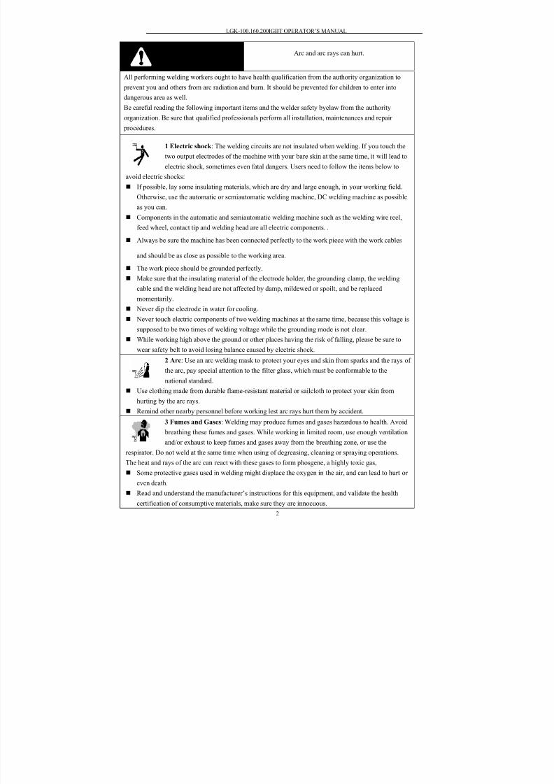
Cautions Arc and arc rays can hurt.
All performing welding workers ought to have health qualification from the authority organization to
prevent you and others from arc radiation and burn. It should be prevented for children to enter into
dangerous area as well.
Be careful reading the following important items and the welder safety byelaw from the authority
organization. Be sure that qualified professionals perform all installation, maintenances and repair
procedures.
1 Electric shock : The welding circuits are not insulated when welding. If you touch the
two output electrodes of the machine with your bare skin at the same time, it will lead to
electric shock, sometimes even fatal dangers. Users need to follow the items below to
avoid electric shocks:
If possible, lay some insulating materials, which are dry and large enough, in your working field.
Otherwise, use the automatic or semiautomatic welding machine, DC welding machine as possible
as you can.
Components in the automatic and semiautomatic welding machine such as the welding wire reel,
feed wheel, contact tip and welding head are all electric components. .
Always be sure the machine has been connected perfectly to the work piece with the work cables
and should be as close as possible to the working area.
The work piece should be grounded perfectly.
Make sure that the insulating material of the electrode holder, the grounding clamp, the welding
cable and the welding head are not affected by damp, mildewed or spoilt, and be replacedmomentarily.
Never dip the electrode in water for cooling.
Never touch electric components of two welding machines at the same time, because this voltage is
supposed to be two times of welding voltage while the grounding mode is not clear.
While working high above the ground or other places having the risk of falling, please be sure to
wear safety belt to avoid losing balance caused by electric shock.
2 Arc: Use an arc welding mask to protect your eyes and skin from sparks and the rays of
the arc, pay special attention to the filter glass, which must be conformable to the
national standard.
Use clothing made from durable flame-resistant material or sailcloth to protect your skin from
hurting by the arc rays.
Remind other nearby personnel before working lest arc rays hurt them by accident.
3 Fumes and Gases: Welding may produce fumes and gases hazardous to health. Avoid
breathing these fumes and gases. While working in limited room, use enough ventilation
and/or exhaust to keep fumes and gases away from the breathing zone, or use the
respirator. Do not weld at the same time when using of degreasing, cleaning or spraying operations.
The heat and rays of the arc can react with these gases to form phosgene, a highly toxic gas,
Some protective gases used in welding might displace the oxygen in the air, and can lead to hurt or
even death. Read and understand the manufacturer’s instructions for this equipment, and validate the health
certification of consumptive materials, make sure they are innocuous.
8/20/2019 Lgk Igbt Manual
http://slidepdf.com/reader/full/lgk-igbt-manual 4/25
LGK-100.160.200IGBT OPERATOR’S MANUAL
3
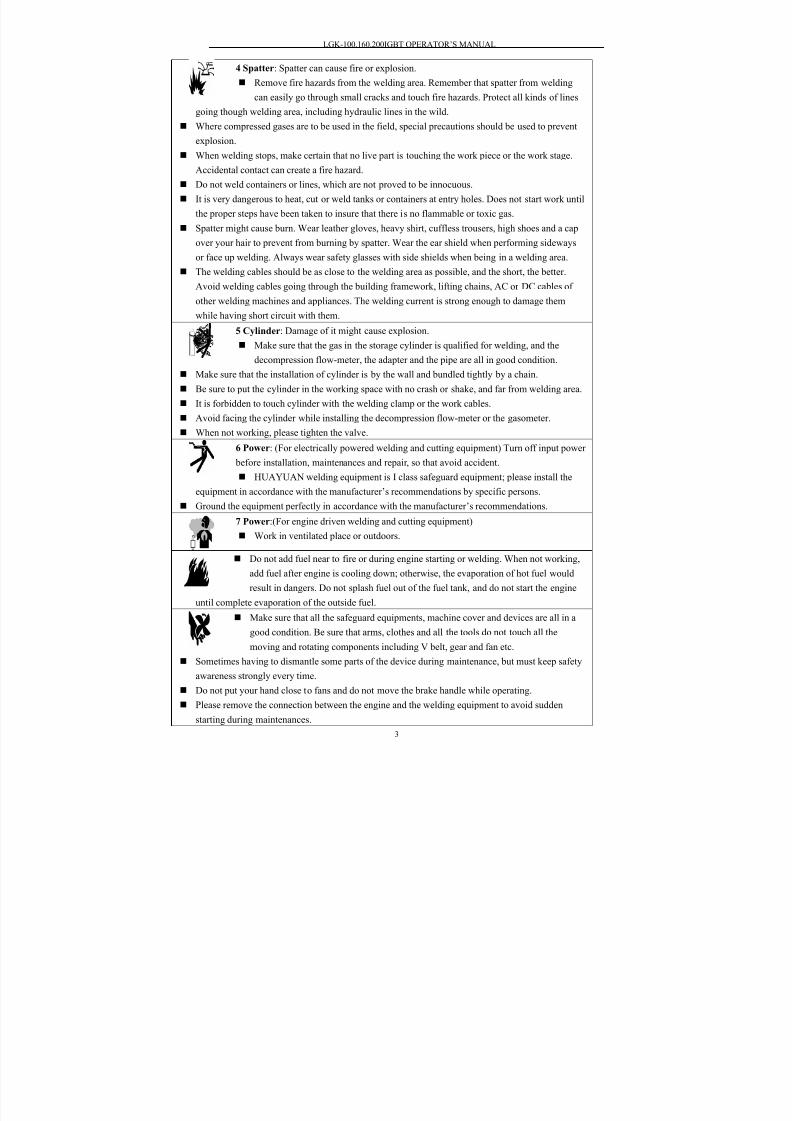
4 Spatter: Spatter can cause fire or explosion.
Remove fire hazards from the welding area. Remember that spatter from welding
can easily go through small cracks and touch fire hazards. Protect all kinds of lines
going though welding area, including hydraulic lines in the wild.
Where compressed gases are to be used in the field, special precautions should be used to prevent
explosion.
When welding stops, make certain that no live part is touching the work piece or the work stage.
Accidental contact can create a fire hazard.
Do not weld containers or lines, which are not proved to be innocuous.
It is very dangerous to heat, cut or weld tanks or containers at entry holes. Does not start work until
the proper steps have been taken to insure that there is no flammable or toxic gas.
Spatter might cause burn. Wear leather gloves, heavy shirt, cuffless trousers, high shoes and a cap
over your hair to prevent from burning by spatter. Wear the ear shield when performing sideways
or face up welding. Always wear safety glasses with side shields when being in a welding area.
The welding cables should be as close to the welding area as possible, and the short, the better.
Avoid welding cables going through the building framework, lifting chains, AC or DC cables of
other welding machines and appliances. The welding current is strong enough to damage them
while having short circuit with them.
5 Cylinder: Damage of it might cause explosion.
Make sure that the gas in the storage cylinder is qualified for welding, and the
decompression flow-meter, the adapter and the pipe are all in good condition.
Make sure that the installation of cylinder is by the wall and bundled tightly by a chain.
Be sure to put the cylinder in the working space with no crash or shake, and far from welding area.
It is forbidden to touch cylinder with the welding clamp or the work cables.
Avoid facing the cylinder while installing the decompression flow-meter or the gasometer.
When not working, please tighten the valve.
6 Power: (For electrically powered welding and cutting equipment) Turn off input power
before installation, maintenances and repair, so that avoid accident.
HUAYUAN welding equipment is Ι class safeguard equipment; please install the
equipment in accordance with the manufacturer’s recommendations by specific persons.
Ground the equipment perfectly in accordance with the manufacturer’s recommendations.
7 Power:(For engine driven welding and cutting equipment)
Work in ventilated place or outdoors.
Do not add fuel near to fire or during engine starting or welding. When not working,
add fuel after engine is cooling down; otherwise, the evaporation of hot fuel would
result in dangers. Do not splash fuel out of the fuel tank, and do not start the engine
until complete evaporation of the outside fuel.
Make sure that all the safeguard equipments, machine cover and devices are all in a
good condition. Be sure that arms, clothes and all the tools do not touch all the
moving and rotating components including V belt, gear and fan etc.
Sometimes having to dismantle some parts of the device during maintenance, but must keep safety
awareness strongly every time.
Do not put your hand close to fans and do not move the brake handle while operating. Please remove the connection between the engine and the welding equipment to avoid sudden
starting during maintenances.

8/20/2019 Lgk Igbt Manual
http://slidepdf.com/reader/full/lgk-igbt-manual 5/25
LGK-100.160.200IGBT OPERATOR’S MANUAL
4
When engine is hot, it is forbidden to open the airtight cover of the radiator water tank to avoid hurt
by the hot vapor.
8 Electromagnetic: Welding current going though any area can generate electromagnetic,
as well as the welding equipment itself.
Electromagnetic would affect cardiac pacemaker, the cardiac pacemaker users should
consult one’s doctor first.
The effect of electromagnetic to one’s health is not confirmed, so it might have some negative
effect to one’s health.
Welders may use following method to reduce the hazardous of electromagnetic:
a. Bundle the cable connected to the work piece and the welding cable together.
b. Do not enwind partially or entirely your body with the cable.
c. Do not place yourself between the welding cable and the ground (work piece) cable, if the welding
cable is by your left side, then the ground cable should be by your left side too.
d. The Welding cable and the ground cable are as short as possible.
e. Do not work near to the welding power source.9 Lift Equipment: carton or wooden boxes package the welding machines supplied by
HUAYUAN. There is no lifting equipment in its wrapper. Users can move it to the
prospective area by a fork-lift truck, and then open the box.
If having rings, the machine can be transited using rings. While HUAYUAN Welding
Machine Manufacture reminds users, there is possible risk to damage the welding
machine. It is better to push the welding machine moving in use of its rollers unless
special situations.
Be sure that the appurtenances are all removed off when lifting.
When lifting, make sure that there is no person below the welding machine, and
remind people passing by at any moment.
Do not move the hoist too fast.
10 Noise: HUAYUAN Welding Machine Manufacture reminds users: Noise beyond the
limit (over 80 db) can cause injury to vision, heart and audition depending on oneself.
Please consult local medical institution. Use the equipment with doctor’s permission
would help to keeping healthy.
8/20/2019 Lgk Igbt Manual
http://slidepdf.com/reader/full/lgk-igbt-manual 6/25
LGK-100.160.200IGBT OPERATOR’S MANUAL
5
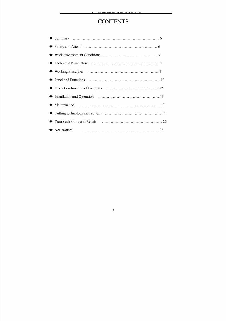
CONTENTS
Summary …………………………………………………………… 6
Safety and Attention ………………………………………………… 6
Work Environment Conditions ……………………………………… 7
Technique Parameters ……………………………………………… 8
Working Principles ………………………………………………… 8
Panel and Functions ………………………………………………… 10
Protection function of the cutter …………………………………….12
Installation and Operation ………………………………………… 13
Maintenance ………………………………………………………… 17
Cutting technology instruction …………………………………………17
Troubleshooting and Repair ………………………………………… 20
Accessories ……………………………………………………… 22

8/20/2019 Lgk Igbt Manual
http://slidepdf.com/reader/full/lgk-igbt-manual 7/25
LGK-100.160.200IGBT OPERATOR’S MANUAL
6
◆ Summary
1. Model description
L G K - 100 IGBT
IGBT Inverter
Rated cutting current
Air plasma
Cutting
Plasma machine
2.
CharacteristicsLGK-100/160/200IGBT inverter air plasma cutting machine is a new generated cutter of
our company. It has good characteristics as following:
1)
This cutting machine adopts IGBT inverter technology which has high reliability and
efficiency. It is light weight.
2) Pre-set current function. Stepless adjustable cutting current, suitable for cutting various
thickness workpiece. To ensure cutting quality and save energy, low current is applied
to cut thin plate, and high current is applied to cut thick plate.
3)
External and dynamic characteristics cutter are significantly better than leakage-reactance
typed cutter. High success rate in striking arc. Stable cutting current. Good arc stiffness.
Clean and smooth incision. Excellent technology performance.4) It has the function of ascending current slowly, which can effectively extend the work
life of wearing parts and cutting torch.
5)
Quite suitable for CNC automatic cutting and has all signal output which is required by
CNC control.
6) The cutting current is very stable and it will not be influenced by grid voltage
fluctuation.
7) 100% duty cycle. It can work continuously under max current.
8)
Have over/ under voltage and phase missing protection function.
3. Usage
It is suitable for cutting kinds of metal materials like low carbon steel, alloy steel and
non-ferrous metal and is widely applied in the manufacturing of boiler pressure container,
chemical container, industrial power station construction, metallurgy, aerospace industry,
automobiles, building an so on.
Safety and Attention
Please follow the notes for the safety of you and others.
It is forbidden to unfreeze the pipe line by cutting power or other usages except for
cutting.

8/20/2019 Lgk Igbt Manual
http://slidepdf.com/reader/full/lgk-igbt-manual 8/25
LGK-100.160.200IGBT OPERATOR’S MANUAL
7
The cutter casing should ground reliably. Please make sure the grounding bolts of
power ground reliably in case of electric shock.
Cutter is the equipment with high voltage. Please wear insulated protective shield
when cutting.
When exchanging torch and wearing parts, please turn off the supply power first.
Protective shield should be worn.In order to avoid any hurt to eyes from ultraviolet radiation and strong light and to skin
from spatter, please wear protective shield according to related rules and regulations of
labor protection.
It is forbidden to inhale harmful gases.
The fumes and gases produced during cutting is hazardous to health. Please wear
protective shields and install aerator according to related rules and regulations of labor
protection.
Cutting cannot proceed in closed container.
The workpiece just after being cut is at high temperature. Please prevent from scald. Protective gas cylinder and air compressor must be placed in a fixed position and
prevented from collision.
Cutter and cutting place should be far away from flammable materials.
Prevent foreign bodies from entering inside the machine. And protect the cable from
sharp materials.
Protect the machine from fall or collision.
In case of fall or collision, it can be used only after professional checking.
In the surface or inside of the cutting workpiece, there should be no flammable and
explosive materials or chemical materials harmful to human.
Installation and repair person must have state-authorized electrician operationcertificate.
Cutting operation person should read this manual carefully and know the operation
method well.
◆ Work Environment Requirements
Welding performance may not meet technique standards without the following conditions.
1. It should be placed with small dust, no corrosive gases and no flammable and explosive
materials. Avoid vertical sunshine and rain;
2. Air relative humidity is no more than 90% at 20 and no more than 50% at 40℃ ℃
3. When using air cooling torch, the ambient temperature should be from -10 to 40 .℃ ℃
4. It should avoid metal foreign bodies entering into the cutting power.
5. Cutting power should be 30cm away from the wall or other sealed-in objects. The
distance between two sets should be above 30cm.
6. The operation height should be less than 1000m.
Technique Parameters
1. Main technique parameters
LGK-100IGBT LGK-160IGBT LGK-200IGBT
Shell shield rank IP21S
Rated input voltage 3~50Hz 380V
8/20/2019 Lgk Igbt Manual
http://slidepdf.com/reader/full/lgk-igbt-manual 9/25
LGK-100.160.200IGBT OPERATOR’S MANUAL
8
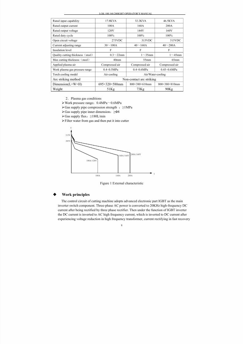
Rated input capability 17.8KVA 32.2KVA 46.5KVA
Rated output current 100A 160A 200A
Rated output voltage 120V 144V 160V
Rated duty cycle 100% 100% 100%
Open circuit voltage 275VDC 315VDC 315VDC
Current adjusting range 30~100A 40~160A 40~200A
Insulation level F F F
Quality cutting thickness(steel) 0.3~22mm 1~35mm 1~45mm
Max cutting thickness(steel) 40mm 55mm 65mm
Applied plasma air Compressed air Compressed air Compressed air
Work plasma gas pressure range 0.4~0.5MPa 0.4~0.6MPa 0.45~0.6MPa
Torch cooling model Air-cooling Air/Water-cooling
Arc striking method Non-contact arc striking
Dimension(L×W×H) 695×320×580mm 800×380×610mm 800×380×810mmWeight 51Kg 73Kg 90Kg
2.Plasma gas conditions
Work pressure range:0.4MPa~0.6MPa
Gas supply pipe compression strength :≥1MPa
Gas supply pipe inner dimension:≥Φ8
Gas supply flux:≥180L/min
Filter water from gas and then put it into cutter
Figure 1 External characteristic
◆ Work principles
The control circuit of cutting machine adopts advanced electronic part IGBT as the main
inverter switch component. Three-phase AC power is converted to 20KHz high-frequency DC
current after being rectified by three phase rectifier. Then under the function of IGBT inverter
the DC current is inverted to AC high frequency current, which is inverted to DC current after
experiencing voltage reduction in high frequency transformer, current rectifying in fast recovery
1 6 0 AI
1 0 0 A 2 0 0 A
U
2 8 5 V
3 1 5 V
2 0 0 A / 1 6 0 V1 6 0 A / 1 4 4 V
1 0 0 A / 1 2 0 V
8/20/2019 Lgk Igbt Manual
http://slidepdf.com/reader/full/lgk-igbt-manual 10/25
LGK-100.160.200IGBT OPERATOR’S MANUAL
9
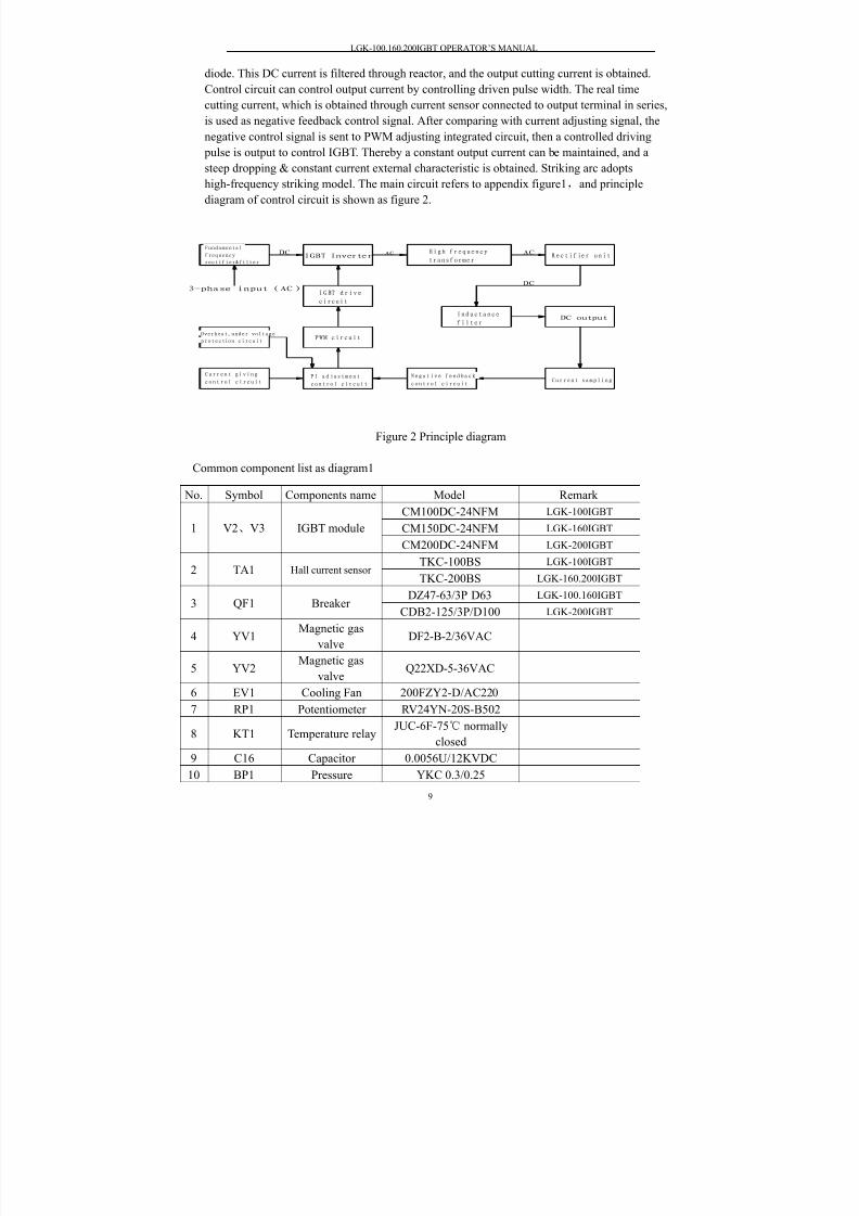
diode. This DC current is filtered through reactor, and the output cutting current is obtained.
Control circuit can control output current by controlling driven pulse width. The real time
cutting current, which is obtained through current sensor connected to output terminal in series,
is used as negative feedback control signal. After comparing with current adjusting signal, the
negative control signal is sent to PWM adjusting integrated circuit, then a controlled driving
pulse is output to control IGBT. Thereby a constant output current can be maintained, and asteep dropping & constant current external characteristic is obtained. Striking arc adopts
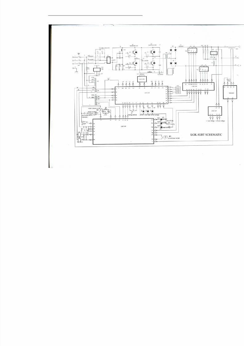
high-frequency striking model. The main circuit refers to appendix figure1,and principle
diagram of control circuit is shown as figure 2.
ACDC
DC
AC
3-phase input(AC)
IGBT Inverter
DC output
I G BT d r i v e
circuit
Fundamental
frequency
rectifier&filterRectifier unit
C u r r e n t s a m p l i n g
Inductance
filter
High frequency
transformer
N e g a t i v e f e e d b a c k
c o n t r o l c i r c u i t
Overheat,under voltage
protection circuit
C u r r e n t g i v i n g
c o n t r o l c i r c u i tP I a d j u s t m e n t
c o n t r o l c i r c u i t
PWM circuit
Figure 2 Principle diagram
Common component list as diagram1
No. Symbol Components name Model Remark
CM100DC-24NFM LGK-100IGBT
CM150DC-24NFM LGK-160IGBT1 V2、V3 IGBT module
CM200DC-24NFM LGK-200IGBT
TKC-100BS LGK-100IGBT2 TA1 Hall current sensor
TKC-200BS LGK-160.200IGBT
DZ47-63/3P D63LGK-100.160IGBT
3 QF1 BreakerCDB2-125/3P/D100 LGK-200IGBT
4 YV1Magnetic gas
valveDF2-B-2/36VAC
5 YV2Magnetic gas
valveQ22XD-5-36VAC
6 EV1 Cooling Fan 200FZY2-D/AC220
7 RP1 Potentiometer RV24YN-20S-B502
8 KT1 Temperature relayJUC-6F-75℃ normally
closed
9 C16 Capacitor 0.0056U/12KVDC
10 BP1 Pressure YKC 0.3/0.25
8/20/2019 Lgk Igbt Manual
http://slidepdf.com/reader/full/lgk-igbt-manual 11/25
LGK-100.160.200IGBT OPERATOR’S MANUAL
10
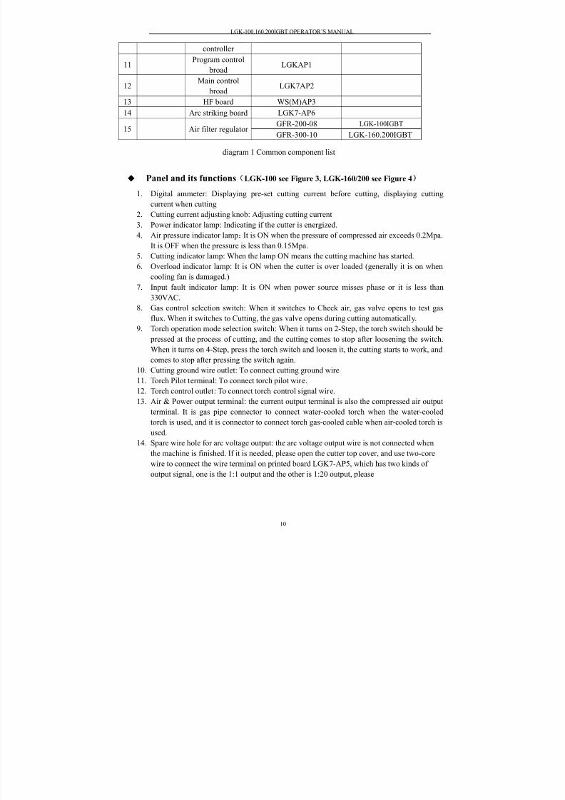
diagram 1 Common component list
Panel and its functions(LGK-100 see Figure 3, LGK-160/200 see Figure 4)
1.
Digital ammeter: Displaying pre-set cutting current before cutting, displaying cuttingcurrent when cutting
2. Cutting current adjusting knob: Adjusting cutting current
3.
Power indicator lamp: Indicating if the cutter is energized.
4. Air pressure indicator lamp:It is ON when the pressure of compressed air exceeds 0.2Mpa.
It is OFF when the pressure is less than 0.15Mpa.
5. Cutting indicator lamp: When the lamp ON means the cutting machine has started.
6. Overload indicator lamp: It is ON when the cutter is over loaded (generally it is on when
cooling fan is damaged.)
7. Input fault indicator lamp: It is ON when power source misses phase or it is less than
330VAC.8. Gas control selection switch: When it switches to Check air, gas valve opens to test gas
flux. When it switches to Cutting, the gas valve opens during cutting automatically.
9.
Torch operation mode selection switch: When it turns on 2-Step, the torch switch should be
pressed at the process of cutting, and the cutting comes to stop after loosening the switch.
When it turns on 4-Step, press the torch switch and loosen it, the cutting starts to work, and
comes to stop after pressing the switch again.
10. Cutting ground wire outlet: To connect cutting ground wire
11.
Torch Pilot terminal: To connect torch pilot wire.
12. Torch control outlet: To connect torch control signal wire.
13. Air & Power output terminal: the current output terminal is also the compressed air output
terminal. It is gas pipe connector to connect water-cooled torch when the water-cooled
torch is used, and it is connector to connect torch gas-cooled cable when air-cooled torch is
used.
14. Spare wire hole for arc voltage output: the arc voltage output wire is not connected when
the machine is finished. If it is needed, please open the cutter top cover, and use two-core
wire to connect the wire terminal on printed board LGK7-AP5, which has two kinds of
output signal, one is the 1:1 output and the other is 1:20 output, please
controller
11Program control
broadLGKAP1
12Main control
broadLGK7AP2
13 HF board WS(M)AP3
14 Arc striking board LGK7-AP6
GFR-200-08 LGK-100IGBT15 Air filter regulator
GFR-300-10 LGK-160.200IGBT

8/20/2019 Lgk Igbt Manual
http://slidepdf.com/reader/full/lgk-igbt-manual 12/25

8/20/2019 Lgk Igbt Manual
http://slidepdf.com/reader/full/lgk-igbt-manual 13/25
LGK-100.160.200IGBT OPERATOR’S MANUAL
12
positive electrode.
15. Control signal connector: To control automatic cutting equipment
16.
Power source switch: Control the ON/OFF of 3-phase power supply of cutter
17.
Air pressure regulation filter :For adjusting work pressure of compressed air and filtrating
water from air.
18.
Hydraulic pressure indicating lamp: connect the cooling water supply, when water currentis bigger than 0.45L/min, the lamp will be on.
19.
Gas-cooled torch/water-cooled torch selection switch: gas-cooled torch is used only when
it switches to gas cooling, and water-cooled torch is used under water cooling mode
selected.
20. Water/Power output terminal: the cutting current output terminal is also the water output
terminal, it is used to connect the water cooling cable.
21.
Backwater terminal of the torch: It is used to connect the water recycle pipe.
22.
Backwater terminal: it is used to connect the water tank recycle pipe.
23.
Water input terminal: it is used to connect the water tank output pipe.
◆ Protection function of the cutter
Air pressure protection
1. When the indicated value of the pressure meter, which is fixed on the back of the cutter, is
lower than 0.2 MPa, the protection circuit starts working and the cutter cannot start.
2. When the indicated value is lower than 0.15 MPa during cutting, the cutting arc will
extinguish.
Note: When adjust the air pressure, the panel function must be set to ‘air checking’.
Water pressure protection(LGK-100 does not have this function)
1.
When the water supply is lower than 0.45L/min, protection circuit starts working and cutter
cannot start.
When the water supply is lower than 0.4L/min during the process, protection circuit starts
working and cutting arc extinguishes automatically.
Over-heat protection
When the ambient temperature is too high or the cooling fan is broken, the cutter will beover heated under the rated current, and heat protection circuit starts working, the cutting arc
will extinguish automatically.
Abnormal power supply protection
1. When 3 phases power supply misses phase, protection circuit starts working and there is no
arc striking.
2. When 3 phrase power supply is lower than 330VAC, protection circuit starts working and
there is no arc striking.
Note: the water and air pressure protection function is for protecting the torch only.
◆ Installation and Operation

8/20/2019 Lgk Igbt Manual
http://slidepdf.com/reader/full/lgk-igbt-manual 14/25
LGK-100.160.200IGBT OPERATOR’S MANUAL
13
1. Transport and Lift
A. Power source should be shut off before moving the cutter.
B. The cutter bottom should be kept downwards during transportation. It is forbidden to have
cutter placed transversely or upended.
C. When lifting, it must be lifted vertically.
D. During the long-distance transportation, it must prevent the cutter from raining andmoving back and forth inside box. Shock absorption foam should be placed around cutter.
2. Installation and Connection
A.
Power source should be shut off before installation and connection.
B. Installation environment details refers to the point “Work Environment Requirements”.
C. If cutting power source is placed in a slanted surface, it must be prevented from falling
down.
D.
Shield rank for cutting power is IP21S. The installation and operation cannot be
proceeded in the rain.
3.
Power supply requirementsA. Voltage fluctuation≤±10%;
B. Frequency fluctuation≤±1%;
C.
Asymmetry rate of three-phase supply system≤5%;
D. Power supply wire cross profile, ground wire cross profile, breaker and fuse should
refer to the diagram below.
Items LGK-100 LGK-160 LGK-200
Power supply wire cross profile
(mm2)
≥6 ≥10 ≥16
Ground wire cross profile(mm2) ≥6 ≥10 ≥16
Breaker capacity(A) 80A 100A 160A
Fuse capacity(A) 45 60 90
4. Installation of power wire
Shut off the power switch first. Connect the power input wire of cutter back panel to distribution
box which meets the parameters in the diagram above.
5.
Connection of ground wire
Connect the green-yellow wire of power source line, which cross profile must match the
requirements in above form, to ground firmly. Earth connecting method should follow state
standard.
6. Connection of compressed gas.

8/20/2019 Lgk Igbt Manual
http://slidepdf.com/reader/full/lgk-igbt-manual 15/25
LGK-100.160.200IGBT OPERATOR’S MANUAL
14
Hoop
Gas pressure
regulating valve
Inlet pipe
Draining water tip
The compressed gas should meet the requirement mentioned in point “Plasma gasconditions”. Connect the gas pipe with the gas inlet of air filter on the back panel and hoop it
tightly.
The usage of air filter regulator is as follows. When it is to adjust pressure, lift up air
pressure regulating valve, and rotate it. Left rotation aims to reduce outlet gas pressure, right
rotation aims to increase outlet gas pressure. After the gas pressure is adjusted properly, press
down regulating valve.
The air filter regulator should be checked periodically. If the water level reaches two-thirds
of filter glass, it must be drained, or this will affect incision quality. The gas supply valve
should be closed during water draining, and Gas Checking function is selected in panel. When
the indicated valve of gas pressure meter is zero, water will drain out from drainage mouthautomatically.
7. Connection of cooling water (LGK-100 does not have this function)
Connect the copper nozzle marked with “water inlet” on the cutter back side with water
supply pipe, and tighten it. Connect the copper nozzle marked with “Backwater” with water
recycle pipe, and tighten it.
Notes: when apply gas cooling torch, the torch selection switch on panel must be set to air-cooled
torch position, and the cooling water cannot be connected with. The cooling water is for cooling
torch only, and cutter power source does not need water cooling.
8. Connection of cutting torch
Torch connection
The torch model matched to plasma power source is as below:
Power source model LGK-100 LGK-160 LGK-200
Torch model P80 air-cooled 160 water-cooled 200 water-cooled
Note Can match air-cooled torch P80
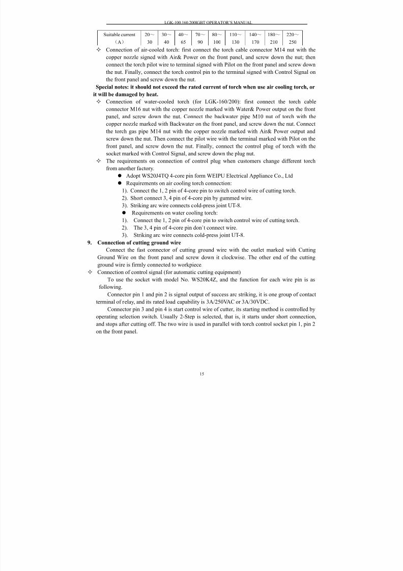
The selection of torch nozzle
The best current range for different nozzles is different. Please select the nozzle
according to below form.
Nozzle aperturedia.(mm)
1.0 1.2 1.4 1.6 1.8 2.0 2.2 2.4 2.6
8/20/2019 Lgk Igbt Manual
http://slidepdf.com/reader/full/lgk-igbt-manual 16/25
LGK-100.160.200IGBT OPERATOR’S MANUAL
15
Suitable current
(A)
20~
30
30~
40
40~
65
70~
90
80~
100
110~
130
140~
170
180~
210
220~
250
Connection of air-cooled torch: first connect the torch cable connector M14 nut with the
copper nozzle signed with Air& Power on the front panel, and screw down the nut; then
connect the torch pilot wire to terminal signed with Pilot on the front panel and screw down
the nut. Finally, connect the torch control pin to the terminal signed with Control Signal on
the front panel and screw down the nut.
Special notes: it should not exceed the rated current of torch when use air cooling torch, or
it will be damaged by heat.
Connection of water-cooled torch (for LGK-160/200): first connect the torch cable
connector M16 nut with the copper nozzle marked with Water& Power output on the front
panel, and screw down the nut. Connect the backwater pipe M10 nut of torch with the
copper nozzle marked with Backwater on the front panel, and screw down the nut. Connect
the torch gas pipe M14 nut with the copper nozzle marked with Air& Power output and
screw down the nut. Then connect the pilot wire with the terminal marked with Pilot on thefront panel, and screw down the nut. Finally, connect the control plug of torch with the
socket marked with Control Signal, and screw down the plug nut.
The requirements on connection of control plug when customers change different torch
from another factory.
Adopt WS20J4TQ 4-core pin form WEIPU Electrical Appliance Co., Ltd
Requirements on air cooling torch connection:
1). Connect the 1, 2 pin of 4-core pin to switch control wire of cutting torch.
2). Short connect 3, 4 pin of 4-core pin by gummed wire.
3). Striking arc wire connects cold-press joint UT-8.
Requirements on water cooling torch:1). Connect the 1, 2 pin of 4-core pin to switch control wire of cutting torch.
2). The 3, 4 pin of 4-core pin don`t connect wire.
3). Striking arc wire connects cold-press joint UT-8.
9. Connection of cutting ground wire
Connect the fast connector of cutting ground wire with the outlet marked with Cutting
Ground Wire on the front panel and screw down it clockwise. The other end of the cutting
ground wire is firmly connected to workpiece.
Connection of control signal (for automatic cutting equipment)
To use the socket with model No. WS20K4Z, and the function for each wire pin is asfollowing.
Connector pin 1 and pin 2 is signal output of success arc striking, it is one group of contact
terminal of relay, and its rated load capability is 3A/250VAC or 3A/30VDC.
Connector pin 3 and pin 4 is start control wire of cutter, its starting method is controlled by
operating selection switch. Usually 2-Step is selected, that is, it starts under short connection,
and stops after cutting off. The two wire is used in parallel with torch control socket pin 1, pin 2
on the front panel.
8/20/2019 Lgk Igbt Manual
http://slidepdf.com/reader/full/lgk-igbt-manual 17/25
LGK-100.160.200IGBT OPERATOR’S MANUAL
16
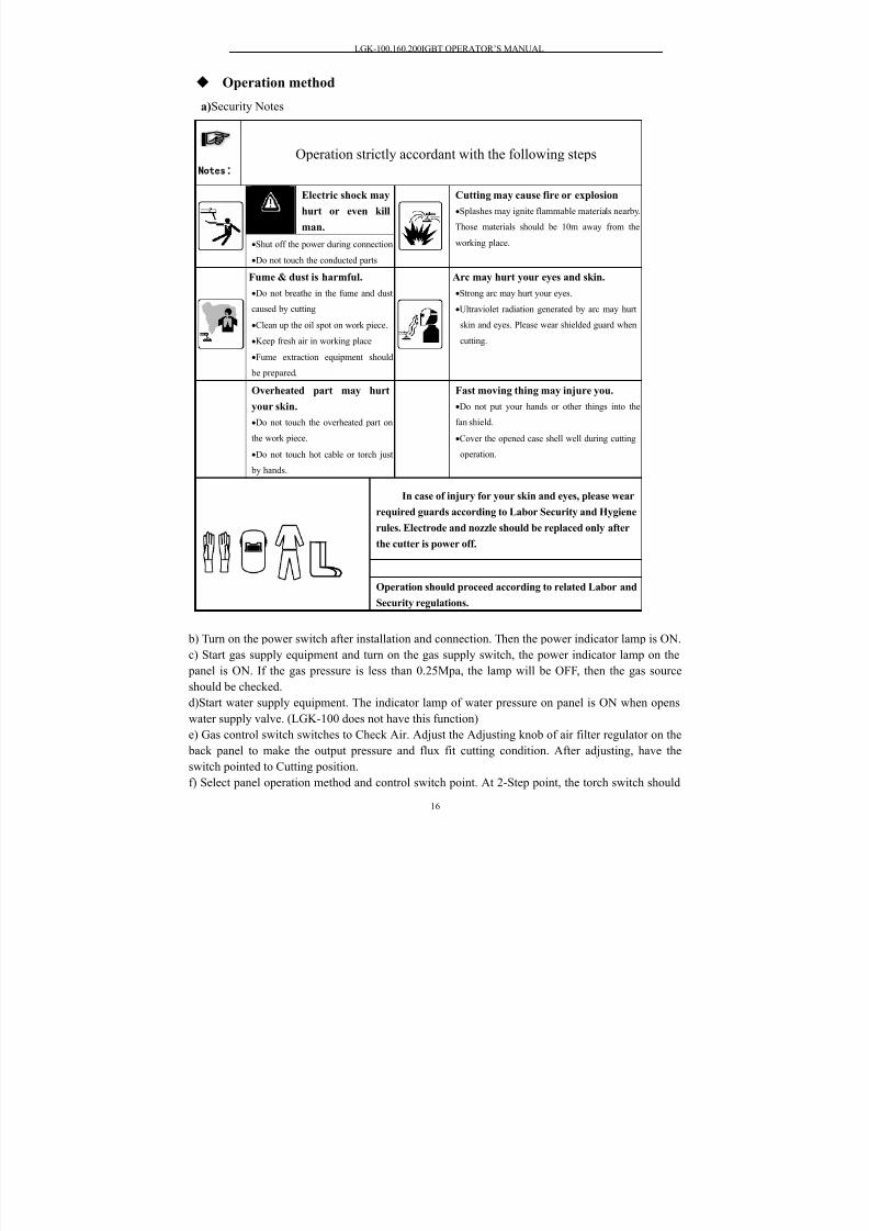
Operation method
a)Security Notes
b) Turn on the power switch after installation and connection. Then the power indicator lamp is ON.
c) Start gas supply equipment and turn on the gas supply switch, the power indicator lamp on the
panel is ON. If the gas pressure is less than 0.25Mpa, the lamp will be OFF, then the gas source
should be checked.
d)Start water supply equipment. The indicator lamp of water pressure on panel is ON when opens
water supply valve. (LGK-100 does not have this function)
e) Gas control switch switches to Check Air. Adjust the Adjusting knob of air filter regulator on the
back panel to make the output pressure and flux fit cutting condition. After adjusting, have the
switch pointed to Cutting position.
f) Select panel operation method and control switch point. At 2-Step point, the torch switch should
Notes
Operation strictly accordant with the following steps
Notice
Electric shock may
hurt or even kill
man.
•Shut off the power during connection
•Do not touch the conducted parts
Cutting may cause fire or explosion
•Splashes may ignite flammable materials nearby.
Those materials should be 10m away from the
working place.
Fume & dust is harmful.
•Do not breathe in the fume and dust
caused by cutting
•Clean up the oil spot on work piece.
•Keep fresh air in working place
•Fume extraction equipment should
be prepared.
Arc may hurt your eyes and skin.
•Strong arc may hurt your eyes.
•Ultraviolet radiation generated by arc may hurt
skin and eyes. Please wear shielded guard when
cutting.
Overheated part may hurt
your skin.
•Do not touch the overheated part on
the work piece.
•Do not touch hot cable or torch just by hands.
Fast moving thing may injure you.
•Do not put your hands or other things into the
fan shield.
•Cover the opened case shell well during cutting
operation.
In case of injury for your skin and eyes, please wear
required guards according to Labor Security and Hygiene
rules. Electrode and nozzle should be replaced only after
the cutter is power off.
Operation should proceed according to related Labor and
Security regulations.

8/20/2019 Lgk Igbt Manual
http://slidepdf.com/reader/full/lgk-igbt-manual 18/25
LGK-100.160.200IGBT OPERATOR’S MANUAL
17
be pressed all the time during cutting. After loosening, the cutting comes to stop. At 4-Step point,
press the torch switch and then loosen it, and cutting can start. User can make selection according to
his operation habit.
g) Checking the panel indicator lamps. The indicator lamps status, under which cutting can be
operated, is shown as following diagram.
Indicator
Lamp
Power Cutting Gas
pressure
Water
pressure
Overheated Supply
abnormity
Status ON OFF ON ON OFF OFF
Notes: there is no water pressure indicator lamp for LGK-100, and the water pressure lamp will
not be ON when gas-cooled torch is applied in LGK-160/200 cutter.
h)Keep the torch nozzle 2 to 5mm away from workpiece. The axis line of nozzle should be
perpendicular to workpiece, and starts cutting from the edge of workpiece. When the plate thickness
is ≤12mm, a hole can be drilled on workpiece and then cutting can be started around the hole. The
cutting torch should inclined to one side a little during drilling a hole on workpiece, so that the
molten metal can be blown away easily. To drill a hole by use of plasma arc is not proposed, because this will damage nozzle easily, it is better to drill a hole in arc striking point first, then
strikes arc on the edge of hole. Press down torch switch, compressed gas sprays out from nozzle,
and cutting indicating lamp is ON. After gas pre-flows for 1 to 2 seconds, high frequency is
generated, arc is struck, and cutting begins by moving torch.
i)When the control switch of operation method on front panel is at 2-Step point, press down the
torch switch and cutting starts after arc striking. After loosening the switch, there is no voltage
output, and cutting ends, and compressed gas stops supply in 9 seconds. When it is at 4-Step point,
press down the switch and loosen it, and cutting starts after arc striking automatically. Press the
switch again or press it till the arc is off, then there is no voltage output, cutting ends, and
compressed gas stops supply in 9 seconds.
Maintenance
The cutter cannot be operated and placed in strong sunshine.
2. The cutter cannot be operated and placed in moist environment.
3. The vent hole should not be covered when the cutter is operated.
4. The cutter should be operated and placed in drafty environment.
5. The cutter casing should be opened once a year at least. Clean up the dust and metal scraps
inside the machine by use of compressed gas.
6. Check regularly if the cable insulation cover is damaged. If there is any damage, repair it orchange it.
7. Check regularly if the electric connection is loose and then tighten it.
8. Drain out regularly the water and impurities from filtering reducing valve.
Notes: When maintaining the cutter, professional electrician is required to dismantle
the power wire from distribution box and open the machine casing.
Cutting technology instruction
1.
The related main technical parameters
Cutting material and thickness
The selection of cutting technical parameters is based on the cutting material and thickness.
If the material is thick, it should adopt large current and nozzle with big aperture. For different

8/20/2019 Lgk Igbt Manual
http://slidepdf.com/reader/full/lgk-igbt-manual 19/25
LGK-100.160.200IGBT OPERATOR’S MANUAL
18
material under the same thickness, the parameter should also be different.
Nozzle selection
The three main dimension of nozzle are the diameter of nozzleφ, the hole pass length ι and
the compacted angle α, they all can affect the cutting. There should be a certain proportion
between ι and φ, the value is usually lower than 2, and it usually takesι=1.5 ∼1.8
Φ
, the
compact angle usually takes α=30°~60°, and now it usually takes α=30°.
Cutting current and arc voltage
The selection of cutting current should be according to the diameter of the nozzle, the
relationship between the two should be as: I(current A)=(70~100)×φ(mm). As the increase of
the metal thickness, the influence of arc current to the cutting speed will become less. But as
the increase of current, the burning damage will be worse for the electrode and the nozzle. So
when cutting a thick metal workpiece, usually the increase of cutting speed is made by
increasing arc voltage. The actual arc voltage is decided not only by the gas type but also by the
air flux and nozzle shape. Working voltage increases with the increase of gas flux. Gas flow Q
The arc voltage increases as the increase of air flow, that is, the arc power, the cutting speed,
as well as the cutting capacity and quality is improved accordingly. Because the arc
compression level increases, the energy is more concentrated, the arc beam temperature, the arc
spraying speed, as well as the arc current impulsion increases. But overlarge current may cause
the instability of the plasma arc. Usually no change is made to air flow for one torch. But it can
be adjusted a little when the cutting torch or cutting thickness is different.
Electrode inner contractionΔLy
When electrode inner contraction ΔLy is so small that electrode extends into spray hole,
electrode is damaged seriously by air flow impact and the combination function between hightemperature gas and electrode. This leads to the instability of plasma arc, weak compression
effect, and weak cutting penetration ability that cutting cannot be proceeded. If ΔLy is too big,
the arc is so unstable that the cutting ability is weakened. The electrode end should be placed
within siphoning zone of gas current under a relative vacuum condition, and it will difficult to
damage electrode by burning, as well as this is beneficial for compression of arc. ΔLy is about
2-4mm.
The distance between the nozzle and the workpiece (d)
If the d is too big, the blow power of plasma arc for molten metal decreases, so does the
cutting ability, and the burr on the bottom increases, meanwhile the instability of the arc
increases. However, if the d is too small, it increases the possibility of short circuit between the
nozzle and the workpiece. Usually d should be as small as possible on condition that no short
circuit is caused between nozzle and workpiece. The d under normal cutting of air plasma is
usually 2~5mm. The workpiece can also contact with the nozzle during air plasma cutting,
that is, the nozzle glide on the surface of the workpiece. This cutting method is called contact
cutting, and the cutting thickness is the half as the ordinary cutting.
Open circuit voltage
The power source with high open circuit voltage is required for cutting thick workpiece.
The open circuit voltage is related with air type, for example, by using argon the open circuit
voltage may be lower, while it is higher by using air, nitrogen, hydrogen. Cutting speed
The cutting speed is related with many parameters. The main parameters determining
8/20/2019 Lgk Igbt Manual
http://slidepdf.com/reader/full/lgk-igbt-manual 20/25
LGK-100.160.200IGBT OPERATOR’S MANUAL
19
cutting speed include workpiece thickness, cutting current, air flux and nozzle aperture. A
proper drag is allowed during cutting. The cutting speed should be increased as much as
possible, but the incision quality must be guaranteed.
2.
Eliminate the cutting burr
The characteristics of the incision burr
The ordinary cutting surface is smooth and clean, but if the parameter selection is notsuitable, and electrode centering is not good, then burr may be formed on the cutting
surface.
Slag is formed by molten metal and its oxide which is adhesive to the bottom edge of
incision and solidified. The reason for forming this slag is that the molten metal adhesive
strength is bigger than the gravity and blow strength of metal oxide.
When cutting the alloy steel, the molten metal is difficult to be blown away because
of its bad fluidity, in addition, the alloy steel have bad thermal conductivity, the incision
bottom is over-heated easily, the left molten metal and incision bottom melts into one,
thereby the irremovable and tough burr is formed.On the contrary, the incision bottom is difficult to be melted together with molten
metal, and the burr formed under incision is come off easily.
The factors affecting the forming of burr
The fluidity of the molten metal is not good, when the power is too small or the plasma
arc compression effect is not good, the temperature of molten metal during the cutting
process is low, fluidity is weak, even if the air current blow force is strong, it is still
difficult to blow away the metal completely, so the burr is formed.
When cutting the thick plate, the burr is caused by the drag of overlarge cutting seam.
During the cutting process, the heat received by different parts of metal is different, the
heat on the upper incision is larger than that of the lower incision, so the upper partmelting speed is faster than that of lower part, thereby a distance between them is formed,
it is called drag L of cutting seam. The drag size is related to plasma arc shape and cutting
speed. When the flame is short while the cutting speed is too fast, drag L increases, so
the vertical and horizontal blow force of the arc is formed, the vertical one helps to blow
away the molten metal, while the horizontal one makes the molten metal flow backward
along with incision bottom, this over-heated metal will melt parts of the bottom metal
again, then the burr is formed when they cool down and melt together.
The burr is caused by overheat bottom. When the cutting speed is too slow, but the
incision bottom is so over-heated that it melts, the liquid metal flows to bottom metal and
combines into one which makes the difficulty to blow away molten metal by air current,
and then the burr is formed.
The air current blow force is not enough. When cutting with plasma, the arc blow force
consists of the air current blow force and the arc electromagnetic force, the air current
blow force acts the main function. If the air current blow force is not strong enough, it
cannot ensure all the burr is flown away, then the burr is formed.
The measurement to eliminate burr
Ensure the centering between electrode and nozzle precisely, so that the compression
of the plasma arc is not damaged, the concentration of flame and cutting capacity can be
guaranteed. Enough power to ensure the fluidity of molten metal, as well as increase the stability
of the cutting speed and operation. This makes it possible to adopt large air flux to enlarge
8/20/2019 Lgk Igbt Manual
http://slidepdf.com/reader/full/lgk-igbt-manual 21/25
LGK-100.160.200IGBT OPERATOR’S MANUAL
20
the air blow force, and beneficial for eliminating burr.
Adjust suitable air flux and cutting speed. If the air flux is too small, the blow force is
not enough, while if too big, the plasma arc will be shorten, the incision will be “V” shape,
the drag enlarge. The burr can be formed under both conditions. When cutting speed is too
slow, the incision is large and rough, the bottom is easy to be over-heated, while the
cutting speed is fast, the drag is enlarged, this is not beneficial for eliminating burr. So under certain circumstance, there exists a proper selection range for air flux and cutting
speed.
Diminish the cutting surface slanting and rounding problem
The incision surface is a little slant and the upper side is a little round during cutting with
air plasma. Though the slanting range is acceptable during the cutting process, in order to
improve the cutting quality, people begins to pay attention to this problem. Usually slowing
down the cutting speed properly can avoid the slanting, but this may enlarge the effect zone
and incision width, as well as decrease the production capacity, so this measurement is not
wildly used. Recently, people can avoid the slanting by improving the nozzle structure, this iscalled super cutting method. By adopting multi-hole nozzle during the cutting process, the air
current from the small hole is parallel with that from the main hole, this can avoid the
dispersing of the plasma flame on metal top, and then a parallel incision, square upper side
and no metal slag seam on the lower side is obtained.
Troubleshooting & repair
1 If there is trouble caused by high voltage in the machine, a professional electrician or
serviceman of our company is required to repair it.
2
Please check following first when there is trouble.1) The three-phase power should be 380±40VAC,check if it misses phase or voltage
fluctuation exceeds its required range of power supply;
2)
Check if the supply abnormity indicator lamp is ON. If it is ON, check if the three-phase
power switch of distribution box is damaged, and if the fuse and the machine power wire
are well equipped. Otherwise it will cause phase missing or bad contact, which makes the
machine work abnormally;
3) Check if the torch switch and its wire are damaged or short-circuit, and if the nozzle and
electrode are damaged;
4) If the control plug is connected mistakenly after user exchanging a different torch from
another manufacturer, please proceed the checking as per “torch connection” mentioned in
instruction manual.
5) Check if the cutting ground wire is well connected;
6)
Check if the water in compressed air filter fixed at the back of machine is drained
regularly;
7) Check if the gas pressure indicator lamp on the panel is ON. If it is not ON, check if
compressed gas pipe is well connected , and if the gas pressure is normal. When the gas
pressure is less than 0.3Mpa, the lamp is not ON.
8)
When the water cooling torch is applied, check if the water pressure indicator lamp on
panel is ON. If it is not ON, check if the cooling water current is normal.9) Check if the overheat indicator lamp on panel is ON. If yes, check if the temperature relay
on the radiator is damaged or not.

8/20/2019 Lgk Igbt Manual
http://slidepdf.com/reader/full/lgk-igbt-manual 22/25
LGK-100.160.200IGBT OPERATOR’S MANUAL
21
10) Open the machine top to check if the lead-typed fuse next to the control transformer has
been fused;
Ordinary trouble and repair as following diagram
Trouble Reasons Solutions
1. When the power
is switched on, the
lamp and the digital
meter are not ON.
1.Three-phase power misses phase
2.Supply power switch is damaged
3.Power control fuse 3A is broken
1.Check three-phase power source
2.Change power switch
3.Change power control fuse
2.Supply abnormity
indicator lamp is ON
without arc striking
1.Three-phase power misses phase
2. Three-phase power is overload
under voltage
Check three-phase power source to
ensure the supply voltage accords with
the supply requirements.
3. No arc striking or
arc breaking during
cutting. Overheat
indicator lamp isON.
1.The ambient temperature is too
high.
2 . When cutting, cooling fan
rotates slowly or do not rotate, so
the cooling effect is weak.3.Temperature relay is damaged
1.Let the cutter rest for a while, and
will come to work normally later.
2.Check fan power source or change
cooling fan
3.Change temperature relay
4. It cannot start.
Gas pressure lamp is
not ON.
1. No gas pressure
2.The gas supply pressure is too
low
3. LGK AP1 is damaged
1.connect the gas source
2. Adjust gas supply pressure
3. change LGK AP1..
5. no arc striking,
cutting indicator
lamp, gas pressure
lamp are ON, and
power supply
abnormity indicator
lamp and overheat
lamp are not ON.
1.Cutting ground wire is not well
connected.
2.Gas pressure is too high.
3.Torch electrode and nozzle are
badly broken.
4.Torch electrode and arc strikingwire is short circuit, which cause
the damage of torch.
5. HF board is damaged.
1.Connect the cutting ground wire well
2.Lower the gas supply pressure
3.Change the electrode and nozzle
4.Change the torch
5. Change HF board
6. Weak cutting
quality
1.Gas pressure is too high or too
low.
2. The Air filter regulator cup is
filled.
3.Workpiece is too thick
4.Torch electrode and nozzle are
broken
5.Plasma arc is not perpendicular
to the workpiece
6.Cutting speed is too fast or too
slow
1.Adjust gas pressure
2. Water draining regularly
3.The thickness of workpiece should
be within the quality cutting range.
4.Change electrode and nozzle
5.Adjust torch angle
6.Adjust cutting speed
7 . Electrode and
nozzle work life is
very short.
1.Gas pressure is two low
2. Nozzle is too close to workpiece.
The distance is less than 2mm.
3. nozzle aperture is small, and not
matched with applied current.
4. electrode and nozzle is under
quality problem.
5. the torch bought by user himself
is under quality problem.
1.Adjust gas pressure
2.The distance should be within 2mm
to 5mm
3. select a proper nozzle matched with
applied current.
4. change a good quality electrode and
nozzle.
5. buy a good quality torch.
8/20/2019 Lgk Igbt Manual
http://slidepdf.com/reader/full/lgk-igbt-manual 23/25
LGK-100.160.200IGBT OPERATOR’S MANUAL
22
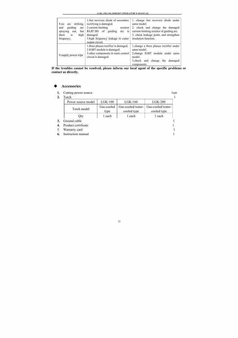
8.no arc striking,
and guiding arc
spraying out, but
there is high
frequency.
1.fast recovery diode of secondary
rectifying is damaged.
2.current-limiting resistor
R6,R7,R8 of guiding arc is
damaged.
3.high frequency leakage in cutter
output circuit.
1. change fast recovery diode under
same model.
2. check and change the damaged
current-limiting resistor of guiding arc.
3. check leakage point, and strengthen
insulation function.
9.supply power trips
1.three phases rectifier is damaged.
2.IGBT module is damaged.
3.other components in main control
circuit is damaged.
1.change a three phases rectifier under
same model.
2.change IGBT module under same
model.
3.check and change the damaged
components.
If the troubles cannot be resolved, please inform our local agent of the specific problems or
contact us directly.
Accessories
1. Cutting power source 1set
2. Torch 1
Power source model LGK-100 LGK-160 LGK-200
Torch modelGas-cooled
type
Gas-cooled/water-
cooled type
Gas-cooled/water-
cooled type
Qty 1 each 1 each 1 each
3. Ground cable 1
4.
Product certificate 1 5. Warranty card 1
6. Instruction manual 1
8/20/2019 Lgk Igbt Manual
http://slidepdf.com/reader/full/lgk-igbt-manual 24/25

8/20/2019 Lgk Igbt Manual
http://slidepdf.com/reader/full/lgk-igbt-manual 25/25
The final explanation right is reserved to Huayuan Company!
If there is any change in the manual, please forgive not to inform separately!
Address: Wuhou National Science Park, Chengdu, China
Postcode: 610045
Tel: 0086-28-85012443, 85011951, 85013964
Fax: 0086-28-85033444
E-mail: [email protected]
http://www.hwayuan.com


