+ All Categories
Home > Documents > LHC-MKI (Injection Kicker Magnet) Impedance Simulations ... fileThe LHC-MKI is a very complex...

LHC-MKI (Injection Kicker Magnet) Impedance Simulations ... fileThe LHC-MKI is a very complex...

Date post: 06-May-2019
Category:
Upload: danghanh
View: 218 times
Download: 0 times
Share this document with a friend
19
Introduction Simulations Heating Estimates Summary LHC-MKI (Injection Kicker Magnet) Impedance Simulations - Update and Summary H. Day, B. Salvant, M. Barnes, E. Metral, F. Caspers January 25, 2012 H. Day, B. Salvant, M. Barnes, E. Metral, F. Caspers LHC-MKI (Injection Kicker Magnet) Impedance Simulations - Upda
Transcript

IntroductionSimulations

Heating EstimatesSummary

LHC-MKI (Injection Kicker Magnet)Impedance Simulations - Update and

Summary

H. Day, B. Salvant, M. Barnes, E. Metral, F. Caspers

January 25, 2012

H. Day, B. Salvant, M. Barnes, E. Metral, F. Caspers LHC-MKI (Injection Kicker Magnet) Impedance Simulations - Update and Summary

IntroductionSimulations

Heating EstimatesSummary

IntroductionHeating Measurements

Introduction

Background - During the 2011 run heating and pressure increaseswere noted in the LHC-MKI which could be attributed tobeam-induced heating. Required to reevaluate the impedancemodel of the LHC-MKI and past heating estimatesAIM:

To acquire a simulation model of the LHC-MKI that reproduces theresults of existing coaxial wire measurements

To use the simulation model to obtain heating estimates for theLHC-MKI using diffierent beam screen configurations

To examine alternative beam screen designs to see if they improvethe heating situation

H. Day, B. Salvant, M. Barnes, E. Metral, F. Caspers LHC-MKI (Injection Kicker Magnet) Impedance Simulations - Update and Summary

IntroductionSimulations

Heating EstimatesSummary

IntroductionHeating Measurements

MKIs: steady temperature increase over 2011

8 April 1st 2011 October 31st 2011

MKI in point 8

MKI in point 2

60 °C

20 °C

60 °C

20 °C

MKI8-D

MKI8-B

All MKIs are getting hotter…

40 °C

40 °C

…but MKI-8D and MKI-8B are a factor ~2 off

Figure 1: From B. Salvant’s talk Evian Workshop, 2011H. Day, B. Salvant, M. Barnes, E. Metral, F. Caspers LHC-MKI (Injection Kicker Magnet) Impedance Simulations - Update and Summary

IntroductionSimulations

Heating EstimatesSummary

Simulation ModelDesign SchematicsSimulation ModelsImpedance Results

LHC-MKI Structure

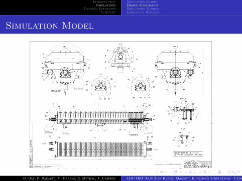
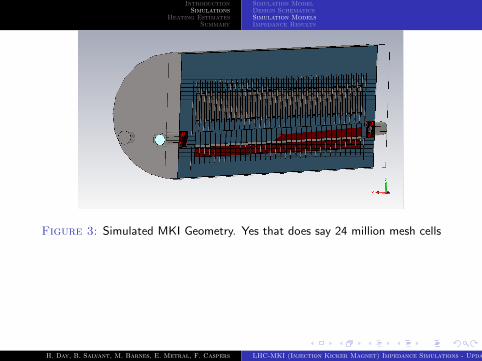
The LHC-MKI is a very complex internal structure (See Fig. 2).

Some 3m of transmission line kicker magnet, with componentsvarying in scale from order of metres to tenths of a millimetre - Verydifficult to mesh properly

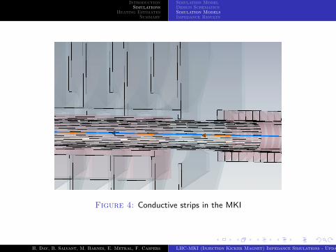
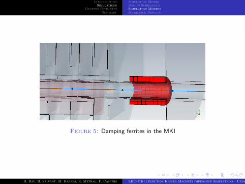
Structure has a mixture of resistive wall impedances (ferrite blocks)and cavity-like impedances (vacuum tank and conductive strips) -integrated wakelength must be long to correctly evaluate both(integrated wakelength of 15m used for all simulations)

H. Day, B. Salvant, M. Barnes, E. Metral, F. Caspers LHC-MKI (Injection Kicker Magnet) Impedance Simulations - Update and Summary

IntroductionSimulations

Heating EstimatesSummary

Simulation ModelDesign SchematicsSimulation ModelsImpedance Results

Simulation Model

Figure 2: The schematics of the LHC-MKIH. Day, B. Salvant, M. Barnes, E. Metral, F. Caspers LHC-MKI (Injection Kicker Magnet) Impedance Simulations - Update and Summary

IntroductionSimulations

Heating EstimatesSummary

Simulation ModelDesign SchematicsSimulation ModelsImpedance Results

Figure 3: Simulated MKI Geometry. Yes that does say 24 million mesh cells

H. Day, B. Salvant, M. Barnes, E. Metral, F. Caspers LHC-MKI (Injection Kicker Magnet) Impedance Simulations - Update and Summary

IntroductionSimulations

Heating EstimatesSummary

Simulation ModelDesign SchematicsSimulation ModelsImpedance Results

Figure 4: Conductive strips in the MKI

H. Day, B. Salvant, M. Barnes, E. Metral, F. Caspers LHC-MKI (Injection Kicker Magnet) Impedance Simulations - Update and Summary

IntroductionSimulations

Heating EstimatesSummary

Simulation ModelDesign SchematicsSimulation ModelsImpedance Results

Figure 5: Damping ferrites in the MKI

H. Day, B. Salvant, M. Barnes, E. Metral, F. Caspers LHC-MKI (Injection Kicker Magnet) Impedance Simulations - Update and Summary

IntroductionSimulations

Heating EstimatesSummary

Simulation ModelDesign SchematicsSimulation ModelsImpedance Results

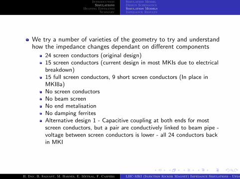
We try a number of varieties of the geometry to try and understandhow the impedance changes dependant on different components

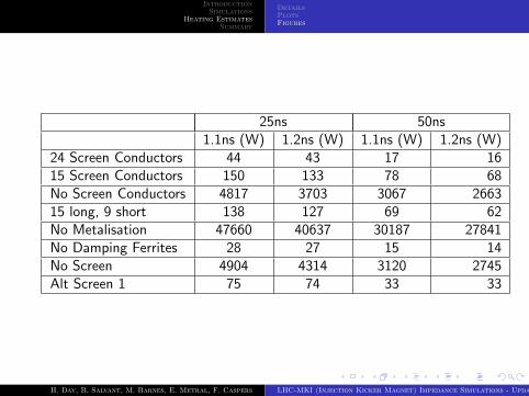
24 screen conductors (original design)15 screen conductors (current design in most MKIs due to electricalbreakdown)15 full screen conductors, 9 short screen conductors (In place inMKI8a)No screen conductorsNo beam screenNo end metalisationNo damping ferritesAlternative design 1 - Capacitive coupling at both ends for mostscreen conductors, but a pair are conductively linked to beam pipe -voltage between screen conductors is lower - all 24 conductors backin MKI

H. Day, B. Salvant, M. Barnes, E. Metral, F. Caspers LHC-MKI (Injection Kicker Magnet) Impedance Simulations - Update and Summary

IntroductionSimulations

Heating EstimatesSummary

Simulation ModelDesign SchematicsSimulation ModelsImpedance Results

0 500 1000 1500 2000 2500 3000 3500Frequency (MHz)

10-6

10-5

10-4

10-3

10-2

10-1

100

101

102

103

104

Real Lo

ngit

udin

al Im

pedance

)

No Metalisation15 Conductive Strips24 Conductive Strips15 long, 9 shortNo Conductive StripsNo Damping FerritesNo ScreenAlt Screen 1

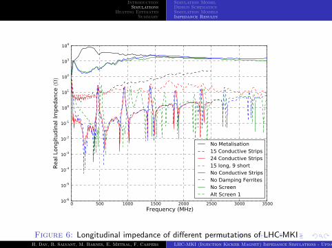
Figure 6: Longitudinal impedance of different permutations of LHC-MKIH. Day, B. Salvant, M. Barnes, E. Metral, F. Caspers LHC-MKI (Injection Kicker Magnet) Impedance Simulations - Update and Summary

IntroductionSimulations

Heating EstimatesSummary

Simulation ModelDesign SchematicsSimulation ModelsImpedance Results

0 500 1000 1500 2000 2500 3000 3500Frequency (MHz)

0

50

100

150

200

250

Real Lo

ngit

udin

al Im

pedance

)

15 Conductive Strips24 Conductive Strips15 long, 9 shortNo Damping FerritesAlt Screen 1

Figure 7: Focus of longitudinal impedance of realistic setups of LHC-MKI

H. Day, B. Salvant, M. Barnes, E. Metral, F. Caspers LHC-MKI (Injection Kicker Magnet) Impedance Simulations - Update and Summary

IntroductionSimulations

Heating EstimatesSummary

Simulation ModelDesign SchematicsSimulation ModelsImpedance Results

Comparison to Measurements

0 500 1000 1500 2000 2500Frequency (MHz)

0

5

10

15

20

25

30

35

40R

eal Lo

ngit

udin

al Im

pedance

)24 Conductive StripsMeasurement 24 conductors

Figure 8: Comparison between simulations and measurements of the MKIwith 24 screen conductors

H. Day, B. Salvant, M. Barnes, E. Metral, F. Caspers LHC-MKI (Injection Kicker Magnet) Impedance Simulations - Update and Summary

IntroductionSimulations

Heating EstimatesSummary

Simulation ModelDesign SchematicsSimulation ModelsImpedance Results

0 500 1000 1500 2000 2500Frequency (MHz)

0

50

100

150

200

250

Real Lo

ngit

udin

al Im

pedance

)

15 Conductive StripsMeasurement 15 conductors

Figure 9: Comparison between simulations and measurements of the MKIwith 15 screen conductors

H. Day, B. Salvant, M. Barnes, E. Metral, F. Caspers LHC-MKI (Injection Kicker Magnet) Impedance Simulations - Update and Summary

IntroductionSimulations

Heating EstimatesSummary

Simulation ModelDesign SchematicsSimulation ModelsImpedance Results

Figure 10: Comparison between simulations and measurements of the MKIwith 15 long and 9 short screen conductors

H. Day, B. Salvant, M. Barnes, E. Metral, F. Caspers LHC-MKI (Injection Kicker Magnet) Impedance Simulations - Update and Summary

IntroductionSimulations

Heating EstimatesSummary

DetailsPlotsFigures

Heating Estimates

All heating estimates are done with nominal LHC bunch parameters(bunch population Nb = 1.15 × 10¹¹)

For 50ns spacing number of bunches nbunches = 1368, for 25nsnbunches = 2808

Power loss is quadratic with bunch population

We assume a parabolic bunch distribution for these estimates

Due to the broadband nature of the impedances the estimates usinga cos2 and measured spectra are similar to those from parabolicestimates

H. Day, B. Salvant, M. Barnes, E. Metral, F. Caspers LHC-MKI (Injection Kicker Magnet) Impedance Simulations - Update and Summary

IntroductionSimulations

Heating EstimatesSummary

DetailsPlotsFigures

0.4 0.6 0.8 1.0 1.2 1.4 1.6Bunch Length (s) 1e 9

101

102

103

104

105

Pow

er

Loss

in t

he L

HC

-MK

I (W

)

24 Screen Conductors15 Screen ConductorsNo Screen Conductors15 long, 9 shortNo MetalisationNo Damping FerritesNo ScreenAlt Screen 1

Figure 11: Heating estimates for 25ns bunch spacing

H. Day, B. Salvant, M. Barnes, E. Metral, F. Caspers LHC-MKI (Injection Kicker Magnet) Impedance Simulations - Update and Summary

IntroductionSimulations

Heating EstimatesSummary

DetailsPlotsFigures

0.4 0.6 0.8 1.0 1.2 1.4 1.6Bunch Length (s) 1e 9

101

102

103

104

105

Pow

er

Loss

in t

he L

HC

-MK

I (W

)24 Screen Conductors15 Screen ConductorsNo Screen Conductors15 long, 9 shortNo MetalisationNo Damping FerritesNo ScreenAlt Screen 1

Figure 12: Heating estimates for 50ns bunch spacing

H. Day, B. Salvant, M. Barnes, E. Metral, F. Caspers LHC-MKI (Injection Kicker Magnet) Impedance Simulations - Update and Summary

IntroductionSimulations

Heating EstimatesSummary

DetailsPlotsFigures

25ns 50ns1.1ns (W) 1.2ns (W) 1.1ns (W) 1.2ns (W)

24 Screen Conductors 44 43 17 1615 Screen Conductors 150 133 78 68No Screen Conductors 4817 3703 3067 266315 long, 9 short 138 127 69 62No Metalisation 47660 40637 30187 27841No Damping Ferrites 28 27 15 14No Screen 4904 4314 3120 2745Alt Screen 1 75 74 33 33

H. Day, B. Salvant, M. Barnes, E. Metral, F. Caspers LHC-MKI (Injection Kicker Magnet) Impedance Simulations - Update and Summary

IntroductionSimulations

Heating EstimatesSummary

Summary

We have shown that we can successfully simulate the full structureof a large kicker magnet (and other devices)

Having heating estimates - We can show that the screen is definitelyneeded, and a screen with 24 conductors is better than with fewer

Atleast one alternative beam screen gives better performance thanexisting solutions

Other designs to be investigated. Also would like to extend themodel to include RF fingers at interconnects

H. Day, B. Salvant, M. Barnes, E. Metral, F. Caspers LHC-MKI (Injection Kicker Magnet) Impedance Simulations - Update and Summary


Recommended