Carl R R. Frank 202.719.7269 [email protected]1776 K STREET NW WASHINGTON, DC 20006 PHONE 202.719.7000 FAX 202.719.7049 Virginia Office 7925 JONES BRANCH DRIVE SUITE 6200 McLEAN, VA 22102 PHONE 703.905.2800 FAX 703.905.2820 www.wrf.com March 29, 2006 Ms. Marlene H. Dortch Secretary Federal Communications Commission 445 - 12th Street, SW Washington, DC 20554 Re: Sirius Satellite Radio Inc. In re: Applications for Transfer of Control of Licensee WCS Wireless License Subsidiary, LLC from WCS Wireless, Inc. to XM Satellite Radio Holdings Inc. – File No. 0002240823, DA 05-1662, WT Docket No. 05-256 Biennial Regulatory Review – Amendment of Parts 1, 22, 24, 27, and 90 to Streamline and Harmonize Various Rules Affecting Wireless Radio Services, WT Docket No. 03-264 Establishment of Rules and Policies for the Digital Audio Radio Satellite Service in the 2310-2360 MHz Frequency Band, IB Docket No. 95-91 Dear Ms. Dortch: On March 28, 2006, representatives from Sirius Satellite Radio Inc. (“Sirius”) held three separate meetings with the staffs of the International Bureau, the Office of Engineering and Technology and the Wireless Telecommunications Bureau principally to discuss the above-captioned proceedings, and specifically to discuss the proposed transaction involving XM Satellite Radio Holdings Inc. (“XM”) and WCS Wireless, Inc. The participants in each of the three meetings are identified below. During these meetings, Sirius presented to the staff the attached White Paper, which describes the nature and extent of the radio interference that threatens the Satellite Digital Audio Radio Service (SDARS). Among other issues, the White Paper describes and analyzes three interference sources: 1) multi-carrier third order intermodulation interference involving XM’s terrestrial repeaters and WCS base transmitters; 2) single-carrier induced overload interference from either XM’s terrestrial repeaters or certain WCS base transmitters; and, 3) out-of-band emissions from WCS transmitters.
Ms. Marlene H. Dortch Secretary Federal Communications Commission 445 - 12th Street, SW Washington, DC 20554 Re: Sirius Satellite Radio Inc.
In re: Applications for Transfer of Control of Licensee WCS Wireless License Subsidiary, LLC from WCS Wireless, Inc. to XM Satellite Radio Holdings Inc. – File No. 0002240823, DA 05-1662, WT Docket No. 05-256
Biennial Regulatory Review – Amendment of Parts 1, 22, 24, 27, and 90 to Streamline and Harmonize Various Rules Affecting Wireless Radio Services, WT Docket No. 03-264 Establishment of Rules and Policies for the Digital Audio Radio Satellite Service in the 2310-2360 MHz Frequency Band, IB Docket No. 95-91
Dear Ms. Dortch:
On March 28, 2006, representatives from Sirius Satellite Radio Inc. (“Sirius”) held three separate meetings with the staffs of the International Bureau, the Office of Engineering and Technology and the Wireless Telecommunications Bureau principally to discuss the above-captioned proceedings, and specifically to discuss the proposed transaction involving XM Satellite Radio Holdings Inc. (“XM”) and WCS Wireless, Inc. The participants in each of the three meetings are identified below. During these meetings, Sirius presented to the staff the attached White Paper, which describes the nature and extent of the radio interference that threatens the Satellite Digital Audio Radio Service (SDARS). Among other issues, the White Paper describes and analyzes three interference sources: 1) multi-carrier third order intermodulation interference involving XM’s terrestrial repeaters and WCS base transmitters; 2) single-carrier induced overload interference from either XM’s terrestrial repeaters or certain WCS base transmitters; and, 3) out-of-band emissions from WCS transmitters.
March 29, 2006 Page 2
As previously discussed by Sirius, the occurrence of intermodulation interference is directly related to the co-location of XM terrestrial repeaters with WCS transmitters. Because there is great probability that XM will co-locate its SDARS terrestrial repeaters with WCS base transmitters if it is allowed to acquire the WCS licenses of WCS Wireless, Inc., the Sirius interference analysis is highly relevant to that proposed transaction. In presenting the report to the staff, Sirius stated that the White Paper is an attempt to benchmark both the existing and predicted levels of interference to SDARS receivers. Sirius further stated that in the near future it intends to provide the staff with recommendations for rule changes to establish power flux density limits on both WCS and SDARS terrestrial transmitters in order to minimize interference levels across the entire 2.3 GHz band. Please contact the undersigned with any questions regarding this matter. Very truly yours, __/s/ Carl R. Frank_____ Carl R. Frank
Attachments cc: Meeting Participants
March 29, 2006 Page 3
Meeting 1: International Bureau Roderick Porter Richard Engleman Robert Nelson Gardner Foster Steve Duall Rosalie Chiara (MMB) Meeting 2: Office of Engineering and Technology Julius Knapp Alan Scrime Harry Wong Meeting 3: Wireless Telecommunications Bureau David Furth Cathleen Massey Katherine Harris Mike Ferrante Zenji Nakazawa Moslem Sawez Tom Derenge Sirius Satellite Radio (all meetings) Terrence Smith, Senior VP Engineering Robert Briskman, Co-Founder Alan Pate, Director of Terrestrial Systems Terry Donnelly, General Counsel Michael Rhodes (Cavell, Mertz & Davis, Inc. Consulting Engineers) Carl Frank, Wiley Rein & Fielding Michael Lewis, Wiley Rein & Fielding
___________________
White Paper
Interference to the SDARS Service from WCS Transmitters
Prepared by
Cavell, Mertz & Davis, Inc. Consulting Engineers 1
and Sirius Satellite Radio Engineering 2
March 28, 2006
1 7839 Ashton Avenue, Manassas, VA 20109. Tel: (703) 392-9090 2 1221 Avenue of the Americas, 36th Floor, New York, NY 10020. Tel: (212) 584-5100
Table of Contents 1 Executive Summary ................................................................................................................ 3 2 Introduction............................................................................................................................. 4 3 Background and Overview of the WCS and SDARS Spectrum Allocations ......................... 5 4 Assessment of impacts of Interference Mechanisms .............................................................. 8
4.1 Multi-carrier Induced Intermodulation Interference............................................................. 8 4.1.1 Measurements of 3rd order inter-modulation interference .................................... 10 4.1.2 Impact assessment of inter-modulation interference ............................................ 11
4.2 Single-carrier induced signal overload interference ........................................................... 13 4.2.1 Measurements of overload interference................................................................ 13 4.2.2 Impact assessment of overload interference ......................................................... 14
4.3 Investigation of out-of-band emissions interference........................................................... 16 4.3.1 Current WCS Rules Governing Out-of-Band Emissions...................................... 16 4.3.2 Relationship of Current Rules to Receiver Blanketing Interference .................... 17
5 Examples of interference impacts to Sirius service in major markets .................................. 18 5.1 Washington, DC Market ..................................................................................................... 18 5.2 Philadelphia, PA Market..................................................................................................... 25
6 Newer RF Filter Technology Will Not Eliminate the Interference ...................................... 32 6.1 SAW filter performance analysis........................................................................................ 32 6.2 BAW filter performance analysis ....................................................................................... 35 6.3 Filter technology Summary................................................................................................. 36
7 Discussion of SDARS interoperability operation................................................................. 37 8 Summary and Conclusions ................................................................................................... 37 9 Appendix............................................................................................................................... 39
9.1 Multiple Interferer Test Setup............................................................................................. 39 9.2 Single Interferer Test Setup ................................................................................................ 41
Technical White Paper - Interference to the SDARS Service from WCS Transmitters 2
1 Executive Summary The Wireless Communications Service (WCS) and the Satellite Digital Audio Radio Service (SDARS or satellite DARS) are allocated the use of adjacent frequencies. This arrangement creates the risk that WCS transmitters will interfere with the reception of low-power satellite-based SDARS broadcasts. These risks were understood when the Federal Communications Commission (FCC) adopted this allocation plan. To minimize the potential for interference, the FCC imposed stringent out-of-band emission limitations on WCS transmitters and generally required WCS licensees to use technical means to resolve other types of interfering signals. WCS licensees have yet to deploy operational systems. As a result, the effectiveness of these provisions has not been tested. This is likely to soon change since the 10-year construction deadline for most WCS licensees expires in 2007. XM Satellite Radio Holdings, Inc. (“XM”) is now seeking regulatory approval to utilize WCS frequencies for “broadcast-like” services. This will certainly increase the potential for interference to satellite DARS subscribers, a possibility the FCC did not consider. That makes increased interference a direct consequence of the merger. This White Paper examines interference to Sirius Satellite Radio (“Sirius”) from collocated XM/WCS terrestrial transmitters; from wide scale deployment of WCS base stations in adjacent spectrum; and from XM’s existing repeater network. Subscribers to Sirius’ service face two predominant interference mechanisms:
• Intermodulation interference (“third order intermod” or “IM3”) caused by the interaction of WCS and SDARS terrestrial transmitters. While not releasing specifics, XM makes no secret of its WCS network deployment plans. As Wall Street analysts have emphasized, the post-acquisition XM will “leverage” its existing terrestrial network by collocating new WCS transmitters at or near its present satellite DARS repeaters. On average, Sirius receivers can expect to receive interference substantial enough to cause loss of service when located within a 3.7 square kilometers area surrounding interfering transmitter sites.
• Brute-force overload interference caused by nearby satellite DARS repeaters as well as
WCS base transmitters. With a terrestrial network nearly 10 times larger than Sirius, several XM repeaters today generate ground-level “dead zones” – muting reception of the Sirius satellite signal. A WCS C-Block transmitter would perform similarly, overpowering Sirius satellite transmissions in areas averaging 6.1 square kilometers.
Each calculated “mute area” would explode up to forty-fold if the FCC approves XM’s recent request to modify WCS transmitter power requirements. And, additional receiver filtering is no panacea for eliminating such interference.
Technical White Paper - Interference to the SDARS Service from WCS Transmitters 3
This White Paper calculates the potential aggregate interference areas using XM’s actual deployment in two specific markets. In the Washington, DC market, for example, the aggregate level of interference from collocation and other WCS/XM interference sources would be as great as 625 square kilometers. As a minimum, the FCC should condition XM’s acquisition of any WCS licenses to prevent collocation of WCS/SDARS transmitters that result in intermodulation interference to other licensees in the 2.3 GHz band. Looking ahead, this is the time to address these threats before they become widespread. A long-term solution requires re-opening the rulemaking proceeding on SDARS terrestrial repeaters, with an additional mandate to update WCS technical rules. Sirius recommends the agency impose power flux density limit for both WCS and terrestrial SDARS transmitters. This would reduce interfering signal levels “on the street” where consumer SDARS and, presumably, WCS receivers typically operate. Further, given the rapid growth of the SDARS customer base, the FCC must provide a streamlined process for review of any interference complaints due to the introduction of WCS transmitters. Today, Sirius has over four million subscribers, and on average over eight million people listen to its broadcasts every day. Satellite radio is one of the fastest growing entertainment services in the nation; since Christmas Day 2005 alone, more than 1,000,000 people have subscribed to Sirius. Sirius offers consumer a wide variety of choice in entertainment, and is expected to be a great platform for our civil emergency warnings and other Homeland Security applications. Satellite radio should be nourished as one of our national assets. The FCC should make every effort to ensure that Sirius subscribers can enjoy the service free from interference from other spectrum holders and the Sirius service is permitted to flourish.
2 Introduction The purpose of this White Paper is to quantify the significant impact to satellite DARS in general, and Sirius service in particular, caused by WCS interference sources. FCC approval of XM’s application to acquire certain WCS licenses3 would exacerbate the interference’s impact and extent,4 particularly given the interference Sirius already experiences as a result of XM’s current operations. Further, XM’s recent and repeated request for up to a 40-fold increase in EIRP limits for the 2.3 GHz WCS band could undermine the SDARS service completely.5
3 See Wireless Telecommunications Bureau Assignment of License Authorization Applications, Transfer of Control of Licensee Applications, and De Facto Transfer Lease Applications Accepted for Filing, Public Notice, Report No.2209 (rel. July 20, 2005) (Public Notice announcing that XM-WCS transfer of control application has been accepted for filing). The XM-WCS application has been assigned WTB Docket No. 05-256. 4 See, e.g. Joint Reply Comments of WCS Wireless LLC and XM Satellite Radio Holdings, Inc., WT Docket No. 03-264 (filed Jan. 17, 2006). Previous submissions have illustrated the serious impact that co-location of WCS transmitters with XM SDARS transmitters would have under the existing WCS rules. 5 In the matter of Biennial Regulatory Review-Amendment of Parts 1, 22, 24, 27, and 90 to Streamline and Harmonize Various Rules Affecting Wireless Radio Services, Letter of Sirius Satellite Radio, WT Docket No. 03-264 (February 13, 2006).
Technical White Paper - Interference to the SDARS Service from WCS Transmitters 4
The satellite DARS repeater rulemaking has been stalled for nine years. As for WCS, no WCS system in the contiguous United States is in commercial operations – there is no “installed base” potentially stranded by rule changes, making this the last opportunity for amendment without significant financial penalties. Moreover, new rules founded in part on street-level signal density would foster deployment of more advanced and more effective networks in the 2305-2320 MHz and 2345-2360 MHz WCS bands. This paper will assess the threat from dual-carrier and multi-carrier induced inter-modulation interference on SDARS satellite reception. Signal overload is another significant interference mechanism when examining the operation of both the WCS and SDARS service. This is due in large part to the high power levels that can exist in channels directly adjacent to spectrum utilized for relatively weak satellite power signals. The absence of any guard band between these high power terrestrial signals and much lower power satellite signals eliminates any opportunity for effective receiver filtering to alleviate this interference mechanism. Unfortunately, the present WCS out-of-band emission limits do not resolve the problem, as they are both overly strict and under-inclusive. This paper calculates the effects of each such interference in terms of population and subscriber impact, using XM’s actual deployment in the markets of Washington, DC and Philadelphia.
3 Background and Overview of the WCS and SDARS Spectrum Allocations
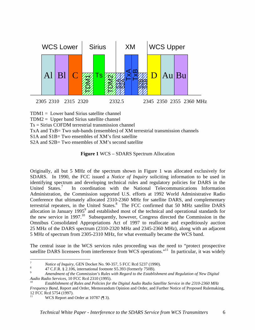
The WCS and SDARS services occupy 55 MHz of spectrum from 2305 MHz to 2360 MHz. The WCS service consists of six blocks of 5 MHz each, in the 2305-2320 MHz and 2345-2360 MHz bands. As shown in the following figure, there are paired blocks (A lower + A upper; B lower + B upper) that have been allocated on a regional basis (MEA service areas) and unpaired blocks (C and D) that have been allocated over very wide service areas (REAGs).6 The SDARS service occupies the center 25 MHz (2320-2345 MHz) and is divided evenly between the two licensees, Sirius (2320-2332.5 MHz) and XM (2332.5-2345 MHz).
6 Amendment of the Commission’s Rules to Establish Part 27, the Wireless Communications Service (“WCS”), 12 FCC Rcd 10785, 10808 ¶ 45 (1997) (“WCS Report and Order”).
Technical White Paper - Interference to the SDARS Service from WCS Transmitters 5
BlAl C D Au BuTD
M1
TDM
2Ts
S1A Tx
A
2305 2310 2315 2320 2345 2350 2355 23602332.5
Sirius XM
MHz
S2A
S2B
S1BTx
B
WCS Lower WCS Upper
TDM1 = Lower band Sirius satellite channel TDM2 = Upper band Sirius satellite channel Ts = Sirius COFDM terrestrial transmission channel TxA and TxB= Two sub-bands (ensembles) of XM terrestrial transmission channels S1A and S1B= Two ensembles of XM’s first satellite S2A and S2B= Two ensembles of XM’s second satellite
Figure 1 WCS – SDARS Spectrum Allocation
Originally, all but 5 MHz of the spectrum shown in Figure 1 was allocated exclusively for SDARS. In 1990, the FCC issued a Notice of Inquiry soliciting information to be used in identifying spectrum and developing technical rules and regulatory policies for DARS in the United States.7 In coordination with the National Telecommunications Information Administration, the Commission supported U.S. efforts at 1992 World Administrative Radio Conference that ultimately allocated 2310-2360 MHz for satellite DARS, and complementary terrestrial repeaters, in the United States.8 The FCC confirmed that 50 MHz satellite DARS allocation in January 19959 and established most of the technical and operational standards for the new service in 1997.10 Subsequently, however, Congress directed the Commission in the Omnibus Consolidated Appropriations Act of 1997 to reallocate and expeditiously auction 25 MHz of the DARS spectrum (2310-2320 MHz and 2345-2360 MHz), along with an adjacent 5 MHz of spectrum from 2305-2310 MHz, for what eventually became the WCS band. The central issue in the WCS services rules proceeding was the need to “protect prospective satellite DARS licensees from interference from WCS operations.”11 In particular, it was widely 7 Notice of Inquiry, GEN Docket No. 90-357, 5 FCC Rcd 5237 (1990). 8 47 C.F.R. § 2.106, international footnote S5.393 (formerly 750B). 9 Amendment of the Commission’s Rules with Regard to the Establishment and Regulation of New Digital Audio Radio Services, 10 FCC Rcd 2310 (1995). 10 Establishment of Rules and Policies for the Digital Audio Radio Satellite Service in the 2310-2360 MHz Frequency Band, Report and Order, Memorandum Opinion and Order, and Further Notice of Proposed Rulemaking, 12 FCC Rcd 5754 (1997). 11 WCS Report and Order at 10787 (¶ 3).
Technical White Paper - Interference to the SDARS Service from WCS Transmitters 6
understood that the allocation to WCS spectrum immediately adjacent to the relatively low-powered satellite DARS would pose significant risks for cross-service interference. After satellite DARS applicants’ comments demonstrated the inadequacy of the FCC’s proposed out-of-band emission limits for the WCS, the Commission amended the limits to “ensure that WCS operations do not cause harmful interference or disturbance to adjacent satellite DARS reception.”12 In their final form, those limits remain applicable.13 The same rules also took note of the potential for WCS systems to generate inter-modulation interference, and so urged WCS licensees to resolve such interference via “technical” (i.e., not regulatory) means.14 But the FCC understood these regulations might fall short, and so cautioned:
If the FCC determines, however, that interference which significantly interrupts or degrades a radio service is being caused, it may, after notice and an opportunity for a hearing, require modifications to any WCS station as necessary to eliminate such interference.15
To emphasize the point, the agency specifically advised potential WCS licensees that the spectrum was subject to any service limitations stemming from the more stringent limit.16 Moreover, in 1997, the Commission warned potential WCS bidders to “consider carefully whether their anticipated uses and business plans can be successfully implemented” within the technical limits, explaining that “wide area, full mobility systems and service such as those being provided or anticipated in the cellular and PCS bands are likely to be of questionable feasibility.”17 Put differently, WCS licensees purchased their spectrum rights with full knowledge of these restrictions. In fact, in part due to these constraints, WCS licensees acquired their spectrum at a substantial discount compared with DARS providers.18
Since adopting these rules, the FCC has developed a record on potential interference from terrestrial SDARS repeaters into WCS receivers.19
12 Id. at 10854 (¶ 136). 13 47 C.F.R. § 27.53. 14 Id., § 27.54(c). 15 Id., § 27.54. 16 For example, the FCC noted that the limits could make mobile operations in the WCS spectrum “technologically infeasible.” WCS Report and Order at 10787 (¶ 3). 17 Amendment of the Commission’s Rules to Establish Part 27, the Wireless Communications Services (“WCS”), Memorandum Opinion and Order, 12 FCC Rcd 3977, 3979 (1997). 18 FCC Announces Auction Winners for Digital Audio Radio Service, 12 FCC Rcd 18727, 18727 (1997) (Public Notice) (noting that the satellite DARS licensees Satellite CD Radio, Inc. and American Mobile Radio Corporation paid $83,346,000.00 and $89,888,888.00, respectively); WCS Auction Closes Winning Bidders in the Auction of 128 Wireless Communications Service Licenses, 12 FCC Rcd 21653, 21653 (1997) (Public Notice) (noting that the WCS auction raised a net total of $13,638,940.00). 19 See, Applications for Transfer of Control of Licensee WCW Wireless License Subsidiary, LLC from WCS Wireless, Inc. to XM Satellite Radio Holdings Inc., et al, Sirius Satellite Radio Inc. Notice of Ex Parte Presentation, File No. 0002240823 (DA 05-1662), (February, 24, 2006).
Technical White Paper - Interference to the SDARS Service from WCS Transmitters 7
4 Assessment of impacts of Interference Mechanisms In the design of SDARS frequency plans, both Sirius and XM transmit their terrestrial based signals in the center of their allocated spectrum, thereby creating a guard band that affords some level of protection to one system’s satellite signal from the other system’s terrestrial based signal. No such protection exists between SDARS satellite signals and WCS spectrum. WCS and SDARS band spectrum allocation is unique in that high power terrestrial-based broadcasts are permitted to be transmitted in spectrum directly adjacent to relatively low power SDARS satellite signals. See note 9, supra. The lack of any established guard band between WCS and SDARS spectrum creates enormous service planning concerns for the SDARS systems on an interference basis. While DARS antenna modules have sufficient frequency selectivity to reject interference from PCS and ISM services, the WCS spectrum is directly adjacent to DARS services and represent a much more difficult issue for filtering technology to address. As detailed in Section 6, the current state-of-the-art filter designs suffer from combinations of high pass band insertion loss, very high pass band amplitude ripple, frequency selectivity and manufacturing tolerances for temperature drift that obviate their utility in addressing this interference. The following sections consider the negative effects of various interference mechanisms on SDARS with actual test results and service impact estimations. The discussion in Section 4.1 focuses on 3rd order intermodulation effects caused by XM and WCS transmitters. Sections 4.2 focuses on the effects caused by overload interference and Section 4.3 focuses on out-of-band emission limits for WCS transmissions. For each mechanism, receiver measurements were conducted to determine interference levels that could be tolerated before service is impacted. In practice more than one interference mechanism will contribute to loss of service. When possible, the dominant mechanism will be identified with the various test results described below.
4.1 Multi-carrier Induced Intermodulation Interference This section focuses on multi-carrier induced intermodulation interference effects caused by XM and WCS transmitters. Using receiver measurements in the laboratory, the level of interference that causes service interruption was determined. The multi-carrier induced inter-modulation interference occurs in the receiver’s tuner, when multiple high-powered unwanted signals from different transmitting sources are present in the aggregate received signal. This interference mechanism is well characterized, and readily calculable via known mathematical relationships. When these strong signals with the appropriate mathematical relationship are presented to a receiver, they cause the active elements, usually in the input stages of the receiver, to operate in a non-linear manner. The incoming undesired signals mix in the receiver and produce a third (or higher-order) frequency – an intermodulation product – which can fall on or near the desired frequency of the receiver. If the resultant intermodulation product generated in the first stages of
Technical White Paper - Interference to the SDARS Service from WCS Transmitters 8
the receiver is sufficiently strong, it can effectively block the incoming signal (by excessively raising the in-band noise floor of the desired signal). This would render the receiver unusable at that location. Note that this interference is typical in receivers and cannot be cured by filtering at the transmitter as it is generated within the receiver. If the interference sources (F1 and F2) are sufficiently close to the desired signal band frequency, limiting the levels of the interference at the receiver input (prior to the creation of the inter-modulation products) is extremely difficult with practical filtering technologies; as the filter must simultaneously pass the desired signal and reject nearby multiple interference signals. As the commission has noted,20 the concept of mixing occurring in non-linear devices is sometimes analogized to color mixture. Thus, if a receiver were presented with a strong “blue” XM Terrestrial signal and a strong “yellow” WCS D-Block signal, the two colors could mix in the first stage of the Sirius receiver and form an interfering “green” signal that fell within the Sirius SDARS spectrum. The “mixing” concept is important to the understanding of intermodulation interference because it explains how two or more signals, separated in frequency from the Sirius band can still generate interference. In practice, intermodulation products are categorized according to “order” and can result from the interaction of two or more frequencies. For example, in the case of third-order, two-frequency (F1 and F2) intermodulation, the intermodulation products (P) can be calculated by: Pintermod = 2F1-F2 and Pintermod = 2F2-F121. The most significant multi-carrier induced interference into the Sirius SDARS band can be identified as the third-order intermodulation products from the following XM and WCS terrestrial bands:
1. The mixing of the XM COFDM repeater carrier (at 2338.75 MHz) and the WCS D-Block carrier (at 2347.5 MHz) falls into the Sirius TDM2 satellite band (at 2330 MHz) following the formula 2 x 2338.75 MHz – 2347.5 MHz = 2330 MHz.
2. The mixing of the XM COFDM repeater carrier (at 2338.75 MHz) and the WCS B-upper Block carrier (at 2357.5 MHz) falls into the Sirius TDM1 satellite band (at 2320 MHz) following the formula 2 x 2338.75 MHz – 2357.5 MHz = 2320 MHz.
There is no effective way through filtering to remove the inter-modulation products that fall within a desired frequency band as the receiver is unable to distinguish between the desired and undesired signals. The 3rd order products typically dictate the fundamental linearity
20 See Improving Public Safety Communications in the 800 MHz Band, Report and Order, 19 FCC Rcd 14969, 15023 (2004). 21 Fifth-order, two-frequency intermodulation products are calculated by: Pintermod = 3F1-2F2 and Pintermod = 3F2-2F1. Intermodulation products can also be generated by interaction of three or more transmitters, for example, some third-order, three frequency (F1, F2 and F3) intermodulation products can be calculated by: Pintermod = F1+F2-F3 and Pintermod = F2-F1+F3. In general, fifth order and higher intermodulation products are less significant than third-order products. The greater the number of frequencies involved, the greater the number of intermodulation products generated.
Technical White Paper - Interference to the SDARS Service from WCS Transmitters 9
requirements for many common receiver systems,22 while higher order interference products also contribute to an increased noise level. Therefore, we will focus on the 3rd order intermodulation products in the following sections to assess the most significant impact on SDARS receiver performance.
4.1.1 Measurements of 3rd order inter-modulation interference To demonstrate the real-world impact of the intermodulation interference mechanisms, tests were conducted to quantify the interference levels. Tests were performed using the latest state-of-the-art Sirius receivers currently in production. These receivers were designed to maximize the dynamic range of the receiver and represent the best capability for withstanding interference from nearby undesired signals. Throughout the tests, the desired Sirius TDM1 and TDM2 satellite band signal levels were set to a constant level at the input to a Sirius receiver. To simulate the impact of intermodulation products generated by co-located WCS and XM interference sources, interference signal levels were raised from low to high at equal levels. Section 9.1 provides a description of the test setup. The interference signal levels causing the Sirius receiver to mute (loss of service) were noted for the TDM1 and TDM2 signals individually and are summarized in the following table.
Onset of muting
XM Terrestrial + WCS D-Block
(dBm)
XM Terrestrial + WCS Bu-Block
(dBm)Sirius TDM1 satellite band -40.4 -52.8Sirius TDM2 satellite band -53.8 -39.9
Figure 2 Measured WCS and XM terrestrial interferer levels causing loss of service for Sirius TDM1 and TDM2 satellite signals via intermodulation interference
Testing indicates that, for the Sirius TDM2 signal, the major 3rd order interferer is induced by the product of XM SDARS terrestrial transmitter and the WCS D-Block. If the XM and WCS interferers transmit at equal power, a received undesired signal level of -53.8 dBm (for each interferer) will cause loss of service from the Sirius TDM2 satellite signal due to an increase in the TDM2 noise floor caused by the third order inter-modulation products. Similarly, test results demonstrate that a received undesired XM SDARS terrestrial transmitter and the WCS B-upper Block signal level of -52.8 dBm will also cause loss of service from the Sirius TDM1 satellite signal, leaving no opportunity for satellite reception. 22 Second-order inter-modulation products can be removed by using filters, since they typically fall outside the desired frequency band. Higher order inter-modulation products are typically of significantly lower power and therefore are not a focus of this paper.
Technical White Paper - Interference to the SDARS Service from WCS Transmitters 10
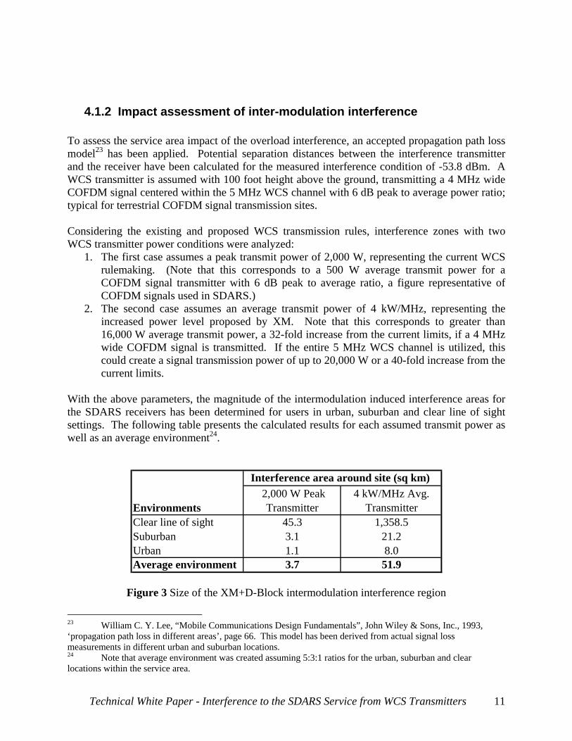
4.1.2 Impact assessment of inter-modulation interference To assess the service area impact of the overload interference, an accepted propagation path loss model23 has been applied. Potential separation distances between the interference transmitter and the receiver have been calculated for the measured interference condition of -53.8 dBm. A WCS transmitter is assumed with 100 foot height above the ground, transmitting a 4 MHz wide COFDM signal centered within the 5 MHz WCS channel with 6 dB peak to average power ratio; typical for terrestrial COFDM signal transmission sites. Considering the existing and proposed WCS transmission rules, interference zones with two WCS transmitter power conditions were analyzed:
1. The first case assumes a peak transmit power of 2,000 W, representing the current WCS rulemaking. (Note that this corresponds to a 500 W average transmit power for a COFDM signal transmitter with 6 dB peak to average ratio, a figure representative of COFDM signals used in SDARS.)
2. The second case assumes an average transmit power of 4 kW/MHz, representing the increased power level proposed by XM. Note that this corresponds to greater than 16,000 W average transmit power, a 32-fold increase from the current limits, if a 4 MHz wide COFDM signal is transmitted. If the entire 5 MHz WCS channel is utilized, this could create a signal transmission power of up to 20,000 W or a 40-fold increase from the current limits.
With the above parameters, the magnitude of the intermodulation induced interference areas for the SDARS receivers has been determined for users in urban, suburban and clear line of sight settings. The following table presents the calculated results for each assumed transmit power as well as an average environment24.
Interference area around site (sq km)
Environments 2,000 W Peak
Transmitter4 kW/MHz Avg.
Transmitter Clear line of sight 45.3 1,358.5Suburban 3.1 21.2Urban 1.1 8.0Average environment 3.7 51.9
Figure 3 Size of the XM+D-Block intermodulation interference region
23 William C. Y. Lee, “Mobile Communications Design Fundamentals”, John Wiley & Sons, Inc., 1993, ‘propagation path loss in different areas’, page 66. This model has been derived from actual signal loss measurements in different urban and suburban locations. 24 Note that average environment was created assuming 5:3:1 ratios for the urban, suburban and clear locations within the service area.
Technical White Paper - Interference to the SDARS Service from WCS Transmitters 11
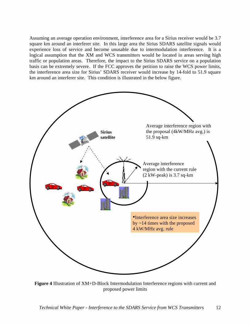
Assuming an average operation environment, interference area for a Sirius receiver would be 3.7 square km around an interferer site. In this large area the Sirius SDARS satellite signals would experience loss of service and become unusable due to intermodulation interference. It is a logical assumption that the XM and WCS transmitters would be located in areas serving high traffic or population areas. Therefore, the impact to the Sirius SDARS service on a population basis can be extremely severe. If the FCC approves the petition to raise the WCS power limits, the interference area size for Sirius’ SDARS receiver would increase by 14-fold to 51.9 square km around an interferer site. This condition is illustrated in the below figure.
Figure 4 Illustration of XM+D-Block Intermodulation Interference regions with current and proposed power limits
Average interference region with the proposal (4kW/MHz avg.) is 51.9 sq-km
Sirius satellite
Average interference region with the current rule (2 kW-peak) is 3.7 sq-km
•Interference area size increases by ~14 times with the proposed 4 kW/MHz avg. rule
Technical White Paper - Interference to the SDARS Service from WCS Transmitters 12
These results show that the intermodulation induced interference will cause significant interference areas for the Sirius SDARS service, especially if the WCS network is deployed in a fashion similar to XM’s terrestrial network with co-located XM and WCS transmitters.
4.2 Single-carrier induced signal overload interference The signal overload interference mechanism occurs in the tuner, is purely linear and results in the desensitization of the receiver circuitry. Interference occurs when an undesired signal (or signals) from an adjacent frequency band is sufficiently strong to cause the Automatic Gain Control (AGC) system of the desired signal’s receiver to respond to the undesired signal rather than the desired signal. The AGC system’s task is to control the amount of the aggregate signal power in the analog tuner circuitry before it is carried to the base-band circuitry for signal demodulation. As the interference level increases, the AGC attenuates the aggregate signal, so as to not exceed the dynamic range of the receiver. Note that in the presence of a strong terrestrial interferer, the entire received signal is attenuated by the AGC and therefore the much weaker desired SDARS satellite signals is also attenuated. Eventually, the desired SDARS satellite signals would be pushed below the threshold of recoverability, resulting in a loss of service. State of the art filter technologies have practical limits, as will be discussed in later sections, and offer very little relief for this type of interference.
4.2.1 Measurements of overload interference In this section, the impact of single carrier overload interference has been quantified individually for the Sirius’ TDM1 and TDM2 satellite signal bands. Measurements were made utilizing the latest state-of-the-art receivers currently in production, providing the highest dynamic range available, thus minimizing the impact of signal overload. The impact of each WCS band and XM’s terrestrial signal acting as a single interferer into the Sirius satellite bands has been tested. Test setup can be found in Section 9.2. In the following table, measured overload levels of individual interference bands are shown. They represent the WCS C-Block, XM Terrestrial and WCS D-Block.
Onset of Muting
WCS C-Block (dBm)
XM Terrestrial
(dBm)
WCS D-Block (dBm)
Sirius TDM1 Satellite Band -57.0 -29.7 -24.5 Sirius TDM2 Satellite Band -42.9 -36.9 -24.8
Figure 5 Measured overload interference levels
Technical White Paper - Interference to the SDARS Service from WCS Transmitters 13
Test results indicate that the WCS C-Block signal creates the most significant overload conditions for the Sirius TDM1 satellite signal. This is not a surprising result since the WCS C-Block is directly adjacent to the TDM1 band with no guard band that may facilitate filtering. A received signal level of only -57 dBm of the WCS C-Block signal will cause a loss of service for the TDM1 signal. As this interference mechanism relates to the physics of large terrestrial signals directly adjacent to weaker satellite signals, this condition is not unique to Sirius. Where the Sirius signal is most affected by a strong adjacent WCS C-Block interferer, XM’s satellite reception is most affected by the WCS D-Block that is directly adjacent to XM’s SDARS spectrum allocation. Comparable XM products have been tested and shown to perform similarly.25 The results for a single interferer into TDM2 are similar to those for TDM1, but for a significantly improved result for a WCS C-Block interferer. In the case of TDM2, receiver desensitization due to signal overload is a less likely contributing mechanism to degradation.
4.2.2 Impact assessment of overload interference To assess the service area impact of the overload interference, the model described in Section 4.1.2 has been utilized, for an overload interference level of -57 dBm. The interference impact has been calculated for both the existing 2,000 W peak limit as well as the increased power limit (average of 4 KW/MHz) advocated by XM. The following table presents the calculated overload interference zones for the Sirius receivers.26
Interference area around site (sq km)
Environments 2000 W Peak Transmitter
4 kW/MHz Avg. Transmitter
Clear line of sight 81.7 2,826.0Suburban 5.3 28.3Urban 1.5 11.3Average environment 6.1 91.2
Figure 6 Size of the WCS C-Block overload interference regions
25 Using the testbed setup described in Section 9.2, overload interference tolerance of an XM receiver was tested. During the test, an XM’s SkyFi2 receiver (made by Delphi) was fed with half of a single satellite power (single satellite power is -100 dBm) in the S1B ensemble while being interfered from the WCS D-Block interferer. Result showed that the XM muted from the D-Block WCS interferer at approximately the same interference level as a Sirius Starmate Replay receiver muted from the C-Block WCS interferer. Thus, the XM receiver was found to be subject to the same impact from the WCS interference sources. 26 Note that average environment was created assuming 5:3:1 ratios for the urban, suburban and clear locations within the service area.
Technical White Paper - Interference to the SDARS Service from WCS Transmitters 14
Assuming an average consumer environment, the service area impacted by overload interference would be 6.1 square km around an interferer site. Within this large area, the Sirius SDARS satellite signals would suffer loss of service and become unusable due to this blanketing interference. Again, assuming XM and WCS transmitters would be located to serve high traffic or population areas, this would create a severe impact to the Sirius SDARS service for the general population. If the FCC approves the petition to raise the WCS power limits, the interference area for Sirius’s SDARS services will increase by 15-fold to 91.2 square kilometers. This condition is illustrated in the figure below.
Sirius satellite
Average interference region with the current rule (2 kW-peak) is 6.1 sq-km
•Interference area size increases by ~15 times with the proposed 4 kW/MHz avg. rule
Average interference region with the proposal (4 kW/MHz avg.) is 91.2 sq-km
Figure 7 Illustration of WCS C-Block overload interference regions
Technical White Paper - Interference to the SDARS Service from WCS Transmitters 15
Signal overload from XM SDARS terrestrial transmitters is currently the most significant cause of service outages for Sirius’ satellite delivery. In many instances, XM has deployed repeaters at locations very low to the ground or with substantial down-tilt of transmit antennas to cause excessive signal levels measured on the street. While cooperative efforts between XM and Sirius have reduced the number of sites causing excessive signal levels, many remain and XM has indicated an inability or unwillingness to alter those sites. Assuming the WCS network is deployed in a fashion similar to XM’s terrestrial network, signal overload will cause substantial interference into the Sirius satellite delivery system. Should the WCS network be deployed in a fashion similar to a cellular/PCS network, the number of sites could multiply several fold, further exacerbating the blanketing interference into the SDARS satellite service
4.3 Investigation of out-of-band emissions interference The third interference mechanism is out-of-band emissions generated by the strong WCS terrestrial signals spilling over into the frequency spectrum of the weak SDARS satellite signals. If the out-of-band emissions are sufficiently high, the noise floor of the SDARS signal band will excessively increase. After a certain level, the Signal to Noise Ratio (SNR) of the SDARS signal will not be sufficient to support proper demodulation of the received SDARS signals. This would occur in conditions where the SDARS signal would otherwise have been successfully received and demodulated in the absence of the interferer. A digital receiver relies on a relatively high signal level to demodulate the desired content in the presence of nominal thermal noise. When out-of-band emissions from an undesired signal fall into the receiver’s in-band frequency spectrum, these emissions add to the noise floor. Thus, the ratio between the levels of the desired signal and the noise floor decreases. As this ratio decreases, the desired signal becomes less detectable by the receiver. The receiver’s Forward Error Correction (FEC) operation can offer limited help to mitigate the increased noise floor effects to continue proper demodulation of the desired signal. Once the desired signal to noise ratio falls below a certain limit, the receiver can no longer detect the desired signals in the presence of excessive noise, and loss of service occurs.
4.3.1 Current WCS Rules Governing Out-of-Band Emissions The FCC's service rules for 2.3 GHz WCS27 require that out-of-band emissions be attenuated below the output power (p, measured in watts) of each transmitter within the licensed band(s) of operation, measured in watts, as follows:
27 47 C.F.R. § 27.53. Certain portable devices are subject to slightly less stringent limits. Id., § 27.53(a)(9).
Technical White Paper - Interference to the SDARS Service from WCS Transmitters 16
1. For fixed operations, including radiolocation: By a factor not less than 80 + 10 log (p) dB on all frequencies between 2320 and 2345 MHz;
2. For mobile operations, including radiolocation: By a factor not less than 110 + 10 log (p) dB on all frequencies between 2320 and 2345 MHz;
3. For fixed and mobile operations, including radiolocation: By a factor not less than 70 + 10 log (p) dB on all frequencies below 2300 MHz and on all frequencies above 2370 MHz; not less than 43 + 10 log (p) dB on all frequencies between 2300 and 2320 MHz and on all frequencies between 2345 and 2370 MHz that are outside the licensed bands of operation.
Despite acknowledging that these stringent limits could have “significant cost or service implications for WCS,”28 the Commission correctly concluded that the need to protect sensitive SDARS receivers in the 2320-2345 MHz band was the more important objective.29
4.3.2 Relationship of Current Rules to Receiver Blanketing Interference The current rules specify out-of-band emissions limits for different classes of WCS transmitters but do not set limits on ground level signals. Thus, the rules only imperfectly address the important inter-modulation and overload issues for the protection of SDARS satellite signals adjacent to the strong terrestrial WCS bands. Blanketing interference dominates the impairment mechanism for a receiver incorporating best practice filtering and overload mitigation technology. The out-of-band emissions limits for WCS are completely ineffective in preventing SDARS service disruption. For example, using the FCC’s WCS out-of-band emission rule for interference to SDARS, one can calculate that a WCS transmitter with 500 W transmit power should reduce its emissions by 101 dB/MHz by the SDARS band30. From the previous section, it was shown that intermodulation or overload interference impacts satellite service around -54 dBm input power to Sirius or XM SDARS receivers. An interferer having -54 dBm in-band signal power at the SDARS receiver will have an out-of-band emission level at -155 dBm, that would be well below the common Sirius SDARS receiver’s noise floor for its satellite signals of about -111 dBm. It can be clearly seen from the typical blanket interference levels that an SDARS receiver will be impaired due to blanketing interference well before it is impaired due to the WCS source out-of-band emissions causing a significant rise in the satellite noise floor.
28 Amendment of the Commission’s Rules to Establish Part 27, the Wireless Communications Service (“WCS”), Report and Order, 12 FCC Rcd 10785, 10855 (1997) (¶ 138). 29 Id. at 10850-10851 (¶¶ 127-129). 30 For 2000 W peak power transmission limit per the existing FCC rules for the WCS band, a COFDM site transmit power can be up to 500 W with 6 dB peak to average ratio. The signal power can be spread over a 4 MHz band located at the center of the 5 MHz WCS band. Signal power within a MHz bandwidth would be 125 W. In this case, the required out-of-band emission would be 80 + 10 log (125W) = 101 dB. Thus, the required WCS signal attenuation at the start of the SDARS band would be 101 dB/MHz.
Technical White Paper - Interference to the SDARS Service from WCS Transmitters 17
While the current rulemaking intended to provide protection to SDARS, without a limit on street level received power, this protection is fruitless. When coupled with a limit on street level received power, the limit on out-of-band interference can be revisited and potentially relaxed. Rule making that comprehensively addresses all potential interference mechanisms will lead to more cost-effective receiver implementations for both WCS and SDARS products.
5 Examples of interference impacts to Sirius service in major markets
Two markets are shown as examples to demonstrate the impact of interference to SDARS receivers. We note that in the Washington, DC and Philadelphia markets, XM has not applied to acquire all WCS spectrum blocks that are considered in these interference analyses. However, Sirius believes that the effects shown here are illustrative of the potential impact in any market.
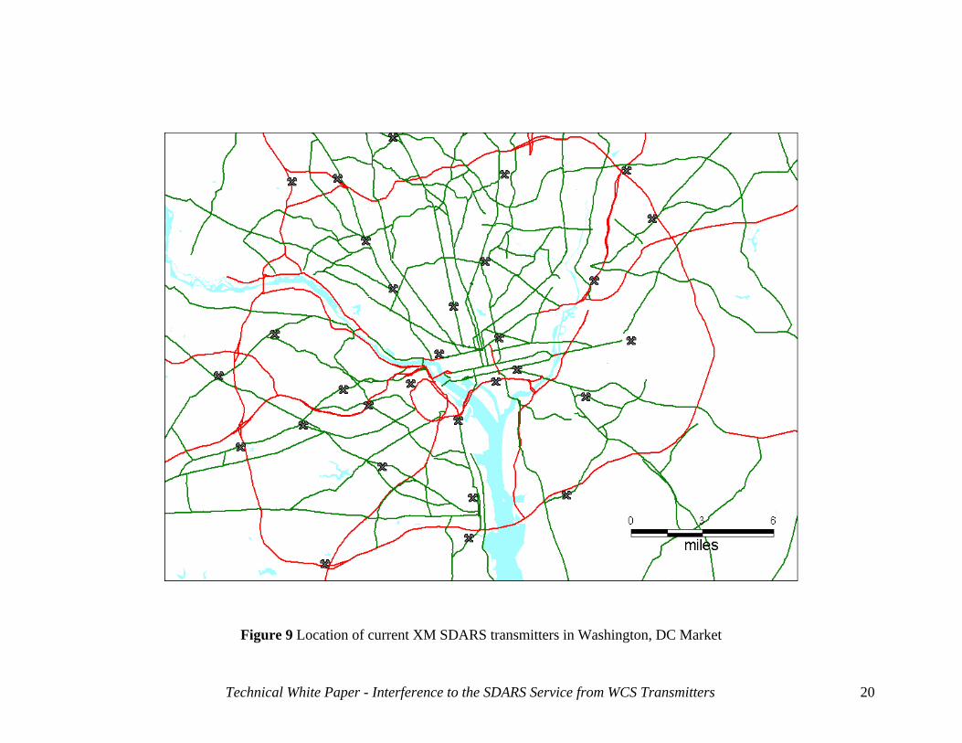
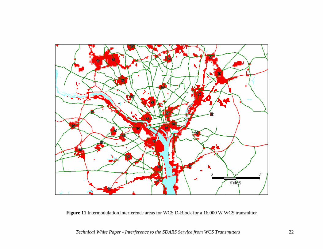
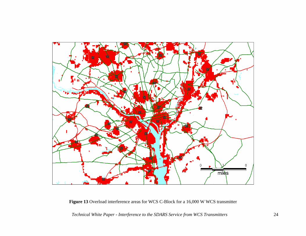
5.1 Washington, DC Market The analysis in the following table indicates the effects on population coverage and traffic volume of the interference generated to Sirius. The predicted interference is generated by intermodulation (Figures 10 and 11) that will occur if XM collocates powerful WCS transmitters at their existing SDARS repeater sites in the Washington, DC market, or by signal overload from individual XM terrestrial transmitters (Figures 12 and 13). For these calculations, it is assumed that XM transmits within the WCS band, a power level that would be permitted under their recent proposal filing31 and assumes the utilization of a 4 MHz wide COFDM signal centered in the 5 MHz WCS block as described in Section 4.1.2.
31 Joint Reply Comments of WCS Wireless LLC and XM Satellite Radio Holdings, Inc., WT Docket No. 03-264 (filed Jan. 17, 2006).
Technical White Paper - Interference to the SDARS Service from WCS Transmitters 18
Technical White Paper - Interference to the SDARS Service from WCS Transmitters 19
Interference Mechanism
Total Area of Interference
(sq. km)
Population Affected
Average Daily Traffic Volume
Receiver Overload from XM terrestrial repeaters 0.7 1,358 19,478
Intermodulation from WCS D-Block & XM 415 485,447 26,087
Signal Overload from WCS C-Block 627 729,754 23,529
Figure 8 Washington, DC Market Interference Impact Assessment
Using CRC-Predict Model with Clutter In the above table,
• Population Affected is the number of people that reside within the interference area. • Mean Average Daily Traffic volume is the total count of motor vehicles passing a point
or segment of a US Interstate/Highway/Major Road/Residential street, in both directions, during a 24-hour period averaged over an entire region. This data basically indicates the number of vehicles that pass a particular point daily within the area of interest.
ADT is a general average for number of vehicles passing a point on a street or highway, thus it could underestimate the count of vehicles with Sirius receivers within the interference zone. By considering the number of streets and highway sections within the interference zone, one can estimate the number of Sirius vehicular users affected by interference. Note that the mean ADT in Figure 8 is at a maximum for the WCS D-Block Case. This is because, as the effecting interference level decreases, the interference zone expands from heavy traffic urban areas to light traffic residential/rural areas, therefore creates gradually decreasing mean traffic count overall as the interference zone expands. The following plots depict the interference areas (shown in red) associated with the signal levels indicated. These were generated using the CRC-Predict propagation model using terrain and clutter data sets. These figures demonstrate that the individual or cumulative effect of the interference into Sirius band would severely affect the Sirius service for the Washington, DC area. As described in Section 4.1.2, two different WCS signal transmission conditions are considered in plotting the following figures:
• Figures 10 and 12 assume a peak transmit power of 2,000 W (or 500 W average COFDM signal with 6 dB peak to average power ratio), representing the current WCS rulemaking.
• Figures 11 and 13 assume an average transmit power of 4 kW/MHz, representing the increased power level proposed by XM (16,000 W average power for a 4 MHz COFDM signal)
Figure 9 Location of current XM SDARS transmitters in Washington, DC Market
Technical White Paper - Interference to the SDARS Service from WCS Transmitters 20
Figure 10 Intermodulation interference areas for WCS D-Block for a 500 W WCS transmitter
Technical White Paper - Interference to the SDARS Service from WCS Transmitters 21
Figure 11 Intermodulation interference areas for WCS D-Block for a 16,000 W WCS transmitter
Technical White Paper - Interference to the SDARS Service from WCS Transmitters 22
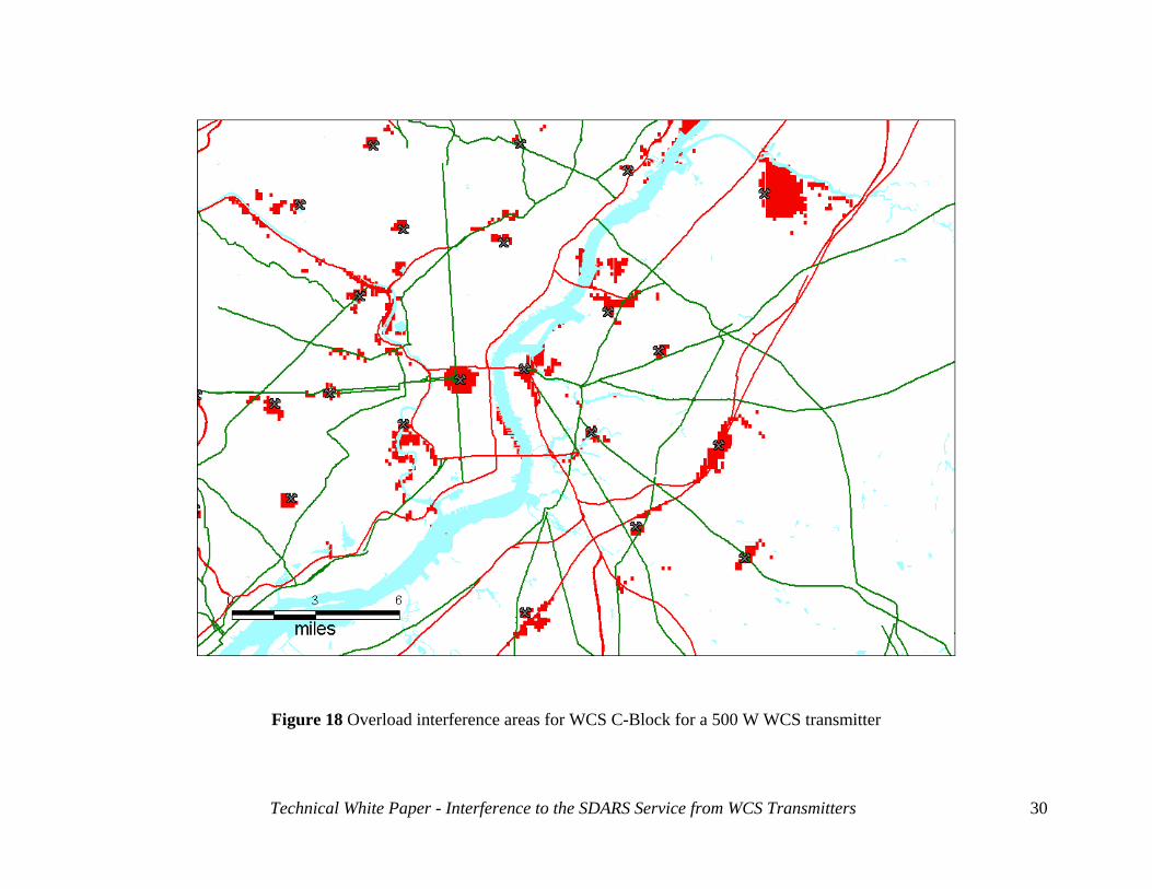
Figure 12 Overload interference areas for WCS C-Block for a 500 W WCS transmitter
Technical White Paper - Interference to the SDARS Service from WCS Transmitters
23
Technical White Paper - Interference to the SDARS Service from WCS Transmitters
24
Figure 13 Overload interference areas for WCS C-Block for a 16,000 W WCS transmitter
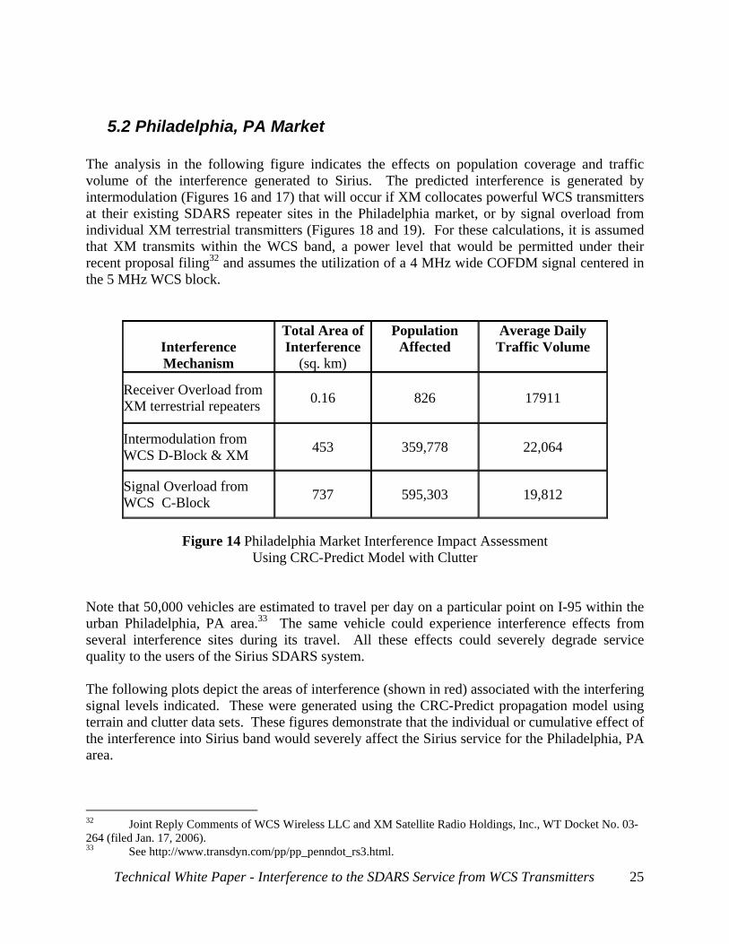
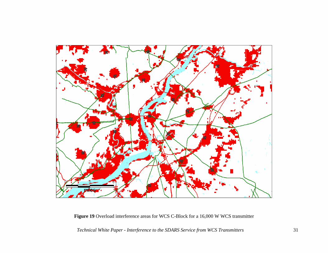
5.2 Philadelphia, PA Market The analysis in the following figure indicates the effects on population coverage and traffic volume of the interference generated to Sirius. The predicted interference is generated by intermodulation (Figures 16 and 17) that will occur if XM collocates powerful WCS transmitters at their existing SDARS repeater sites in the Philadelphia market, or by signal overload from individual XM terrestrial transmitters (Figures 18 and 19). For these calculations, it is assumed that XM transmits within the WCS band, a power level that would be permitted under their recent proposal filing32 and assumes the utilization of a 4 MHz wide COFDM signal centered in the 5 MHz WCS block.
Interference Mechanism
Total Area of Interference
(sq. km)
Population Affected
Average Daily Traffic Volume
Receiver Overload from XM terrestrial repeaters 0.16
826
17911
Intermodulation from WCS D-Block & XM 453 359,778 22,064
Signal Overload from WCS C-Block 737 595,303 19,812
Figure 14 Philadelphia Market Interference Impact Assessment
Using CRC-Predict Model with Clutter Note that 50,000 vehicles are estimated to travel per day on a particular point on I-95 within the urban Philadelphia, PA area.33 The same vehicle could experience interference effects from several interference sites during its travel. All these effects could severely degrade service quality to the users of the Sirius SDARS system. The following plots depict the areas of interference (shown in red) associated with the interfering signal levels indicated. These were generated using the CRC-Predict propagation model using terrain and clutter data sets. These figures demonstrate that the individual or cumulative effect of the interference into Sirius band would severely affect the Sirius service for the Philadelphia, PA area.
32 Joint Reply Comments of WCS Wireless LLC and XM Satellite Radio Holdings, Inc., WT Docket No. 03-264 (filed Jan. 17, 2006). 33 See http://www.transdyn.com/pp/pp_penndot_rs3.html.
Technical White Paper - Interference to the SDARS Service from WCS Transmitters
25
Technical White Paper - Interference to the SDARS Service from WCS Transmitters
26
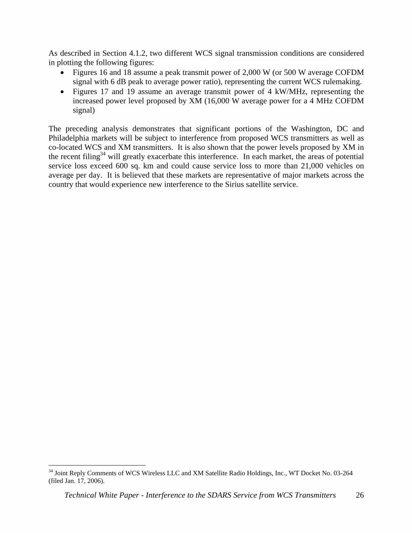
As described in Section 4.1.2, two different WCS signal transmission conditions are considered in plotting the following figures:
• Figures 16 and 18 assume a peak transmit power of 2,000 W (or 500 W average COFDM signal with 6 dB peak to average power ratio), representing the current WCS rulemaking.
• Figures 17 and 19 assume an average transmit power of 4 kW/MHz, representing the increased power level proposed by XM (16,000 W average power for a 4 MHz COFDM signal)
The preceding analysis demonstrates that significant portions of the Washington, DC and Philadelphia markets will be subject to interference from proposed WCS transmitters as well as co-located WCS and XM transmitters. It is also shown that the power levels proposed by XM in the recent filing34 will greatly exacerbate this interference. In each market, the areas of potential service loss exceed 600 sq. km and could cause service loss to more than 21,000 vehicles on average per day. It is believed that these markets are representative of major markets across the country that would experience new interference to the Sirius satellite service.
34 Joint Reply Comments of WCS Wireless LLC and XM Satellite Radio Holdings, Inc., WT Docket No. 03-264 (filed Jan. 17, 2006).
Figure 15 Location of current XM COFDM transmitters in Philadelphia Market
Technical White Paper - Interference to the SDARS Service from WCS Transmitters
27
Figure 16 Intermodulation interference areas for WCS D-Block for a 500 W WCS transmitter
Technical White Paper - Interference to the SDARS Service from WCS Transmitters
28
Figure 17 Intermodulation interference areas for WCS D-Block for a 16,000 W WCS transmitter
Technical White Paper - Interference to the SDARS Service from WCS Transmitters
29
Figure 18 Overload interference areas for WCS C-Block for a 500 W WCS transmitter
Technical White Paper - Interference to the SDARS Service from WCS Transmitters
30
Technical White Paper - Interference to the SDARS Service from WCS Transmitters
31
Figure 19 Overload interference areas for WCS C-Block for a 16,000 W WCS transmitter
6 Newer RF Filter Technology Will Not Eliminate the Interference
The existing Sirius antenna modules contain relatively broadband filters to sufficiently reject unwanted out-of-band signals such as cellular PCS and ISM band signals. The adjacent nature of the WCS frequency bands makes it impractical to reduce WCS interference to a reasonable level with the existing commercially available ceramic or dielectric filters. Sirius has invested in state-of-the-art-filtering technologies including co-funding with XM the development of filters intended for use by WCS receivers. These filters attenuate terrestrial signals from either Sirius or XM terrestrial repeaters to mitigate concerns of receiver-induced inter-modulation for the WCS receivers. This is far easier to address since the satellite signals at the low end of Sirius spectrum and at the high end of the XM spectrum provide an adequate transition band for the filter, and since there is little need to attenuate the relatively weak satellite signals that are adjacent to the WCS transmitted signals. No such transition band exists for protecting the SDARS satellite signals from WCS terrestrial transmissions, dramatically increasing the complexity of any hypothetical brick-wall filter design. The current state-of-the-art filter technology is examined in the following sections. Only two state-of-the-art filter technologies show any promise: Surface Acoustic Wave (SAW) and Bulk Acoustic Wave (BAW). The performance of these filters was analyzed and the results of that analysis are reported herein. Despite Sirius’ substantial investments in SAW and BAW technologies, we have been unable to identify a filter that provides sufficient protection from the interference mechanisms detailed in this white paper.
6.1 SAW filter performance analysis SAW filters technology is characterized by its reliance on electrical/acoustic transducers to develop band-pass filter shapes that are difficult to achieve with more traditional filter technology. While SAW filters are currently employed in Sirius receivers, they are used to separate signal components at Intermediate Frequencies (IF) within the tuner, after the damage from intermodulation or overload interference has been generated in the receiver “front end”. The piezoelectric substrate selected in the SAW filter design is a primary factor in defining the achievable filter performance. Lithium Niobate (LiNbO3) and Lithium Tantalite (LiTaO3) substrate materials could provide a reasonable performance for a band-pass filter (i.e. low insertion loss and minimal pass band amplitude ripple). Unfortunately, these materials have a very high temperature coefficient (-87ppm/°C and -18ppm/°C, respectively). Quartz (SiO2) has the lowest temperature coefficient of piezoelectric materials; hence it is the most promising substrate material for this filter application. However, very low coupling constant (0.06%) of the quartz substrate leads to very high insertion loss (in the range of 7dB to 10dB) for wideband band-pass filter design (14 MHz pass band, including temperature drift and
Technical White Paper - Interference to the SDARS Service from WCS Transmitters
32
manufacturing tolerances). Potentially, quartz SAW filters can help reduce impact of XM COFDM, WCS D-Block interferers for the Sirius SDARS signals, as well as their 3rd order intermodulation products. Typically, in high volume design of Quartz SAW band-pass filters, the pass band is increased to accommodate temperature drift and manufacturing tolerances. A band-pass filter for applications such as this typically needs a 2 to 4 MHz increase in the designed pass band to accommodate these variations. As shown below, the lack of guard band between the SDARS and the WCS spectrum provides no room for filter tolerances to effectively eliminate enough adjacent spectrum energy. The following table shows the best practically achievable and mass producible state-of-the-art SAW filter’s temperature drift behavior; where the SAW filters could only offer a pass band that is much larger than Sirius SDARS band, therefore not providing the required interference mitigation of the adjacent band interference signals. Note that the total filter pass band can move anywhere within the 18.7 MHz range around the Sirius SDARS band, even if it was designed to pass only the Sirius signals within its 12.5 MHz SDARS band. As a result, nearby WCS C-Block and XM terrestrial signal frequencies would fall into the filter pass band as a function of temperature. This behavior, given the operational temperature requirements, prevents the SAW filters from being usable in SDARS applications. Thus, the total temperature range over which the filter must operate in spec is a major concern. A -40°C to +105°C temperature range (standard practice for SDARS automotive components) results in a 1 MHz frequency shift at the cold temperature limit and a 1.2 MHz frequency shift at the hot temperature limit.
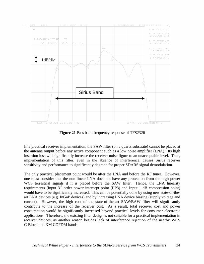
with temperature drift considerations Current SAW designs do not offer a suitable solution to help reduce interference into the Sirius SDARS signals from the XM COFDM and WCS terrestrial signals. To evaluate SAW filter performance, Vectron International developed a prototype SAW Band-Pass Filter (TFS2326) on a quartz substrate. This latest filter has a very high pass band insertion loss (~7.5 dB) and a very high pass band amplitude ripple (on the order of 3dB Peak-to-Peak). Its pass band is also narrower than the Sirius receiver design requirements. The figure below denotes the frequency response of the discussed SAW filter.
Technical White Paper - Interference to the SDARS Service from WCS Transmitters
33
Sirius Band
1dB/div
Figure 21 Pass band frequency response of TFS2326 In a practical receiver implementation, the SAW filter (on a quartz substrate) cannot be placed at the antenna output before any active component such as a low noise amplifier (LNA). Its high insertion loss will significantly increase the receiver noise figure to an unacceptable level. Thus, implementation of this filter, even in the absence of interference, causes Sirius receiver sensitivity and performance to significantly degrade for proper SDARS signal demodulation. The only practical placement point would be after the LNA and before the RF tuner. However, one must consider that the non-linear LNA does not have any protection from the high power WCS terrestrial signals if it is placed before the SAW filter. Hence, the LNA linearity requirements (Input 3rd order power intercept point (IIP3) and Input 1 dB compression point) would have to be significantly increased. This can be potentially done by using new state-of-the-art LNA devices (e.g. InGaP devices) and by increasing LNA device biasing (supply voltage and current). However, the high cost of the state-of-the-art SAW/BAW filter will significantly contribute to the increase of the receiver cost. As a result, total receiver cost and power consumption would be significantly increased beyond practical levels for consumer electronic applications. Therefore, the existing filter design is not suitable for a practical implementation in receiver devices, as another reason besides lack of interference rejection of the nearby WCS C-Block and XM COFDM bands.
Technical White Paper - Interference to the SDARS Service from WCS Transmitters
34
Even though this filter provides 0dB to 10dB rejection of WCS C-Block interference in ideal lab conditions, one can conclude from the above data that this rejection performance does not yield viable receiver designs if temperature, manufacturing tolerance, insertion loss and ripple issues are considered. Realistic, mass-producible, and commercial-grade version of this filter will ultimately have very little WCS C-Block interference rejection (see SAW Filter Technology notes above). Therefore, the current state-of-the-art SAW filter technology is not a candidate to adequately pass the Sirius TDM1 satellite signals while protecting from the neighboring terrestrial WCS C-Block interference.
6.2 BAW filter performance analysis Innovative Film Bulk Acoustic Wave (BAW) Resonator technology has been developed during last several years. BAW filters are also known as Film Bulk Acoustic Resonators (FBAR) filters or thin film resonator (TFR) filters. BAW filters have found applications for RF band-pass filters that are unachievable with SAW filter technology. A BAW band-pass filter is based on a single-port resonator. Its filter effect is based on the electro-acoustic resonance of a piezoelectric material to which a voltage is applied. The resonant frequency becomes higher as the piezoelectric crystal becomes thinner. Extremely thin layers (about 1 µm) of piezoelectric material are needed to exploit this effect in SDARS receivers operating in the gigahertz range. This corresponds to about only 10,000 atomic layers of crystal. This thin piezoelectric layer is deposited on a substrate in a special precipitation process. The standard piezoelectric material for BAW filters is aluminum nitride (AlN). Silicon, for example, can be used as a mechanical carrier. The voltage is applied to the AlN layer by structured thin-film electrodes made of aluminum. The complete structure is located on alternating layers of high and low acoustic impedance. This acts as an acoustic mirror (Fabry-Perot resonator) that reflects the acoustic energy released at the resonant frequency of the BAW back to the resonator. When an external AC voltage is applied to the structure described, electrical energy is converted into acoustic energy and vice versa. If the wavelength of the acoustic waves in the piezoelectric film equals twice the thickness of the AlN film, there is effective electro-acoustic conversion that the BAW is in resonance and oscillates with the frequency applied from outside. In this case, BAW works as band-pass filter tuned for the resonance frequency. The main strengths of BAW technology are:
• High quality factor of resonators, • Steep filter skirts, and • Low insertion attenuation.
BAW filters, like SAW filters have significant temperature sensitivity. For example, the filter shifts down in frequency as the ambient temperature rises. Agilent’s BAW temperature coefficient is typically -30 ppm/°C for ALN thin film substrate, much worse than the SAW filters previously discussed. Thus, similar to the concerns indicated in the SAW discussion in Section 6.1, the total temperature range over which the BAW filter must operate in spec is a
Technical White Paper - Interference to the SDARS Service from WCS Transmitters
35
major concern. A -40°C to +105°C temperature range (standard practice for SDARS automotive components) results in a 5 MHz frequency shift at the cold temperature limit and a 7 MHz frequency shift at the hot temperature limit. The rejection nulls are only 5 MHz off the pass band. The following figure shows the achievable and mass producible state-of-the-art BAW filter’s temperature drift behavior, where the total filter pass band can move anywhere within the 28.5 MHz range around the Sirius SDARS band, even if it was designed to pass only the Sirius signals within its 12.5 MHz SDARS band. Nearby WCS C-Block and XM terrestrial signal frequencies would fall into the filter pass band as a function of temperature. This kind of behavior, given the operational temperature requirements, prevents the BAW filters from being usable in SDARS applications.
with temperature drift considerations There is no known BAW filter design that will provide the requisite protection to the Sirius bands from WCS C-Block and XM terrestrial COFDM bands. BAW band-pass filter may potentially help reduce the WCS D-Block interference to the Sirius SDARS satellite signals. The current BAW designs do not offer a suitable solution.
6.3 Filter technology Summary Sirius and XM have co-funded development of filters for use by WCS receivers in order to attenuate any terrestrial signals from either Sirius or XM terrestrial transmissions. The goal is to mitigate concerns of receiver-induced inter-modulation for the WCS receivers. Considering the frequency separation of the SDARS terrestrial repeaters from the WCS band, this is a far easier case to address with state-of-the-art filter technology. The satellite signals at the low end of Sirius’s spectrum and at the high end of the XM’s spectrum provide an adequate transition band for this filter, and there is little need to attenuate the relatively weak satellite signals that are adjacent to the WCS transmitted signals. However, there is no such transition band for protecting the SDARS satellite signals from WCS terrestrial transmissions since the SDARS satellite signal spectrum is adjacent to the interfering terrestrial WCS bands. An ideal brick-wall filter would need to be implemented to mitigate such interference. Despite Sirius’ considerable investments in new SAW and BAW filter technology, we have not been able to identify a filter that meets our requirements for interference rejection as explained above.
Technical White Paper - Interference to the SDARS Service from WCS Transmitters
36
7 Discussion of SDARS interoperability operation The ability to offer interoperable SDARS receivers will also be affected by the transfer of WCS licenses to XM. Interoperable receiver will allow consumers to purchase one device that can receive either or both of the licensed SDARS services. Sirius and XM have invested significant effort and resources in the development of interoperable technologies to fulfill the directive of the FCC. In addition to receiver development work co-funded by Sirius and XM, the two companies have published interoperable specifications for various SDARS subsystems, including an interoperable antenna – which is currently in production. Advanced development efforts have focused on an interoperable tuner that can facilitate both services and interface to both a Sirius and XM digital decoder. To make these interoperable technologies affordable and practical, commonality in circuits is being exploited. As such, interoperable antennas and tuners are more wideband than their non-interoperable versions and therefore are more prone to be negatively impacted by the interference mechanisms described in this paper. Using a parochial view, an SDARS interoperable radio will not receive the Sirius service as well as a Sirius non-interoperable version. As an example, the Sirius receiver utilizes additional filtering to lessen the impact of signal overload from the XM terrestrial repeater network. This filter is included in the design of our antennas and attenuates the frequencies around the XM terrestrial signal. Such filtering is not possible in an interoperable antenna and therefore the interoperable receiver will be more sensitive to signal overload from the XM repeater signal. Additionally, since there is no attenuation to the XM terrestrial repeater signal, the interoperable receiver will also be more sensitive to receiver-induced inter-modulation caused by combinations of XM and WCS transmissions. Furthermore, an interoperable receiver will be far more sensitive to signal overload from the WCS C and D-Block transmissions as the entire SDARS band must be accommodated, leaving no ability to provide adequate filtering of the WCS signals. Similar sensitivities will result from the use of a common, interoperable tuner that has wider bandwidth and likewise must pass the entire SDARS spectrum.
8 Summary and Conclusions This White Paper has conclusively demonstrated that:
• 2.3 GHz WCS licensees are obligated to protect nearby lower-power SDARS satellite transmissions.
• Collocation of WCS and XM terrestrial transmitters resulting from XM’s proposed acquisition of WCS licensees will generate intermodulation products that interfere with reception of satellite downlink bands licensed to Sirius.
Technical White Paper - Interference to the SDARS Service from WCS Transmitters
37
• Sirius SDARS receivers are also subject to brute-force overload interference from future WCS C and D-Block transmitters and existing XM SDARS terrestrial repeaters.
• Filters will not eliminate the interference, and could preclude further development of interoperable XM and Sirius receivers.
• Existing out-of-band emissions limits offer no protection from ground-level signal overload, and should be replaced by power flux density limitations on both SDARS and WCS terrestrial transmitters.
• If unaddressed, the predicted levels of interference would affect millions of subscribers.
Technical White Paper - Interference to the SDARS Service from WCS Transmitters
38
9 Appendix
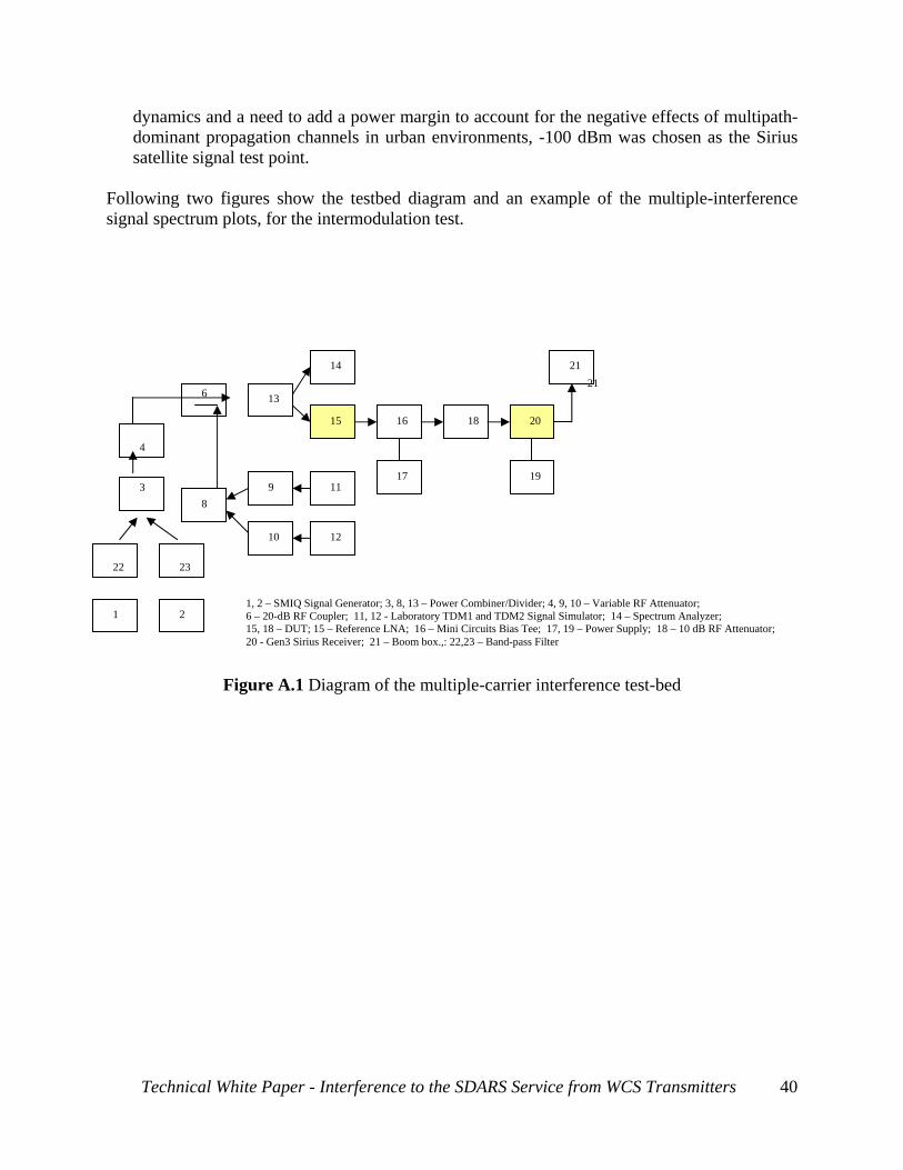
9.1 Multiple Interferer Test Setup Please refer to the following figure for a description of the lab setup for interference testing. Blocks 1 and 2 shown in the figure are Rhode and Swartz SMIQ signal generators that were used to create the interference signals. Band-pass filters 22 and 23 shaped the interfering signals according to the WCS band Transmitter and Satellite Radio Terrestrial Repeater spectral mask requirements, discussed before in this document. In both cases the test signal was a COFDM signal with peak to average ratio of 6 dB. The COFDM signal was placed at the center of the simulated band. The WCS band signal was simulated using 4 MHz COFDM signal generator. The XM terrestrial repeater signal was simulated using a 5 MHz COFDM signal generator. Signal sources 1 and 2 are filtered by filters 22 and 23 and combined through combiner 3, attenuator 4, coupler 6 and splitter 13 to create an existing interference pattern that current Sirius radios would see. Splitter 13 splits the signal to Spectrum analyzer 14 and reference LNA 15. Reference LNA 15 is representative of the input to an of-the-shelve Sirius antenna module. Note here that the LNA test module was created by removing the antenna element from the antenna module, and creating a 50 ohm input to the LNA. The effective noise figure looking into this LNA input is approximately 0.85 db. Signal source units 11 and 12, which provide the Sirius TDM 1 and 2 signals respectively are attenuated through 9 and 10 and combined in 8 to provide signal level that are representative of what a radio receiver would see in the field. The antenna module 15 receives its power through power supply 17 and bias tee 16. The signal, applied through attenuator 18, simulating antenna RF cable loss, is then applied to the device under test (DUT) contained in 20, a Gen.3 radio receiver. It should be noted that this unit represent the current units that are being deployed in the field. Unit 19 is self-explanatory as supplying power to the two units and the boom box 21 provides audio feedback to the tester. The following parameters were used in the above-described test set up. 1) Device Under Test (DUT):
• Three Gen 3.0 SIR-UFM1 Starmate Replay receivers, Model ST-2 (SID6174928411, SID 8829508786, SID100971030077);
• One Gen 3.0 SIR-UFM1 Streamer GTR receiver, Model SIRr-GTRC1 (SID007770818555).
2) Reference LNA (for antenna): Version A, Serial # 010 3) Blocking Criteria: Audio Mute of DUT 4) Test signal: Sirius TDM1 and TDM2 fully encoded laboratory test signals at -100 dBm input
power to the LNA. This is a population-weighted representative of what would be encountered in urban environments in typical reception conditions. Population-averaged Sirius satellite signal level on the west coast, central regions and the east coast are -101.1 dBm, -98.6 dBm and -98.8 dBm. Further averaging these levels with respective region populations provide -99.2 dBm overall signal level on the ground at the antenna skin paint. Assuming 3.5 dB average peak-to-peak satellite signal variation from the Sirius constellation
Technical White Paper - Interference to the SDARS Service from WCS Transmitters
39
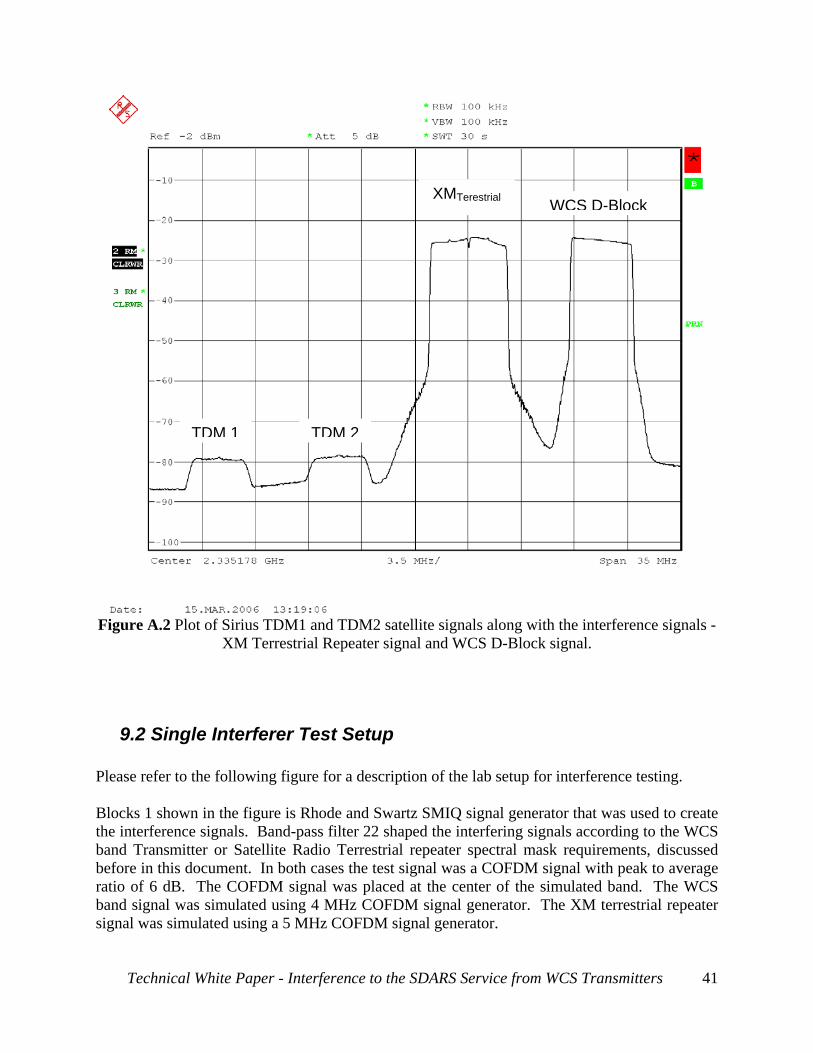
dynamics and a need to add a power margin to account for the negative effects of multipath-dominant propagation channels in urban environments, -100 dBm was chosen as the Sirius satellite signal test point.
Following two figures show the testbed diagram and an example of the multiple-interference signal spectrum plots, for the intermodulation test.
2
Tec
1 4
3
1, 2 – SMIQ Signal Generator; 3, 8, 13 – Power Combiner/Divider; 4, 9, 10 – Variable RF Attenuator; 6 – 20-dB RF Coupler; 11, 12 - Laboratory TDM1 and TDM2 Signal Simulator; 14 – Spectrum Analyzer;
9.2 Sing Please refer to Blocks 1 showthe interferencband Transmibefore in this ratio of 6 dB.band signal wsignal was sim
Technica
TDM
ot of Sirius TDM1XM Terrestri
le Interferer T
the following figu
n in the figure is Re signals. Band-ptter or Satellite Radocument. In both The COFDM sigas simulated usingulated using a 5 M
l White Paper - Int
TDM
and TDM2 satellite signals along wial Repeater signal and WCS D-Block
est Setup
re for a description of the lab setup fo
hode and Swartz SMIQ signal generass filter 22 shaped the interfering sigdio Terrestrial repeater spectral ma cases the test signal was a COFDM nal was placed at the center of the 4 MHz COFDM signal generator. Hz COFDM signal generator.
erference to the SDARS Service from
WCS D-Block
th the interference signals - signal.
r interference testing.
ator that was used to create nals according to the WCS sk requirements, discussed signal with peak to average simulated band. The WCS The XM terrestrial repeater
WCS Transmitters 41
Signal source 1, filter 22, attenuator 4, coupler 6 and splitter 13 are utilized to create an existing interference pattern that current Sirius radios would see. Splitter 13 splits the signal to Spectrum analyzer 14 and reference LNA 15. Reference LNA 15 is representative of the input to a Sirius antenna module with a 0 db gain antenna without the antenna element. The effective noise figure looking into this LNA input is approximately 0.85 db. Signal source units 11 and 12, which provide the Sirius TDM 1 and 2 signals respectively are attenuated through 9 and 10 and combined in 8 to provide signals that are representative of what a radio receiver would see in the field. The antenna module 15 receives its power through power supply 17 and bias tee 16. The signal, applied through attenuator 18, simulating signal loss in antenna feeder cable, is then applied to the device under test (DUT) contained in 20, a Gen.3 Starmate radio receiver. It should be noted that these test unit were acquired from the current receivers that are being deployed in the field. Unit 19 is self-explanatory as supplying power to the two units and the boom box 21 provides audio feedback to the tester. The following parameters were used in the above-described test set up. 1. Device Under Test (DUT):
• Three Gen 3.0 SIR-UFM1 Starmate receivers Model ST-2, SID6174928411 (SID 8829508786, SID100971030077);
• One Gen 3.0 SIR-UFM1 Stareamer receiver (Model SIRr-GTRC1, SID007770818555). 2. Reference LNA (for antenna): Version A, Serial # 010 3. Blocking Criteria: Audio Mute of DUT 4. Test signal: Sirius TDM1 and TDM2 fully encoded laboratory test signals at -100 dBm input level to LNA.
Following two figures show the testbed diagram and an example of the single-interference signal spectrum plots for the overload interference tests.
Technical White Paper - Interference to the SDARS Service from WCS Transmitters