63
Licentiate Thesis in Civil and Architectural Engineering Design of grout curtains under dams founded on rock SUIHAN ZHANG Stockholm, Sweden 2021 kth royal institute of technology

Licentiate Thesis in Civil and Architectural Engineering
Design of grout curtains under dams founded on rockSUIHAN ZHANG
Stockholm, Sweden 2021
kth royal institute of technology

Design of grout curtains under dams founded on rockSUIHAN ZHANG
Licentiate Thesis in Civil and Architectural EngineeringKTH Royal Institute of TechnologyStockholm, Sweden 2021
Academic Dissertation which, with due permission of the KTH Royal Institute of Technology, is submitted for public defence for the Degree of Licentiate of Engineering on Monday the 14th June at 9:00 a.m. in Stora konferensrummet (M108), KTH, Brinellvägen 23, Stockholm

© Suihan Zhang ISBN: 978-91-7873-846-5TRITA-ABE-DLT-2116 Printed by: Universitetsservice US-AB, Sweden 2021

iii
Abstract Grouting has long been implemented as a ground improvement technique to reduce the seepage through the rock mass. Grout curtains are usually constructed under dams as a barrier to prevent leakage from the reservoir. So far, the grout curtains under dams have mainly been designed by using an empirical design approach. However, the empirical approach has its limitations. Generally, the usage of “rules of thumbs” makes the design highly dependent on the experience of the designers. Lack of experience can result in insufficient or over-conservative grout curtains. For example, the stop criteria for the grouting process adopted by the empirical approach can lead to long grouting time and thus becomes inefficient. In addition, high grouting pressure may cause unexpected deformations of the rock and open up new leakage paths.
To deal with these limitations, a theory-based design methodology has been developed. Theories on rock grouting developed in recent decades are used to build up the design methodology. In the theory-based design methodology, the grout curtain is treated as a structural component in the dam foundation. The geometry and location of the grout curtain is first designed with respect to three requirements: (i) the hydraulic conductivity reduction, (ii) prevention of erosion of fracture infillings and (iii) optimization of uplift reduction. Grouting work is then designed to obtain the designed geometry of the grout curtain. In the design of the grouting work, analytical calculations are implemented to determine the grouting pressure, grouting time and grout hole layout. The stop criteria are based on the grouting time, which is believed to obtain better efficiency. The principles of the observational method are implemented to deal with the uncertainties involved in the grouting process.
One of the main limitations with the proposed methodology is the limited research on the erosion process of fracture infilling materials in flowing water. To study this issue, coupled numerical analyses are

iv
performed to better understand the initiation of erosion of fracture infillings. The results show that the Hjulström and Shields diagram are not appropriate to be used to estimate the incipient motion of fracture infilling materials. Instead, a previous equation derived under laminar flows shows better agreement with the results.
Keywords Grout curtains, rock grouting, dams, erosion, infilling materials in rock fractures

v
Sammanfattning Injektering har länge använts som en metod för att förstärka grunden och reducera vattenflödet i en bergmassa. Injekteringsridåer uppförs ofta under dammar som en barriär med syfte att förhindra läckage av magasinets vatten. Hittills har injekteringsridåerna i huvudsak dimensionerats baserat på empiriska metoder. De empiriska metoderna har emellertid sina begränsningar. Användandet av olika tumregler resulterar i att dimensioneringen i hög utsträckning är beroende av ingenjörens erfarenhet. Brist på erfarenhet kan resultera i en ineffektiv, eller en för konservativ, utformning av injekteringsridåerna. Till exempel kan de stoppkriterier som tillämpas i det empiriska tillvägagångssättet leda till en för lång injekteringstid och därmed bli ineffektiv. Utöver detta kan höga injekteringstryck leda till oväntade deformationer i bergmassan och nya läckagevägar.
För att hantera dessa typer av begränsningar har en teoribaserad dimensioneringsmetodik utvecklats. Teorier för berginjektering som utvecklats under de senaste decennierna används för att bygga upp metodiken. I metodiken utformas injekteringsridån som en strukturell komponent i berggrunden under dammen. Den geometriska utformningen och läget för injekteringsridån bestäms med hänsyn till tre kriterier: (i) erforderlig reduktion av den hydrauliska konduktiviteten, (ii) förhindrande av erosion av sprickfyllnadsmaterial, och (iii) optimering av reduktionen i upptryck under dammen. Injekteringsarbetet utformas därefter i syfte att eftersträva den erforderliga utformningen. I utformningen av injekteringsarbetet används analytiska beräkningar för att bestämma injekteringstryck, injekteringstid och hålavstånd. Stoppkriterier baseras på erforderlig injekteringstid, vilket bedöms uppnå en mer effektiv injektering. Principerna för observationsmetoden används för att hantera de osäkerheter som kvarstår.

vi
En av de huvudsakliga begränsningarna med den föreslagna metodiken är den begränsade kunskapen som idag finns om erosion av sprickfyllnadsmaterial vid flödande vatten. För att studera denna fråga genomfördes kopplade numeriska analyser för att bättre förstå processen kring initiering av erosion av sprickfyllnadsmaterial. Resultaten visar att Hjulströms och Shields diagram inte är lämpliga att använda. Istället visar en tidigare framtagen ekvation för laminära förhållanden en bättre överensstämmelse.
Nyckelord Injekteringsridåer, berginjektering, dammar, erosion, sprickfyllnadsmaterial

vii
Preface The research presented in this licentiate thesis was carried out between January 2019 and April 2021 at the Division of Soil and Rock Mechanics, Department of Civil and Architectural Engineering, at KTH Royal Institute of Technology in Stockholm, Sweden.
The work was supervised by Ass. Prof. Fredrik Johansson. His guidance, support and encouragement has been invaluable to my studies. I would like to thank Dr Håkan Stille, Professor Emeritus for his insights in the field of rock grouting and our inspiring discussions. Dr Penghua Teng is acknowledged for his support and help throughout my studies. I also appreciate the help and suggestions from my reference group, which consists of Prof. Nadhir Alansari (Luleå University of Technology, LTU), Ingvar Ekström (Sweco), Anders Isander (Uniper), Prof. Emeritus Sven Knutsson (LTU), Lic. Johan Lagerlund (Vattenfall), Prof. Jan Laue (LTU), Magnus Svensson (Fortum), Adj. Professor Peter Viklander (LTU/Vattenfall) and Dr. Marie Westberg Wilde (KTH/AFRY).
I would like to thank my colleagues at KTH and all my friends in Sweden for their friendship and moral support, especially during the difficult corona time.
Last but certainly not least, I would like to give my appreciation to my parents, Huijie and Xingfeng, and my partner Puqiao. Their beloved support is more than precious. Stockholm, June 2021 Suihan Zhang


ix
Funding acknowledgement The research presented in this thesis was carried out as a part of "Swedish Hydropower Centre - SVC". SVC has been established by the Swedish Energy Agency, Energiforsk and Svenska Kraftnät together with Luleå University of Technology, KTH Royal Institute of Technology, Chalmers University of Technology and Uppsala University.
Participating companies and industry associations are: Andritz Hydro, Boliden, Fortum Generation, Holmen Energi, Jämtkraft, Karlstads Energi, LKAB, Mälarenergi, Norconsult, Rainpower, Skellefteå Kraft, Sollefteåforsens, Statkraft Sverige, Sweco Energuide, Sweco Infrastructure, Tekniska verken i Linköping, Uniper, Vattenfall R&D, Vattenfall Vattenkraft, Voith Hydro, WSP Sverige, Zinkgruvan and AFRY.


xi
List of appended papers This licentiate thesis is based upon the following scientific articles:
Paper A Zhang S, Johansson F. 2021. “On the required thickness of the grout curtain under dams”. In: ICOLD Symposium on Sustainable Development of Dams and River Basins, New Delhi, 24th - 27th February 2021. INCOLD.
Zhang and Johansson developed the design concept. Zhang performed the calculations and wrote the paper. Johansson supervised the research and assisted with comments on the writing.
Paper B Zhang S, Johansson F, Stille H “Design methodology of grout curtains under dams founded on rock.” Submitted to Geotechnical and Geological Engineering.
Zhang, Johansson and Stille together developed the design methodology. Zhang performed the calculations and wrote the paper. Johansson supervised the research and assisted with comments on the writing.
Paper C Teng P, Zhang S, Johansson F. “Numerical modelling of incipient motion of fracture infillings.” Submitted to International Journal of Rock Mechanics and Mining Sciences.
Zhang raised the research questions and provided the background. Zhang and Teng performed the literature review and wrote the introduction of the paper. Teng carried out the numerical analyses using CFD-DEM and wrote the methodology and results sections assisted by Zhang and Johansson. Teng and Zhang wrote the discussion and conclusions assisted by Johansson.

xii
Other publications Zhang has also contributed to the following publications within this research project. However, it is not appended in this thesis: Zhang S, Johansson F. 2021. “Design of grout curtains”. Energiforskrapport 2021-720. Stockholm: Energiforsk.

xiii
Contents 1. Introduction .......................................................................... 1 1.1. Background ........................................................................ 1 1.2. Research project and thesis aims ....................................... 3 1.3. Research methodology ....................................................... 3 1.4. Outline of thesis ................................................................ 4 1.5. Limitations ....................................................................... 4
2. Literature review and theories .............................................. 7 2.1. Empirical grout curtain design for dam foundations ......... 7 2.1.1. General principles ............................................................................... 7 2.1.2. Position and geometry of grout curtain ........................................... 8 2.1.3. Grout curtain and drainage .............................................................10 2.1.4. Grout mix design and grout penetrability ......................................10 2.1.5. Grouting pressure ............................................................................. 11 2.1.6. Stop criteria ...................................................................................... 13 2.1.7. Split-spacing grouting and completion criteria .............................. 13
2.2. State-of-the-art theories on rock grouting ....................... 15 2.2.1. General aspects ................................................................................. 15 2.2.2. Section transmissivity and fracture aperture ................................. 15 2.2.3. Penetrability of grout ....................................................................... 15 2.2.4. Grouting pressure with respect to hydraulic jacking ..................... 16 2.2.5. Stop criteria based on grouting time .............................................. 18 2.2.6. Erosion of grout and fracture infilling materials .......................... 20 2.2.7. The use of the observational method in rock grouting .................. 21
3. Theory-based design methodology ...................................... 23 3.1. Preliminary design .......................................................... 23 3.2. Grouting execution .......................................................... 27 3.3. Dam safety management ................................................. 27
4. Summary of appended papers ............................................. 29 4.1. Paper A: On the required thickness of grout curtains under
dams ....................................................................................... 29

xiv
4.2. Paper B: Design methodology for grout curtains under dams founded on rock ............................................................ 30 4.3. Paper C: Numerical modelling of incipient motion of
fracture infillings .................................................................... 30
5. Discussion ........................................................................... 33 5.1. Empirical knowledge ....................................................... 33 5.2. Advantages with the suggested design methodology ....... 33 5.3. Limitations with the suggested design methodology ....... 35 5.4. Erosion of infilling materials .......................................... 36
6. Conclusions ......................................................................... 39 7. Suggestions for future work ................................................ 41 References .............................................................................. 43
INTRODUCTION | 1
1. Introduction
1.1. Background
Grouting is commonly performed to seal the permeable rock fractures – thus limiting the groundwater seepage through the rock mass in underground constructions such as tunnels and dam foundations. By injecting grout into the rock mass, the hydraulic conductivity of the rock mass is expected to be reduced after the grout hardens (Houlsby 1990; Weaver and Bruce 2007; Gustafson 2012; Stille 2015).
For dams founded on rock, curtain grouting along the basis of the dam is common practice to minimize the water loss from the reservoir (Statens Vattenfallsverk 1968; CDA 2007; FERC 2016; Swedenergy 2020a; Ewert and Hungsberg 2018). The grout curtain, which is the result of the curtain grouting, is functioning as an impervious barrier under the dam. It reduces the seepage through the rock foundation. Due to this reduction, the uplift force from the pore pressure in the dam foundation acting on the base of the dam can also be reduced (Casagrande 1961; Ewert 1985; Houlsby 1990; Ruggeri 2004; Ewert and Hungsberg 2018). Therefore, the grout curtain, together with the drainage, reduces the risk of sliding for dams with a large base, such as concrete gravity dams. Despite the positive effects, the grout curtain also steepens the hydraulic gradient within the curtain, increasing the risk of erosion of infilling materials, if such are present in the fractures. The erosion primarily takes place along any unsealed fractures, including fully filled fractures and partly filled fractures, where flow may still exist. This adverse effect may result in degradation of the grout curtain.
The design of grout curtains under dams has mainly been empirical ever since grouting was first implemented in dam foundation improvement. Classic textbooks from e.g. Houlsby (1990), Weaver and Bruce (2007) and guidelines from e.g. Statens Vattenfallsverk (1968) elaborate on the

2 | INTRODUCTION
empirical design methods for grout curtains under dams. In the empirical design practice, the grouting work is seen as a foundation improving measure. The geometry of the grout curtain, especially the thickness, is determined empirically and there is no specific thickness the grout curtain has to reach. Only the number of rows of the grout holes represents a thick or a thin grout curtain. A thin grout curtain may induce the problem of erosion of any fracture infilling materials, while an overly thick grout curtain may result in inefficient use of time and material. In addition, the stop criteria of grouting are based on the concept of “refusal” (Weaver and Bruce 2007), which means keeping injecting until the grout flow rate reaches a low value and remain lower than that value for a given period. This may result in a long and inefficient grouting process.
In recent decades, extensive research efforts carried out mainly in Sweden have attempted to describe the rock grouting process and grouting factors in a theoretical perspective. The studied grouting aspects include hydrogeology in the rock mass (Zimmerman and Bodvarsson 1996; Hernqvist et al. 2014; Zou et al. 2015), grout properties (Håkansson 1993; Ericsson and Stille 2003; Draganović and Stille 2011), grout spread in relation to grouting time (Gustafson and Stille 2005; Stille et al. 2009; El Tani 2012; Gustafson et al. 2013; El Tani and Stille 2017; Funehag and Thörn 2018; Zou et al. 2018), grouting pressure and hydraulic jacking during grouting (Lombardi and Deere 1993; Brantberger et al 2000; Gothäll and Stille 2009; Rafi and Stille 2015a). The rock grouting theories have been summarized by Stille (2015) and executed in several tunneling projects in Sweden (Stille et al. 2009; Holmberg et al. 2012). Stille et al. (2012) and Rafi and Stille (2014) applied some of the theories in dam projects in Laos and Iran. However, a thorough design methodology for grout curtains based on the theories is yet missing, leaving a gap between the state-of-the-art grouting theories and their application in the design of grout curtains under dams. A theory-based design methodology is expected to deal with the preceding problems from the empirical design. It has the potential to help improve the efficiency of the grouting and deal with the uncertainties by implementing the principles of the observational method.

INTRODUCTION | 3
1.2. Research project and thesis aims
The overall aim of this research project is to develop design methodologies for grout curtains under new and existing dams based on the existing theories on rock grouting and the specific requirements on dam foundation grouting.
This licentiate thesis, which constitute the first part of this research project, aims to:
• Describe the limitations of the current empirical design methodology.
• Develop a theory-based design methodology for grout curtains under new dams and discuss its application.
• Introduce the issue of internal erosion of fracture infilling materials in the grouted zone after the dam has been constructed and discuss threshold conditions for initiation of erosion.
1.3. Research methodology
The research project started with literature studies on both the conventional empirical design methodologies of grout curtains and the state-of-the-art theories on rock grouting. The limitations of the empirical design methodologies were investigated and compared with rock grouting theories. From this comparison, limitations in the existing theories and the gap in knowledge were identified.
To fill parts of this this gap, the development of a theory-based design methodology was initiated. In the development process, the characteristics of existing rock grouting theories were combined with the knowledge on grout curtain design from the author and experienced grouting experts. It resulted in the design methodology proposed in this thesis.
Due to the lack of available dam projects, design examples following the developed methodology was conducted in both Paper A and B. The examples were performed on grout curtains of fictitious concrete dams to show the applicability of the design methodology and present the different stages of grout curtain design.

4 | INTRODUCTION
In paper C, numerical simulation based on a coupled Computational Fluid Dynamics (CFD)-Discrete Element Method (DEM) approach was performed to investigate the incipient motion of fracture infillings. The calculations were performed in a simulated three-dimensional rock fracture with infillings of fine sand. The simulations were performed in an open-source CFD-DEM coupling engine, CFDEM®, which is able to run parallel simulations in DEM (LIGGGHTS) and CFD (OpenFOAM) solvers. The model of the fracture was generated based on data from a natural fracture obtained with high-resolution optical scanning.
Discussions were raised based on the findings of the research and conclusions were drawn according to the thesis aims.
1.4. Outline of thesis
This thesis starts with an introduction chapter introducing the background, the aim and the limitations of the thesis and the research project. Chapter 2 presents the empirical design approach for grout curtains under dams and the state-of-the-art theories related to rock grouting. In Chapter 3, a developed theory-based design methodology for grout curtains under dams is presented together with a general description of all the phases in the methodology. The appended papers are summarized in Chapter 4. Chapter 5 raises discussions over the proposed methodology from various aspects. The thesis ends with a conclusion over the research work and suggestions for future research.
1.5. Limitations
This thesis focuses on the design methodology for grout curtains under new dams. The methodology, however, does not cover all aspects of a grouting project for dams. Practical aspects such as drilling methods, equipment, grouting facilities, contract issues and other related issues is not discussed in the thesis.
This design methodology simplifies the fractures in the rock mass as ideal two-dimensional discs. The design must be subject to careful

INTRODUCTION | 5
evaluation and necessary modification based on the geological conditions on sites. In addition, the design methodology is mainly applicable for new grout curtains. The remedial grouting is only briefly discussed in this thesis with respect to some basic principles.


LITERATURE REVIEW AND THEORIES | 7
2. Literature review and theories
This chapter consist of two sections. Section 2.1 mainly describes the classic empirical design approach for grout curtains under dams. This section focuses on the important aspects of the grout curtain design instead of on the entire design process. Section 2.2, on the other hand, introduces the state-of-the-art theories related to rock grouting, which can be implemented in the design methodology for grout curtains as further discussed in Chapter 3.
2.1. Empirical grout curtain design for dam foundations
2.1.1. General principles
The primary aim for grouting under dams is to reduce the hydraulic conductivity of the rock mass. Therefore, the basic requirement on a complete grout curtain is built on the desired reduction on the hydraulic conductivity. The suggestions from Houlsby (1990) and Swedenergy (2020a) are shown in Figure 2-1. In the figure, the requirements are given in details, corresponding to water value, different types of dams, geometry of dams and specific case scenarios. The unit for hydraulic conductivity of the rock mass in the figure is Lugeon, with 1 Lugeon unit, defined as the loss of water in liters per minute and per meter borehole at an over-pressure of 1 MPa (Lancaster-Jones 1975).
Having the requirements on the grout curtain, thorough site investigations on the site’s geological and hydrogeological features need to be performed before starting the design. The geometry of the grout curtain, the grouting pressure and stop criteria of each grouting run and other aspects of the grout curtain design need to be determined empirically according to the results from the site investigations. Failure to interpret the

8 | LITERATURE REVIEW AND THEORIES
Figure 2-1: Requirements on the grout curtain with respect to the hydraulic conductivity in the rock mass (adapted from Houlsby 1990 and Swedenergy 2020a).
results can lead to insufficient or an over-conservative grout curtain and possibly unexpected behaviors during grouting such as hydraulic jacking. Grouting textbooks such as Houlsby (1990) and Weaver and Bruce (2007) have extensively described the required investigations for grouting under dams and how the grouting should be executed.
2.1.2. Position and geometry of grout curtain
For concrete dams, the grout curtain is usually constructed near the heel of the dam to maximize its effect of reducing seepage and uplift. As for
How valuable is water lost by leakage?
PreciousWorth the cost
of intensivegrouting
Ofnegligible value
1Lugeon
2 or 3Lugeon
No Yes
Does piping of foundation materialneed to be prevented?
3Lugeon
Types of dam
Concrete dams
Embankment damsEarth/rockfillMembrane faced
Single-rowcurtain
Multiple-rowcurtain
5 to 10Lugeon
7 to 15Lugeon
3 to 7Lugeon
5 to 10Lugeon
3 to 5Lugeon
5 to 7Lugeon
Houlsby (1990):
RIDAS (2011):Dam height h
> 30m< 30mDepth 0-6m: 2 Lugeon
6-10m: 3 Lugeon
10-20m: 4 Lugeon
Depth 0-6m: 1 Lugeon
6m-1/3h: 2 Lugeon
1/3h-2/3h: 3 Lugeon

LITERATURE REVIEW AND THEORIES | 9
embankment dams, the grout curtain has the effect of reducing the risk of internal erosion of the core materials. Therefore, grout curtains under embankment dams are usually located beneath the impervious core.
The geometry of a grout curtain contains three dimensions: thickness, depth and length.
In the empirical design of a grout curtain, the thickness is represented by the number of rows of grout holes. Single-row represents a “thin” grout curtain while multiple-row represents a “thick” grout curtain. There are still discussions on whether the single-row curtain is adequate. Houlsby (1990) suggested that only grouting of good quality can make a single-row curtain adequate. If doubts exist in the grouting quality, the multiple-row curtain is generally recommended. Weaver and Bruce (2007) also pointed out the drawbacks of the single-row grout curtain as vulnerable against erosion of fracture infillings or erosion of filling materials from the core of the embankment dams if the reservoir head is high. The single-row curtain also assumes full interaction between grout holes, which is often not realistic in nature. As for the multiple-row curtain, the spacing between rows are generally empirical “rules of thumbs” (e.g. 1-1.5 m spacing between rows according to Houlsby (1990)), with an implicit goal to reach as high sealing efficiency as possible. The determination of the thickness is not discussed explicitly in the classic textbooks.
The depth of the grout curtain can be seen as the same as the depth of the bottom of the grout holes, regardless of vertical or inclined grout holes. As shown in Figure 2-1, the Swedish guidelines of dam safety RIDAS (Swedenergy 2020a) recommends the following depths of the grout curtain: if the dam height is less than 30 m, the grout curtain should not be deeper than 20 m; if the dam height is more than 30 m, the grout curtain ought not to be deeper than 2/3 of the dam height. Ewert and Hungsberg (2018) reported a similar “rule of thumb”, that the curtain depth was usually chosen equal to the height of the dam, however he argued that this practice was “rather schematic and hence not appropriate”. The basic principle to determine the depth of the grout curtain was recommended by Houlsby (1990) and Weaver and Bruce (2007) to reach a depth where the

10 | LITERATURE REVIEW AND THEORIES
rock mass is of sufficiently low hydraulic conductivity so that the total seepage can be reduced to acceptable levels.
The length of the grout curtain is mainly determined by the length of the dam. Furthermore, the grout curtain should be extended into the abutments for a certain distance to avoid water seepage around the ends of the curtain.
2.1.3. Grout curtain and drainage
Apart from grout curtains, drainage is also a seepage reduction measure that is widely adopted for dams. One or both of the measures are applied for dam projects. Discussions still exist on the effectiveness of grout curtains with single-row grout holes with respect to the seepage and uplift reduction compared to the drainage (Casagrande 1961; Ruggeri 2004). Casagrande and Ruggeri shared the same doubts on the effect of the single-row grout curtain and the case studies by Ruggeri suggested that it may not be prudent to rely solely on the grout curtain to reduce the uplift. Casagrande suggested that grout curtains together with drainage can provide a satisfactory uplift reduction since the grout curtains are seldom perfect. However, the practice in Sweden, even though not recommended, allows to account for a reduction in uplift pressure from the grout curtain if maintenance plans are prepared and monitoring of the pore pressure is performed (Swedenergy 2020b).
2.1.4. Grout mix design and grout penetrability
If cement-based grouting is to be performed, the water-cement ratio (w:c ratio) primarily determines the properties of the grout such as bleeding, shrinkage, flow properties, strength and penetrability of a certain type of grout (Littlejohn 1982). The w:c ratio can be expressed by volume or by weight. A grout mix with high w:c ratio generally offers low resistance to flow, resulting in high penetrability but lower strength, as well as higher bleeding (Littlejohn 1982). In such case, the grout may penetrate further in the rock fractures. However, due to the bleeding and the lack of strength, the grout may suffer from poor long-term durability. Therefore, trade-offs must be made and suitable w:c ratio needs to be chosen to maintain the

LITERATURE REVIEW AND THEORIES | 11
balance between satisfactory penetrability and good long-term durability. Houlsby (1990) and Weaver and Bruce (2007) advocated that a grout mix with w:c ratio lower than 3:1 by volume should be used to avoid the adverse effects of “thin grouts”.
The grain size of the grout material influences the penetrability of the grout. Mitchell (1981) suggested a “groutability ratio” for rock as the aperture of the fracture/D95 of the grout, where D95 of the grout is the particle diameter that is higher than 95% of the particles of a certain grout. Mitchell suggested that grouting is consistently possible if the “groutability ratio” is over 5. If the ratio is below 2, grouting is not possible to perform since the grout cannot penetrate the fracture.
2.1.5. Grouting pressure
The choice of the grouting pressure has been following the “rules of thumbs” in both Europe (1 kg/cm2 per meter of depth) and the U.S. (1 lb/inch per foot of depth) according to Weaver and Bruce (2007). The relatively low grouting pressure in the U.S. practice was believed by Weaver and Bruce (2007) to have been the cause to the insufficient effectiveness of the grout curtains under a number of U.S. dams.
However, high grouting pressure does not necessarily lead to a better grouting outcome. Discussion still exists over the usage of high grouting pressure under dams. Some grouting practitioners are of the opinion that high grouting pressure can enlarge the rock fractures (hydraulic fracturing) and result in easier and longer grout penetration. Additionally, upon the finish of grouting and the relief of the pressure, the enlarged fractures tend to close and help to form a tight bond between the grout and the fracture (Cambefort 1977). This grouting philosophy was by Houlsby (1990) named displacement grouting. High grouting pressure, however, may not be universally applicable. Weak and poor rock require lower grouting pressure to avoid damage of the rock mass. If deformations at the rock surface are strictly limited, e.g. when grouting beside existing structures, the grouting pressure should be chosen carefully and overly high grouting pressure should be avoided.

12 | LITERATURE REVIEW AND THEORIES
Apart from the empirical determination of the grouting pressure, a semi-empirical method, the grout intensity number method (GIN method) was developed by Lombardi and Deere (1993). It has been applied to a number of grouting projects. The GIN method controls the grouting pressure by controlling the energy spent in the grouting. The grout intensity number is the product of the grouting pressure and the volume of the injected grout. A constant GIN value should be maintained for different grout intervals for a constant grout penetration. As shown in Figure 2-2, the Pressure-Volume path should be limited by the hyperbolic envelope, meaning a constant GIN value. Finer fractures require higher grouting pressure and larger fractures require lower grouting pressure. Although the GIN method has been executed with success in several projects (Lombardi and Deere 1993), arguments on the method still exist. Rafi and Stille (2015b) suggested that the GIN method should be used with caution when facing conditions such as shallow fractures or high requirements on the sealing efficiency. If a too high pressure is used at such conditions, unfavorable hydraulic jacking in the foundation may occur and cause unexpectedly large grout intake. Bonin et al. (2012) described a grout curtain failure due to extensive hydraulic jacking caused by high grouting pressure.
Figure 2-2: Envelope of the grouting intensity number (GIN) and typical paths for different fracture sizes (after Lombardi and Deere 1993)
Typical P-V pathfor fine fractures
Typical P-V pathfor large fractures

LITERATURE REVIEW AND THEORIES | 13
2.1.6. Stop criteria
A stop criterion is needed to mark the completion of each grouting run. The so-called “refusal” criterion has been a widely accepted stop criterion (Weaver and Bruce 2007). This criterion implies that under a certain grouting pressure, the grouting should continue until the grout flow rate is lower than a given minimum value for a given time. The criterion aims for the maximum sealing possible for each grouting run. Weaver and Bruce (2007) also advocated an “ideal” approach to bring the grout injection to absolute refusal, with apparent grout Lugeon value reaching zero, by adjusting the grout mix and the grouting parameters.
After the criterion is met, the pressure should be held for further time (15 min recommended by Houlsby (1990)) to allow the grout to harden. The time for cement-based grouts to harden varies with temperature. The rate of chemical reaction in the grout under cold temperature is low. Therefore, longer holding time is needed to ensure that the grout is fully hardened. However, no clear recommendation is given on the exact definition of “low temperature”, nor on the extended holding time under low temperature. The practice is based on the specific requirements for each project.
2.1.7. Split-spacing grouting and completion criteria
A split-spacing grout hole sequence was recommended by Houlsby (1990) as illustrated in Figure 2-3(a). The primary holes are first drilled with relatively large spacing to a depth equal to the determined depth of the grout curtain and grouted. The secondary holes are then drilled in between the primary holes. Different from the primary holes, the secondary holes shall first be tested using Lugeon test as a quality evaluation of the grouting performed in the primary holes. If the pre-defined requirements on the hydraulic conductivity are not yet fulfilled, the secondary holes shall then be grouted. The secondary holes do not have to be as deep as the primary holes, although they can be deepened if the grout take from the primary holes are high. Higher orders of holes are needed if the acceptance requirements with respect to hydraulic conductivity is still not fulfilled. Those higher order holes are to be tested similar to the secondary holes,

14 | LITERATURE REVIEW AND THEORIES
Figure 2-3: (a) Split-spacing grout hole layout, with P stands for primary holes, S stands for secondary holes and T stands for tertiary holes. (b) Illustration of the split-spacing grouting as a completion criterion for the grout curtain.
and grouted if the Lugeon value is still higher than acceptable. The process is repeated until the hydraulic conductivity fulfills the requirements, as shown in Figure 2-3(b). Following this method, the split-spacing grouting technique provides a completion criterion once the requirements are met, marking the completion of the grout curtain.
(a)
(b)

LITERATURE REVIEW AND THEORIES | 15
2.2. State-of-the-art theories on rock grouting
2.2.1. General aspects
In recent decades, researchers have been striving to deepen the understanding on rock grouting from various perspectives. Extensive research efforts have been made, especially in Sweden at KTH Royal Institute of Technology and at Chalmers University of Technology, to theoretically describe the process of rock grouting in hard crystalline rock. Despite that some of the studies are initially focused on grouting in tunnels, the results can be applied to dam foundation grouting after modifications.
2.2.2. Section transmissivity and fracture aperture
A power law distribution (Pareto distribution) was suggested by Gustafson (2012) to describe the distribution of the fracture transmissivities in the rock mass. With this assumption, the total transmissivity in the tested section becomes the sum of all fractures’ transmissivity based on the assumption that all fractures are water-bearing and independent.
Hernqvist et al. (2014) found that the total flow in the tested section is dominated by the largest fracture, where its contribution could vary between 30% and 100%. This makes it possible to estimate the hydraulic aperture of the largest fracture within each tested section, based on the total section transmissivity from the site investigation. By using an assumption on the distribution of the fracture transmissivities, the hydraulic aperture can be calculated from the section transmissivity. In addition, several researchers have studied the relation between physical aperture and hydraulic aperture. Studies from e.g. Zimmerman and Bodvarsson (1996) indicate that the physical aperture is roughly 1.5-2 times of the hydraulic aperture.
2.2.3. Penetrability of grout
Ericsson and Stille (2003) suggested a method to measure the penetrability of the grout using a developed device called penetrability meter. By pressurizing the testing grout through a series of filter caps and analyzing the passed volume after each aperture, two parameters, minimum aperture

16 | LITERATURE REVIEW AND THEORIES
bmin and critical aperture bcrit, can be measured using the method, indicating the penetrability of the grout. The minimum aperture bmin represents the fracture aperture below which no tested grout can penetrate and the critical aperture bcrit represents the fracture aperture above which all tested grout can penetrate freely. Compared to the previous empirical determination of the grout mix, the measured bmin and bcrit connect the grout penetrability to the fracture properties and therefore facilitate the analytical estimation of the grout propagation in the fractures.
Experimental studies from Eklund and Stille (2008) showed that bcrit can be roughly estimated to be at least 3 times the maximum grain size for coarse grained cement. On the other hand, for fine grained cements, bcrit does not decrease with the smaller grain size because of higher surface activity and higher flocculation tendency. This indicates that the usage of fine-grained cement may fail to increase the penetrability of the grout.
Experimental investigations performed by Draganović and Stille (2011) found that high grouting pressure can improve the penetrability of the grout by eroding the plugs along the edges of the fractures, keeping the fractures open. The latter effect is in agreement with the description in Section 2.1.4.
2.2.4. Grouting pressure with respect to hydraulic jacking
Brantberger et al. (2000), Gothäll and Stille (2009), Stille et al. (2012) and Rafi and Stille (2014, 2015a, 2015b) investigated the grouting pressure with respect to hydraulic jacking during grouting. As discussed in Section 2.1.5, a high grouting pressure increases the risk of hydraulic jacking in the fracture, meaning that the fracture is dilated and the rock mass is deformed by the pressure. The dilation of the fracture may contribute to poor sealing efficiency, higher grout take and longer grouting time, even if easier penetration of the grout is expected.
Hydraulic jacking of rock masses is categorized into two types: elastic jacking and ultimate jacking. Elastic jacking means that the fracture dilation occurs due to elastic deformations of the rock mass. It is, therefore, controlled by the elastic properties of the rock mass, i.e. the elastic modulus of the rock mass E and the Poisson’s ratio ν, the total grouting pressure Pg

LITERATURE REVIEW AND THEORIES | 17
and the initial stress in the rock mass Pi (for horizontal fractures, Pi can be simplified as the overburden). Given the acceptable deformation close to the borehole δacc, a normalized limit (with normalized grouting pressure Pn and normalized grout spread length In) for elastic jacking with horizontal fractures was recommended by Stille et al. (2012) as
where Pw is the water pressure in the fracture, ρ is the density of the rock mass, h is the depth of the fracture, and
𝑃𝑃𝑛𝑛 =
(𝑃𝑃𝑔𝑔 − 𝑃𝑃𝑤𝑤) ∙ 𝑘𝑘2′
3𝜌𝜌𝜌𝜌ℎ, (2)
𝐼𝐼𝑛𝑛 =
𝐼𝐼ℎ
, (3)
𝑘𝑘 =
34
𝐸𝐸(1 − 𝜈𝜈2)
𝛿𝛿𝑎𝑎𝑎𝑎𝑎𝑎𝜌𝜌𝜌𝜌ℎ2
𝑃𝑃𝑔𝑔𝑃𝑃𝑔𝑔 − 𝜌𝜌𝜌𝜌ℎ
, (4)
where I is the grout spread length. k’2 is a parameter indicating the non-contacted part of the fracture, usually set as 1.
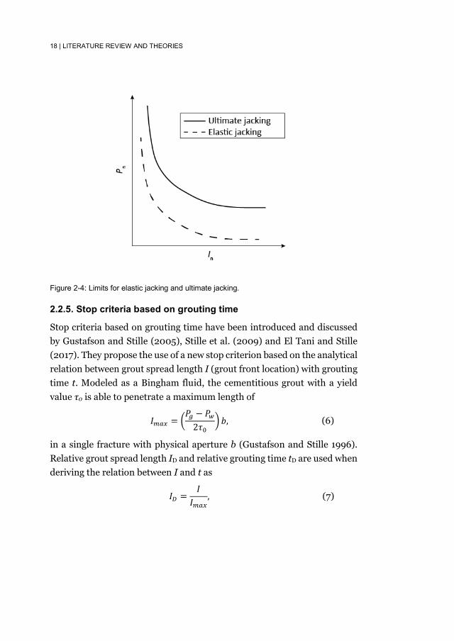
Ultimate jacking, on the other hand, means that the rock mass is jacked by the grouting pressure and the fracture is dilated irreversibly. Designers should avoid the ultimate jacking when determining the grouting pressure as it is uncontrollable. A normalized limit on ultimate jacking was also recommended by Stille et al. (2012) assuming horizontal fractures as
The jacking limits in Eqs. (1) and (5) are plotted in Figure 2-4. When grouting shallow fractures, the limit for ultimate jacking can be lower than the limit for elastic jacking due to the shallow overburden above the fracture. It should also be noted that the model for elastic jacking assumes that the rock mass above the fracture is mobilized elastically, which makes it questionable if the elastic jacking limits can be used for grouting in shallow rock mass without modification.
𝑃𝑃𝑛𝑛 +
𝑃𝑃𝑤𝑤3𝜌𝜌𝜌𝜌ℎ
≤𝑘𝑘
3𝐼𝐼𝑛𝑛+
13
, (1)
𝑃𝑃𝑛𝑛 +
𝑃𝑃𝑤𝑤𝜌𝜌𝜌𝜌ℎ
≤ 1 +1𝐼𝐼𝑛𝑛
+1
3𝐼𝐼𝑛𝑛2. (5)
18 | LITERATURE REVIEW AND THEORIES
Figure 2-4: Limits for elastic jacking and ultimate jacking.
2.2.5. Stop criteria based on grouting time
Stop criteria based on grouting time have been introduced and discussed by Gustafson and Stille (2005), Stille et al. (2009) and El Tani and Stille (2017). They propose the use of a new stop criterion based on the analytical relation between grout spread length I (grout front location) with grouting time t. Modeled as a Bingham fluid, the cementitious grout with a yield value τ0 is able to penetrate a maximum length of
in a single fracture with physical aperture b (Gustafson and Stille 1996). Relative grout spread length ID and relative grouting time tD are used when deriving the relation between I and t as
𝐼𝐼𝑚𝑚𝑎𝑎𝑚𝑚 = �
𝑃𝑃𝑔𝑔 − 𝑃𝑃𝑤𝑤2𝜏𝜏0
� 𝑏𝑏, (6)
𝐼𝐼𝐷𝐷 =
𝐼𝐼𝐼𝐼𝑚𝑚𝑎𝑎𝑚𝑚
, (7)
LITERATURE REVIEW AND THEORIES | 19
where μg is the viscosity of the grout. All the fractures (assumed as not interconnected) in a grouting section separated by packers share the same ID. The solution for the relation between ID and tD for a single fracture was derived by Gustafson et al. (2013). However, the solution cannot be explicitly solved. An approximation was made by Gustafson and Stille (2005) and was later modified by Stille et al. (2009) as
where θ for 1D flow is calculated as
and for 2D flow as
The analytical relations presented by Eqs. (10), (11) and (12) are unique regardless of different fracture properties and grouting properties. The analytical solution was later verified through experiments by Funehag and Thörn (2018). Different solutions were provided by Eriksson and Stille (2005) and El Tani (2012). However, the difference among the solutions is negligible (Stille 2015).
During the grouting process, directly measuring the grout spread can be difficult. Given the relations presented by Eqs. (10), (11) and (12) and the assumption that the fractures in a grouting section are not interconnected, the grouting time can be used as an indicator of whether the expected grout spread length has been obtained or not. However, a grouting section normally contains a large number of fractures with different apertures, many of which are too fine for the grout to penetrate. As can be observed from Eqs. (6) to (12), the grout penetrates further in
𝑡𝑡0 =
6(𝑃𝑃𝑔𝑔 − 𝑃𝑃𝑤𝑤)𝜇𝜇𝑔𝑔𝜏𝜏02
, (8)
𝑡𝑡𝐷𝐷 =
𝑡𝑡𝑡𝑡0
, (9)
𝐼𝐼𝐷𝐷 = �𝜃𝜃2 + 4𝜃𝜃 − 𝜃𝜃, (10)
𝜃𝜃1𝐷𝐷 =𝑡𝑡𝐷𝐷
2(0.6 + 𝑡𝑡𝐷𝐷), (11)
𝜃𝜃2𝐷𝐷 =𝑡𝑡𝐷𝐷
2(3 + 𝑡𝑡𝐷𝐷 + 0.23 ln 𝑡𝑡𝐷𝐷). (12)

20 | LITERATURE REVIEW AND THEORIES
fractures with larger aperture at the same grouting time. Therefore, Gustafson and Stille (2005) emphasized that the expected grout spread length in the finest groutable fracture within a section must be obtained to indicate the completion of the grouting process in the respective section. The corresponding grouting time becomes the stop criterion for this grouting section. If the expected spread requires a very long grouting time, the grouting pressure may be increased, or the design of the grout hole layout should be altered.
Based on the analytical solutions of grout spread length, the estimated injected volume Vtot can also be calculated as the sum of the grout take in all fractures. The flow rate Q is then estimated as dVtot/dt. The estimations of Vtot and Q are useful for estimating the cost. More importantly, they can be used to compare the measured flow rate/grout volume in real time to indicate behaviors such as hydraulic jacking (a sudden increase of flow rate, Stille et al. (2012)) or that the rock mass is fully sealed (zero flow rate). A zero flow rate could also indicate that the fractures have been clogged and the grout can no longer penetrate the fractures.
However, it should be kept in mind that the analytical solutions were developed based on a number of simplifications whereas the natural rock mass is more complex. This fact drives the efforts to develop numerical calculation methods to predict the grout spread during grouting. Mohajerani (2015) developed an algorithm which is able to model the gravitational effect in inclined or vertical fractures and to involve the time-dependent hardening of the grout. The two-phase flow model of grout in rock fractures from Zou et al. (2018) considered the existence of groundwater in saturated fractures and its influence. It was applied to a 2D fracture network by Zou et al. (2019). A conclusion made from the simulations was that the fracture distributions significantly influence the grout penetration.
2.2.6. Erosion of grout and fracture infilling materials
Fresh grout can get eroded during grouting when the grouting is performed in flowing groundwater. Axelsson (2009) investigated the mechanisms of erosion of fresh grout and the strategies that can be used to reduce the risk.
LITERATURE REVIEW AND THEORIES | 21
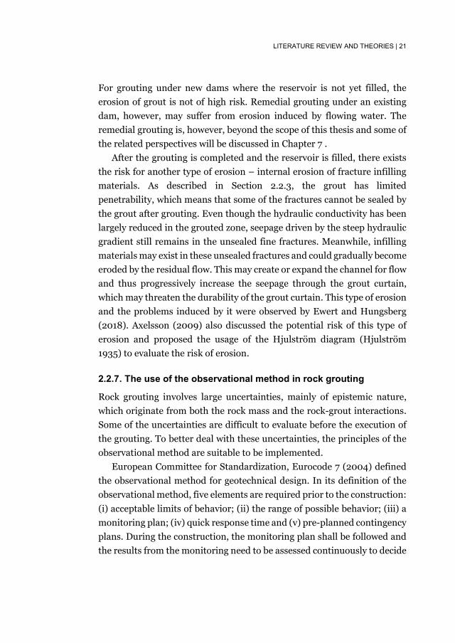
For grouting under new dams where the reservoir is not yet filled, the erosion of grout is not of high risk. Remedial grouting under an existing dam, however, may suffer from erosion induced by flowing water. The remedial grouting is, however, beyond the scope of this thesis and some of the related perspectives will be discussed in Chapter 7 .
After the grouting is completed and the reservoir is filled, there exists the risk for another type of erosion – internal erosion of fracture infilling materials. As described in Section 2.2.3, the grout has limited penetrability, which means that some of the fractures cannot be sealed by the grout after grouting. Even though the hydraulic conductivity has been largely reduced in the grouted zone, seepage driven by the steep hydraulic gradient still remains in the unsealed fine fractures. Meanwhile, infilling materials may exist in these unsealed fractures and could gradually become eroded by the residual flow. This may create or expand the channel for flow and thus progressively increase the seepage through the grout curtain, which may threaten the durability of the grout curtain. This type of erosion and the problems induced by it were observed by Ewert and Hungsberg (2018). Axelsson (2009) also discussed the potential risk of this type of erosion and proposed the usage of the Hjulström diagram (Hjulström 1935) to evaluate the risk of erosion.
2.2.7. The use of the observational method in rock grouting
Rock grouting involves large uncertainties, mainly of epistemic nature, which originate from both the rock mass and the rock-grout interactions. Some of the uncertainties are difficult to evaluate before the execution of the grouting. To better deal with these uncertainties, the principles of the observational method are suitable to be implemented.
European Committee for Standardization, Eurocode 7 (2004) defined the observational method for geotechnical design. In its definition of the observational method, five elements are required prior to the construction: (i) acceptable limits of behavior; (ii) the range of possible behavior; (iii) a monitoring plan; (iv) quick response time and (v) pre-planned contingency plans. During the construction, the monitoring plan shall be followed and the results from the monitoring need to be assessed continuously to decide

22 | LITERATURE REVIEW AND THEORIES
whether or not to apply the pre-planned contingency plans. By following the principles of the observational method, one can expect that the design can be adjusted according to instantaneous feedback during construction. In this way, the design is given a better flexibility to deal with less expected behaviors. Stille et al. (2012) also proposed that the principles of the observational method could be used for dam foundation grouting. However, the application of the observational method strictly following the definition in Eurocode 7 can be difficult to perform in practice (Spross 2014). Despite this challenge, based on a comparison between the remedial grouting execution under a Swedish dam with the principles of the observational method, Spross et al. (2016) suggested that the implementation of the observational method offers a sound framework for the safety management of remedial grouting.

THEORY-BASED DESIGN METHODOLOGY | 23
3. Theory-based design methodology
The research findings described in Section 2.2 have been widely applied in grouting projects for tunnels, especially in Sweden (Stille 2015). However, this is not the case for grout curtains under dams. In order to be able to implement the theories in the design of grout curtain under dams, a theory-based design methodology is needed. A theory-based design methodology for grout curtains under dams has therefore been developed within this project.
Figure 3-1 presents the flow chart of the proposed design methodology for grout curtains developed in this research project. It covers all phases of the design process, including the preliminary design, grouting execution and the dam safety management throughout the service life of the dam. In this thesis, a brief introduction of the methodology is presented, while the detailed introduction and the example of a design process can be found in the appended Paper B.
3.1. Preliminary design
Prior to each new grouting project, geological and hydrogeological investigations are vital for the understanding of the rock mass properties in the dam foundation. Based on interpretations of the results from water pressure tests and the rock mass quality, estimations of the fracture aperture distribution using the method described in Section 2.2.2 should be made. Geological domains should also be identified after the investigations and the grout curtain should be designed for each geological domain.

24 | THEORY-BASED DESIGN METHODOLOGY
Figure 3-1: Design flowchart for grout curtains under dams. Having the knowledge of the rock mass properties, the requirements on
the grout curtain needs to be defined. The target hydraulic conductivity
Geological and hydrogeologicalinvestigations
Define requirements ongrout curtain
Design of grout curtain
Design of grouting work
Execution of groutingfollowing the preliminary design
with proper monitoring
Grouting well executed?
Complete criteria fulfilled?
Analyze the reasons andapply contingency actions
Grout curtain constructed Long-termmonitoring
Remedialgrouting
Preliminary design
Position, thickness and depth of grout curtain
Grouting pressureStop criteriaGrout hole layoutContingency plans and complete criterion
Grouting execution
No
No
Yes Dam safety management
Hydraulic conductivity, uplift porepressure and internal erosion
Yes

THEORY-BASED DESIGN METHODOLOGY | 25
after grouting is recommended to be determined based on the suggestions from Houlsby (1990) as presented in Figure 2-1. Internal erosion of the fracture infilling materials needs to be prevented and the uplift reduction from the grout curtain shall be optimized, which constitute two additional requirements.
The next step in the methodology is the design of the grout curtain. Designers needs to determine the position and the geometry of the grout curtain after this step. The position, the length and depth of the grout curtain can still be designed empirically following the method from Section 2.1.2. It is the design of the thickness, however, that needs further consideration. In Paper A, a new definition of the thickness is suggested, defined as the thickness of the grout overlap between grout holes. The paper also described the procedure of designing the optimum thickness of a grout curtain. The design procedure takes into account the three requirements on the grout curtain: (i) the required hydraulic conductivity of the rock mass in the curtain, (ii) prevention of erosion of fracture infilling materials and (iii) uplift pore pressure reduction.
While developing the design of the thickness of the grout curtain, it was found that there is a lack of research on the erosion of fracture infilling materials. Paper A provides some preliminary discussion over this issue. After flushing the grout holes to remove infilling materials, three scenarios may exist in the fractures: (i) infilling materials completely flushed away, (ii) fracture fully filled by the infilling materials, and (iii) fracture partly filled by the infilling materials, as shown in Figure 3-2. Among these scenarios, the partly filled fractures are those of primary concern. Large openings in these fractures may later be sealed by the grout, whereas the smaller openings remain open after grouting, providing channels for remaining flow. Compared to the fully filled fractures and the possible seepage flow between particles, the channel flow in partly filled fractures may erode the infilling materials more easily. In other words, the partly filled fracture is a step in advance of a fully filled fracture before the seepage flow creates channels in the fully filled fracture. The material that is believed to have the greatest risk of being eroded is fine sand, since coarser materials are estimated to be penetrated by the grout and finer

26 | THEORY-BASED DESIGN METHODOLOGY
Figure 3-2: Fracture infilling scenarios after flushing: (a) completely flushed, (b) fully filled and (c) partly filled (from Paper A).
cohesive soils require higher velocities to become eroded due to the adhesive forces between the particles (Hjulström 1935). To improve the knowledge on the erosion of fracture infilling materials and establish a clear critical condition for the initiation/prevention (they share the same boundary) of the erosion, Paper C investigated the critical condition of the incipient motion for sand infillings in a rock fracture using coupled CFD-DEM analyses. The results from this work show that the use of the Hjulström diagram (Hjulström 1935) and Shields diagram (Shields 1936) to estimate the critical condition for the erosion of infilling materials may not be suitable.
In the design, it is important to differentiate between the design of the grout curtain and the following step, the design of the grouting work. The major purpose of the design of the grout curtain is to fulfill the requirements defined for the grout curtain, whereas the purpose of the design of the grouting work is to obtain the designed grout curtain by determination of suitable values on the grouting parameters. Designers need to: (i) choose a suitable grout and grout mix (following Section 2.2.3); (ii) select grouting pressures for different depths to provide sufficient grout spread length while avoiding hydraulic jacking (following Section 2.2.4); (iii) determine the stop criterion based on grouting time (following Section 2.2.5); (iv) design the grout hole layout to obtain the designed thickness; (v) prepare the contingency plans for potential unexpected behaviors during grouting (following Section 2.2.7) and establish the completion criterion to indicate the completion of the grouting project. Among these parameters, the grouting pressure, stop criteria and grout hole layout may

THEORY-BASED DESIGN METHODOLOGY | 27
need to be determined iteratively. By the end of this step, a complete grouting plan will be established.
3.2. Grouting execution
Grouting will be executed following the preliminary design. During the grouting process, the grouting operators needs to perform the grouting with satisfactory standard. Efficient work, good organization, following the preliminary design, and quick and effective reflection upon unexpected events constitutes the satisfactory grouting standard. Competent grouting operators with extensive experience and good understanding of rock grouting are generally preferred to perform the grouting. Good judgement is also preferred. Unexpected behaviors need to be discovered quickly and the respective contingency plans should be put in place in time.
3.3. Dam safety management
Long-term indirect monitoring is required after the grout curtain is completed, especially for the dams with high importance and failure consequences. Pore pressure changes in the rock mass at different locations may reflect the functionality of the grout curtain. If the measured pore pressure in the grouted zone is observed to increase, the grout curtain may be suffering from degradation. Remedial actions need to be put in place when the degradation becomes so severe that alarming thresholds for the pore pressure are reached. Remedial grouting is one of the actions that can be undertaken to repair the degraded grout curtain.


SUMMARY OF APPENDED PAPERS | 29
4. Summary of appended papers
4.1. Paper A: On the required thickness of grout curtains under dams
Suihan Zhang & Fredrik Johansson In: ICOLD Symposium on Sustainable Development of Dams and River Basins, New Delhi, 24th - 27th February, 2021. INCOLD. The determination of the thickness of grout curtains has long been an empirical technique. This paper presents a theory-based methodology to determine the thickness of the grout curtains under dams after providing an explicit definition of the required thickness of the grout curtain. The presented methodology is based on three requirements on the curtain, all related to the thickness: the required hydraulic conductivity of the rock mass in the curtain, prevention of erosion of fracture infilling materials and uplift pore pressure reduction. After fulfilling these three requirements, the required thickness of the curtain can be determined. A design example on a fictitious dam is presented to illustrate the methodology. The requirement related to erosion of fracture infilling material highlights the importance of having knowledge on the critical conditions for initiation of erosion, which is further studied in Paper C. Using the developed methodology will result in better durability of the grout curtain as well as less risk of sliding instability of the dam.

30 | SUMMARY OF APPENDED PAPERS
4.2. Paper B: Design methodology for grout curtains under dams founded on rock
Suihan Zhang, Fredrik Johansson & Håkan Stille Submitted to Geotechnical and Geological Engineering. This paper develops a theory-based design methodology for grout curtains under new dams. The methodology consists of a design framework for grout curtains. State-of-the-art theories on rock grouting are incorporated in the framework with consideration of the requirements on the grout curtain under dams. Compared to the conventional empirical design approach, the methodology presented in this paper considers the grout curtain as a structural component of the dam in its rock foundation. The new methodology contains analytical calculations and implements a stop criterion based on grouting time. With the estimated grout spread, the grout hole layout can be designed accordingly. The uncertainties of the design are dealt with by applying the principles of observational method. The new design methodology contributes to a higher grouting efficiency. With a clear analytical estimation of the grouting process, it is also easier to prevent and detect unexpected behaviors during grouting.
4.3. Paper C: Numerical modelling of incipient motion of fracture infillings
Penghua Teng, Suihan Zhang & Fredrik Johansson Submitted to International Journal of Rock Mechanics and Mining Sciences. Infillings in rock fractures can potentially be eroded due to groundwater flow. This problem is of importance for the durability of the grout curtain. This paper investigates the critical condition for incipient motion of
SUMMARY OF APPENDED PAPERS | 31
fracture infillings. To simulate the scenario of partly filled fractures, a 3D fracture model with rough walls and a 3D parallel-plate model with smooth walls are constructed, both having sand particles evenly distributed at the bottom of the model. One-dimensional flow with various velocities is then introduced into the model. The flow to particle and particle to particle interactions are simulated based on a coupled Computational Fluid Dynamics (CFD)-Discrete Element Method (DEM) approach. The critical conditions are captured by observations of the particles’ movement. Results from the rough-wall model and the parallel-plate model show different critical velocity, which indicates that the fracture geometry influences the critical conditions for incipient motion. The results are further compared with the well-known Hjulström diagram and Shields diagram. The comparison shows that discrepancies exist, which implies that it is not suitable to predict the incipient motion of fracture infillings using the two diagrams. However, a better agreement is found between the results and an equation derived by White, indicating the potential of using this equation to estimate the critical conditions of erosion of fracture infillings. This study visualizes and quantitatively analyzes the incipient motion of fracture infillings and provides a valuable reference for the determination of the threshold of incipient motion of fracture infillings.


DISCUSSION | 33
5. Discussion
5.1. Empirical knowledge
In any subject within the field of rock engineering, it is naive to rule out the empirical knowledge and turn to a completely theoretical/analytical approach. The extensive uncertainties incorporated in the rock mass make it nearly impossible to perform the design following the same manner as structures above the surface. The same applies to rock grouting, especially the design of grout curtains.
The methodology proposed in this thesis is theory-based yet not complete. A number of aspects in the design still favor the rich knowledge from experienced grouting engineers. Throughout the preliminary design phase, the analytical calculations provide an explicit design reference while the empirical knowledge can be used to assess the design and provide suggestions for improvement. In this phase, the selection of the grout material, grout mix, equipment, the starting grouting pressure for calculation etc. are still dependent on the empirical knowledge. The application of the principles of the observational method requires extensive experience to prepare monitoring plans, suitable acceptance criteria and the corresponding contingency plans. During the grouting execution, the monitoring data needs to be interpreted wisely. Quick and precise judgements are the products of rich grouting experience and good understanding of the grouting process.
5.2. Advantages with the suggested design methodology
The proposed design methodology provides good flexibility to the design. A certain thickness of the grout curtain can be obtained by various combinations of grout hole layout and stop criteria. Essentially, as long as
34 | DISCUSSION
the calculated overlapping (according to Section 2.2.5) fulfills the designed thickness, two directions can be followed: (i) shorter distances between holes, shorter grouting time and shorter grout spread; (ii) longer distances between holes, longer grouting time and longer grout spread. Assume for the same grout curtain to be constructed that both options implement the same grouting pressure and managed to fulfill the jacking requirements. For option (i) the results would be a relatively large number of grout holes needed to be drilled with smaller spacing between them. However, the time required to grout each hole is shorter. For option (ii), the results on the contrary would be a smaller number of grout holes needed to be drilled, with larger spacing while the time to grout each hole is longer. Intuitively, neither of the option stands out as a better strategy. The choice should depend mainly on the interest of the designers and the other parties involved in the project. Overall time/cost evaluation needs to be performed based on specific conditions, and the proposed methodology facilitates the time/cost evaluation. For example, if drilling grout holes is relatively easy and cheap, it may not be efficient to grout for a long time to get a longer spread. The grout spread will be significantly slower after long grouting time than in the beginning of a grout run. Efficiency of the grouting will be sacrificed with a long grouting time, while only expecting minor increase in grout spread. Drilling more holes under this condition could be more cost-effective compared to grouting for longer time. However, if drilling grout holes are difficult and expensive in a project, the second option can become favorable.
Analytical calculations in the design methodology facilitate sensitivity analyses of the important factors incorporated in the design process. In this way, the designers are able to locate the parameters which can significantly influence the quality of the grout curtain and the process of the grouting work. Extra attention needs to be paid on these factors when performing the design. For example, in Paper B, a sensitive analysis is performed on the residual conductivity after grouting from various related coefficients. The results indicate that the choice of these coefficients significantly affects the residual conductivity. It emphasizes the importance of thorough geological and hydro-geological investigations. The parameter bcrit also has

DISCUSSION | 35
significant effects on the residual conductivity of the grout curtain and on the grout spread length as shown in Eq. (6). As a result, the choice of the grout materials, as well as the design of the grout mix, are of great importance when performing the preliminary design. By estimating the possible variation of the bcrit, the variation of the residual hydraulic conductivity and the possible grout spread length can be estimated.
The overall design flowchart presented in Figure 3-1 constitutes the framework for a potential design algorithm and the theory-based analytical calculations can be performed with the aid of computers. Design aided by computer can effectively reduce the calculation time, especially when iterations are needed to design the stop criteria, grout hole layout and the grouting pressure. Visualization of the obtained results can further help the designers to obtain better understanding of the design.
The current computers are capable of collecting, visualizing large amount of real-time data from the site investigations and the grouting process (Tsuji et al. 2012). With the development of machine learning and artificial intelligence, it is expected that the computer will be trained to even interpret the real-time data and provide suggestions on design or reactions.
5.3. Limitations with the suggested design methodology
The developed design methodology consists of rock grouting theories which are based upon several simplifying assumptions. These simplifications make the design product unable to reflect the real grout curtain under a dam. Therefore, the suggestion from the author is that the design product should be considered as a basic design. This basic design should be further assessed and modified if necessary before and during the grouting execution. When the real condition is beyond simplification, e.g. poor rock mass properties, vertical fracture patterns, karst beneath the dam etc., empirical knowledge should be treasured to fill the gap as discussed in Section 5.1, and the principles of the observational method should be applied to deal with these complex conditions.

36 | DISCUSSION
One of the fundamental assumptions of the theory-based design is that the grouting execution is capable of following the grouting work design and obtaining the same grouting results as the design, i.e. grouting pressure, grout spread length etc. High grouting standard is an underlying presumption. If the standard of grouting cannot be guaranteed, conservative design may be needed to compensate, and strict acceptance criteria and contingency actions should be put in place with frequent supervision.
Finally, the design methodology proposed in this thesis is not a fixed guideline to be strictly followed. Updates are not only possible but welcomed. The design framework provides the “skeleton” and it is the rock grouting theories that are filling this “skeleton”. Limitations in the theories create large potential for the theories to evolve. The current research efforts on rock grouting will constantly drive the improvement of the design methodology by replacing the past theories with more accurate ones, which creates a more dynamic methodology.
5.4. Erosion of infilling materials
Paper C investigates the incipient motion of sand infillings in fractures and suggests that it can be inappropriate to use the Hjulström diagram and Shields diagram to estimate the initiation of the internal erosion. Instead, the numerical results show good agreements with the equation for the incipient motion of rounded sand particles derived from flume experiments under laminar flows by White (1940):
where τwc is the critical shear stress from water to initiate the incipient motion of the sand particles, ρs is the density of the sand particles, ρw is the density of water, D is the diameter of the sand particles and θ is the repose angle of the sand submerged in fluid.
However, one needs to link the shear stress to the hydraulic gradient or mean velocity in order to use Eq. (13) to estimate the critical hydraulic gradient/critical mean velocity regarding the erosion of fracture infilling
𝜏𝜏𝑤𝑤𝑎𝑎 = 0.18(𝜌𝜌𝑠𝑠 − 𝜌𝜌𝑤𝑤)𝜌𝜌𝑔𝑔𝑡𝑡𝑔𝑔𝑔𝑔𝜃𝜃, (13)

DISCUSSION | 37
materials. First, the relationship between the mean velocity vm and the hydraulic gradient i in a rectangular channel is expressed as
where bh is the hydraulic aperture of the existing open channels in partly
filled fractures, μ is the viscosity of water (1.3∙10-3 Pas at 10°C). The shear
stress τw acting on the channel boundaries from the flowing water can be calculated as
By setting τwc in Eq. (13) equal to τw in Eq. (15), the critical hydraulic gradient, ic to initiate the erosion of sand infillings can be derived as
The corresponding critical mean velocity, vc can be calculated from ic following Eq. (14).
For fine sand with diameters between 0.02 mm to 0.2 mm, the density is taken as 2650 kg/m3 and tanθ is taken as 1 according to the tests by White (1940). Figure 5-1 presents the linear relationship between vm and i from Eq. (14) for various bh, together with the critical conditions (ic and vc) for particle diameters of 0.2 mm and 0.02 mm calculated from Eq. (16). In Figure 5-1, the gradient or velocity in the area above/on the right to the critical conditions can potentially initiate the erosion of fine sand with corresponding particle diameters. It should be noted that if the particle diameter is larger than bh, as presented by the dashed curves in Figure 5-1, such particles might get clogged despite that their incipient motion has been initiated by the flow. Therefore, erosion is unlikely to occur when D is larger than bh. This figure can be used as a rough estimation of the critical hydraulic gradient/critical velocity for fine sand. However, experimental tests and further numerical analyses are needed to verify this figure.
It can be observed from Figure 5-1 that when large ungrouted fractures exist, it can be difficult to prevent the erosion of fine sand in the grouted zone by simply designing a thick grout curtain as the hydraulic gradient in
𝑣𝑣𝑚𝑚 =𝜌𝜌𝑤𝑤𝜌𝜌12𝜇𝜇
𝑏𝑏ℎ2 ∙ 𝑖𝑖, (14)
𝜏𝜏𝑤𝑤 =𝜌𝜌𝑤𝑤𝜌𝜌
2𝑏𝑏ℎ ∙ 𝑖𝑖. (15)
𝑖𝑖𝑎𝑎 =2 ∙ 0.18(𝜌𝜌𝑠𝑠 − 𝜌𝜌𝑤𝑤)𝑔𝑔𝑡𝑡𝑔𝑔𝑔𝑔𝜃𝜃
𝜌𝜌𝑤𝑤𝑏𝑏ℎ. (16)

38 | DISCUSSION
Figure 5-1: Critical hydraulic gradient/critical mean velocity for fine sand with particle diameter of 0.2 mm and 0.02 mm under various remaining channel apertures. The curves of critical conditions are dashed when the particle diameter is larger than the remaining aperture.
this zone is usually higher than the critical value according to Figure 5-1. Under such conditions, the grout curtain can be marked as prone to erosion of infilling materials, if such exists in the fractures.
If erosion of the fracture infilling materials is difficult to prevent, one option could be to flush the grout holes before grouting, aiming to leave as little remaining infilling materials in the fracture as possible. The extent of the erosion could be reduced in this way. Once the dam is taken into operation, a strict monitoring plan shall be implemented according to the principles of the observational method, where contingency actions for increased seepage as a result of erosion shall be prepared, including remedial grouting and other measures. They should be executed when signs of grout curtain deterioration are observed.
CONCLUSIONS | 39
6. Conclusions
Conventional empirical design methods of grout curtains require extensive experience to avoid inadequate or over-conservative design. The risk of internal erosion of fracture infilling materials is not directly accounted for, which potentially could accelerate the deterioration of the grout curtain. Furthermore, the stop criterion in the empirical methods, i.e. “refusal”, may require long grouting time and high costs without resulting in equivalently better grouting quality. The efficiency of this stop criterion is therefore doubtful. The conventional selection of grouting pressure is also based on “rules of thumb”, which introduces the risk of jacking of the rock mass.
To overcome the limitations of the empirical design methods and fill the gap between the grouting theories and the practical design, a theory-based design methodology for grout curtains under new dams is proposed in this thesis (Paper A and B). The methodology consists of three phases: preliminary design, grouting execution, and dam safety management. The grout curtain is designed based on the geological and hydrogeological conditions of the site, with the primary focus to reduce the seepage through the rock mass, prevent the erosion of any fracture infilling materials and optimize the reduction in uplift pressure. To obtain the designed grout curtain geometry, the grouting work needs to be designed based on the grouting theories. The design methodology uses the principles of the observational method to handle uncertainties in expected behavior during the grouting execution and the time of operation for the dam.
The prevention of erosion of fracture infilling materials is studied in Paper C. The results from the numerical simulations imply that the usage of the Hjulström diagram and the Shield’s diagram, may be inaccurate when estimating the incipient motion of fracture infilling materials. An equation suggested by White shows better agreement with the results. The

40 | CONCLUSIONS
White’s equation could therefore potentially provide better estimation when evaluating the incipient motion/erosion of the fracture infilling materials.
Despite the existing limitations of the proposed methodology, it is believed that a better durability of the grout curtains can be obtained by applying the suggested design methodology and accounting for the critical conditions regarding the erosion of fracture infilling materials.

SUGGESTIONS FOR FUTURE WORK | 41
7. Suggestions for future work
The proposed design methodology creates a framework for the design of grout curtains, but new progress in the field of rock grouting is always welcomed to replace the old theories and improve the overall design methodology. The author hereby offers suggestions on the topics that potentially can be investigated further. With respect to determining the thickness of the grout curtain, the author suggested further experimental studies on the erosion of fracture infillings to compare against the numerical results from Paper C. Clear thresholds that can be universally applied to fractures of different geometries is yet to be derived. It is also suggested that grout penetration can be further studied. Currently, grout penetration was mainly studied based on horizontal fractures, whereas the penetration in vertical fractures can be influenced by gravity. Further studies on these topics are needed to extend the design to cover more geological conditions, which can reduce the amount of simplifications and make the methodology more robust.
The design methodology proposed in this thesis has not been applied to a real grouting project to verify its applicability. The author believes that a case study on a dam foundation grouting project, which follows this methodology, would be valuable. A case study on a dam foundation grouting project is therefore considered as an important future work.
Finally, most dams in Sweden were built around the construction peak in the 1920’s and also in the 1950’s, 60’s and 70’s. Some dams are now over 100 years old, with an average age of 83 years (Bernstone 2006). Sweden is now facing a situation with a population of old dams, which is shared with many other western countries. Currently, no new dams are being constructed or planned in Sweden (Zarfl et al. 2014). In Sweden, the demands in grouting may instead shift from constructing new grout curtains to repairing the existing ones, whereas the design methodology

42 | SUGGESTIONS FOR FUTURE WORK
present in this thesis focuses on the design of grout curtain under new dams. The shifts in demands of grout curtains suggest new research topics on repairing the existing grout curtains for old dams.
More research is needed on the monitoring and assessment of existing grout curtains. Both the techniques for evaluating the data as well as new techniques for monitoring the grouted zone are needed. This can improve the assessment of the degradation of the grout curtain and enable the identification of degraded zones.
When signs of degradation are observed, remedial measures including remedial grouting should be implemented to repair the grout curtain. Remedial grouting under operating dams, although sharing similar principles with grouting under new dams, faces different challenges, one of which is to grout against flowing water. A degraded grout curtain has limited capability to reduce seepage under the dam. Consequently, the groundwater velocity in the fractures could be so high that the fresh grout may become eroded. To overcome this challenge, and to perform the remedial grouting with satisfying quality, a design method specifically derived for remedial grouting needs to be developed. Future research on the design of remedial grouting is thus desired.

REFERENCES | 43
References Axelsson, M. 2009. "Prevention of Erosion of Fresh Grout in Hard Rock."
Doctoral thesis, Department of Civil and Environmental Engineering, Chalmers University of Technology.
Bernstone, C. 2006. "Automated performance monitoring of concrete dams." Doctoral Thesis Lund University.
Bonin, G., Rombough, V., Carter, T., Jefferies M. 2012. "Towards Better Injection Control and Verification of Rock Grouting." International Conference of Grouting and Deep Mixing, New Orleans.
Brantberger, M., Stille, H., Eriksson, M. 2000. "Controlling grout spreading in tunnel grouting — analyses and developments of the GIN-method." Tunnelling and Underground Space Technology Vol. 15 (No. 4):343-352. doi: 10.1016/S0886-7798(01)00003-7.
Cambefort, H. 1977. "The principles and applications of grouting." Quarterly Journal of Engineering Geology and Hydrogeology Vol. 10 (No. 2):57-95. doi: 10.1144/GSL.QJEG.1977.010.02.01.
Canadian Dam Association (CDA). 2007. Geotechnical Considerations for Dam Safety. Technical Bulletin. Toronto: Canadian Dam Association.
Casagrande, A. 1961. "Control of Seepage through Foundations and Abutments of Dams." Géotechnique 11 (No. 3):161-182. doi: 10.1680/geot.1961.11.3.161.
Draganović, A., Stille, H. 2011. "Filtration and penetrability of cement-based grout: Study performed with a short slot." Tunnelling and Underground Space Technology 26 (No. 4):548-559. doi: 10.1016/j.tust.2011.02.007.
Eklund, D., Stille, H. 2008. "Penetrability due to filtration tendency of cement-based grouts". Tunnelling and Underground Space Technology, Vol. 23 (4):389-398. doi:10.1016/j.tust.2007.06.011

44 | REFERENCES
El Tani, M. 2012. "Grouting rock fractures with cement grout." Rock Mechanics and Rock Engineering Vol. 54 (4):547-561. doi: 10.1007/s00603-012-0235-0.
El Tani, M., Stille, H. 2017. "Grout Spread and Injection Period of Silica Solution and Cement Mix in Rock Fractures." Rock Mechanics and Rock Engineering Vol. 50 (9):2365–2380. doi: 10.1007/s00603-017-1237-8.
Eriksson, M., Stille, H. 2003. "A Method for Measuring and Evaluating the Penetrability of Grouts." Third International Conference on Grouting and Ground Treatment, New Orleans.
European Committee for Standardization. 2004. Eurocode 7: Geotechnical design – part 1: General rules. Brussels: European Committee for Standardization.
Ewert, F. 1985. Rock Grouting with Emphasis on Dam Sites. Berlin: Springer-Verlag.
Ewert, F.K., Hungsberg, U. 2018. Rock Grouting at Dam Sites. Cham: Springer.
Federal Energy Regulatory Commission (FERC). 2016. Engineering Guidelines for the Evaluation of Hydropower Projects: 3 Revised Chapter 3 – Gravity Dams. Washington: Federal Energy Regulatory Commission.
Funehag, J., Thörn, J. 2018. "Radial penetration of cementitious grout – Laboratory verification of grout spread in a fracture model." Tunnelling and Underground Space Technology Vol. 72:228-232. doi: 10.1016/j.tust.2017.11.020.
Gothäll, R., Stille, H. 2009. "Fracture dilation during grouting." Tunnelling and Underground Space Technology Vol. 24:126-135. doi: 10.1016/j.tust.2008.05.004.
Gustafson, G., Stille, H. 1996. "Prediction of groutability from grout properties and hydrogeological data." Tunnelling and Underground Space Technology Vol. 11 (No. 3):325-332. doi: 10.1016/0886-7798(96)00027-2.

REFERENCES | 45
Gustafson, G., Stille, H. 2005. "Stop criteria for cement grouting." Felsbau : Zeitschrift für Geomechanik und Ingenieurgeologie im Bauwesen und Bergbau Vol. 25 (No. 3):62-68.
Gustafson, G. 2012. Hydrogeology for Rock Engineers. Stockholm: BeFo-Rock Engineering Research Foundation.
Gustafson, G., Claesson, J., Fransson, Å. 2013. "Steering Parameters for Rock Grouting." Journal of Applied Mathematics Vol. 2013:1-9. doi: 10.1155/2013/269594.
Håkansson, U. 1993. "Rheology of Fresh Cement-Based Grouts." Doctoral thesis, Royal Institute of Technology.
Hernqvist, L., Einarsson, V., Höglund, A. 2014. "Does one fracture dominate the borehole transmissivity." Swedish Rock Mech. Meeting, Stockholm.
Hjulström, F. 1935. "Studies of the Morphological Activity of Rivers as Illustrated by the River Fyris." Doctoral thesis, Uppsala University.
Holmberg, M., Tsuji, M., Stille, B., Stille, H. 2012. "Evaluation of Pre-grouting For the City Line Project Using the RTGC Method." ISRM International Symposium - EUROCK 2012, Stockholm.
Houlsby, A.C. 1990. Construction and Design of Cement Grouting. New York: John Wiley and Sons.
Lancaster-Jones, P.F.F. 1975. "The interpretation of the Lugeon water-test." Quarterly Journal of Engineering Geology and Hydrogeology Vol. 8(2):151-154. doi: 10.1144/GSL.QJEG.1975.008.02.05.
Littlejohn, G. S. 1982. "Design of Cement Based Grouts." Grouting in Geotechnical Engineering, New Orleans.
Lombardi, G., Deere, D. 1993. "Grouting Design and Dontrol Using the GIN Principle." International Water Power and Dam Construction Vol. 45 (No. 6):15-22.
Mitchell, J.K. 1981. "Soil improvement-State of the art report." International Conference on Soil Mechanics and Foundation Engineering, Stockholm.

46 | REFERENCES
Mohajerani, S., Baghbanan, A., Bagherpour, R., Hashemolhosseini, H. 2015. "Grout penetration in fractured rock mass using a new developed explicit algorithm." International Journal of Rock Mechanics & Mining Sciences Vol. 80:412-417. doi: 10.1016/j.ijrmms.2015.06.013.
Rafi, J.Y., Stille, H. 2014. "Control of rock jacking considering spread of grout and grouting pressure." Tunnelling and Underground Space Technology Vol. 40:1-15.
Rafi, J.Y., Stille, H. 2015a. "Basic mechanism of elastic jacking and impact of fracture aperture change on grout spread, transmissivity and penetrability." Tunnelling and Underground Space Technology Vol. 49:174-187. doi: 10.1016/j.tust.2015.04.002.
Rafi, J.Y., Stille, H. 2015b. "Applicability of Using GIN Method, by Considering Theoretical Approach of Grouting Design." Geotechnical and Geological Engineering Vol. 33:1431–1448. doi: 10.1007/s10706-015-9910-8.
Ruggeri, G. 2004. Uplift Pressures Under Concrete Dams: Final Report. ICOLD European Club.
Shields, A. 1936. "Application of Similarity Principles and Turbulence Research to Bed-Load Movement". Hydrodynamics Laboratory, California Institute of Technology, Pasadena (English translation).
Spross, J. 2014. "A Critical Review of the Observational Method." Licentiate thesis, KTH-Royal Institute of Technology.
Spross, J., Johansson, F., Uotinen, L.K.T., Rafi, J.Y. 2016. "Using Observational Method to Manage Safety Aspects of Remedial Grouting of Concrete Dam Foundations." Geotechnical and Geological Engineering Vol. 34:1613–1630. doi: 10.1007/s10706-016-0069-8.
Statens Vattenfallsverk. 1968. Anvisningar för utförande av cementinjektering i berg. Stockholm: Statens Vattenfallsverk.

REFERENCES | 47
Stille, B., Stille, H., Gustafson, G., Kobayashi, S. 2009. "Experience with the real time grouting control method." Geomechanics and Tunnelling Vol. 2 (No. 5). doi: 10.1002/geot.200900036.
Stille, H., Gustafson, G., Hässler, L. 2012. "Application of New Theories and Technology for Grouting of Dams and Foundations on Rock." Geotechnical and Geological Engineering Vol. 30:603-624. doi: 10.1007/s10706-012-9512-7.
Stille, H. 2015. Rock Grouting - Theories and Applications. Stockholm: BeFo-Rock Engineering Research Foundation.
Swedenergy. 2020a. RIDAS – Energiföretagens riktlinjer för dammsäkerhet, Tillämpningsvägledning Kapitel 9: Grundläggning (Swedish Hydropower Companies' Guidelines for dam safety). Stockholm: Swedenergy AB.
Swedenergy. 2020b. RIDAS – Energiföretagens riktlinjer för dammsäkerhet, Tillämpningsvägledning Kapitel 9: Betongdammar (Swedish Hydropower Companies' Guidelines for dam safety). Stockholm: Swedenergy AB.
Tsuji, M., Holmberg, M., Still, B., Rafi, J.Y., Stille, H. 2012. Optimization of the grouting procedure with RTGC method. Data from a trial grouting at city line project in Stockholm, SKB R-12-16 Stockholm: Svensk Kärnbränslehantering AB (SKB).
Weaver, K.D., Bruce, D.A. 2007. Dam Foundation Grouting, Revised and Expanded Edition. Reston: American Society of Civil Engineers (ASCE).
White, C.M. 1940. "The equilibrium of grains on the bed of a stream." Proceedings of the Royal Society A Vol. 174:322–338. doi: doi.org/10.1098/rspa.1940.0023.
World Commission on Dams. 2000. Dams and development: A new framework for decision-making: The report of the world commission on dams. London: Earthscan.
Zarfl, C., Lumsdon, A., Berlekamp, J., Tydecks, L., Tockner, K. 2014. "A Global Boom in Hydropower dam Construction." Aquatic Sciences Vol. 77(1):161-170. doi: 10.1007/s00027-014-0377-0.

48 | REFERENCES
Zimmerman, R.W., Bodvarsson, G.S. 1996. "Hydraulic Conductivity of Rock Fractures." Transport in Porous Media Vol. 23:1-30. doi: 10.1007/BF00145263.
Zou, L., Jing, L., Cvetkovic, V. 2015. "Roughness decomposition and nonlinear fluid flow in a single rock fracture." International Journal of Rock Mechanics & Mining Sciences 75:102-118. doi: 10.1016/j.ijrmms.2015.01.016.
Zou, L., Håkansson, U., Cvetkovic, V. 2018. "Two-phase cement grout propagation in homogeneous water-saturated rock fractures." International Journal of Rock Mechanics and Mining Sciences Vol. 106:243-249. doi: 10.1016/j.ijrmms.2018.04.017.
Zou, L., Håkansson, U., Cvetkovic, V. 2019. "Cement grout propagation in two-dimensional fracture networks: Impact of structure and hydraulic variability." International Journal of Rock Mechanics and Mining Sciences Vol. 115:1-10. doi: 10.1016/j.ijrmms.2019.01.004.


