8
L1000V L1000V L1000V L1000V L1000V LIFT INVERTER SERIES L1000V EN DE ES FR IT
L1000V
L1000V
L1000VL1000V
L1000V
LIFT InvErTEr SErIESL1000V
En
DE
ES
Fr
IT
Literature No. YEG_INV_L1000V_EN_v2_0310Printed in Germany, March 2010
2 YASKAWA L1000V
W
H
W1
H1
H2
D
t14-M4
Content
Content
Experience & Innovation
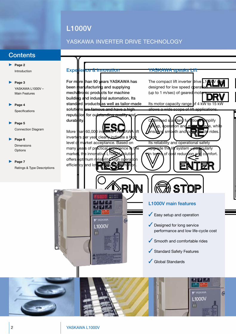
For more than 90 years YASKAWA has been manufacturing and supplying mechatronic products for machine building and industrial automation. Its standard products as well as tailor-made solutions are famous and have a high reputation for outstanding quality and durability.
More than 60,000 installed YASKAWA lift inverters per year clearly indicate a high level of market acceptance. Based on many years of practical experience in the market, the innovative L1000V solution offers optimum reliability, high operation efficiency and low energy consumption.
YASKAWA speaks Lift
The compact lift inverter drive L1000V was designed for low speed operation (up to 1 m/sec) of geared motors.
Its motor capacity range of 4 kW to 15 kW allows a wide scope of lift applications.
Optimised standard functions simplify set-up, operation and maintenance, while ensuring smooth and comfortable rides.
Its reliability and operational safety upgrade the lift system – particularly in terms of cost reduction and comfort.
Page 2
Introduction
Page 3
YASKAWA L1000V –
Main Features
Page 4
Specifications
Page 5
Connection Diagram
Page 6
Dimensions Options
Page 7
Ratings & Type Descriptions
Contents
L1000v main features
9 Easy setup and operation
9 Designed for long service performance and low life-cycle cost
9 Smooth and comfortable rides
9 Standard Safety Features
9 Global Standards
L1000v
YASKAWA INVERTER DRIVE TECHNOLOGY

3
W
H
W1
H1
H2
D
t14-M4
YASKAWA L1000v – MAIn FEATurES
THE LIFT InvErTEr DrIvE For opEn-Loop AppLICATIonS
Easy setup and operation
New motor Auto-Tuning features - Stationary Auto-Tuning for
modernisation applications - Rotational Auto-Tuning for high
accuracy motor tuning
Inverter software designed to support all common lift controllers in the market
The L1000V speaks the language of the lift experts (monitoring in Hz, m/s, rpm, levelling speed, service speed, nominal speed)
Quick and easy drive replacement due to multifunctional terminal block with parameter backup feature
DriveWizardPlus: Software tool to support the user in storing and organising parameters
Optional LCD operator for simple operation including copy function for saving drive settings.
Also available: a USB Copy Unit offering a fast and convenient way to carry out instant programming of a large number of inverter drives with identical parameter settings
Designed for long service performance and low life-cycle cost
Advanced IGBT protection ensures three million starts at 165% output current.
Cooling fan and capacitors designed for more than 70,000 hrs of maintenance-free operation
Performance Life Monitors for IGBT, cooling fan and capacitors.
Only one motor contactor needed due to integrated functional safety feature (in compliance with EN81-1)
Two relay outputs for fault and brake control reduce installation effort and costs.
The size of the UPS (Uninterrupted Power Supply) is reduced by a light load function - in case of power loss emergency, the L1000V detects the light load direction of the lift.
Smooth and comfortable rides
Specialized lift software based on many years of modernisation experience ensures smooth and quiet operation in passenger elevators.
Simple and efficient brake sequence for smooth operation.
High leveling accuracy even in open-loop, thanks to load detection during run
Five independent settings of S-Curves to prevent jerks
Built-in optional feature: pulse input feedback with PG to increase levelling accuracy
Global Standards
CE Directive 2006/95/EC: EN61800-5-1:2003, EN50178:1997
EMC Directive 2004/108/EC: EN61800-3:2004
Lift: EN12015:2004 (with option), EN12016:2004
Standard Safety Features
IEC 60204-1 Safe Torque Off (STO) functional safety
ISO1384 9 1:2009 Performance Level C
IEC/EN61508 SIL2
4 YASKAWA L1000V
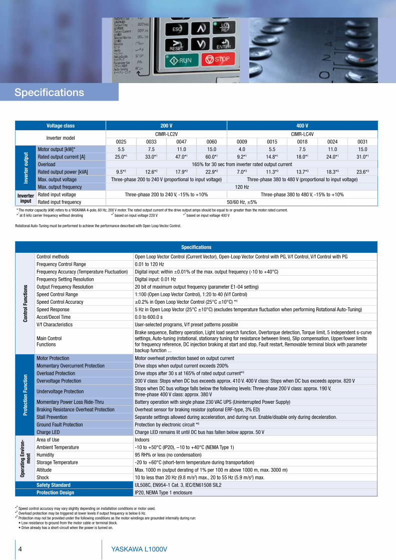
Voltage class 200 V 400 V
Inverter modelCIMR-LC2V CIMR-LC4V
0025 0033 0047 0060 0009 0015 0018 0024 0031
Inve
rter
out
put Motor output [kW]* 5.5 7.5 11.0 15.0 4.0 5.5 7.5 11.0 15.0
Rated output current [A] 25.0*1 33.0*1 47.0*1 60.0*1 9.2*1 14.8*1 18.0*1 24.0*1 31.0*1
Overload 165% for 30 sec from inverter rated output currentRated output power [kVA] 9.5*2 12.6*2 17.9*2 22.9*2 7.0*3 11.3*3 13.7*3 18.3*3 23.6*3
Max. output voltage Three-phase 200 to 240 V (proportional to input voltage) Three-phase 380 to 480 V (proportional to input voltage)Max. output frequency 120 Hz
Inverterinput
Rated input voltage Three-phase 200 to 240 V, -15% to +10% Three-phase 380 to 480 V, -15% to +10%Rated input frequency 50/60 Hz, ±5%
* The motor capacity (kW) refers to a YASKAWA 4-pole, 60 Hz, 200 V motor. The rated output current of the drive output amps should be equal to or greater than the motor rated current.
*1 at 8 kHz carrier frequency without derating *
2 based on input voltage 220 V *
3 based on input voltage 400 V
Specifications
Cont
rol F
unct
ions
Control methods Open Loop Vector Control (Current Vector), Open-Loop Vector Control with PG, V/f Control, V/f Control with PGFrequency Control Range 0.01 to 120 HzFrequency Accuracy (Temperature Fluctuation) Digital input: within ±0.01% of the max. output frequency (-10 to +40°C)Frequency Setting Resolution Digital input: 0.01 HzOutput Frequency Resolution 20 bit of maximum output frequency (parameter E1-04 setting)Speed Control Range 1:100 (Open Loop Vector Control), 1:20 to 40 (V/f Control)Speed Control Accuracy ±0.2% in Open Loop Vector Control (25°C ±10°C) *4
Speed Response 5 Hz in Open Loop Vector (25°C ±10°C) (excludes temperature fluctuation when performing Rotational Auto-Tuning)Accel/Decel Time 0.0 to 600.0 sV/f Characteristics User-selected programs, V/f preset patterns possible
Main ControlFunctions
Brake sequence, Battery operation, Light load search function, Overtorque detection, Torque limit, 5 independent s-curve settings, Auto-tuning (rotational, stationary tuning for resistance between lines), Slip compensation, Upper/lower limits for frequency reference, DC injection braking at start and stop, Fault restart, Removable terminal block with parameter backup function ...
Prot
ectio
n Fu
nctio
n
Motor Protection Motor overheat protection based on output currentMomentary Overcurrent Protection Drive stops when output current exceeds 200%Overload Protection Drive stops after 30 s at 165% of rated output current*5
Overvoltage Protection 200 V class: Stops when DC bus exceeds approx. 410 V. 400 V class: Stops when DC bus exceeds approx. 820 V
Undervoltage Protection Stops when DC bus voltage falls below the following levels: Three-phase 200 V class: approx. 190 V, three-phase 400 V class: approx. 380 V
Momentary Power Loss Ride-Thru Battery operation with single phase 230 VAC UPS (Uninterrupted Power Supply)Braking Resistance Overheat Protection Overheat sensor for braking resistor (optional ERF-type, 3% ED)Stall Prevention Separate settings allowed during acceleration, and during run. Enable/disable only during deceleration.Ground Fault Protection Protection by electronic circuit *6
Charge LED Charge LED remains lit until DC bus has fallen below approx. 50 V
Oper
atin
g En
viro
n-m
ent
Area of Use IndoorsAmbient Temperature -10 to +50°C (IP20), −10 to +40°C (NEMA Type 1)Humidity 95 RH% or less (no condensation)Storage Temperature -20 to +60°C (short-term temperature during transportation)Altitude Max. 1000 m (output derating of 1% per 100 m above 1000 m, max. 3000 m)Shock 10 to less than 20 Hz (9.8 m/s2) max., 20 to 55 Hz (5.9 m/s2) max.Safety Standard UL508C, EN954-1 Cat. 3, IEC/EN61508 SIL2Protection Design IP20, NEMA Type 1 enclosure
*4 Speed control accuracy may vary slightly depending on installation conditions or motor used.
*5 Overload protection may be triggered at lower levels if output frequency is below 6 Hz.
*6 Protection may not be provided under the following conditions as the motor windings are grounded internally during run: • Low resistance to ground from the motor cable or terminal block. • Drive already has a short-circuit when the power is turned on.
Rotational Auto-Tuning must be performed to achieve the performance described with Open Loop Vector Control.
Specifications
5
S6
S5
S4
S3
S2
S1
SC
RP
AC
R/ L1
S/ L2
T / L3
+2 +1 - B1 B2
u x
U/ T1
V / T2
W/ T3
IM
P1
PC
HC
H1
AM
AC
+
-
AMp
L1
L2
L3
PE
S7
MA
MB
MC
MD
ME
MF
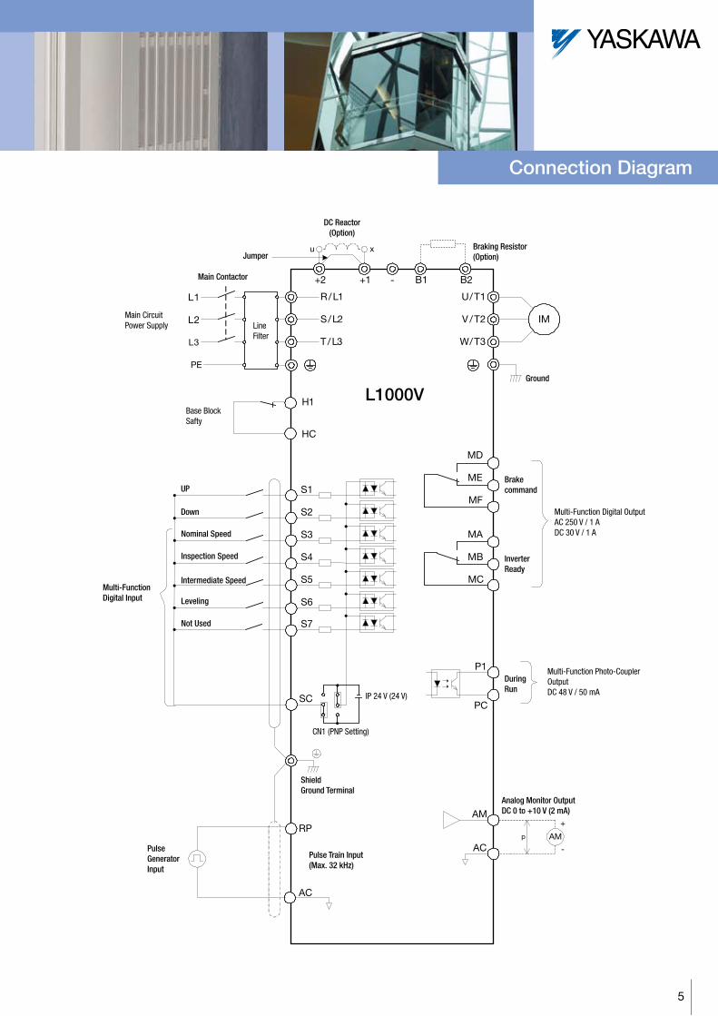
L1000v
PulseGeneratorInput
DC Reactor(Option)
Jumper
Multi-Function Digital Input
UP
Down
Nominal Speed
Inspection Speed
Intermediate Speed
Leveling
Not Used
Braking Resistor(Option)
Brakecommand
InverterReady
Multi-Function Digital OutputAC 250 V / 1 ADC 30 V / 1 A
Main CircuitPower Supply Line
Filter
Ground
Pulse Train Input(Max. 32 kHz)
Multi-Function Photo-CouplerOutputDC 48 V / 50 mA
DuringRun
Analog Monitor OutputDC 0 to +10 V (2 mA)
IP 24 V (24 V)
CN1 (PNP Setting)
Shield Ground Terminal
Main Contactor
Base BlockSafty
Connection Diagram
6 YASKAWA L1000V
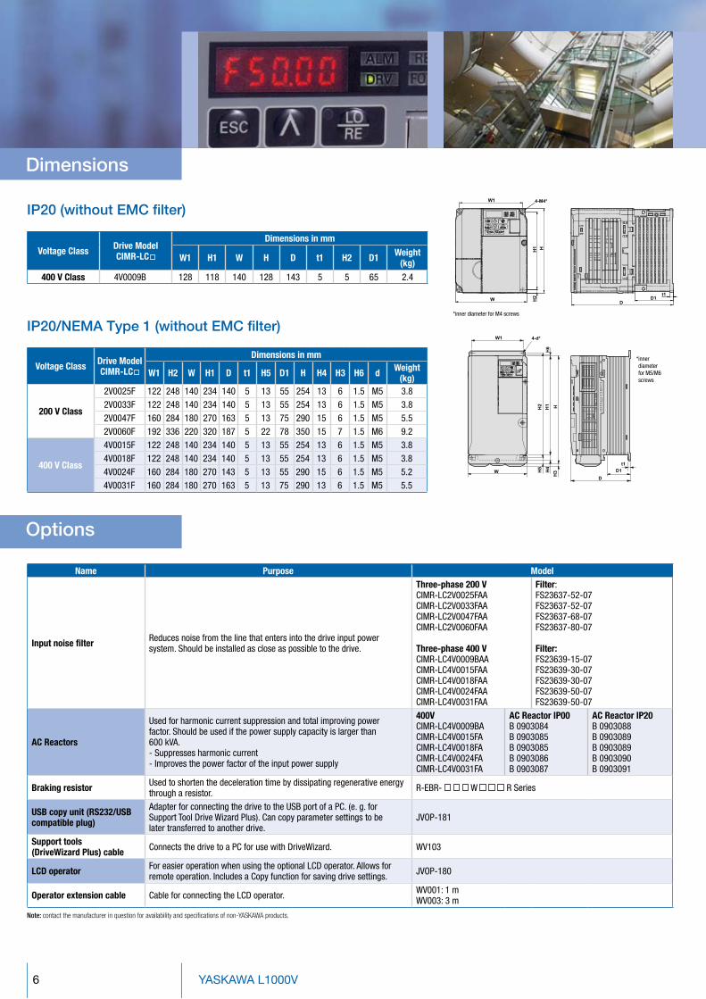
Voltage Class Drive ModelCIMR-LC
Dimensions in mm
W1 H2 W H1 D t1 H5 D1 H H4 H3 H6 d Weight (kg)
200 V Class
2V0025F 122 248 140 234 140 5 13 55 254 13 6 1.5 M5 3.82V0033F 122 248 140 234 140 5 13 55 254 13 6 1.5 M5 3.82V0047F 160 284 180 270 163 5 13 75 290 15 6 1.5 M5 5.52V0060F 192 336 220 320 187 5 22 78 350 15 7 1.5 M6 9.2
400 V Class
4V0015F 122 248 140 234 140 5 13 55 254 13 6 1.5 M5 3.84V0018F 122 248 140 234 140 5 13 55 254 13 6 1.5 M5 3.84V0024F 160 284 180 270 143 5 13 55 290 15 6 1.5 M5 5.24V0031F 160 284 180 270 163 5 13 75 290 13 6 1.5 M5 5.5
Ip20 (without EMC filter)
Voltage Class Drive ModelCIMR-LC
Dimensions in mm
W1 H1 W H D t1 H2 D1 Weight (kg)
400 V Class 4V0009B 128 118 140 128 143 5 5 65 2.4
Ip20/nEMA Type 1 (without EMC filter)* inner diameter for M4 screws
* inner diameter for M5/M6 screws
options
Name Purpose Model
Input noise filter Reduces noise from the line that enters into the drive input power system. Should be installed as close as possible to the drive.
Three-phase 200 VCIMR-LC2V0025FAACIMR-LC2V0033FAACIMR-LC2V0047FAACIMR-LC2V0060FAA
Three-phase 400 VCIMR-LC4V0009BAACIMR-LC4V0015FAACIMR-LC4V0018FAACIMR-LC4V0024FAACIMR-LC4V0031FAA
Filter:FS23637-52-07FS23637-52-07FS23637-68-07FS23637-80-07
Filter:FS23639-15-07FS23639-30-07FS23639-30-07FS23639-50-07FS23639-50-07
AC Reactors
Used for harmonic current suppression and total improving power factor. Should be used if the power supply capacity is larger than 600 kVA.- Suppresses harmonic current- Improves the power factor of the input power supply
400V CIMR-LC4V0009BACIMR-LC4V0015FACIMR-LC4V0018FACIMR-LC4V0024FACIMR-LC4V0031FA
AC Reactor IP00B 0903084B 0903085B 0903085B 0903086B 0903087
AC Reactor IP20B 0903088B 0903089B 0903089B 0903090B 0903091
Braking resistor Used to shorten the deceleration time by dissipating regenerative energy through a resistor. R-EBR- W R Series
USB copy unit (RS232/USB compatible plug)
Adapter for connecting the drive to the USB port of a PC. (e. g. for Support Tool Drive Wizard Plus). Can copy parameter settings to be later transferred to another drive.
JVOP-181
Support tools (DriveWizard Plus) cable Connects the drive to a PC for use with DriveWizard. WV103
LCD operator For easier operation when using the optional LCD operator. Allows for remote operation. Includes a Copy function for saving drive settings. JVOP-180
Operator extension cable Cable for connecting the LCD operator. WV001: 1 mWV003: 3 m
Note: contact the manufacturer in question for availability and specifications of non-YASKAWA products.
Dimensions

7
ratings & Type Descriptions
Inverter Series RevisionL1000V L 1st A
Specification Environmental SpecificationsEuropean spec. C Standard AUSA spec. U
Enclosure TypeInput Voltage Fin Filter Protection level
Three-phase 200 VAC 2 Standard No IP20 BThree-phase 400 VAC 4 Standard No NEMA 1 (IP20) F
Customer SpecificationStandard V
200 VRated output current Max. applicable motor
0025 25.0 A 5.5 kW0033 33.0 A 7.5 kW0047 47.0 A 11.0 kW0060 60.0 A 15.0 kW
400 VRated output current Max. applicable motor
0009 9.2 A 4.0 kW0015 14.8 A 5.5 kW0018 18.0 A 7.5 kW0024 24.0 A 11.0 kW0031 31.0 A 15.0 kW
CIMR- L C 2 V 0025 F A A
L1000V
YASKAWA Electric Europe GmbHHauptstr. 18565760 EschbornDeutschland / Germany
+49 6196 [email protected]
Specifications are subject to change without noticefor ongoing product modifications and improvements.© YASKAWA Electric Europe GmbH. All rights reserved.
Literature No. YEG_INV_L1000V_EN_v2_0310Printed in Germany, March 2010


![INVERTER DRIVES PRODUCT RANGE · 4 YASKAWA Inverter Drives Drive Selector 1 phase 3 phase Applicable motor Max. output [kW] Induction motor (IM) Permanent magnet motor (PM) Enclosure](https://static.documents.pub/doc/80x56/6005220642cce874457e0013/inverter-drives-product-4-yaskawa-inverter-drives-drive-selector-1-phase-3-phase.jpg)
