1 INSTALLATION, OPERATION AND MAINTENANCE MANUAL Your ventilation system should be installed in conformance with the appropriate provincial or state requirements or in the absence of such requirements with the current edition of the National Building Code, and / or ASHRAE’s “ good Engineering Practice”. IMPORTANT - PLEASE READ THIS MANUAL BEFORE INSTALLING UNIT CAUTION - Before installation, careful consideration must be given to how this system will operate if connected to any other piece of mechanical equipment, i.e. a forced air furnace or air handler, oper- ating at a higher static. After installation, the compatibility of the two pieces of equipment must be confirmed by measuring the airflow’s of the Heat / Energy Recovery Ventilators. It is always important to assess how the operation of any HRV/ERV may interact with vented combustion equipment (i.e. Gas Furnaces, Oil Furnaces, Wood Stoves, etc.). NEVER - install a ventilator in a situation where its normal opera- tion, lack of operation or partial failure may result in the backdrafting or improper functioning of vented combustion equipment!!! Light Commercial Heat/Energy Recovery Ventilator C C C US R HRV-XI 450 or ERV-XI 450 ERV-WI 500 R
Transcript
1
INSTALLATION, OPERATION AND MAINTENANCE MANUAL
Your ventilation system should be installed in conformance with the appropriate provincial or staterequirements or in the absence of such requirements with the current edition of the NationalBuilding Code, and / or ASHRAE’s “ good Engineering Practice”.
IMPORTANT - PLEASE READ THISMANUAL BEFORE INSTALLING UNIT
CAUTION - Before installation, careful consideration must be givento how this system will operate if connected to any other piece ofmechanical equipment, i.e. a forced air furnace or air handler, oper-ating at a higher static. After installation, the compatibility of the twopieces of equipment must be confirmed by measuring the airflow’s ofthe Heat / Energy Recovery Ventilators.It is always important to assess how the operation of any HRV/ERVmay interact with vented combustion equipment (i.e. Gas Furnaces,Oil Furnaces, Wood Stoves, etc.).NEVER - install a ventilator in a situation where its normal opera-tion, lack of operation or partial failure may result in the backdraftingor improper functioning of vented combustion equipment!!!
polypropylene core has a limitedlifetime warranty.
• The ERV-XI 450 energy recoveryenthalpy core has a limited 5 yearwarranty.
• The ERV-WI 500 energy recoveryenthalpy wheel has a limited 1 yearwarranty.
• The HRV-XI 450 & ERV-XI 450 has awarranty that is limited to 5 years onparts and 7 years on the motor & theERV-WI 500 has a warranty that islimited to 1 year on parts and 7 yearson the motors each from the date ofpurchase, including parts replacedduring this time period. If there is noproof of purchase available, the dateassociated with the serial number willbe used for the beginning of thewarranty period.
• The motors found in all FantechHRV/ERV’s require no lubrication,and are factory balanced to preventvibration and promote silentoperation.
• The limited warranty covers normaluse. It does not apply to any defects,malfunctions or failures as a result ofimproper installation, abuse,mishandling, misapplication,fortuitous occurrence or any othercircumstances outside Fantech’scontrol.
• Inappropriate installation or maintenance may result in thecancellation of the warranty.
• Any unauthorized work will result in the cancellation of the warranty.
• Fantech is not responsible for any incidental or consequential damagesincurred in the use of the ventilationsystem.
• Fantech is not responsible forproviding an authorized servicecentre near the purchaser or in thegeneral area.
• Fantech reserves the right to supplyrefurbished parts as replacements.
• Transportation, removal andinstallation fees are the responsibilityof the purchaser.
• The purchaser is responsible toadhering to all codes in effect in hisarea.
* This warranty is the exclusive andonly warranty in effect relative to theventilation system and all otherwarranties either expressed orimplied are invalid.
ASHRAE Standard 62-2001 defines acceptable ventilation rates forvarious applications.
Outdoor Air Requirements Examples
Application CFM per Person L/s per PersonCoin-operated laundry 15 8Cafeteria, Fast Food 20 10Bars 30 15Conference Room 20 10Reception Area 15 8Beauty Shop 25 13Classroom 15 8Libraries 15 8Medical 15 8Photo Studios 15 8Living Areas (residential) .35 air changes per hour but
not less than 15 cfm (7.5 L/s)per person
Autopsy Rooms – (0.5 cfm/Ft2 or 2.5 L/s m2)Locker Rooms – (0.5 cfm/Ft2 or 2.5 L/s m2)* Swimming Pools – (0.5 cfm/Ft2 or 2.5 L/s m2)Public Restrooms (cfm/wc or cfm/urimac) 50 25
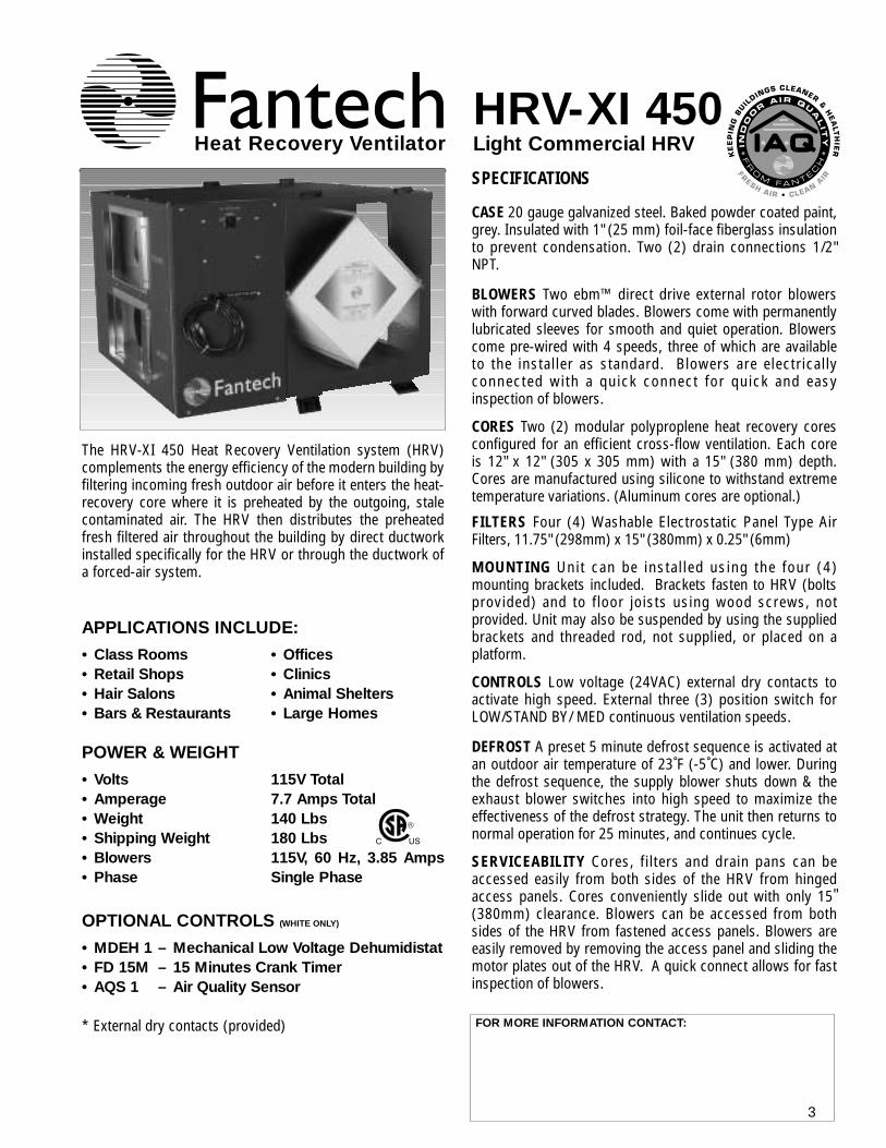
The HRV-XI 450 Heat Recovery Ventilation system (HRV)complements the energy efficiency of the modern building byfiltering incoming fresh outdoor air before it enters the heat-recovery core where it is preheated by the outgoing, stalecontaminated air. The HRV then distributes the preheatedfresh filtered air throughout the building by direct ductworkinstalled specifically for the HRV or through the ductwork ofa forced-air system.
APPLICATIONS INCLUDE:
• Class Rooms • Offices• Retail Shops • Clinics• Hair Salons • Animal Shelters• Bars & Restaurants • Large Homes
SPECIFICATIONS
CASE 20 gauge galvanized steel. Baked powder coated paint,grey. Insulated with 1" (25 mm) foil-face fiberglass insulationto prevent condensation. Two (2) drain connections 1/2"NPT.
BLOWERS Two ebm™ direct drive external rotor blowerswith forward curved blades. Blowers come with permanentlylubricated sleeves for smooth and quiet operation. Blowerscome pre-wired with 4 speeds, three of which are availableto the installer as standard. Blowers are electricallyconnected with a quick connect for quick and easyinspection of blowers.
CORES Two (2) modular polyproplene heat recovery coresconfigured for an efficient cross-flow ventilation. Each coreis 12" x 12" (305 x 305 mm) with a 15" (380 mm) depth.Cores are manufactured using silicone to withstand extremetemperature variations. (Aluminum cores are optional.)
FILTERS Four (4) Washable Electrostatic Panel Type AirFilters, 11.75" (298mm) x 15" (380mm) x 0.25" (6mm)
MOUNTING Unit can be installed using the four (4)mounting brackets included. Brackets fasten to HRV (boltsprovided) and to floor joists using wood screws, notprovided. Unit may also be suspended by using the suppliedbrackets and threaded rod, not supplied, or placed on aplatform.
CONTROLS Low voltage (24VAC) external dry contacts toactivate high speed. External three (3) position switch forLOW/STAND BY/ MED continuous ventilation speeds.
DEFROST A preset 5 minute defrost sequence is activated atan outdoor air temperature of 23˚F (-5˚C) and lower. Duringthe defrost sequence, the supply blower shuts down & theexhaust blower switches into high speed to maximize theeffectiveness of the defrost strategy. The unit then returns tonormal operation for 25 minutes, and continues cycle.
SERVICEABILITY Cores, filters and drain pans can beaccessed easily from both sides of the HRV from hingedaccess panels. Cores conveniently slide out with only 15"(380mm) clearance. Blowers can be accessed from bothsides of the HRV from fastened access panels. Blowers areeasily removed by removing the access panel and sliding themotor plates out of the HRV. A quick connect allows for fastinspection of blowers.
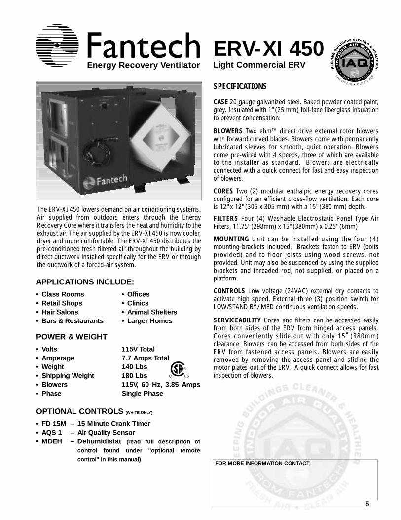
The ERV-XI 450 lowers demand on air conditioning systems.Air supplied from outdoors enters through the EnergyRecovery Core where it transfers the heat and humidity to theexhaust air. The air supplied by the ERV-XI 450 is now cooler,dryer and more comfortable. The ERV-XI 450 distributes thepre-conditioned fresh filtered air throughout the building bydirect ductwork installed specifically for the ERV or throughthe ductwork of a forced-air system.
APPLICATIONS INCLUDE:
• Class Rooms • Offices• Retail Shops • Clinics• Hair Salons • Animal Shelters• Bars & Restaurants • Larger Homes
SPECIFICATIONS
CASE 20 gauge galvanized steel. Baked powder coated paint,grey. Insulated with 1" (25 mm) foil-face fiberglass insulationto prevent condensation.
BLOWERS Two ebm™ direct drive external rotor blowerswith forward curved blades. Blowers come with permanentlylubricated sleeves for smooth, quiet operation. Blowerscome pre-wired with 4 speeds, three of which are availableto the installer as standard. Blowers are electricallyconnected with a quick connect for fast and easy inspectionof blowers.
CORES Two (2) modular enthalpic energy recovery coresconfigured for an efficient cross-flow ventilation. Each coreis 12" x 12" (305 x 305 mm) with a 15" (380 mm) depth.
FILTERS Four (4) Washable Electrostatic Panel Type AirFilters, 11.75" (298mm) x 15" (380mm) x 0.25" (6mm)
MOUNTING Unit can be installed using the four (4)mounting brackets included. Brackets fasten to ERV (boltsprovided) and to floor joists using wood screws, notprovided. Unit may also be suspended by using the suppliedbrackets and threaded rod, not supplied, or placed on aplatform.
CONTROLS Low voltage (24VAC) external dry contacts toactivate high speed. External three (3) position switch forLOW/STAND BY/ MED continuous ventilation speeds.
SERVICEABILITY Cores and filters can be accessed easilyfrom both sides of the ERV from hinged access panels.Cores conveniently slide out with only 15" (380mm)clearance. Blowers can be accessed from both sides of theERV from fastened access panels. Blowers are easilyremoved by removing the access panel and sliding themotor plates out of the ERV. A quick connect allows for fastinspection of blowers.CC US
R
OPTIONAL CONTROLS (WHITE ONLY)
• FD 15M – 15 Minute Crank Timer• AQS 1 – Air Quality Sensor• MDEH – Dehumidistat (read full description of
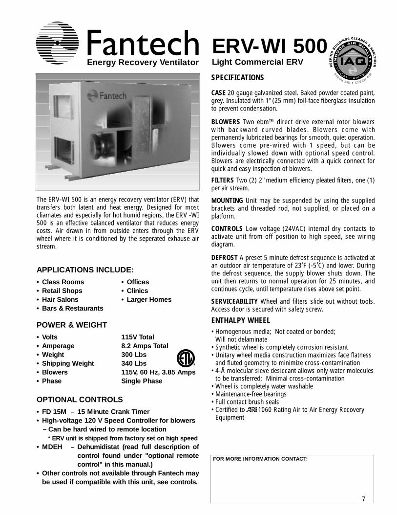
The ERV-WI 500 is an energy recovery ventilator (ERV) thattransfers both latent and heat energy. Designed for mostcliamates and especially for hot humid regions, the ERV -WI500 is an effective balanced ventilator that reduces energycosts. Air drawn in from outside enters through the ERVwheel where it is conditioned by the seperated exhause airstream.
CASE 20 gauge galvanized steel. Baked powder coated paint,grey. Insulated with 1" (25 mm) foil-face fiberglass insulationto prevent condensation.
BLOWERS Two ebm™ direct drive external rotor blowerswith backward curved blades. Blowers come withpermanently lubricated bearings for smooth, quiet operation.Blowers come pre-wired with 1 speed, but can beindividually slowed down with optional speed control.Blowers are electrically connected with a quick connect forquick and easy inspection of blowers.
FILTERS Two (2) 2" medium efficiency pleated filters, one (1)per air stream.
MOUNTING Unit may be suspended by using the suppliedbrackets and threaded rod, not supplied, or placed on aplatform.
CONTROLS Low voltage (24VAC) internal dry contacts toactivate unit from off position to high speed, see wiringdiagram.
DEFROST A preset 5 minute defrost sequence is activated atan outdoor air temperature of 23˚F (-5˚C) and lower. Duringthe defrost sequence, the supply blower shuts down. Theunit then returns to normal operation for 25 minutes, andcontinues cycle, until temperature rises above set point.
SERVICEABILITY Wheel and filters slide out without tools.Access door is secured with safety screw.
ENTHALPY WHEEL• Homogenous media; Not coated or bonded;
Will not delaminate• Synthetic wheel is completely corrosion resistant• Unitary wheel media construction maximizes face flatness
and fluted geometry to minimize cross-contamination• 4-Å molecular sieve desiccant allows only water molecules
to be transferred; Minimal cross-contamination• Wheel is completely water washable• Maintenance-free bearings• Full contact brush seals• Certified to 1060 Rating Air to Air Energy Recovery
Equipment
R
OPTIONAL CONTROLS
• FD 15M – 15 Minute Crank Timer• High-voltage 120 V Speed Controller for blowers
– Can be hard wired to remote location* ERV unit is shipped from factory set on high speed
• MDEH – Dehumidistat (read full description ofcontrol found under "optional remotecontrol" in this manual.)
• Other controls not available through Fantech maybe used if compatible with this unit, see controls.
Energy Recovery Ventilator
FOR MORE INFORMATION CONTACT:
8
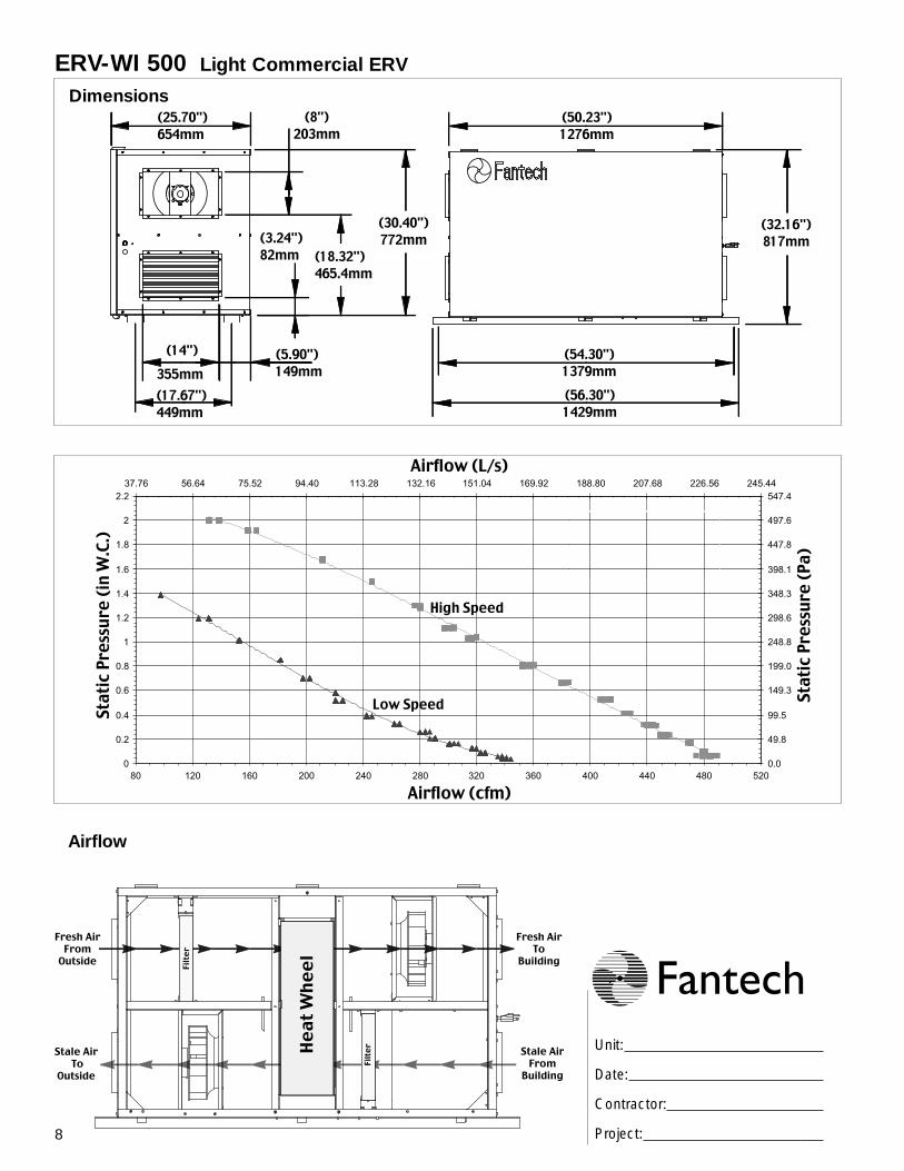
ERV-WI 500 Light Commercial ERV
Dimensions(25.70")654mm
(14")355mm
(8")203mm
(17.67")449mm
(5.90")149mm
(54.30")1379mm(56.30")1429mm
(50.23")1276mm
(32.16")817mm
(30.40")772mm
(18.32")465.4mm
(3.24")82mm
High Speed
Low Speed
Airflow (L/s)
Airflow (cfm)St
atic
Pre
ssur
e (P
a)
Stat
ic P
ress
ure
(in W
.C.)
Airflow
Unit:
Date:
Contractor:
Project:
9
Air Quality Sensor – AQS 1(Not compatible with ERV-WI 500)
The wall mount Air Quality Sensor (AQS) monitorsindoor air quality and activates the override mode whencigarette smoke, formaldehyde, benzene, volatileorganic compounds and other pollutants are detected.The unit will then return to normal mode once the airpollutants are reduced to a pre-determined lower level. Three low voltage wires are required for operation* This control is not a warning device.
Dehumidistat – MDEH 1The wall mount dehumidistat monitors the humidity levelin the area it is installed. When the humidity level risesabove the desired set-point, the HRV will activate to highspeed/override mode. Once the humidity level returns todesired condition, the unit will return to the normal mode.Two (2) low voltage wires required for operation. Note thedehumidistat helps dehumidify by increasing the speed of theHRV/ERV. Dehumidification will only take place when the air outside isdryer than the air inside.
OPTIONAL REMOTE CONTROLS
1. Continuous / Ventilation Mode In this mode of operation both fans are operating and exchanging air with the outside. The heat/energy recovery ven-tilator (HRV/ERV) constantly exchanges the air at the rate you select, either at low or medium speed, and switches tohigh speed when activated by an optional remote control. The "Low" and "Med" fan speed selection will cause the unitto operate in continuous exchange mode at a reduce exchange rate. Continuous mode is recommended, since pollu-tants are slowly but constantly being generated in a building. NOTE: Model ERV-WI 500 is a single speed unit only. Optional speed control is available.
2. Intermittent / Standby ModeThe system is always on standby and operates at high speed when activated by an optional remote control(required): "Standby" should be selected if the user wishes to stop the unit from continuous exchange.
3. Defrost (Fan shutdown HRV-XI 450 & ERV-WI 500 only)The automatic defrost cycle of HRV’s consists of a fan shut-down. When the supply air stream temperature goes below23°F (-5°C), the supply motor shuts down and the exhaustmotor goes in to high speed. Ambient air is passed throughthe unit for a period of 5 minutes. The supply motor will thenre-start and run at the preset speed. The exhaust motor willalso slow down to the preset speed, and the unit will operatein the run cycle for 25 minutes. This fan shutdown defrostcycle continues until the supply air stream rises above 23°F(-5°C).
MODES OF OPERATION
OPERATION
The HRV/ERV is shipped from the factory on low speed, intermittent operation can be obtain by toggle switch locatedon outside of cabinet (HRV-XI 450 & ERV-XI 450) or by manipulating jumpers in the electrical box. See wiring diagram.The ERV-WI 500 is factory set to high speed. Internal low voltage contacts allow interuption of power to unit whenoptional remote control is used. See spec sheet for control options.
SETTING SPEED
HRV-XI 450ERV-XI 450
Example
Dry Contacts
* HRV-XI 450 Shown
*
10
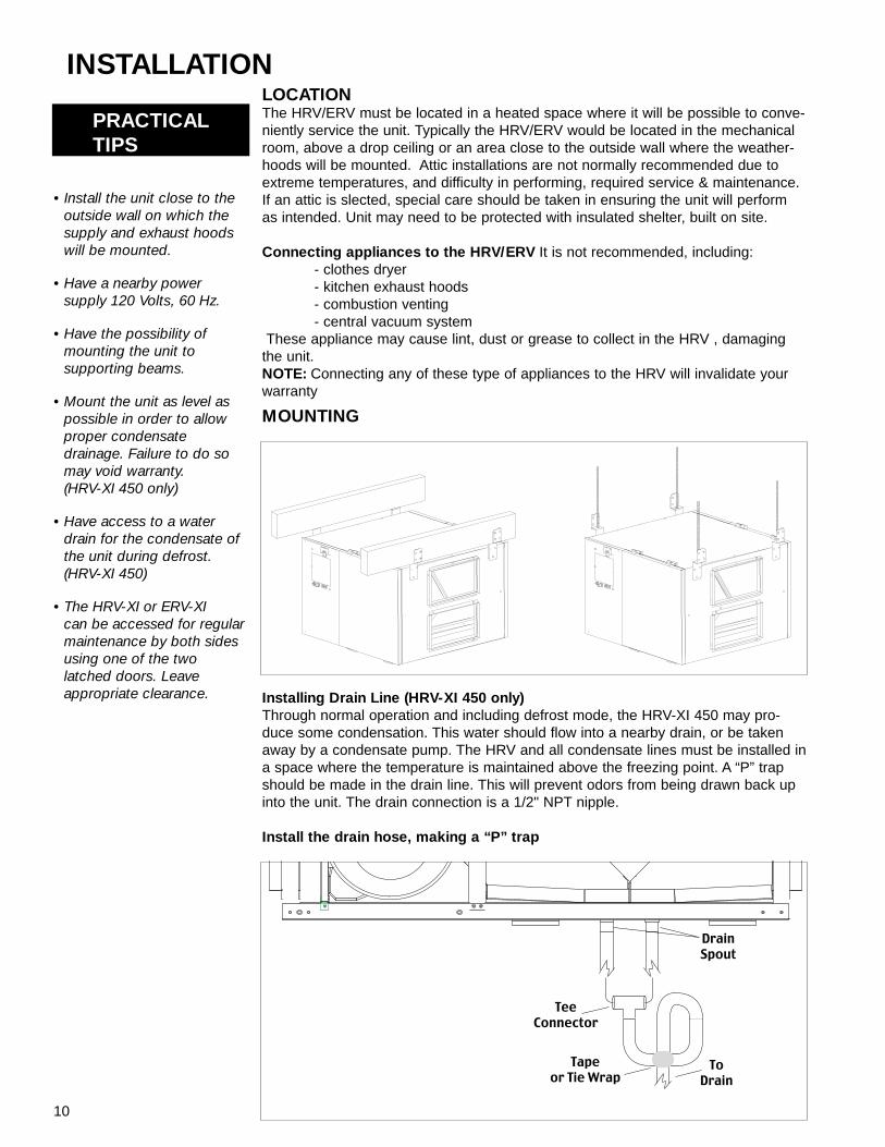
• Install the unit close to theoutside wall on which thesupply and exhaust hoodswill be mounted.
• Have a nearby powersupply 120 Volts, 60 Hz.
• Have the possibility ofmounting the unit tosupporting beams.
• Mount the unit as level aspossible in order to allowproper condensatedrainage. Failure to do somay void warranty. (HRV-XI 450 only)
• Have access to a waterdrain for the condensate ofthe unit during defrost.(HRV-XI 450)
• The HRV-XI or ERV-XI can be accessed for regularmaintenance by both sidesusing one of the twolatched doors. Leaveappropriate clearance.
INSTALLATION
PRACTICALTIPS
Installing Drain Line (HRV-XI 450 only)Through normal operation and including defrost mode, the HRV-XI 450 may pro-duce some condensation. This water should flow into a nearby drain, or be takenaway by a condensate pump. The HRV and all condensate lines must be installed ina space where the temperature is maintained above the freezing point. A “P” trapshould be made in the drain line. This will prevent odors from being drawn back upinto the unit. The drain connection is a 1/2" NPT nipple.
MOUNTING
LOCATION The HRV/ERV must be located in a heated space where it will be possible to conve-niently service the unit. Typically the HRV/ERV would be located in the mechanicalroom, above a drop ceiling or an area close to the outside wall where the weather-hoods will be mounted. Attic installations are not normally recommended due toextreme temperatures, and difficulty in performing, required service & maintenance.If an attic is slected, special care should be taken in ensuring the unit will performas intended. Unit may need to be protected with insulated shelter, built on site.
Connecting appliances to the HRV/ERV It is not recommended, including:- clothes dryer- kitchen exhaust hoods- combustion venting- central vacuum system
These appliance may cause lint, dust or grease to collect in the HRV , damagingthe unit.NOTE: Connecting any of these type of appliances to the HRV will invalidate yourwarranty
Install the drain hose, making a “P” trap
11
INSTALLING DUCTS GOING TO / FROM OUTSIDE
INSTALLING THE DUCTING TO THE WEATHERHOODS
OUTSIDE WEATHERHOODS – The weatherhoods must have built-in "bird" screens with 1/4 inch (6.35 mm)minimum mesh to prevent birds and rodents from entering into the ductwork. Do not use smaller mesh as it will be verysusceptible to pluging up. The preferred location of the weatherhoods is:
• no less than 10 ft. (3 m) apart from each other.
• at least 18 inches (457.2 mm) snow line or ground level.
• supply hood must be kept away from source of cantaminants, such as automobile exhaust fumes, gasmeters, garbage cans, containers, cooling towers, tar roofs, etc.
The outside perimeter of the weatherhood must be sealed to prevent leakage into the building.
The design and size of the weatherhoods or louvers chosen by the installer must allow for adequate free area. Waterand snow penetration of the system is minimized when the airflow does not exceed 1000 FPM (5.08 m/s) free areavelocity.
DUCTING FROM THE WEATHERHOODS–TO AND FROM THE HRV/ERV – Insulated galvanizedsheet metal ducting with sufficient cross section with an integral single piece vapor barier should be used to connectthe HRV/ERV to the weatherhoods. Insulated flex duct may be used in moderation, if sized and installed properly.(Consult local codes)
A minimum R value of insulation should be equal to 4 (RSI 0.75) ,consult local codes.
All ducts should be sealed using a good bead of high quality caulking (preferably acoustical sealant) and a high qualityaluminum foil tape, or other approved duct sealant.
12
PRACTICALTIPS
INSTALLING DUCTS TO / FROM INSIDE
• The fresh air inlet fromthe HRV needs to ensureproper air mixing andtemperature in the airhandler. Units should beinterlocked with oneanother so that the airhandler runs, when thereis a call for ventilation.
• Units may be operating atdifferent static pressures.Compatibility of the two(2) systems must be veri-fied by checking that bal-ance of the HRV/ERVfound in this manual.
Notes: See air handler manufacturer for appropriate specifications.
Direct Connection to Furnace/ Air handler return duct• Should you wish to hard duct the supply air directly into the cold air return of the
HVAC systems, remember to check the airflow balance of the HRV with the HVACsystems fan both “on”and “off” to determine that it does not imbalance the HRVmore than 10%. Make sure you respect the minimum distance from the supply airin of the HRV/ERV and the HVAC systems (Refer to your local and NationalBuilding & Heating Codes for any variations in these notes).
• It may be necessary to install a separate fresh air supply ductwork system if theheating is other than forced air.When installing an HRV/ERV, the designer and installer should be aware of localcodes that may require smoke detectors and/or firestats in the HVAC or HRV/ERVductwork.Because an HRV/ERV is designed to bring fresh air into the building, structuresmay require supply voltage interrupt when smoke or flame sensors are triggered,or when a central fire alarm system is activated.
* See installation examples found in this manual.
To maximize airflow in the ductwork system, all ducts should be kept short and have as few bends or elbows as pos-sible. Forty-five degree are preferred to 90˚ elbows. Use “Y” tees instead of 90˚ elbows whenever possible.All duct joints must be fastened with screws or duct sealant and wrapped with a quality duct tape to prevent leakage.Aluminum foil duct tape is recommended.
SUPPLY AIR DUCTINGIn buildings without a forced air HVAC systems, fresh air should be supplied to all habitable areas. It should be sup-plied from high wall or ceiling locations. Grilles that diffuse the air comfortably such as Fantech grille {MGE (metal)or PGE (plastic)}s are recommended.To avoid possible noise transfer through the ductwork system, a piece of flexi-ble ducting should be connected between the HRV and the supply ductwork system.If the floor is the only option available, then special care should be taken in locating grilles. Areas such as underbaseboard heaters will help to temper the air. Also optional inline duct heaters are available for mounting in the sup-ply duct work to add heat if required.In buildings with a forced air HVAC systems, you may want to connect the HRVto the HVAC ductwork (see information below).
13
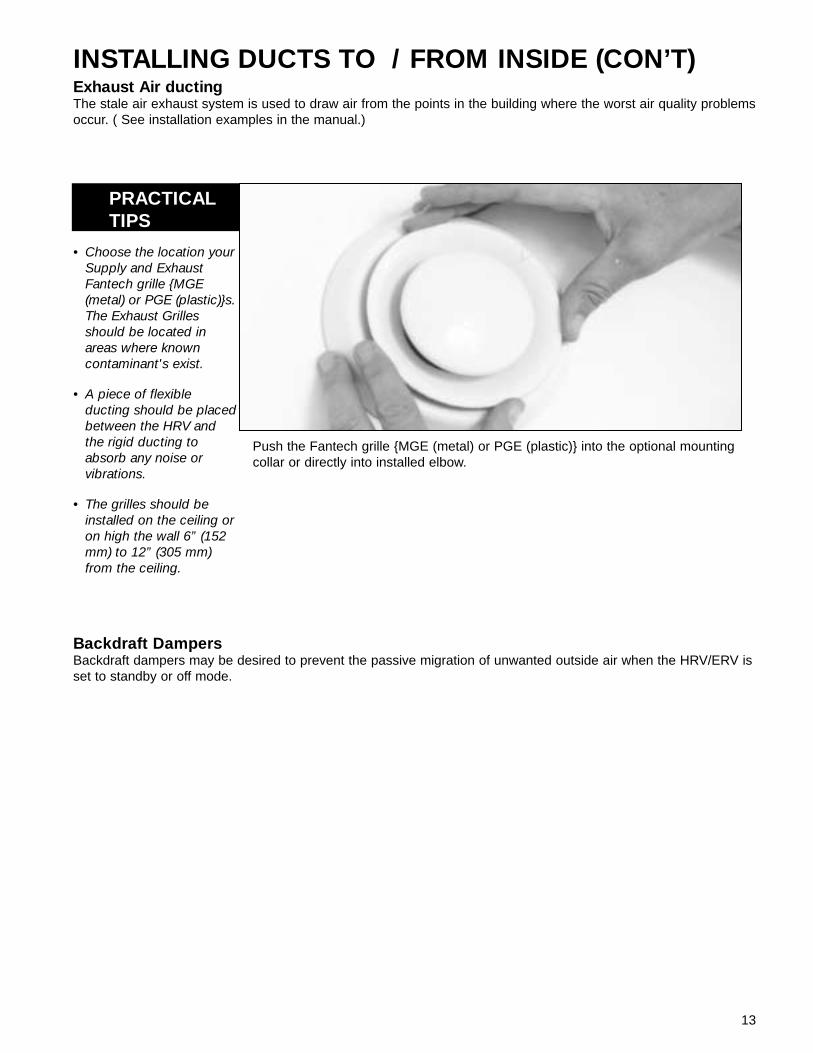
• Choose the location yourSupply and ExhaustFantech grille {MGE(metal) or PGE (plastic)}s.The Exhaust Grillesshould be located inareas where knowncontaminant's exist.
• A piece of flexibleducting should be placedbetween the HRV andthe rigid ducting toabsorb any noise orvibrations.
• The grilles should beinstalled on the ceiling oron high the wall 6” (152mm) to 12” (305 mm)from the ceiling.
Push the Fantech grille {MGE (metal) or PGE (plastic)} into the optional mountingcollar or directly into installed elbow.
INSTALLING DUCTS TO / FROM INSIDE (CON’T)
PRACTICALTIPS
Exhaust Air ductingThe stale air exhaust system is used to draw air from the points in the building where the worst air quality problemsoccur. ( See installation examples in the manual.)
Backdraft DampersBackdraft dampers may be desired to prevent the passive migration of unwanted outside air when the HRV/ERV isset to standby or off mode.
INSTALLATION EXAMPLES* Drawings are illustrations only and actual port locations and airflow directions may vary,consult unit spec sheets.It is the responsibility of the installer to ensure all ductwork is sized and installed as designed to ensure the systemwill perform as intended. The amount of air (CFM) that an HRV/ERV will deliver is directly related to the total exter-nal static pressure (E.S.P.) of the system. Static pressure is a measure of resistance imposed on the blower bylength of duct work/number of fittings used in duct work, duct heater etc.
Fully Dedicated System• Stale air drawn from areas of contamination• Fresh air supplied to main areas• HRV/ERV must be balanced• External heating or cooling coil may be needed if air is not able to mix confortably.
SUPPLY IN
EXHAUST OUT
HRV UNIT
SUPPLY DUCTRETURN AIR DUCT
EXHAUST AIR TO HRV UNIT
AIR HANDLER UNIT
SUPPLY IN
BALANCING DAMPERS
SUPPLY IN
EXHAUST OUT
HRV UNIT
SUPPLY IN
BALANCING DAMPERS
Partially Dedicated System (Direct Connection)• Stale air drawn from areas of contamination• Fresh air supplied to return of air handler• Air Handler blower may need to operate when call for ventilation• HRV/ERV must be balanced
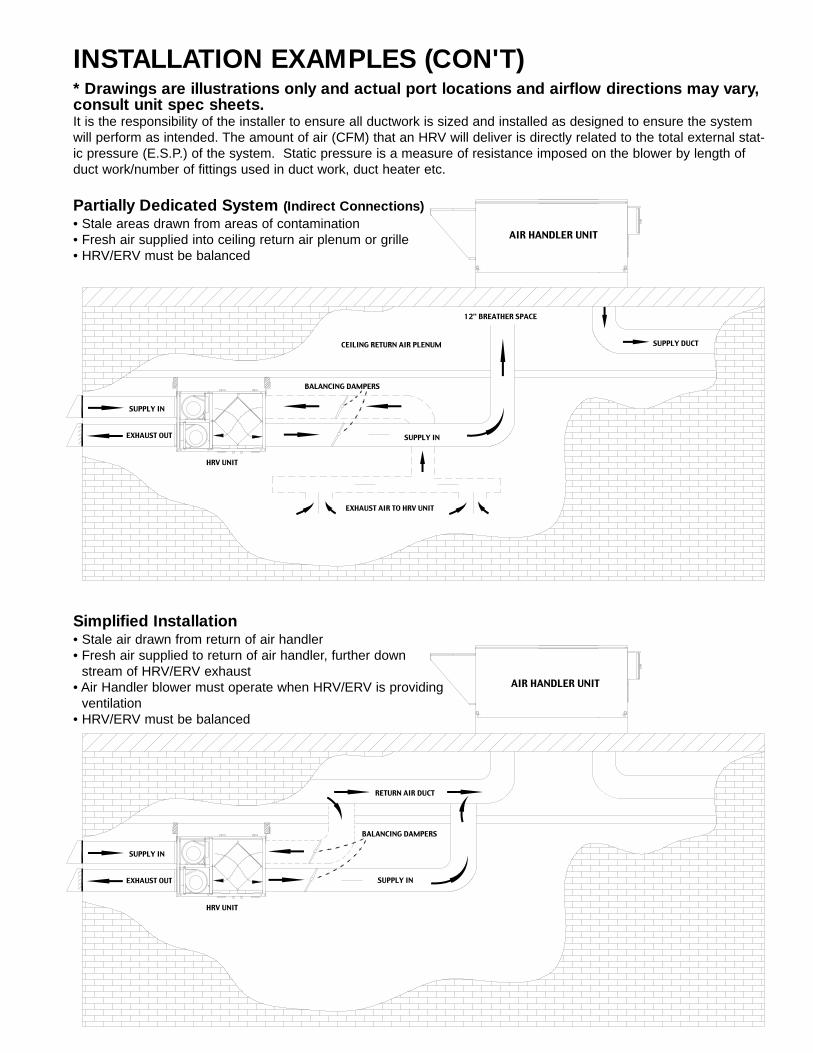
INSTALLATION EXAMPLES (CON'T)* Drawings are illustrations only and actual port locations and airflow directions may vary,consult unit spec sheets.It is the responsibility of the installer to ensure all ductwork is sized and installed as designed to ensure the systemwill perform as intended. The amount of air (CFM) that an HRV will deliver is directly related to the total external stat-ic pressure (E.S.P.) of the system. Static pressure is a measure of resistance imposed on the blower by length ofduct work/number of fittings used in duct work, duct heater etc.
SUPPLY IN
EXHAUST OUT
HRV UNIT
RETURN AIR DUCT
AIR HANDLER UNIT
SUPPLY IN
BALANCING DAMPERS
SUPPLY IN
EXHAUST OUT
HRV UNIT
SUPPLY DUCT
EXHAUST AIR TO HRV UNIT
12" BREATHER SPACE
CEILING RETURN AIR PLENUM
AIR HANDLER UNIT
SUPPLY IN
BALANCING DAMPERS
Simplified Installation• Stale air drawn from return of air handler• Fresh air supplied to return of air handler, further down
stream of HRV/ERV exhaust• Air Handler blower must operate when HRV/ERV is providing
ventilation• HRV/ERV must be balanced
Partially Dedicated System (Indirect Connections)• Stale areas drawn from areas of contamination• Fresh air supplied into ceiling return air plenum or grille• HRV/ERV must be balanced
16
PITOT TUBE BALANCING PROCEDUREPITOT TUBE
BALANCING PROCEDUREThe following is a method of field balancing an HRV/ERVusing a Pitot tube, advantageous in situations when flowstations are not installed in the ductwork. Procedureshould be performed with the HRV/ERV on high speed.
The first step is to operate all mechanical systems on highspeed, which have an influence on the ventilation system,i.e. the HRV/ERV itself and the forced air HVAC system orair handler if applicable. This will provide the maximumpressure that the HRV/ERV will need to overcome, andallow for a more accurate balance of the unit.
Drill a small hole in the duct (about 3/16"), four feet down-stream of any elbows or bends, and two feet upstream ofany elbows or bends. These are recommended distances but the actual installa-tion may limit the amount of straight duct.The Pitot tube should be connected to a magnehelic gaugeor other manometer capable of reading from 0 to 0.25 in (0-62 Pa) of water, preferably to 3 digits of resolution. Thetube coming out of the top of the pitot is connected to thehigh pressure side of the gauge. The tube coming out ofthe side of the pitot is connected to the low pressure or ref-erence side of the gauge.
Insert the Pitot tube into the duct; pointing the tip into theairflow. For general balancing it is sufficient to move thepitot tube around in the duct and take an average or typ-ical reading. Repeat this procedure in the other (supplyor return) duct. Determine which duct has the highestairflow (highest reading on the gauge). Then damperthat airflow back to match the lower reading from theother duct. The flows should now be balanced. Actualairflow can be determined from the gauge reading. Thevalue read on the gauge is called the velocity pressure.The Pitot tube comes with a chart that will give the airflow velocity based on the velocity pressure indicated bythe gauge. This velocity will be in either feet per minuteor meters per second. To determine the actual airflow,the velocity is multiplied by the cross sectional areas ofthe duct being measured.
The accuracy of the air flow reading will be affected byhow close to any elbows or bends the readings aretaken. Accuracy can be increased by taking an averageof multiple readings as outlined in the literature suppliedwith the Pitot tube.
Magnehelic
MagnehelicGauge
Duct
AirFlow
PitotTube
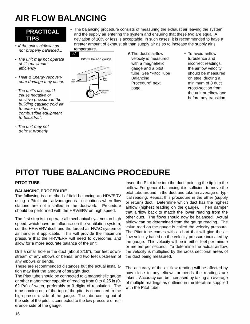
A The duct’s airflowvelocity is measuredwith a magnehelicgauge and a pitottube. See “Pitot TubeBalancingProcedure” nextpage.
• To avoid airflowturbulence andincorrect readings,the airflow velocityshould be measuredon steel ducting aminimum of 3 ductcross-section fromthe unit or elbow andbefore any transition.
• The balancing procedure consists of measuring the exhaust air leaving the systemand the supply air entering the system and ensuring that these two are equal. Adeviation of 10% or less is acceptable. In such cases, it is recommended to have agreater amount of exhaust air than supply air as so to increase the supply air’stemperature.
AIR FLOW BALANCING
PRACTICALTIPS
• If the unit’s airflows arenot properly balanced...
- The unit may not operateat it’s maximumefficiency.
- Heat & Energy recoverycore damage may occur.
- The unit’s use couldcause negative orpositive pressure in thebuilding causing cold airto enter or othercombustible equipmentto backdraft.
- The unit may not defrost properly.
A*Pitot tube and gauge
17
MAINTENANCE
The filters need to be checked and cleaned once a month or when they appear dirty.PRACTICALTIPS
• To prevent electricalshock, check that theunit is unpluggedbefore doing anyrepairs or maintenance.
• A yearly inspection isrecommended toensure the efficiencyand trouble-free use ofyour system. Runthrough the system and verify the differentoperating modes.
FILTERS
The motor - The motorsare factory balanced andlubricated for life. Theyrequire no maintenance.
The unit - The inside ofthe unit should be vacu-umed yearly. Be carefulnot to damage any of themechanical componentsand electrical connec-tions.
Condensation Panel -The condensation panelshould be cleaned yearlyor as needed.
The drain and drain line -Units with drain hosesshould have their line andconnection checked regu-larly.
Outside hoods - The out-side hoods need to bechecked every season tomake sure there are noleaves or insects blockingthe airflow. Check regu-larly that there are no pol-lutants near the intakehood. Make sure they areclear of any snow accu-mulation during the wintermonths.
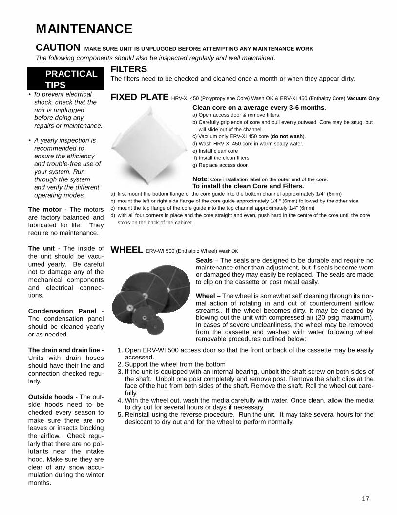
Clean core on a average every 3-6 months. a) Open access door & remove filters.b) Carefully grip ends of core and pull evenly outward. Core may be snug, but
will slide out of the channel.c) Vacuum only ERV-XI 450 core (do not wash).d) Wash HRV-XI 450 core in warm soapy water.e) Install clean coref) Install the clean filters
g) Replace access door
Note: Core installation label on the outer end of the core.To install the clean Core and Filters.
a) first mount the bottom flange of the core guide into the bottom channel approximately 1/4” (6mm)b) mount the left or right side flange of the core guide approximately 1/4 “ (6mm) followed by the other sidec) mount the top flange of the core guide into the top channel approximately 1/4” (6mm)d) with all four corners in place and the core straight and even, push hard in the centre of the core until the core
stops on the back of the cabinet.
CAUTION MAKE SURE UNIT IS UNPLUGGED BEFORE ATTEMPTING ANY MAINTENANCE WORK
The following components should also be inspected regularly and well maintained.
FIXED PLATE HRV-XI 450 (Polypropylene Core) Wash OK & ERV-XI 450 (Enthalpy Core) Vacuum Only
WHEEL ERV-WI 500 (Enthalpic Wheel) Wash OK
Seals – The seals are designed to be durable and require nomaintenance other than adjustment, but if seals become wornor damaged they may easily be replaced. The seals are madeto clip on the cassette or post metal easily.
Wheel – The wheel is somewhat self cleaning through its nor-mal action of rotating in and out of countercurrent airflowstreams.. If the wheel becomes dirty, it may be cleaned byblowing out the unit with compressed air (20 psig maximum).In cases of severe uncleanliness, the wheel may be removedfrom the cassette and washed with water following wheelremovable procedures outlined below:
1. Open ERV-WI 500 access door so that the front or back of the cassette may be easilyaccessed.
2. Support the wheel from the bottom3. If the unit is equipped with an internal bearing, unbolt the shaft screw on both sides of
the shaft. Unbolt one post completely and remove post. Remove the shaft clips at theface of the hub from both sides of the shaft. Remove the shaft. Roll the wheel out care-fully.
4. With the wheel out, wash the media carefully with water. Once clean, allow the mediato dry out for several hours or days if necessary.
5. Reinstall using the reverse procedure. Run the unit. It may take several hours for thedesiccant to dry out and for the wheel to perform normally.
18
WIRING DIAGRAM HRV-XI 450
120 VAC
4 (Black)
3 (Grey)
1 (White)
2 (Red)
5 (Blue)
NEUTRAL TB2 TB2
24VAC FOR AQS
EXHAUST6 (Green)
Blue
5 (Blue)
TB2
TB4
TB3
TB5
TB6
TB8
TB74 (Black)
2 (Red)TB9
3 (Grey)
TB101 (White)
SUPPLY
Red
Black
Black
Yellow
White
6 (Green)
CLIX-ON orTHERMISTOR
NC
TB11
GROUND
POWER CORD
120V
AC
24VA
C
FU
NC NO TB3
TB12
REMOTECONTROL
COM
TB8-TB10
(EXHAUST)R1
TB4-TB6
LIVE TB1
WhiteWhite
Red
TB4-TB6Red
TB8-TB10
NO TB7 NC NO TB3
COM
(SUPPLY)R2
COM
(DEFROST)R3
NC NO
COM
R4
TB1
DefrostTimer
121
5 4 5
3
2
4 5 4
3
1 2
3
21
5 4
3
WIRING DIAGRAM ERV-XI 450
120 VAC
TB4-TB6
4 (Black)
3 (Grey)
1 (White)
2 (Red)
5 (Blue)
NEUTRAL TB2 TB2
24VAC FOR AQS
EXHAUST6 (Green)
5 (Blue)
TB2
TB4
TB3
TB5
TB6
TB8
TB74 (Black)
2 (Red)TB9
3 (Grey)
TB101 (White)
SUPPLY
TB8-TB10
White White
Red Red
6 (Green)
TB4-TB6
(EXHAUST)
TB11
GROUND
POWER CORD
120V
AC
24VA
C
FU
NC
TB12
REMOTECONTROL
TB8-TB10
NO NCTB3 NO TB7
(SUPPLY)
COM
R1
COM
R2
1
5
212
4 5 4
3 3
LIVE TB1 TB1
19
WIRING DIAGRAM ERV-WI 500
FU
POWER CORD120 VAC
NEUTRAL
24 VAC
GROUND
LINE
211 2
Brown
(OPTIONAL)SPEED CONTROL
Blue
TB4
SUPPLYMOTOR
TB2 TB4
Blue
EXHAUST
Brown
MOTOR Black
TB7
TB8
5 4
Black
SPEED CONTROLTB10
TB9
(OPTIONAL)
5 4
WHEELMOTOR
13
9 12
14
TB5
TB1
TB6
TB3
R1 3 R2 3
5
1R3
8
4
TB5 & TB6 Internal low voltagecontacts for remote control option
Article #: 301025Rev Date: 021203
Manufactured by:
United States1712 Northgate Blvd. • Sarasota, Fl. USA 34234


![1 SAMSUNG ELECTRONICS Co. LTD. HQ SE INSTALLER ERV VER. 01- Jan. 2011 ENERGY RECOVERY VENTILATION [ERV Plus]](https://static.documents.pub/doc/80x56/56649ced5503460f949ba4c3/1-samsung-electronics-co-ltd-hq-se-installer-erv-ver-01-jan-2011-energy.jpg)


![[XLS] · Web view450. 90. 450. 900. 900. 225. 450. 450. 900. 450. 225. 270. 4.5. 450. 450. 450. 450. 450. 450. 450. 450. 450. 900. 450. 450. 450. 112.5. 900. 900. 450. 112.5. 450.](https://static.documents.pub/doc/80x56/5b3c17127f8b9a213f8d0b42/xls-web-view450-90-450-900-900-225-450-450-900-450-225-270-45.jpg)


