244 TRANSPORTATION RESEARCH RECORD 1361 Light Rail Transit Bridge Design Issues ROBERT D. NIEMIETZ AND ANTHONY W. NIEMEYER the adven! of numerous light rail projects being developed m North Amenca, the need to construct bridges to carry these systems over waterways or existing facilities has made designers aware of issues concerning these particular structures that require on items typically with railroad or highway bndges. The design of these bndges has required bridge engineers to review the applicability of existing railroad and highway bridge codes to the design of bridges that carry only the transit vehicles or specialized maintenance vehicles and that are not also to carry railroad traffic (that is, dedicated light rail bridges). These bndges also require consideration of items that are not typically associated with freight railroad or highway bridges such as power systems, aesthetic themes, stray current mitigation, and other issues. Two systems currently under construction in St. Louis, Missouri, and Dallas, Texas, have been reviewed to as- certain what light rail transit bridge issues are typically encoun- tered in design and how they may be resolved . The choice of design codes to be used as criteria for the design of light rail transit (LRT) bridges is an important decision that requires careful consideration of many factors. In the United States, the most familiar bridge design codes are the AASHTO and the American Railway Engineering Associa- tion (AREA) design specifications that apply to highway and heavy railroad bridges, respectively (1,2). Most light rail loads are significantly greater than the current HS20 truck load used by AASHTO, but not nearly as great as the Cooper E80 Loading prescribed by the current AREA code. Figure 1 depicts the bending moments produced by the Cooper E80 train, the AASHTO HS20 truck or lane load, and the transit vehicles used on the St. Louis Metro Link system and the Dallas Area Rapid Transit (DART) system. This graph shows that, for 100-ft spans, the light rail vehicles (LRVs) produce approximately 50 percent higher bending moments than the HS20 truck, but less than 20 percent of the Cooper E80 mo- ment. These relationships suggest that both the AASHTO and AREA bridge codes should be evaluated for their ap- plicability for light rail bridges that will carry only LRVs or specialized, weight-restricted maintenance vehicles and not freight railway loads. BRIDGE DESIGN CODES FOR LRT BRIDGES The AREA bridge specifications (2, Chs. 7, 8, and 15) were developed for the heavy freight rail systems of the United States, Canada, and Mexico. The service conditions, fre- quency, and types of loadings that are applicable to bridges for freight railroads are not mirrored in dedicated LRT sys- R. D. Niemietz, Sverdrup Corporation, 801N.11th Street, St. Louis, Mo. 63101. A. W. Niemeyer, Sverdrup Corporation, 3131 McKinney Avenue, Suite 600, Dallas, Tex. 75204. terns. The AREA specifications do form a basis for light rail bridge design, but sound engineering judgment should be used in the application of those specifications to LRT bridges and should modify them in certain instances. For example, the AREA steel specifications contain a statement that, for steel deck plate girders, the web-to-flange weld should be a full penetration groove weld. This is certainly applicable to an open deck (ties supported directly on the girder, Figure 2) bridge subjected to the heavy axle loads of a freight railroad that would cause significant impact and torsional loads to be applied to this weld and that haul live loads that may require th.e greater part of the bridge's load carrying capacity. For an LRT ballast deck, concrete slab on steel deck girder bridge (Figure 3), a significantly cheaper double fillet weld may be appropriately substituted for the groove weld specified. This is because of the relatively light impact and torsion loads applied to the light rail flange-to-web joint and also because of the fact that this type of bridge would use its carrying capacity mostly to carry dead load and therefore would not experience the wide level of stress range that a freight railroad bridge of a similar span would. Similarly the AREA specifications require that all steel deck spans greater than 50 ft in length have a bottom flange lateral bracing system. This is logical for the two-girder per track, open deck system typically employed for freight rail- roads for high lateral forces from dynamic train effects (nos- ing). This requirement may not be applicable for relatively light axle-loaded LRVs on well-maintained, ballast deck, con- crete slab on steel girder-type bridges. The majority of the load for these bridges will be transferred to the substructure at the span bearings via the stiff concrete deck in a manner similar to the accommodation of horizontal live loads by high- way bridges. The AASHTO specifications are much less se- vere regarding the need for a lower lateral bracing system. The need for this bracing system should be evaluated carefully before adding the expense for this system to LRT bridge costs. Similar type modifications to the AREA specifications for use on dedicated light rail systems may also be warranted for these particular items: • Impact loads, • Height of application of centrifugal force, • Continuous steel bridges, • Fatigue stress limitations for steel bridges, and • Steel transverse stiffener requirements. If a particular LRT system being designed is to only carry LRVs and system maintenance vehicles, then to be cost- effective the design should not strictly follow AREA E80 design requirements, but should be tailored for the loads that will actually be used on the system.
Transcript
244 TRANSPORTATION RESEARCH RECORD 1361
Light Rail Transit Bridge Design Issues
ROBERT D. NIEMIETZ AND ANTHONY W. NIEMEYER
~ith the adven! of numerous light rail projects being developed m North Amenca, the need to construct bridges to carry these systems over waterways or existing facilities has made designers aware of issues concerning these particular structures that require fo~us on items ~ot typically a~sociated with railroad or highway bndges. The design of these bndges has required bridge engineers to review the applicability of existing railroad and highway bridge codes to the design of bridges that carry only the transit vehicles or specialized maintenance vehicles and that are not also to carry fr~ight railroad traffic (that is, dedicated light rail bridges). These bndges also require consideration of items that are not typically associated with freight railroad or highway bridges such as power suppo~t systems, aesthetic themes, stray current mitigation, and other issues. Two systems currently under construction in St. Louis, Missouri, and Dallas, Texas, have been reviewed to ascertain what light rail transit bridge issues are typically encountered in design and how they may be resolved.
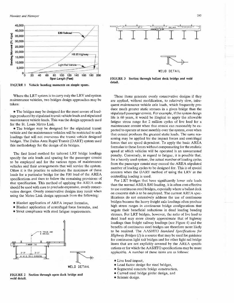
The choice of design codes to be used as criteria for the design of light rail transit (LRT) bridges is an important decision that requires careful consideration of many factors. In the United States, the most familiar bridge design codes are the AASHTO and the American Railway Engineering Association (AREA) design specifications that apply to highway and heavy railroad bridges, respectively (1,2). Most light rail loads are significantly greater than the current HS20 truck load used by AASHTO, but not nearly as great as the Cooper E80 Loading prescribed by the current AREA code. Figure 1 depicts the bending moments produced by the Cooper E80 train, the AASHTO HS20 truck or lane load, and the transit vehicles used on the St. Louis Metro Link system and the Dallas Area Rapid Transit (DART) system. This graph shows that, for 100-ft spans, the light rail vehicles (LRVs) produce approximately 50 percent higher bending moments than the HS20 truck, but less than 20 percent of the Cooper E80 moment. These relationships suggest that both the AASHTO and AREA bridge codes should be evaluated for their applicability for light rail bridges that will carry only LRVs or specialized, weight-restricted maintenance vehicles and not freight railway loads.
BRIDGE DESIGN CODES FOR LRT BRIDGES
The AREA bridge specifications (2, Chs. 7, 8, and 15) were developed for the heavy freight rail systems of the United States, Canada, and Mexico. The service conditions, frequency, and types of loadings that are applicable to bridges for freight railroads are not mirrored in dedicated LRT sys-
R. D. Niemietz, Sverdrup Corporation, 801N.11th Street, St. Louis, Mo. 63101. A. W. Niemeyer, Sverdrup Corporation, 3131 McKinney Avenue, Suite 600, Dallas, Tex. 75204.
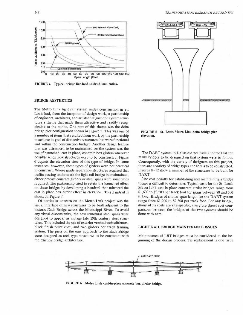
terns. The AREA specifications do form a basis for light rail bridge design, but sound engineering judgment should be used in the application of those specifications to LRT bridges and should modify them in certain instances. For example, the AREA steel specifications contain a statement that, for steel deck plate girders, the web-to-flange weld should be a full penetration groove weld. This is certainly applicable to an open deck (ties supported directly on the girder, Figure 2) bridge subjected to the heavy axle loads of a freight railroad that would cause significant impact and torsional loads to be applied to this weld and that haul live loads that may require th.e greater part of the bridge's load carrying capacity. For an LRT ballast deck, concrete slab on steel deck girder bridge (Figure 3), a significantly cheaper double fillet weld may be appropriately substituted for the groove weld specified. This is because of the relatively light impact and torsion loads applied to the light rail flange-to-web joint and also because of the fact that this type of bridge would use its carrying capacity mostly to carry dead load and therefore would not experience the wide level of stress range that a freight railroad bridge of a similar span would.
Similarly the AREA specifications require that all steel deck spans greater than 50 ft in length have a bottom flange lateral bracing system. This is logical for the two-girder per track, open deck system typically employed for freight railroads for high lateral forces from dynamic train effects (nosing). This requirement may not be applicable for relatively light axle-loaded LRVs on well-maintained, ballast deck, concrete slab on steel girder-type bridges. The majority of the load for these bridges will be transferred to the substructure at the span bearings via the stiff concrete deck in a manner similar to the accommodation of horizontal live loads by highway bridges. The AASHTO specifications are much less severe regarding the need for a lower lateral bracing system. The need for this bracing system should be evaluated carefully before adding the expense for this system to LRT bridge costs. Similar type modifications to the AREA specifications for use on dedicated light rail systems may also be warranted for these particular items:
• Impact loads, • Height of application of centrifugal force, • Continuous steel bridges, • Fatigue stress limitations for steel bridges, and • Steel transverse stiffener requirements.
If a particular LRT system being designed is to only carry LRVs and system maintenance vehicles, then to be costeffective the design should not strictly follow AREA E80 design requirements, but should be tailored for the loads that will actually be used on the system.
Where the LRT system is to carry only the LRV and system maintenance vehicles, two bridges design approaches may be taken:
• The bridges may be designed for the most severe of loadings produced by stipulated transit vehicle loads and stipulated maintenance vehicle loads. This was the design approach used for the St. Louis Metro Link.
• The bridges may be designed for the stipulated transit vehicle and the maintenance vehicles will be restricted to axle loadings that will not overstress the transit vehicle designed bridges. The Dallas Area Rapid Transit (DART) system used this methodology for the design of its bridges.
The first listed method for tailored LRT bridge loadings specify the axle loads and spacing for the passenger consist to be employed and for the various types of maintenance vehicles and their arrangements that will service the system. Often it is the practice to substitute the maximum of these loads for a particular bridge for the E80 load of the AREA specifications and then to follow the remaining provisions of that specification. This method of applying the AREA code should be used with care to preclude expensive, overly conservative designs. Overly conservative designs may result when using the Metro Link design approach from the following:
• Blanket application of AREA impact formulas, • Blanket application of centrifugal force formulas, and • Strict compliance with steel fatigue requirements.
. ~ t. TRACK AND i-' ~ BRIDGE
11 TIM88R TIE
WELD DETAIL
FIGURE 2 Section through open deck bridge and weld detail.
245
~: ·
I ~ J I ! I ,e ,.,, ' ·~·' ' f ' ·~
I I I I
WELD DETAIL
FIGURE 3 Section through ballast deck bridge and weld detail.
These items generate overly conservative designs if they are applied, without modification, to relatively slow, infrequent maintenance vehicle axle loads, which frequently produce much greater static stresses in a given bridge than the stipulated passenger consist. For example, ifthe system design life is 60 years, it would be illogical to apply the allowable fatigue stress range for 2 million cycles of live load for a maintenance consist when that consist can reasonably be expected to operate at most monthly over the system, even when that consist produces the greatest static loads. The same reasoning may be applied for the impact forces and centrifugal forces that are speed dependent. To apply the basic AREA formulas to these forces without compensating for the realistic speed at which vehicles will be operated is an unwarranted penalty. Conversely, in regard to fatigue, it is possible that, for a heavily used system, the actual number of loading cycles from the passenger consist may exceed the AREA stipulated number of loading cycles to be designed for. This is of special concern when the DART method of using the LRV as the controlling loading is used.
For LRT bridges that have significantly lower axle loads than the normal AREA E80 loading, it is often cost-effective to use continuous steel bridges, especially where a ballast deck on concrete slab is to be employed. The current AREA specifications do not extensively address the use of continuous bridges because the heavy freight axle loadings often produce high stress ranges in continuous bridge configurations that negate their beneficial reductions in dead loading bending stresses. For LRT bridges, however, the ratio of live load to dead load may more closely approximate that of highway loadings than freight railway loadings (see Figure 4) and the benefits of continuous steel bridges are therefore more likely to be realized. The AASHTO Standard Specifications for Highway Bridges (1) is a source that may be used for guidance for continuous light rail bridges and for other light rail bridge items that are not explicitly covered by the AREA specifications or for which the AASHTO specifications may be more applicable. A number of these items are as follows:
• Live load impact, • Load factor design for steel bridges, • Segmental concrete bridge construction, • Curved steel bridge girder design, and •Seismic design.
The Metro Link light rail system under construction in St. Louis had, from the inception of design work, a partnership of engineers, architects, and artists that gave the system structures a theme that made them attractive and readily recognizable to the public. One part of this theme was the delta bridge pier configuration shown in Figure 5. This was one of a number of items that resulted from work by the partnership to achieve its goal of distinctive structures that were functional and within the construction budget. Another design feature that was attempted to be maintained on the system was the use of haunched, cast in place, concrete box girders wherever possible when new structures were to be constructed. Figure 6 depicts the elevation view of this type of bridge. In some instances , however, these types of girders were not practical to construct. Where grade separation structures required that traffic passing underneath the light rail bridge be maintained, either precast concrete girders or steel spans were sometimes required. The partnership tried to retain the haunched effect on these bridges by developing a handrail that mirrored the cast in place box girder effect in elevation. This handrail is shown in Figure 7.
Of particular concern on the Metro Link project was the visual interface of new structures to be built adjacent to the historic Eads Bridge across the Mississippi River. To avoid any visual discontinuity , the new structural steel spans were designed to appear as vintage late 19th century steel structures. This included the use of exterior vertical web stiffeners, black finish paint coat , and two girders per track framing system. The piers on the east approach to the Eads Bridge were designed as arch-type structures to be consistent with the existing bridge architecture.
TRANSPORTATION RESEARCH RECORD 1361
FIGURE 5 St. Louis Metro Link delta bridge pier elevation.
The DART system in Dallas did not have a theme that the many bridges to be designed on that system were to follow. Consequently, with the variety of designers on this project , there are a variety of bridge types and forms to be constructed . Figures 8-12 show a number of the structures to be built for DART.
The cost penalty for establishing and maintaining a bridge theme is difficult to determine. Typical costs for the St. Louis Metro Link cast in place concrete girder bridges range from $1,600 to $2,200 per track foot for spans between 80 and 100 ft long. Bridges of similar span length for the DART system range from $1,200 to $2,300 per track foot. For any bridge, many of its costs are site-specific, therefore direct cost comparisons between the bridges of the two systems should be done with care .
LIGHT RAIL BRIDGE MAINTENANCE ISSUES
Maintenance of LRT bridges must be considered at the beginning of the design process. Tie replacement is one issue
~,,,,,,, ''''
- f FIGURE 6 Metro Link cast-in-place concrete box girder bridge.
Niemietz and Niemeyer
r=WALKWA Y HANDRAIL
I
FIGURE 7 Elevation showing handrail used to simulate the haunched effect called for by Metro Link's design criteria.
that requires attention and should be studied in conjunction with what types of ties are to be employed, their fastening system, available times for scheduled maintenance, and ease of making emergency, unscheduled repairs. Bridge deck designs should account for storage of replacement ties, ease of tie removal and insertion, and tamping of ties on ballast deck bridges.
Other maintenance items that should be considered in design are the use of ballast deck, open deck, or direct fixation deck bridges. These types are shown in Figures 13-15. Each has it own particular advantages and disadvantages:
Ballast deck
Advantages
Good ride quality Impact damping Good live load distribution Good track support Standard track mainte-
nance Good retainage of track
debris
Open deck Light dead load Low first cost Ease of tie replacement Low deck depth
Direct fixation Low maintenance deck Low deck depth
Relatively good ride quality
Relatively good live load distribution
Relatively low dead load
WELDED RAIL ON BRIDGES
Disadvantages
Heavy dead load Deck drainage Greater deck depth Waterproofing may
be required
Specialized track restraint required
Relatively poor ride quality
High live load impacts
Poor retainage of track debris
High first cost Tight construction
control required Susceptible to wheel
damage Specialized rail
fasteners required
The wide use of continuous welded rail (CWR) requires the consideration of its effect on LRT bridges, especially in how temperature-induced forces in the rail are transmitted to the bridge and what effect a rail break may have on the structure.
For the bridge to be influenced by temperature changes on the rail, the rail fastening system on the bridge must be able to transmit the lateral forces applied to the rail, both live and any buckling restraint forces, to the deck and through the entire superstructure system to the bridge bearings. Rail restraint longitudinal forces are also transmitted in this fashion.
For ballast deck bridges, the typical rail track fasteners are usually employed. These range from the standard cut spike and separate rail anchor system for timber ties to spring-type
TflACK TflACK
<t. <t.
I
~ DUCTBANK
THICKENED ~LL
AT CATENARY POLES
FIGURE 8 Typical section, retained fill bridge approach at catenary poles.
247
0
fasteners most often used for concrete ties. These systems transmit rail forces to the tie and then through the ballast to the bridge deck and then to the substructure. Experience has shown this to be satisfactory for bridges composed of simple spans of moderate length.
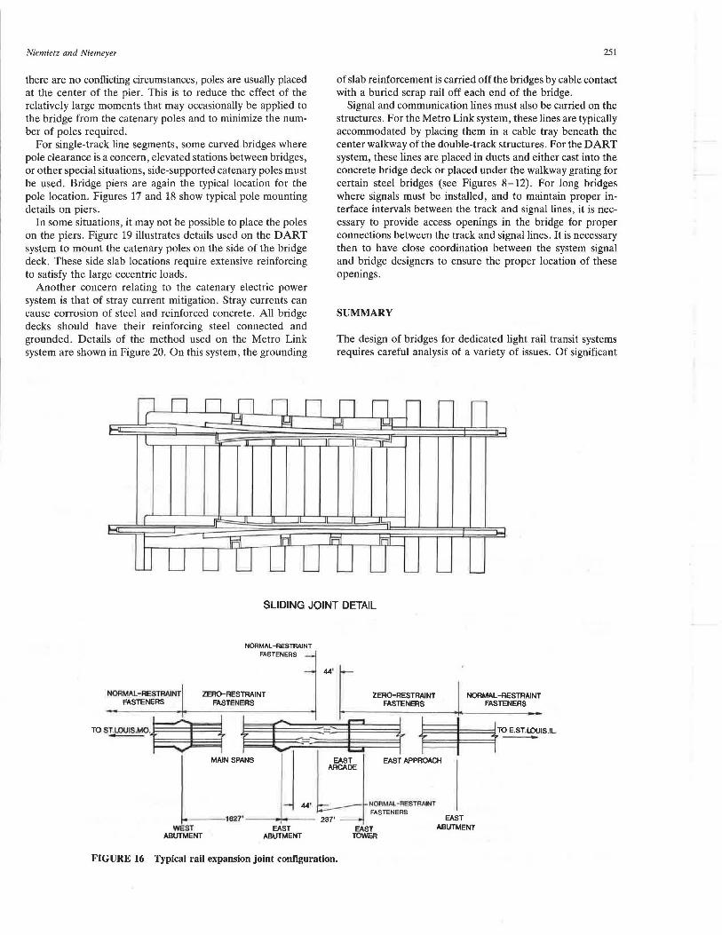
For longer bridges, where CWR is used, rail expansion joints are often used to reduce problems related to rail movements on the bridge. Figure 16 shows the typical rail expansion joint configuration. Rail expansion joints are relatively expensive and constitute an added maintenance expense.
For open deck bridges , special methods of longitudinal rail restraint are used. One major railroad had recommended that, for simple spans, the third part of the bridge adjacent to the fixed bearing end should have the rail fully boxanchored and that blocks be inserted between the ties to prevent bunching.
The use of CWR on bridges also has created concern over the forces that it may impart to the bridge. For example, a 115-lb rail, completely restrained , develops a force of 191,000 lbs when subjected to a 90°F temperature rise or fall. There is considerable concern over the effect that rail thermal forces may have on the bridge if, for example, the 191,000-lb force noted above is developed and applied to the bridge superstructure. As the rail attempts tp contract or expand, the motion of the rail transfers part of this force through the rail fasteners into the bridge deck and then into the bridge structure. Although these forces should be considered, it should
be noted that the transfer of forces applied to the rail and then to the bridge structure is a complex procedure. For example, the AREA specifications concerning the transfer of longitudinal tractive or braking forces reduces the 15 percent of applied vertical load to the rail by friction by a factor of the bridge length (in feet) divided by 1,200. This reduces longitudinal force to a negligible effect for most bridge lengths. The commentary to Chapter 15 of the AREA specifications (2) notes the reason for this reduction to be the tendency for rail forces to be transmitted off the bridge to the at-grade track structure. This shifting of the rail forces was empirically derived and is applicable only where the rails are continuous or are continually fastened together by joint bars. If rail expansion joints are used on the bridge, or the rails are otherwise not continuous, this substantial reduction in longitudinal force is not to be applied. This same reasoning may be used when considering rail thermal forces in unbroken rail.
Broken rail on LRT bridges is an issue that requires consideration because of the potential large transfer of force to the bridge and for the possibility for derailments because of rail gap formation. It is theoretically possible that, for a particular combination of rail laying temperature, rail restraint devices, span length , bridge expansion bearing configuration,
249
PIER lflACK ~ C(_
I '
I '
I I
and rail temperature at time of break, a relatively large (2 to 3 in.) gap may develop. The possibility that the rail may break under a wheel of the transit vehicle is a concern that has received much attention on several LRT systems that have been recently developed. Although this is an issue that should be considered, its importance may be mitigated by the following factors:
• Length of gap formation may not be more contributory to derailment than broken rail vertical deflection, which is not gap size dependent;
• Broken rail most often does not occur under load and will give a signal indication of a track defect to alert the transit vehicle; and
•Modern methods of rail inspection, both before and after installation, can detect rail defects or detect flaw growth before they are of a size to precipitate a crack or break. Broken rail results primarily from defects and not rail overstress.
Concern has risen over the possibility of rail gaps and the transfer of thermal-induced rail forces to the bridge structure that would theoretically result when CWR breaks at a low ambient temperature if that rail was installed at a relatively
high neutral temperature . This has caused some designers to request that, when CWR is used on a bridge, that it be laid at a lower than normal neutral temperature. The rail neutral temperature is the rail temperature that would theoretically result in zero rail thermal stress. Welded rail is typically installed at a neutral temperature that is in the upper 15 to 20 percent of the historical air temperature range of a particular locale. This is to forestall the more dangerous and prevalent susceptibility of the rail to buckle.
BALLAST
FIGURE 13 Ballast deck.
TRANSPORTATION RESEARCH RECORD 1361
PLAN
I I TIMBER TIE 12" C. TO C. I I
SECTION
FIGURE 14 Open deck.
Unless there are extraordinary circumstances or a bridge is unusually long, CWR on bridges should be installed at the neutral temperature used for the rail installation on grade. The reasons for this are as follows:
• Experience has shown that rail neutral temperature shifts downward with time (3).
• In regard to the effect on a bridge that the breaking of a rail in tension may have, it should be noted that AREA has not included this as a bridge design criterion.
• Rail buckles noted above are just as apt as broken rail to cause derailments and do not give a signal indication of this track defect as does broken rail.
•"Tight rail," which is caused by excessive rail compressive stress, is a rail maintenance problem that can cause rail corrugations, alignment defects, and rail fastener failure. Maintenance of the correct neutral temperature will reduce rail compressive stress.
POWER AND SIGNAL SYSTEM CONSIDERATIONS
Most light rail systems are powered by overhead catenary systems. On bridges, the pole support is typically placed on the bridge piers. If the bridge is a double-track structure and
STEEL BOX BEAM
FIGURE 15 Direct fixation deck.
Niemietz and Niemeyer
there are no conflicting circumstances, poles are usually placed at the center of the pier. This is to reduce the effect of the relatively large moments that may occasionally be applied to the bridge from the catenary poles and to minimize the number of poles required.
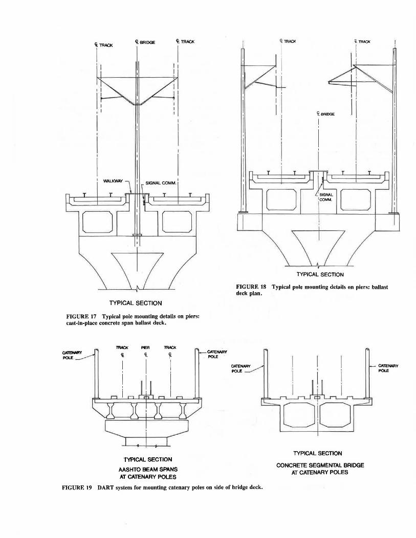
For single-track line segments, some curved bridges where pole clearance is a concern, elevated stations between bridges, or other special situations, side-supported catenary poles must be used. Bridge piers are again the typical location for the pole location. Figures 17 and 18 show typical pole mounting details on piers.
In some situations, it may not be possible to place the poles on the piers. Figure 19 illustrates details used on the DART system to mount the catenary poles on the side of the bridge deck. These side slab locations require extensive reinforcing to satisfy the large eccentric loads.
Another concern relating to the catenary electric power system is that of stray current mitigation. Stray currents can cause corrosion of steel and reinforced concrete. All bridge decks should have their reinforcing steel connected and grounded. Details of the method used on the Metro Link system are shown in Figure 20. On this system, the grounding
251
of slab reinforcement is carried off the bridges by cable contact with a buried scrap rail off each end of the bridge.
Signal and communication lines must also be carried on the structures. For the Metro Link system, these lines are typically accommodated by placing them in a cable tray beneath the center walkway of the double-track structures. For the DART system, these lines are placed in ducts and either cast into the concrete bridge deck or placed under the walkway grating for certain steel bridges (see Figures 8-12). For long bridges where signals must be installed, and to maintain proper interface intervals between the track and signal lines, it is necessary to provide access openings in the bridge for proper connections between the track and signal lines. It is necessary then to have close coordination between the system signal and bridge designers to ensure the proper location of these openings.
SUMMARY
The design of bridges for dedicated light rail transit systems requires careful analysis of a variety of issues. Of significant
FIGURE 17 Typical pole mounting details on piers: cast-in-place concrete span ballast deck.
TYPICAL SECTION
AASHTO BEAM SPANS AT CATENARY POLES
I
Cf. BRIDGE 1 1
'
I I
I I
D ~=~ o
TYPICAL SECTION
FIGURE 18 Typical pole mounting details on piers: ballast deck plan.
TYPICAL SECTION
CONCRETE SEGMENTAL BRIDGE AT CATENARY POLES
CATENAAY POU:
FIGURE 19 DART system for mounting catenary poles on side of bridge deck.
Niemietz and Niemeyer
~SYM.ABT.l BRIDGE
I
NOTE A
STEEL CONNECTING STRAP (O BOTH ENDS OF BOTH DECK SLABS! COPPER BOND !BY OTHERS!
253
NOTE A: ALL LAPS SHALL BE TACK WELDED TO MAKE REINFORCEMENT ELECTRICALLY CONTINUOUS THROUGHOUT LENGTH OF EACH DECK SECTION. AT BOTH ENOS OF EACH DECK SECTION THESE ~ BARS SHOULD BE CONNECTED TOGETHER BY A l'/2" x If•" FLAT STEEL SECTION WELDED TO THE BARS AND BROUGHT TO THE SURFACE OF THE CONCRETE.
FIGURE 20 Metro Link system for stray current grounding.
importance is the recognition that no current bridge design code exists that is completely applicable for the design of light rail bridges. Modification of current AREA and AASHTO bridge design codes is required to address the design of these bridges adequately and economically. Other design issues, such as aesthetics and the use of CWR on bridges, may be site-specific and also require consideration.
REFERENCES 1. Standard Specifications for Highway Bridges, 14th ed. American
Association of State Highway and Transportation Officials, Washington, D.C., 1989.
2. Manual for Railway Engineering. American Railway Engineering Association, Washington, D.C., 1990.
3. J. M. Sundberg. Union Pacific Railroad-Laying and Maintenance Policies for CWR. AREA Bulletin 717, Vol. 89, 1988.