118


1

2
Contents ..........................................................................................................................................................................................................................2
1 Introduction ...............................................................................................................................................................................................................61.1 Lamp families ....................................................................................................................................................................................................61.2 Standards and quality: environmental aspects ...............................................................................................................................71.3 Mains power supply voltage .................................................................................................................................................................101.4 Reliability, service life and warranty ..................................................................................................................................................111.5 Date and origin code ...............................................................................................................................................................................121.6 Developments in lamp control gear ................................................................................................................................................14
2 General aspects ....................................................................................................................................................................................................152.1 Main ballast functions ...............................................................................................................................................................................152.2 Luminaire classifications ..........................................................................................................................................................................15
2.2.1 Electrical safety (four luminaire classes) .............................................................................................................................152.2.2 Dust and moisture protection (IP classification) ..........................................................................................................162.2.3 Degree of flammability of the mounting surface ..........................................................................................................17
2.3 Electromagnetic compatibility (EMC) .............................................................................................................................................172.3.1 General .................................................................................................................................................................................................172.3.2 Influence on other electrical or electronic equipment .............................................................................................192.3.3 Regulations .........................................................................................................................................................................................212.3.4 Luminaire design .............................................................................................................................................................................23
2.4 The Energy Efficiency Index ..................................................................................................................................................................26
3 Lamps .........................................................................................................................................................................................................................273.1 Range .................................................................................................................................................................................................................273.2 Stabilisation .....................................................................................................................................................................................................293.3 Ignition and run-up ....................................................................................................................................................................................303.4 Lamp behaviour as a function of the frequency ....................................................................................................................................323.6 Effects of temperature .............................................................................................................................................................................343.7 Optimum operation ..................................................................................................................................................................................363.8 Lamp life and depreciation ....................................................................................................................................................................373.9 Influence of switching cycle ..................................................................................................................................................................383.10 Stroboscopic effect and striations ..................................................................................................................................................393.11 Dimming .......................................................................................................................................................................................................40
4 Electronic lamp control gear .........................................................................................................................................................................414.1 Electronic high-frequency system ......................................................................................................................................................41
4.1.1 Block diagram (see Fig. 43) .......................................................................................................................................................414.1.2 Circuit diagram (see Fig. 44) .....................................................................................................................................................414.1.3 Choice of frequency .....................................................................................................................................................................424.1.4 Ignition and re-ignition .................................................................................................................................................................424.1.5 Ballast types .......................................................................................................................................................................................444.1.6 Cut-off principle ..............................................................................................................................................................................444.1.7 Harmonic distortion .....................................................................................................................................................................454.1.8 Power factor ......................................................................................................................................................................................474.1.9 Inrush current ...................................................................................................................................................................................484.1.10 Circuit breakers and fusing .....................................................................................................................................................494.1.11 Earth leakage ..................................................................................................................................................................................50
Contents

3
4.1.12 Electrical connections ................................................................................................................................................................504.1.13 Internal and external cabling .................................................................................................................................................504.1.14 Lifetime ..............................................................................................................................................................................................514.1.15 Effects of mains voltage fluctuations .................................................................................................................................534.1.16 Ambient and operating temperatures .............................................................................................................................544.1.17 Earthing .............................................................................................................................................................................................554.1.18 Fault finding .....................................................................................................................................................................................564.1.19 Installation aspects .......................................................................................................................................................................60
4.2 Light regulation with HF ballasts ........................................................................................................................................................644.2.1 General: block and circuit diagrams .....................................................................................................................................644.2.2 The dimming process ....................................................................................................................................................................654.2.3 Ignition and re-ignition .................................................................................................................................................................654.2.4 Ballast types .......................................................................................................................................................................................654.2.5 Harmonic distortion .....................................................................................................................................................................654.2.6 Power factor ......................................................................................................................................................................................664.2.7 Electromagnetic compatibility (EMC) .................................................................................................................................664.2.8 Starting and operating temperature ....................................................................................................................................664.2.9 Input voltage versus light output with analogue ballasts ..........................................................................................674.2.10 The digital DALI (Digital Addressable Lighting Interface) ballast .......................................................................684.2.11 The Touch and Dim Ballast .....................................................................................................................................................724.2.12 Installation aspects .......................................................................................................................................................................73
4.3 Control possibilities ...................................................................................................................................................................................734.3.1 Luminaire-based controllers .....................................................................................................................................................744.3.2 Room-based solutions .................................................................................................................................................................764.3.3 Lighting Management Systems (for complete buildings) ..........................................................................................774.3.4 General-purpose products .......................................................................................................................................................784.3.6 Installation aspects ..........................................................................................................................................................................78
4.4 Electronic ballasts for DC supply voltages ....................................................................................................................................784.4.1 Introduction ......................................................................................................................................................................................784.4.2 Special lamps .....................................................................................................................................................................................784.4.3 Emergency lighting: definitions and standards ................................................................................................................794.4.4 Emergency lighting systems ......................................................................................................................................................804.4.5 The standard and regulating HF ballast with standard lamps ................................................................................82
5 Electromagnetic lamp control gear ...........................................................................................................................................................845.1 Ballasts ...............................................................................................................................................................................................................84
5.1.1 Main ballast functions ...................................................................................................................................................................845.1.2 Stabilisation .........................................................................................................................................................................................845.1.3 Ignition and re-ignition .................................................................................................................................................................845.1.4 Types of ballasts ................................................................................................................................................................................855.1.5 Ballast specification and marking ...........................................................................................................................................865.1.6 Maximum coil temperature tw and ΔT .............................................................................................................................865.1.7 Watt losses .........................................................................................................................................................................................87
5.2 Starters .............................................................................................................................................................................................................885.2.1 Main starter functions ..................................................................................................................................................................885.2.2 Starter types ......................................................................................................................................................................................885.2.3 Lifetime .................................................................................................................................................................................................89
5.3 Systems .............................................................................................................................................................................................................89

4
5.3.1 Components .....................................................................................................................................................................................895.3.2 Capacitors ...........................................................................................................................................................................................905.3.3 Filter coils ............................................................................................................................................................................................915.3.4 Power factor correction ............................................................................................................................................................925.3.5 Series connection of lamps .......................................................................................................................................................955.3.6 Neutral interruption and resonance ..................................................................................................................................955.3.7 Electrical diagrams ..........................................................................................................................................................................975.3.8 Mains voltage interruptions and short-circuiting ..........................................................................................................985.3.9 Harmonic distortion .....................................................................................................................................................................985.3.10 Electromagnetic interference .............................................................................................................................................1005.3.11 Lifetime ...........................................................................................................................................................................................1005.3.12 Ambient and operating temperatures ..........................................................................................................................1015.3.13 Effects of mains voltage fluctuations ..............................................................................................................................1045.3.14 Electrical wiring ..........................................................................................................................................................................1045.3.15 Hum .................................................................................................................................................................................................1055.3.16 Dimming ........................................................................................................................................................................................1065.3.17 Stroboscopic effect and striations ...................................................................................................................................1075.3.18 Circuit breakers, fusing and earth leakage ..................................................................................................................1095.3.19 Fault finding ..................................................................................................................................................................................1125.3.20 Installation aspects ....................................................................................................................................................................1155.3.21 Non-standard supply voltages ...........................................................................................................................................1155.3.22 Maintenance ................................................................................................................................................................................116

5

6
We are living in a rapidly changing world, and technological developments play an important part in this. Also in the world of lighting, new products and applications are launched all the time in order to give the best solution for the changing demands of the customers. Issues like better colour properties, lower power consumption, smaller dimensions, longer lifetime, lower costs, more flexibility, are the basis for modern lighting systems. New or improved lamp types and luminaires can be an adequate answer to the changing demands.But the heart of any lighting system still is and will continue to be the lamp and its control gear. The lamp circuits have to answer to numerous basic needs, including compliance with national and international safety standards, ease of installation, compatibility and, of course, price/performance ratio.
This Guide provides information on those aspects of lamp control gear that is needed to acquire understanding of the total lighting system. Together with the publications on the Internet and the various product data sheets it forms a set of information that will hopefully provide answers to all practical questions. Knowledge of all ins and outs enables designers, installers, OEMs and end-users to make a good choice when looking for the best possible lamp control gear.
Related Internet sites:For the home site of Philips Lighting: http://www.lighting.philips.com
1.1 Lamp familiesFollowing the main principle of operation, the family of electric light sources can be sub-divided as follows:
LAMPS
INCANDESCENT GAS-DISCHARGE SOLID STATE
CONVENTIONAL HALOGEN HIGH POWER LOW POWER
MERCURY SODIUM
LOW- HIGH- LOW- HIGH- PRESSURE PRESSURE PRESSURE PRESSURE
‘TL’5 ML SOX SON ‘TL’D HP SDW PL-L HPI CPO-TG PL-C MHN PL-T MHW PL-Q MHD PL-S CDM CDO CPO-TW
This Guide deals with control gear for the Low-Pressure Mercury lamps, as indicated in the grey area.A second guide deals with the HID (Sodium and High-pressure Mercury) circuits.
Both guides are divided into two parts:
- conventional gear, comprising electromagnetic ballasts, ignitors (starters) and capacitors
- electronic ballasts and controllers
In this Guide, some information about Control possibilities (controllers/sensors, 1-10V, DALI and Touch and Dim) is also included.
1 Introduction

7
Following the Philips nomenclature this guide deals with:ELECTROMAGNETIC
LAMP WATTAGE BALLAST STARTER ELECTRONIC
‘TL’ miniature 4-13 BTL S2, S10 HF-M
‘TL’-D 18-58 BTA S2, S10 e-Kyoto, HF-M,
S2E, S10E HF-B, HF-P, HF-R,
SiS10 HF-R DALI
36-58 HF-R T
70 S16 HF-P
‘TL’5 HE 14-35 - - HF-M, HF-P, HF-R,
HF-R DALI, HF-R T
‘TL’5 HO 24-54 - -HF-P, HF-R,
HF-R DALI, HF-R T
80 - - HF-P, HF-R,
HF-R DALI
‘TL’5 C 22-60 - - HF-M, HF-P, HF-R
HF-R DALI, HF-R T
‘TL’ E, ‘TL’ U 20-65 BTA S10, S10E -
PL-S 2 pin 5-11 BPL - -
PL-S 4 pin 5-11 BPL S2, S10 HF-M
PL-C 2 pin 8-26 BTL, BPL, BTA - -
PL-C 4pin 10-26 BTL S2, S10 -
10-13 HF-M
10-26 HF-P
18-26 HF-R, HF-R DALI
PL-L 18-36 BTA S2, S10 -
S2E, S10E
SiS10
18-24 - - HF-M, HF-P
36-55 - - HF-B, HF-P, HF-R
HF-R DALI
55 - - HF-RT
PL-T 2 pin 18-26 BPL, BTA - -
PL-T 4 pin 18-57 BPL, BTA SiS10, HF-M, HF-P, HF-R,
S2, S10, HF-R DALI, HF-R T
S2E, S10E
PL-H 60-120 - - HF-P
PLQ 2 pin 16-28
PLQ 4 pin 16-38
Explanation of the abbreviations:
BPL = Ballast PL
BTL = Ballast ‘TL’ miniature
BTA = Ballast ‘TL’(D)
HF-B = High-frequency - Basic
HF-P = High-frequency - Performer
HF-R = High-frequency - Regulator
HF-M = High-frequency - Matchbox
e-Kyoto = electronic - Kyoto
The range of ‘TL’ lamps is much wider than the types mentioned in the table, which contains only the more or less ‘standard’ types. There are many more versions (‘TL’ F/X/R/RS/MRS/A) and other lamp powers. Information on the various types and the related gear can be supplied by the local Philips Lighting organisation.Gear for the Retrofit lamps (like PL*E family) is not mentioned in the table, since with these lamps the gear is incorporated in the lamps themselves.
1.2 Standards and quality: environmental aspectsDesigners, contractors and installers are regularly confronted with a great variety of standards and recommendations in the field of lighting, and lamp control gear is by no means an exception in this respect. What makes things even more complicated is the fact that such standards and regulations often differ from country to country.To start with, international worldwide electrical standards for lighting have been laid down by the IEC (International Electrotechnical Commission). There is, for example, an IEC standard for tubular fluorescent lamps for general lighting purposes: IEC 60081.This standard specifies:- lamp electrical characteristics,- reference ballast characteristics,- lamp starting test,- lamp dimensions,- further information on ballast, ignitor and luminaire
design.
Not all types within a lamp family are standardised and for some new lamp types there are as yet no standards at all.Apart from these worldwide standards there are equivalent European standards as laid down by CENELEC for the EU countries. The home page of CENELEC can be found on: http://www.cenelec.org/

8
For fluorescent lamps and control gear relevant IEC and EN standards are:
- lamp caps and holders: IEC 60061
- ballasts for tubular fluorescent lamps (50/60Hz) EN 60920 / 60921
- starters for tubular fluorescent lamps: IEC 60155
- capacitors for discharge lamp circuits: IEC 61048 / 61049
- starting devices (other than glow starters): IEC 60926 / 60927
- AC supplied electronic ballasts for tubular fluorescent lamps: IEC 61347 / 60929
- tubular fluorescent lamps for general lighting purposes: IEC 60081
- single-capped fluorescent lamps (PL): IEC 61199/60901
- DC supplied electronic ballasts for tubular fluorescent lamps IEC 60924 / 60925
- self-ballasted lamps for general lighting services (SL): IEC 60968/60969
As control gear is often built into a luminaire, the most important IEC standard in this respect is: IEC 60598
EMC requirements (< 30 MHz) have been laid down in: EN 55015
EMC requirements (30 to 1000 MHz) have been laid down in: EN 55022A or B
The standards are often split up into a Safety and a Performance edition. The Safety edition deals with aspects for operation without danger to the user or the surrounding, while the Performance edition deals with issues as guarantee for ballast/lamp interchange ability, satisfactory starting and operation and the like.
Copies can be ordered via the IEC Internet address: http://iec.ch/
A set of IEC Standards has been edited.The set forms the “Omnibus Standard” for Lamp Control Gear.The standards are:
- IEC 61347-1 General and safety requirements
- IEC 61347-2-1 Particular requirements for starting devices (other than glow starters)
- IEC 61347-2-2 Particular requirements for d.c. or a.c. supplied electronic step-down converters for filament lamps
- IEC 61347-2-3 Particular requirements for a.c. supplied electronic ballasts for fluorescent lamps
- IEC 61347-2-4 Particular requirements for d.c. supplied electronic ballasts for general lighting
- IEC 61347-2-5 Particular requirements for d.c. supplied electronic ballasts for public transport lighting
- IEC 61347-2-6 Particular requirements for d.c. supplied electronic ballasts for aircraft lighting
- IEC 61347-2-7 Particular requirements for d.c. supplied electronic ballasts for emergency lighting
- IEC 61347-2-8 Particular requirements for ballasts for fluorescent lamps
- IEC 61347-2-9 Particular requirements for ballasts for discharge lamps (excluding fluorescent lamps)
- IEC 61347-2-10 Particular requirements for electronic invertors and convertors for high-frequency operation of cold start tubular discharge lamps (neon tubes)

9
This set of IEC Standards will replace the safety standards: IEC (60)920, (60)922, (60)924,(60)926, (60)928 and (6)1046. In general the contents of this first edition of the “omnibus” is the same as the contents of the “old” standards.For IEC the “old” standards remain valid until they are withdrawn, but they will vanish from the list of standards that can be bought.For CENELEC there will be definite dates for the validity of the “old” standards.Amendments and new items will be incorporated in the “omnibus” only from now on.Note: The performance standards are not affected.
CE is the abbreviation of ‘Conformité Européenne’. It states conformity of products to the most essential requirements of the European Community Directives and as such forms a kind of passport for goods to circulate freely throughout the countries of the European Community. It also enables Market Controlling Bodies to perform their inspection task more easily.Lighting products are covered by two European directives: the Electro Magnetic Compatibility (EMC) Directive and the Low Voltage (LV) Directive.Philips HF electronic ballasts carry the CE marking on the basis of fulfilling the following standards:EN 61547, EN 61000-3-2 and CISPR 55015 (as tested in a Philips reference luminaire). CE is mainly related to safety aspects.
ENEC is the abbreviation of ‘European Norm Electrotechnical Certification’. Over twenty Certification bodies from CENELEC member countries joined the ‘Agreement on the use of a commonly agreed mark of conformity for luminaires complying with European standards’, referred to as the LUM agreement. It means that if the ENEC marking is provided by one of the Certification bodies, this is also recognised by the other members. The marking can be obtained for luminaires for which a European Norm (EN) exists, barring luminaires for emergency lighting. In 1995 the LUM group and the LVE-AC (Low Voltage Electrical Equipment Advisory Committee) agreed that also luminaire accessories such as gear, ignitors, lampholders, electronic converters and capacitors, can also obtain the ENEC marking if they fulfil the harmonised EN standards.Philips HF electronic ballasts received the ENEC marking on the basis of standards IEC 61347 and IEC 60929, as
well as the ISO 9001 certificate. ENEC is mainly related to performance aspects.The number in the ENEC marking indicates the test house which gave the approval:
01 AENOR - Spain 12 BSI - United Kingdom
02 CEBEC - Belgium 13 SEV - Switzerland
03 IMQ - Italy 14 SEMKO - Sweden
04 IPQ - Portugal 15 DEMKO - Denmark
05 KEMA - Netherlands 16 FIMKO - Finland
06 NSAI - Ireland 17 NEMKO - Norway
07 SEE - Luxembourg 18 MEEI - Hungary
08 UTE - France 19 BEAB - Great Britain
09 ELOT - Greece 20 ASTA - Great Britain
10 VDE - Germany 21 EZU - Czech republic
11 OVE - Austria
Lighting products always have to comply with the safety, electromagnetic compatibility (EMC), performance and reliability rules as laid down in the relevant standards (e.g. EN 55015) before they can be introduced into the market. The examination required guaranteeing such compliance is carried out in Philips’ own testing laboratories under official supervision.In those cases where commercial interests or legal requirements demand additional national approval marks, these must be sought by submitting the products to the test authority concerned. Once approval has been received, the manufacturer is entitled to add the appropriate stamp of approval to the unit and offer it for sale.
For products originating in the Netherlands, the Dutch inspection institute KEMA (Keuringsdienst Electrotechnische Materialen Arnhem - Inspection Institute for Electro technical Materials in Arnhem) is the national test authority and can act as representative for testing authorities such as CSA (Canada) and UL (USA).
To ensure optimum quality of internal procedures, the internationally recognised ISO 9001 system for quality assurance has been implemented and is stringently applied in Philips factories and sales organisations. For example, for the ballast factory in Oss the ISO certification was obtained in 1991 for electronic gear and in 1992 for electromagnetic gear. It involves virtually all phases of development and production, including after-sales service to Philips customers.

10
Finally, a few words must be said on environmental considerations.Philips Lighting was one of the first to admit that it has a duty to set a good example when it comes to the proper management of our natural resources. This has led to considerable positive environmental effects throughout the complete product life cycle (production to recycling), which basically consists of four phases: the use of raw materials, the manufacturing of the product, the usage of the product and at the end of product life, the disposal or re-usage of the materials.Aspects that play a role in all this include:- Raw material mining and refining. Suppliers are
requested to provide the relevant environmental information and are expected to meet the same high environmental standards as Philips.
- Materials and energy used for production. Philips has introduced so-called Environmental Management Systems (EMS) and has committed itself to start certification of EMS in all its factories throughout the world.
- Production methods and their side effects. The development and machine construction departments have implemented eco-design procedures to ensure that environmental effects are taken into account in the creation process of new products and technologies. This also involves the reduction and possibly the elimination of eco-toxic materials in existing products and processes. From the beginning of 2006 Philips will e.g. stop using lead for soldering according to the EU RoHS directive. Philips has also reduced 25 per cent of its energy consumption in the year 2000 (compared with the 1993 level). Naturally, all this is also true for the packaging materials used.
- Treatment and processing of production rejects. A continuing programme has been started to study the feasibility of recycling and/or effective treatment of auxiliary materials and production waste (‘zero-waste’ production).
- Energy and material consumption during usage of the product. As a result of ongoing development new, innovative and ever-more efficient lamps, ballasts and luminaires are continually being introduced. We are also currently heavily engaged in developing a whole range of light-control devices that will enable users to tailor their lighting to the needs of the moment, thereby bringing even more energy savings.
- End-of-life disposal of the product. Great value is attached to the efficient disposal of spent products and the use of recycled materials where possible.
To achieve the maximum benefit from all these efforts, we must work together with all parties concerned: our suppliers, our customers, the trade, other manufacturers, and the governing authorities.
1.3 Mains power supply voltageIn the year 2003 all European EEC and EFTA countries (except the United Kingdom) have changed over to a nominal mains voltage of 230 V +/- 10%. Therefore, the standard range of control gear is nominally 230 V, 50 Hz.At this nominal voltage, the control gear will perform well within the limits set in the various standards, unless stated otherwise in the relevant data sheets. To obtain optimum efficiency for the total lighting system at the different mains voltages in use today, control gear is available for 220 - 230 - 240 V, 50 and/or 60 Hz.It is beyond the purpose of this guide to describe all the effects in the case of differences in the mains voltage and the indicated control gear voltage. Such information can be given on request.According to the IEC standards the system must under all circumstances function between 92 per cent and 106 per cent of the rated voltage.In general, if the mains voltage is too low, the consequences are:- reduced light output,- colour shifts,- ignition problems in extreme cases;
and if the mains voltage is too high:- reduced lifetime of lamps,- reduced lifetime of control gear,- colour shifts,- increased power consumption,- possible safety effects in extreme cases.
It is therefore advisable to always operate to use lamp control gear in accordance with the local mains voltage. Of course, the effects of mains-voltage fluctuations on the lamp are much higher with electromagnetic gear than with electronic (HF) gear.

11
For mains voltages or frequencies other than those specified, information can be given on request by the local Philips Lighting organisation.
1.4 Reliability, service life and warrantyPurchase decisions regarding lighting installations,- for example, with respect to investment or running costs, are mostly based on a lifetime of 10 to 15 years for the installation as a whole. In practice, however, there are well-constructed installations, which still function perfectly even after 20 to 25 years.It is a well-known fact that good maintenance improves the lifetime of an installation.The actual burning hours and the way of switching of course also have some effect, as do deviations from the nominal rated circumstances.In general, the system lifetime depends on the lifetime of the individual components, including lamps, luminaires, gear and cabling, as well as that of electrical distribution components such as switches and transformers. In fact, all these components are constructed to function well under nominal circumstances for approximately 10 years of continuous use, except lamps. Obviously, when the installation is not working continuously, the actual lifetime can be proportionately longer.When the circumstances differ from those rated as nominal, the practical lifetime of the lighting system will change as well. To what extent this is the case, depends on several aspects, such as:- what component is involved (e.g. under/overloaded
lamp, ballast, starter)- what factor is out of specification (e.g. temperature,
voltage, frequency)- for what period does the deviation last (e.g. for hours
or continuously)- the switching cycle; this too can have a certain
influence (heating up/cooling down).
There is, therefore, no general rule for predicting the lifetime, but when all the components are used within their specifications, the deviations from the average lifetime of 10 years will not be great.Possible reasons for replacing a lighting system, besides end of lifetime, can be:- catastrophe- renovation- the need for a higher performance
- change-over to newer concepts such as modern light sources or luminaires
- saving of energy costs- environmental aspects.
Details for lamp and gear life can be found in the related chapters.
Over the years, the dimensions and specifications of control gear equipment have changed considerably. Reasons can be:- new lamps- phased-out lamps- lower dimming levels required- multi-wattage gear- smaller luminaires need smaller ballasts- extra features
For replacement of obsolete control gear in existing projects there are then two possibilities:1. Service type: existing stock of the obsolete original
type2. Commercial type: a regular commercial ballast
WarrantyWarranty is a commercial issue and can vary according to country, production centre, product or even customer. Philips Lighting Business Unit Lighting Electronics Europe warrants in general that the technology and quality of electronic ballasts have evolved tremendously over the last ten years. Together with their high efficiency this makes electronic ballasts the most economic solution to drive discharge lamps. To demonstrate our confidence in the reliability of our products Philips now offers an extended guarantee. Philips was the first company to develop electronic ballasts. Right from the start Philips offered service and support wherever necessary and continues to do so. The high quality and technology standards of the Philips Lighting electronic ballasts of today will now be more explicitly reflected in a 3 and 5-year guarantee. This guarantee applies to all Philips Lighting electronic ballasts and will benefit the OEM, the installer and the end-user. Since Philips has always maintained a very high service and after sales support level this more explicit guarantee is really nothing new. Business as usual!

12
3 year The 3-year guarantee applies to any Philips Lighting electronic ballast. No registration is necessary. An invoice that shows the number of ballasts etc. (see leaflet for further details) is sufficient. The start of the guarantee period is the purchase date of the products.
5 year The 5-year guarantee applies to Philips Lighting electronic ballasts when used in registered projects, provided IEC compliant lamps are installed. The start of the guarantee period is the registered date of the commissioning of the lighting installation. Registration will take place via a specially designed registration form, which should be sent to the Philips office mentioned on the form, within two months of the installation of the project.
Although the 5-year guarantee is valid with all IEC compliant lamps, a Philips lamp and ballast combination will always give optimum performance because they have been designed around each other, within the IEC limits. A failure with such a tuned lamp and ballast combination is therefore less likely.
The registration form can be found via various Philips Lighting Electronics websites such as:http://www.dimming.philips.com
http://www.lampsandgear.com
The warranty and remedies are conditional on proper storage, installation, use and maintenance and conformance with any recommendations of Philips.The standard failure rates are for HF ballasts 1 per cent per 5000h and for the conventional types 1 percent per 6000h. Maximum
1.5 Date and origin codeIn order to be able to identify the place and date of manufacturing of Philips lighting products, these are marked with a special code. This can be very useful in the case of after-sales service. The lamps and gear are being made in a number of different factories, the most important in Europe being:
Incandescent lamps: Pila (Poland)Fluorescent lamps: Roosendaal (Holland), Chalon
sur Saone Cedex (France), Pila (Poland)
Halogen lamps: Pont-à-Mousson (France), Aachen (Germany), Dijon (France)
HID lamps, QL lamps: Turnhout (Belgium), Hamilton (UK).
Gear for lamps: Oss (Holland), Pila and Ketrzyn (Poland), Istanbul (Turkey)
Starters: Terneuzen (Holland)
The factory marks or symbols are standardised in the Philips standard ULN-D 1175, while the date markings are described in ULN-D 1745.
Marks: Terneuzen Pila
Weert Pont-à-Mousson
Turnhout LA Oss
Hamilton Chalon sur Saone
Most Philips lighting Electronics products (ballasts) carry the following date code, although there are some products that, for practical reasons, follow another system.The current way of date coding consists of a 3 digits figure where the first 2 digits represent the week number and the last digit is the last digit of the year. Between the week digits and the year digit there is a – (dash). Every ten years the week and year digits will be interchanged. (WW-Y Y-WW)
So the format used is according: Y-WW for the periods 1990 - 1999; 2010 - 2019
(and so on) WW-Y for the periods 2000 - 2009; 2020 - 2029
(and so on)

13
examples: 47-4 as being week 47, year 2004 04-7 as being week 04, year 2007 8-21 as being week 21, year 1998
Week numbers are expressed in 2 digits and comply with the Philips Standard UN-D 1120
In the past various different ways of date coding have been used. A list of different ways is given below.
. .
. .
. .
. . .. .. .. .
. .
Fig. 1 Old date code on BH ballasts. The number of dots corresponds with the
month of production: e.g. five dots means that the ballast was produced in May.
Date (de)coding on Philips lamp control gear
“TL”-HF
LA/L3 2
1. Printed on a sticker above the lamp connector. LA Produced in Oss L3 L for the month (November) and 3 for the year
(1983)
HF-P258TLD 96-09
2. Printed on a sticker near the input connector. HF-P258TLD is the type of ballast. 96-09 is the production date 1996 month 09.
HF-B258TLD 960113W
3. Printed on the PCB near the input connector. HF-B258TLD is the type of ballast. 960112W is the production date meaning: 96 = 1996 01 = month 01 (January) 13 = day 13 W = shift W
00280R/648
4. Printed on the PCB near the input connector. 00280R is a number for tracing the type of ballast
during production. 648 is the production date meaning 6 for 1996 and 48 for week 48.
HF-R 232 PLT 02970R 9749
5. Printed on a sticker near the lamp connector. This is used for the square ballasts. You have to open
the ballast to see the sticker HF-R 232 PLT is the type of ballast. 9749 is the production date 1997 week 49.
01980R 716
mains connector
6. This coding is used on slim-line TL5 products. 01980R is a number for tracing the type of ballast
during production. 716 is the production date meaning 7 for 1997 and 16
for week 16.
“TL” Electromagnetic
321104 LA8 18 5N
This code is stamped in the bottom plate on the backside with the following meaning: 321104 the last 5 digits of the 12NC of the
product LA8 stands for produced in Oss in 1998 18 week 18 5N day 5 shift N
8E
This code is stamped in the bottom plate on the topside meaning year 1998 and month E (May)

14
Lamps can have a different code. As example for TL5 lamps: Example: 01L9S2
01 : Day of the month L : Month (A = January, etc.) 9 : Year (9 = 1999, 1 = 2001, etc.) S : Hour (A = 00.00 – 01.00 hrs., etc.) 2 : Team number of production.
It should be noted that wattage and lamp colour are mentioned on the lamp cap.The lamp colour on the lamp is decisive, that is to say if a different colour is mentioned on the lamp, the marking on the lamp cap is decisive.
1.6 Developments in lamp control gearAs the control gear is part of the total lighting system, some overall trends in the world of lighting can be distinguished that will also affect the future of the control gear :
- miniaturisation: smaller luminaires require smaller ballasts and control
gear, which fit perfectly in the space available- fewer components: lamps with starter incorporated, as in the 2-pin version
of the PL- integration: the ballast is incorporated in the lamp, as is the case
with the compact fluorescent lamps (CFL), like SL and PL*E
- electronification: new lamps are developed that can only function well
with electronics, such as PL-T, QL and TL5- introduction of controls: dimming and switching, intelligent ballasts (DALI) or
luminaires- higher demands on safety/system protection: incorporated fuses and thermal-switches- higher customer demands: customer-tailored connection and mounting
possibilities (HF-Matchbox)- higher environmental demands: lead free soldering, recycling, environment-friendly
design, lower energy consumption- lower costs- reduction in maintenance costs
- more attention to system cost approach: the customer purchase is handled more and more as
an investment decision, including payback, etc.- tele-management as status information for
individual lighting points- multi-wattage ballasts (HF-Matchbox, HF-
Performer)

15
2 General aspects
2.1 Main ballast functionsThe optimum functioning of fluorescent lamps largely depends on the properties of the control gear used. As with all gas-discharge light sources, fluorescent lamps cannot function properly when they are operated directly from the mains supply voltage. Certain electrical and/or electronic devices have to be built into the lamp circuit, either in the lamp itself or externally in the form of what is called control gear. The control gear performs a number of functions:- it limits and stabilises the lamp current, a necessary
measure in view of the negative resistance characteristic of gas-discharge lamps (viz. when the lamp current increases, the lamp voltage will decrease),
- it ensures that the lamp continues to operate despite the fact that twice during each frequency cycle of the mains supply the voltage is zero,
- it provides the ignition voltage (higher than the normal operation voltage) for the initial lamp starting,
- it supplies controlled energy to heat the lamp electrodes during ignition (warm-start ballasts), and in some cases also during normal operation (regulating ballasts).
In addition to these basic functions, the control gear must fulfil a number of other, equally important requirements. It must:- ensure a sufficiently high power factor,- limit the harmonic distortion of the mains current,- if possible, present a high impedance to frequencies
used for switching purposes in automatic frequency-regulation circuits (AFRC or Actadis) in outdoor applications,
- offer adequate suppression of any electromagnetic interference (EMI) that might be produced by the lamp/ballast system and that could otherwise interfere with other electronic equipment,
- limit the short-circuit current and/or the current during running-up of the lamp, to protect the lamp electrodes from overloading,
- switch off the lamps when these cannot be ignited normally. This safety requirement is only valid for the HF ballasts,
- keep the lamp voltage, lamp current and lamp power within the specification during mains-voltage variations.
Finally, there is a third group of requirements dictated by the needs of both luminaire manufacturer and user : to
have control gear of small dimensions, long life, low losses (also with a view to controlled temperature), and a non-audible noise level.
With the electromagnetic control gear system, various separate components, including ballast, starter, capacitors and filter coils, help fulfil all these requirements together with the lamp.In the case of the electronic HF ballast, all the above-mentioned functions have been integrated into one electronic device, which might be called the ‘black box’.
2.2 Luminaire classificationsThere are basically three ways of classifying luminaires as far as their design and construction are concerned:1. According to the kind of protection offered against
electric shock, viz. electrical safety.2. According to the degree of protection provided against
the ingress of foreign bodies (e.g. dust and moisture).3. According to the degree of flammability of the
supporting surface for which the luminaire is designed.The following are summaries of the classifications detailed in IEC 60598 - Part 1.
2.2.1 Electrical safety (four luminaire classes)The electrical safety classification drawn up by the IEC embraces four luminaire classes: Class 0, I, II and III. The official definitions are too long to be reproduced in full here, but can be summarised as follows:
Class 0 - symbol (Note: Applicable to ordinary luminaires only, viz. a luminaire without special protection against dust or moisture).These are luminaires that are electrically insulated. There is no provision for earthing. The housing may be of an insulating material, which wholly or partly performs the insulating function, or it may be of metal that is insulated from current-carrying parts.Class 0 luminaires may include parts with reinforced insulation or double insulation.
Class I - symbol Luminaires in this class, apart from being electrically insulated, are also provided with an earthing point (labelled) connecting all those exposed metal parts that could conceivably become live in the presence of a fault condition.
16
Where the luminaire is provided with a flexible power lead, this must include an earth wire. Where this is not the case, the degree of electrical protection afforded by the luminaire is the same as that afforded by one of Class 0.Where a connection block is employed instead of a power lead, the metal housing must be connected to the earth terminal on the block. The provision made for earthing the luminaire must in all other respects satisfy the requirements laid down for Class I.
Class II - symbol Class II luminaires are so designed and constructed that exposed metal parts cannot become live. This can be achieved by means of either reinforced or double insulation, there being no provision for protective earthing.In the case of a luminaire provided with an earth contact as an aid to lamp starting, but where this earth is not connected to exposed metal parts, the luminaire is nevertheless regarded as being of Class II.A luminaire having double or reinforced insulation and provided with an earth connection or earth contact must be regarded as a Class I luminaire. However, where the earth wire passes through the luminaire as part of the provisions for through-wiring the installation, and is electrically insulated from the luminaire using Class II insulation, then the luminaire remains Class II.
Class III - symbol The luminaires in this class are those in which protection against electric shock relies on supply at Safety Extra-Low Voltage (SELV), and in which voltages higher than those of SELV (50 V AC r.m.s.) are not generated. An AC operating voltage of 42 volt maximum is common. A Class III luminaire should not be provided with a means for protective earthing.
The standard ballasts are developed for Class I luminaires. Information for other Classes can be obtained from the local Philips Lighting organisation.
The earthing of ballasts with metal housing depends on the class and construction of the luminaire.See also IEC 60598.
Class 1 luminaire (luminaire has safety earth connection):
1. Metal housing of ballast can be touched during lamp removal.
Metal housing must be connected to safety earth (via bottom plate or connector).
2. Metal housing of ballast (incl. ignition aid) cannot be touched during lamp removal.
Only functional earthing is required for proper ignition and EMC
Class 2 luminaire (luminaire has no safety earth connection):
3. Metal housing of ballast (incl. ignition aid) cannot be touched during lamp removal.
Only internal functional connection between ballast and ignition aid is needed for reliable ignition and EMC.
Today many luminaires are Class 1 and the metal ballast housing can be touched during lamp removal. All these ballasts must be connected to the safety earth via bottom plate or earth connector if available.
2.2.2 Dust and moisture protection (IP classification)
The IP (International Protection) system drawn up by the IEC 60529 classifies luminaires according to the degree of IEC protection afforded against the ingress of foreign bodies, dust and moisture. The term foreign bodies include such things as tools and fingers coming into contact with live parts.The designation to indicate the degrees of protection consists of the characteristic letters IP followed by two digits (three digits in France) indicating conformity with the conditions stated in two tables (here combined into one). The first of these so-called ‘characteristic digits’ is an indication of the protection against the ingress of foreign bodies and dust, while the second digit indicates the degree of sealing against the penetration of water. The third digit in the French system indicates the degree of impact resistance.

17
satisfy these requirements may bear the symbol . On the basis of these requirements, the following classification has been drawn up:
IEC luminaire classification according to flammability
Classification Symbol
Luminaires suitable for direct mounting only on
non-combustible surfaces
No symbol, but a warning
notice is required
Luminaires without built-in ballasts or
transformers suitable for direct mounting on
normally flammable surfaces
No symbol
Luminaires with built-in ballasts or transformers
suitable for direct mounting on normally
flammable surfaces
on type plate
2.3 Electromagnetic compatibility (EMC)2.3.1 GeneralThe importance of electromagnetic compatibility is increasing rapidly, resulting in a greater need to understand the behaviour and control of electromagnetic phenomena. In our modern technological society we rely
IEC classification according to the degree of dust and moisture protection
Dust protection Moisture protection
First numeral Symbol Degree of protection Second numeral Symbol Degree of protection
0 Non-protected 0 Non-protected
1 Protected against
solid objects
greater than 50 mm
1 Protected against
dripping water
2 Protected against
solid objects
greater than 12 mm
2 Protected against
dripping water when
tilted up to 150
3 Protected against
solid objects
greater than 2.5 mm
3 Protected against
spraying water
4 Protected against
solid objects
greater than 1.0 mm
4 Protected against
splashing
5 Dust-protected 5 Protected against
water jets
6 Dust-tight 6 Protected against
heavy seas
7 Protected against
effects of immersion
8 Protected against
submersion
Example: IP 65 indicates a luminaire, which is dust-tight, and water jet proof.
2.2.3 Degree of flammability of the mounting surfaceLuminaires cannot be mounted on just any convenient surface. The flammability of that surface and the temperature of the luminaire mounting plate impose certain restrictions in this respect. Naturally, if the surface is non-combustible, or if a certain distance spacer is employed, there is no problem.For the purpose of classification, the IEC defines flammable surfaces as being either normally flammable or readily flammable.Normally flammable refers to those materials having an ignition temperature of at least 200 deg C and that will not deform or weaken at this temperature.Readily flammable are those materials that cannot be classified as either normally flammable or non-combustible. Materials in this category are not suitable as mounting surfaces for luminaires. Suspended mounting is then the only solution.The permitted temperature of that part of the luminaire housing coming into contact with the mounting surface is laid down in the so-called F-requirements. Luminaires that

18
on the electromagnetic spectrum for radio communication, and it has long been a priority to protect the usable spectrum from spurious emissions.But this very same technological society is proliferating uncontrolled sources of interference that pollute this environment. A good example is data processing equipment containing high-speed processors, which if not carefully designed and built are notorious for emitting wide-band electrical noise. On the other hand, this very same data processing equipment is vulnerable to transient and surge voltages in the mains networks.The European Union has imposed mandatory regulations to protect the electromagnetic environment and to ensure that all electrical and electronic equipment works correctly. Manufacturers have a duty to provide electrical and electronic products that do not cause undue interference and that are not unduly affected by it.The term Electro-Magnetic Compatibility (EMC) can be understood as the peaceful co-existence of transmitters and receivers. In other words, the transmitted signal should only reach the receivers it is intended for, and receivers should only react to the signals coming from the transmitter that has been chosen. There should be no unwanted mutual influencing between the two taking place. The terms ‘transmitter’ and ‘receiver’ are not used here purely in a communicative sense, but also in a wider understanding of the terms. To the intended transmitters of electromagnetic energy, including radio and television, other sources of electromagnetic energy influencing the environment can be added.Such sources, which can be designated as ‘interferers’, including:- motorcar ignition systems,- fluorescent lamps and accessories,- electronic devices in the home,- switching contacts (relays),- atmospheric discharges (lightning).
Conversely, examples of electromagnetic receivers, besides radio and television, include:- electronic ballasts,- electronic step-down converters for low-voltage
halogen lamps,- lighting control equipment,- information processing equipment,- heart pacemakers,- bio-organisms.
So it appears that the present-day notion of EMC embraces far more than just radio interference.The term electromagnetic compatibility can be defined as ‘the ability of an electrical device to function satisfactorily in its electromagnetic environment, without unduly influencing this environment in which other electrical or electronic appliances may be present’. From this definition it follows that there is an active and a passive aspect to EMC. Hence, electromagnetic compatibility can be divided in two areas:- Emission (or interference) suppression. This should ensure that the unintentional emissions from electrical and electronic products are kept sufficiently low, so that legitimate use of the frequency spectrum is not disrupted.- Immunity. This should ensure that products are sufficiently immune to electrical interference as to be able to operate as intended in the presence of normal and acceptable background electromagnetic signals.
electricalor
electronicsystem
Fig. 2 The electromagnetic environment.
The electromagnetic environment has been represented in Fig. 2. It involves all the electromagnetic frequencies and can be split up into different frequency bands, each one related to specific applications (see Fig. 3). One could also express the frequency spectrum in terms of wavelength, because the product of frequency and wavelength equals the speed of light: 300 000 km/s.
104
30 3.10-4 3.10-6 3.10-7
109 10111012 1014 1015 1019 1022 frequency (kHz)
wavelength (m)
seicneuqerfwol
noissimsnartrewop(
)oiduadna
VTdnaoidar
setilletasdnaradar
sevaworcim
noitaidarRI
noitaidarelbisiv
noitaidarVU
syar-X
syarammag
syarcimsoc
Fig. 3 The Electromagnetic spectrum.

19
Any piece of electrical or electronic equipment interferes with its environment due to the laws of electromagnetism, viz. an electrical current can never be dissociated from producing electric and magnetic fields that influence the environment. In the case of the HF lamp system, not only the HF ballast, but also the whole combination of ballast, wiring, lamp and luminaire should be considered.To ensure that electrical or electronic systems will not cause unacceptable interference with the environment, regulations have been drawn up that place limits on the amount of interference that may be emitted by such systems.The requirements as laid down in the Directives on EMC (Electromagnetic Compatibility) by the EU are intended to prevent electromagnetic interference. This is related to emission and immunity of products having an intrinsic function. Luminaires are clearly products with an intrinsic function, and must therefore comply with all essential requirements of the EMC Directive. Whether individual components (ballasts for example) should also comply with the EMC requirements is still part of discussion between the relevant bodies of the CENELEC and the EU.
Relevant standards are:A: For the frequency range from 0 Hz to 9 kHz: EN 61000-3-2: limits for harmonic current emissions EN 61000-3-3: limits concerning voltage fluctuations
and flicker IEC 1547: EMC immunity requirements for equipment
for general lighting purposes,B: For frequencies above 9 kHz: EN 55015: electrical lighting and similar equipment: radiated and conducted interference from 9 kHz to
30 MHz EN 55022: information technology equipment: radiated field from 30 MHz to 1000 MHz,C: For the USA: FCC, 47 CFR Part 18: non-consumer equipment: conducted interference and radiated interference
150 kHz to 30 MHz.
These standards apply for the electromagnetic as well as for HF lamp systems. All Philips HF electronic ballasts surpass these norms for higher harmonics and are therefore suitable for use in installations where stringent norms for harmonics are set.
Next to these general norms, there are some specific norms for rooms where diagnostic or observation equipment is placed. In VDE 0107, norms are defined for such rooms. Measurements with Philips electronic ballasts showed that in the relevant frequency ranges, no interference of any consequence could be measured. Luminaires with Philips electronic ballasts have been handed over to the Lawrence Berkeley laboratory in the United States. Here, too, they could not find any influence on sensitive CAT-, EEG and ECG apparatus.As the influence of HF systems on interference is much more delicate than with the traditional copper/iron circuits, the accent will be laid on the Philips HF systems when dealing with this subject in this section.
2.3.2 Influence on other electrical or electronic equipment
IntroductionThe interference can be split up into two categories:1. Via wiring - interference conducted through the mains
lead a. mains harmonic distortion, 0 - 2 kHz b. conducted interference, RFI, 9 kHz - 30 MHz
2. Via the air - interference radiated to the environment. a. magnetic field, RFI, 9 kHz - 30 MHz b. electric field, RFI, 30 MHz - 1000 MHz c. infrared
Electromagnetic fields in the frequency range from 9 kHz up to 1000 MHz may disturb radio and television and is therefore called Radio Frequency Interference, RFI. It applies to the spectrum given in Fig. 4.
4 26 88 105 470 960
0.15 1.6 47 68 174 230
TL-HFQL
MHz
MHz
LW MW SW VHF1
FM UHF3
UHF4 & 5
Fig. 4 The radio frequency spectrum.
Via wiring Mains harmonic distortionIn the electronic circuit of the HF ballast, harmonic distortion is caused by the rectifier and the electrolytic capacitor. The harmonics of the input current are injected into the public electricity supply system - the mains. An electronic circuit combined with a mains input filter

20
included in the HF ballast ensures that the HF lamp system complies with the mains harmonic distortion regulations (EN61000-3-2).In the electromagnetic circuit, harmonic distortion is caused by the rectangular wave-shape of the lamp voltage (see Section 5.3.9).
Conducted interference Conducted interference is caused by the switching devices and the HF signals in the electronic circuit of the HF ballast. This kind of interference can be represented by three kinds of currents: symmetrical, asymmetrical and surroundings or common-mode currents, which are all together in the range of microamperes (4 µA maximum). These currents will be conducted through the mains and can disturb other equipment operating in the radio-frequency band.The interference level can be measured with the aid of an artificial mains network that simulates a typical public electricity supply system. There are limits for the terminal voltage measured at this network, caused by the interference currents in the live and neutral conductors.
Symmetrical current (Fig. 5a)This current is generated inside the electronic circuit and flows in the same direction as the normal supply current. Earthing has no influence on the current. The mains input filter of the ballast will reduce this current.
HF ballast
Is
0
Fig. 5a: Symmetrical current.
Asymmetrical current (Fig. 5b)This current can be split up into a ‘low’ and ‘high’ frequency part. The low- frequency part with the operating frequency is caused by the capacitive coupling of the lamp voltage to the housing. Both the lamp and the so-called ‘hot’ wires cause capacitive coupling, represented by C1 for the lamp and C2 for the wiring in Fig. 5b. The high-frequency part is caused by the capacitive coupling between the electronic circuit and the housing. These capacitive currents, called Ias are symmertrical.
They flow from the phase and neutral to the housing and then via the earth to the mains supply to close the current loop, and have the same direction. Owing to the presence of the mains input filter, only a small part of the asymmetrical current will be conducted through the mains lead. Furthermore, asymmetrical currents can occur due to ‘cross-talk’ between lamp wiring and mains wiring, represented by C3 in Fig. 5b.
Note: The asymmetrical current is sometimes confused with the common-mode
current.
HF ballast
Ias
0
C3
C2C1
+ + - -
Fig. 5b: Asymmetrical current.
Surroundings or common-mode current (Fig. 5c)The lamp radiates an electric field. Because of the presence of a parasitic capacitor between the lamp and its surroundings, represented by C4, a parasitic current, called Isurr will flow to the surroundings. This current returns to the circuit via the mains lead including the earth wire, and is therefore called Icommon-mode. Because this current will flow mainly through the ground wire, the input filter cannot reduce it. A part of this current contributes to the asymmetrical current in the mains lead, Ias in Fig. 5b. Isurr can be reduced considerably by means of a well-grounded shielding. At the same time, with this shielding, no currents can be induced into the mains lead or other surrounding wiring owing to the magnetic field of the lamp.If there is no earth lead, Isurr will flow back via the phase and/or neutral to close the current loop. This is only acceptable if C4 is small – as, for example, in the case of small lamp length, as with the PL*E/C.
C4
HF ballast
Isurr
Isurr
0
+ + - -
Fig. 5c: Surroundings current.

21
Radiated interferenceMagnetic fieldThis interference will mainly be produced by the lamp. The strength of the magnetic field created by the lamp current is depicted by the area A in Figs 6a and 6b. The magnetic interference can be kept small by decreasing area A or by using some additional screening, which can be a part of the luminaire. This will also prevent the magnetic field from inducing currents in the mains lead, which would increase the conducted interference. Furthermore, a low working frequency results in a low amount of radiation, which is why the working frequency has been chosen at 28 kHz or 45 kHz.The magnetic field can be measured very conveniently by means of a large loop antenna.
H
A
HF ballast0
A
H
Fig. 6a and 6b: Strength of the magnetic field in area A.
Electric fieldDue to the harmonics of the lamp voltage, the lamp will radiate an electric field. The harmonics are reduced considerably by means of an additional output filter in the circuit. Interference to the surroundings can be reduced by means of a shielding. Nevertheless, a field from the total system will still remain.
InfraredApart from the emission of visible light, the fluorescent lamp also emits a certain amount of invisible infrared radiation (IR). Above the operating frequency, this radiation is modulated with double the lamp-current frequency (56 or 90 kHz). The choice of the operating frequency will prevent disturbance with the Philips lighting control systems, which operate at a modulated frequency of 36 kHz (RC5 protocol).
2.3.3 RegulationsEurope Mains harmonic distortionThe harmonics of the input current must comply with EN 61000-3-2. The limits for class C apply (Lighting equipment having an input power > 25 W).
Harmonic input current limits
Harmonic order Maximum permissible harmonic
currrent expressed as a percentage
of the input current at the
fundamental frequency %
2 2
3 30 . power factor
5 10
7 7
9 5
11 < n < 39 (Odd harmonics only) 3
Conducted interferenceThe requirements of EN 55015 apply (see Fig. 7).
021
001
08
06
04
02100.0
10.01.0 1 01 001
U (dBµv)
f (MHz)
quasi-peak
average
Fig. 7 Limits of mains terminal interference voltage in the range from 9 kHz to 30
MHz, according to EN 55015.
22
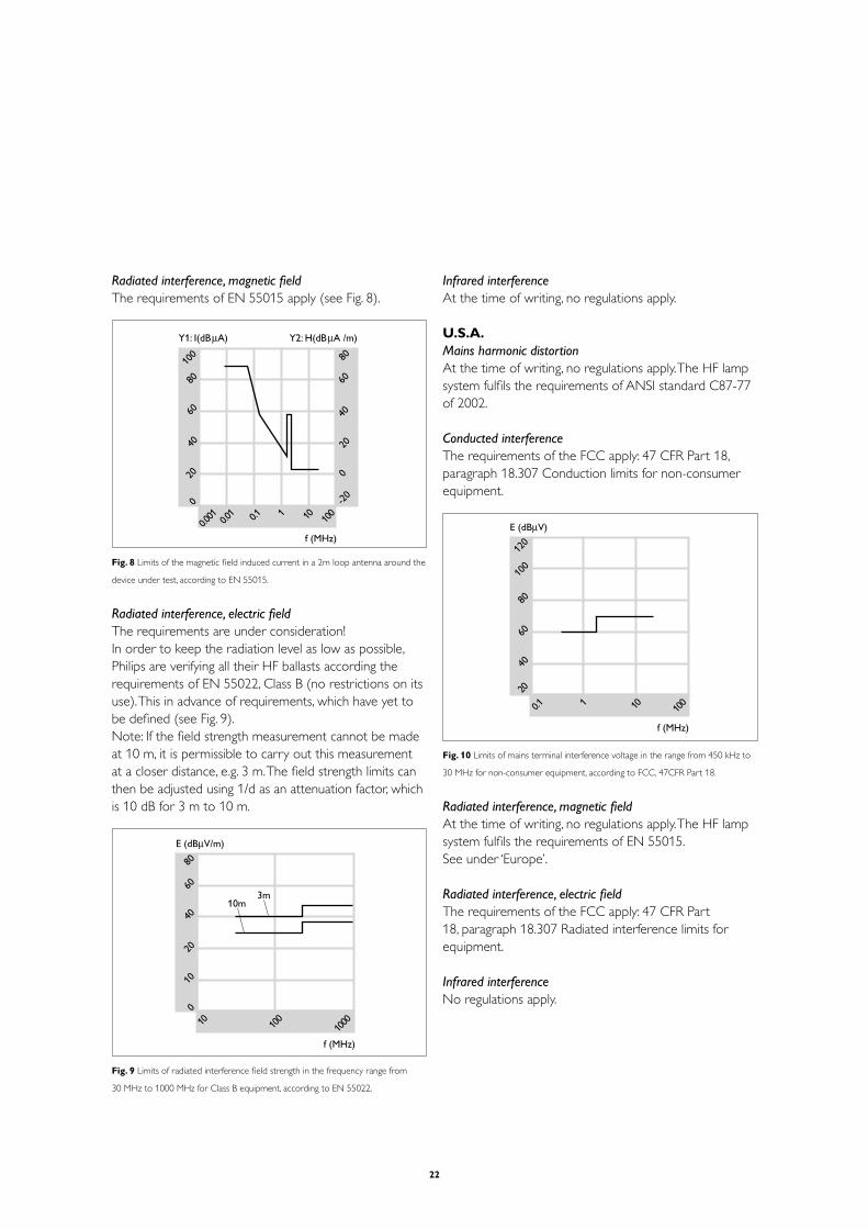
Radiated interference, magnetic fieldThe requirements of EN 55015 apply (see Fig. 8).
001
08
06
04
02
0100.0
10.01.0 1 01 001
Y1: I(dBµA) Y2: H(dBµA /m)
f (MHz)
06
04
02
0
02-
08
Fig. 8 Limits of the magnetic field induced current in a 2m loop antenna around the
device under test, according to EN 55015.
Radiated interference, electric fieldThe requirements are under consideration! In order to keep the radiation level as low as possible, Philips are verifying all their HF ballasts according the requirements of EN 55022, Class B (no restrictions on its use). This in advance of requirements, which have yet to be defined (see Fig. 9).Note: If the field strength measurement cannot be made at 10 m, it is permissible to carry out this measurement at a closer distance, e.g. 3 m. The field strength limits can then be adjusted using 1/d as an attenuation factor, which is 10 dB for 3 m to 10 m.
08
06
04
02
01
001 0001
001
E (dBµV/m)
f (MHz)
10m3m
Fig. 9 Limits of radiated interference field strength in the frequency range from
30 MHz to 1000 MHz for Class B equipment, according to EN 55022.
Infrared interferenceAt the time of writing, no regulations apply.
U.S.A.Mains harmonic distortionAt the time of writing, no regulations apply. The HF lamp system fulfils the requirements of ANSI standard C87-77 of 2002.
Conducted interferenceThe requirements of the FCC apply: 47 CFR Part 18, paragraph 18.307 Conduction limits for non-consumer equipment.
021
001
08
06
04
021.0 1 01 001
E (dBµV)
f (MHz)
Fig. 10 Limits of mains terminal interference voltage in the range from 450 kHz to
30 MHz for non-consumer equipment, according to FCC, 47CFR Part 18.
Radiated interference, magnetic fieldAt the time of writing, no regulations apply. The HF lamp system fulfils the requirements of EN 55015.See under ‘Europe’.
Radiated interference, electric fieldThe requirements of the FCC apply: 47 CFR Part 18, paragraph 18.307 Radiated interference limits for equipment.
Infrared interferenceNo regulations apply.

23
2.3.4 Luminaire designBasic rules The degree of electromagnetic compatibility is basically determined by the HF ballast concept in combination with the luminaire design. Taking the following basic rules into consideration will optimise the EMC behaviour of the system and help to fulfil the requirements. The basic rules are valid for both PL and TL applications where functional and/or protective earth is required. Functional earth can be required in order to fulfil the EMC requirements or to guarantee proper operation of the system. It means that an ignition aid or other metal surfaces are necessary, which should be connected electrically to the housing of the HF ballast.
1. Ensure a firm electrical connection between the HF ballast and the metal luminaire.
The contact resistance has to be as small as possible, so affix the HF ballast directly to the luminaire. The use of additional mounting plates or several junctions has a negative influence on EMC.
2. keep the lamp wiring short. Avoid redundant wiring, e.g. loops. The so-called ‘hot’
wires (see Section 4.1.13) should be the shortest.
3 Keep the mains wiring well away from lamp wiring Ensure that the mains wiring inside the luminaire is
as short as possible. Minimise stray capacitance by ensuring that mains wiring does not run parallel to lamp wiring.
4 Provide good electrical contact between the metal luminaire and reflector and/or louvre.
5 Use a shielding around the lamp, well connected to the luminaire.
This will help to reduce surroundings currents.
6 Minimise capacitance between wires and luminaire. If possible, mount the lamp wiring on spacers.
ScreeningIn the following section the effect of screening will be dealt with. The basic concept is illustrated, and the basic rules governing screening are presented in a number of practical examples. With good engineering judgement, various combinations of the examples presented here are possible.
Effect of screeningFig. 11 (a and b) shows the effect of screening on the axial magnetic field. This magnetic field will be reduced by induction currents in the shielding. A good conducting material is necessary, but this need not necessarily be connected to the circuit or earth.
H
Fig. 11a Magnetic field, not screened.
H
Fig. 11b Magnetic field, screened.
E
Fig. 11c Electric field, radial.
The electric field, which is always radial (Fig. 11c), will be reduced by a capacitive screening. This will allow currents to flow back to the circuit, resulting in a low surroundings current. The shielding must also be of good conducting material and must have low resistance to the HF ballast!

24
Basic conceptA basic screening is represented in Fig. 12. The mounting plate has been used as a reflector and as a screening, and it has good electrical contact with the HF ballast. Wires are short. Stray capacitance between lamp and wires and between individual wires is low.
HF ballast
mounting plate
Fig. 12 Basic concept of luminaire design.
BattensFig. 13a shows a properly assembled batten with reflector. Mains wiring within the housing has been kept as short as possible, so cross-talk is virtually eliminated. The lamp wiring is redundant, see rule 2 and the ‘hot’ side is the shortest. The reflector acts as a shield and is well connected to the HF ballast with no intermittent contacts.
HF ballast
Fig. 13a Batten with reflector.
Fig. 13b shows a poor assembly. Basic Rule 3 (see above) has been broken. Due to stray capacitance, cross-talk between mains and lamp wiring will occur. Major problems will arise when if the long wire is also ‘hot’, see Rule 2.
HF ballast
Fig. 13b Poor assembly of batten with reflector.
LuminairesThe following is valid for both surface-mounted and recessed luminaires.
Fig. 14a shows an assembly similar to that depicted in Fig. 13a. Wiring is close to the (metal) luminaire. The HF ballast makes good contact with the luminaire. The mains wiring is short. The luminaire acts as a shielding, so magnetic and electric fields are small.
HF ballast
Fig. 14a Luminaire with wiring close to the luminaire.
An assembly like the one illustrated in Fig. 14b is also allowed. Notice that the ‘hot’ wire is the shorter.
HF ballast
Fig. 14b Similar to Fig. 14a; notice that the ‘hot’ wire is the shortest.
Fig. 14c shows a construction that breaks with Rule 1. Electrical contact between HF ballast and luminaire is poor. Unnecessary junctions between ballast and housing are introduced, with increased change of poor electrical contact. At the same time, temperature householding becomes poor.
HF ballast
Fig. 14c Luminaire with poor electrical contact between HF ballast and luminaire.
For a twin-lamp luminaire, a construction such as that shown in Fig. 14d can be used. Mounting the HF ballast between the lamps is preferred to mounting it to one side. Long lamp wiring is close to the lamps, so loops are kept small, see Rule 2.

25
HF ballast
Fig. 14d Mounting of the HF ballast in a twin-lamp luminaire.
A PL application is shown in Fig. 14e. Compared to ‘TL’ luminaires, no special constructions are necessary. In fact wiring can be kept even shorter in this case, because the lamp connections are on one side of the lamp.The alternative construction shown in Fig. 14f is not recommended. For both PL and TL it is best to place the ballast between the lamps and not at the side.
HF ballast
Fig. 14e Mounting of the HF ballast in a PL application.
Generally speaking, the wiring for each lamp in a multiple lamp version should have the same length. This will also avoid differences in lumen output. This is especially important for the ‘hot’ side of the ballast.
HF ballast
Fig. 14f This construction of the HF ballast in a PL luminaire is not recommended.
Master-slave applicationSeveral applications require two luminaires to be operated from one HF ballast. Fig. 15 shows the preferred construction. It is important that mains wiring be led out as close to the ballast as possible, and ‘hot’ lamp wiring be the shortest.The RFI behaviour of the master/slave luminaire depends on the kind of cable used. Shielded wire will reduce RFI, but will increases cable capacity.
HF ballast
Fig. 15 Preferred construction of one HF ballast operating two luminaires.
Reflectors and louvresIn most types of luminaires a reflector or a louvre can be used. These are of conducting material (steel or aluminium). The constructions depicted in Fig16 are preferred.In Fig. 16a the reflector acts as a shield. Rule 3 is optimised. Provided the reflector makes good electrical contact with the luminaire, the lamp will have no stray capacitance to the wiring, It should be realised, however, that the shielding function can only be effective if a low ohmic contact resistance between reflector and luminaire is established. For high-frequency signals (harmonics of the operating frequency) conductors act as an inductor with high impedance and will therefore no longer represent a low ohmic resistance. Good electrical contact can be obtained with a short earth wire or an earth spring.
short wire earth spring
Fig. 16a Reflector acting as a shield.

26
Fig. 16b Conducting louvre, acting as a shield around the lamp.
In Fig. 16b a conducting louvre has been used in accordance with Rule 5. Surroundings currents to the environment are very low. In this case, to, it is very important to have reliable contacts, because if they are intermittent it will make EMC behaviour even worse. The lamellae should be well interconnected, and the louvre should be connected to the metal luminaire. This to reduce the EMI problems to a minimum.
No functional and protective earthA small number of the HF ballasts (e.g. HF Matchbox) do not require functional and safety earth. For this reason they do not have a provision for earthing the ballast. These ballasts are optimised for applications where there are no conducting surfaces close to the lamp or HF ballast. Indeed, the presence of conducting surfaces can even make the EMC behaviour worse. It is recommended to keep the number of conducting surfaces close to the lamp or HF ballast to a minimum.
In case an HF-Matchbox is mounted in a metal luminaire, the ballast will couple a rather large amount of HF-signal to the luminaire. When connected to earth, this will pollute the mains and will result in non-compliance with the standard. There are 2 proper ways to solve this problem:1. Create space between the ballast and the metal parts;
this decreases the interference (in practice, 18 mm is sufficient)
2. Connect an RFI-filter between the mains-connection and the ballast. A practical solution is applying a standardized mains-filter.
Thus it is necessary to study each individual luminaire to guarantee compliance with the standard.
2.4 The Energy Efficiency IndexThe European Community has agreed upon a new directive for banning electromagnetic control gear for fluorescent lamps. This new directive is based upon the Energy Efficiency Index (EEI) as agreed by the Committee of European Luminaire Manufacturers Association. This ‘Celma’ Components group has made a proposal on how the industry can be more energy efficient in lighting systems, ranking the different ballasts in different classes from A1 to D. A1 is the most efficient system, D the least efficient. From January 1998 the method employed for measuring the energy classification became obligatory. It is to be executed and implemented as laid down in a Cenelec standard.
What does this mean?
May 2002All ballasts with an EEI classification D are banned.
November 2005All ballasts with an EEI classification C are banned.
Some types in the existing range of electromagnetic control gear are classified as EEI C. These will be adapted to B2 to comply with these regulations on soon as possible.
It goes without saying that, thanks to their energy efficiency, this directive stimulates the promotion of our HF fluorescent control gear.
The EEI classification of the ballasts can be found on the product data sheets.
Dimmable electronicA1
Low-loss electronicA2
Standard electronicA3
Extra-low-loss magneticB1
Low-loss magneticB2
Normal-loss magneticC
High-loss magneticD
Phase 2b (2005)Joint declaration: 55% of theballasts soldshould be electronic
Phase 2a (< Oct. 2005)Ban C-class electromagnetic ballastsPhase 1 (< April 2002)Ban D-class electromagnetic ballasts

27
3 Lamps
3.1 RangeThe low-pressure mercury vapour lamp, or fluorescent lamp, is by far the most widespread of all discharge lamp types. It is employed almost universally: in indoor applications like shops, theatres, etc., in social and civil interiors, but also in street and tunnel lighting. The introduction of the more compact versions has led to its application in homes too.There are many different versions of the fluorescent lamp, including very special lamp types used for reprography, disinfecting, sun-tanning, inspection and analysis, various photochemical processes and effect lighting, but they all work on the same principle. It is not the purpose of this Guide to mention all the various types and their sometimes-special gear requirements. Technical aspects of the lamps will only be dealt with in so far as they are directly related to the gear employed. Low-pressure mercury vapour lamps can be divided in five groups:
visible radiation ultraviolet radiation
fluorescent powder mercury atom
electrons
electrode
Fig. 17 Working principle of a tubular fluorescent lamp.
1) Tubular fluorescent lampsThe tubular fluorescent lamp works on the low-pressure mercury discharge principle (Fig. 17). The discharge tube has an electrode sealed into each end and is filled with an inert gas and a small quantity of mercury, the latter being present in both liquid and vapour form. The inside of the tube is coated with a mixture of fluorescent powders. These convert the ultraviolet radiation of the mercury discharge into longer wavelengths within the visible range. A great many different fluorescent powders or ‘phosphors’ are available for almost any desired colour temperature and colour rendering characteristic.Unlike an incandescent lamp, a fluorescent lamp cannot be connected directly to the mains. Some device to limit

28
improved efficacy and lumen maintenance are in this category.
d) The new range of straight TL5 lamps, with higher wattages than the miniature lamps and the benefits of the ‘TL’D Master lamps. They are about 5 cm shorter than the equivalent T8 types and are only operated on HF gear. The reason for the reduced length is that optimum compatibility with the most common standard European ceiling systems is obtained that way.
There are two ranges: ‘TL’5 HE 14, 21, 28 and 35 W High Efficiency lamps. ‘TL’5 HO 24, 39, 49, 54 and 80 W High Output lamps.
2) Bent fluorescent lampsa) The circular ‘TL’E lamp has a special 4-pin lamp cap
(G10q) and a diameter of 29 mm (code T9). They are available in lamp wattages of 22-32-40-60 W and can be stabilised with electronic or electromagnetic ballasts.
b) The U-shaped ‘TL’U has the standard G13 lamp caps and a diameter of 31 mm or 25 mm. Available in lamp wattages 20-40-65 W and are stabilised on electronic or electromagnetic ballasts.
c) The new ‘TL5’C (Circular) lamps with lamp cap 2GX13 are in 22, 40, 55 and 60 W with a diameter of 18 mm. They can only be stabilised with HF gear.
d) The PLQ, this is the Philips version of the 2D lamp.
3) Non-integrated compact fluorescent lampsStarting from the straight fluorescent lamp, reduction of the tube length and tube diameter (10 - 16 mm) and combination of two or more such small tubes into one lamp, has led to the PL lamp family with a considerably reduced lamp length. In this way a wide lumen package in small dimensions is obtained. This offers considerable energy savings when used as a replacement for incandescent lamps.In the case of non-integrated lamps, the lamp and ballast are separated.In principle they can be sub-divided as follows:- The PL-S and PL-L with 2 parallel tubes - The PL-C with 4 tubes in square formation- The PL-T with 6 tubes.
The parallel tubes are connected by bends or bridges, so electrically they are one tube.Apart from this, various colours are available, and most
the electric current flowing through it must be included in the circuit. This device can be an HF ballast or an electromagnetic ballast with starter. To facilitate starting, the electrodes of most fluorescent lamps are preheated prior to ignition, which is accomplished by means of a preheat current. Starting without preheating of the electrodes is also possible, but at the cost of lamp life, as most lamps are not designed for so-called cold ignition.Some types in the Philips ‘TL’ lamp range, the so-called cold-start lamps (‘TL’S, ‘TL’R, ‘TL’X) and preheat starterless lamps (‘TL’RS, ‘TL’M) require special gear, which is not covered in this Guide.
The tubular ‘TL’ fluorescent lamp group can be further sub-divided as follows (see Fig. 18):
T12
T8
T5
Fig. 18 Comparison of tube diameter of different ‘TL’ lamps.
a) Straight miniature lamps with G5 lamp cap, with a diameter of 16 mm (code T5, which means that they have a diameter of 5 times 1/8 inch) and with a length dictated by the wattage (4 to 13 watt) and by common building modules. This type of lamp can be stabilised with both electromagnetic and electronic (HF-M) gear.
b) Straight ‘TL’ lamps with a diameter of 38 mm (code T12) and with a length dictated by the wattage and by common building modules. These so-called ‘old’ or ‘thick’ ‘TL’ lamps are stabilised by electromagnetic gear. These lamps are only used in special applications; e.g. cold store.
c) Straight ‘TL’D lamps with G13 lamp cap and 26 mm diameter (code T8), these are the most common lamps. This most popular krypton-argon-filled type can be stabilised with both electronic and electromagnetic gear. Also the ‘TL’D Super 80 Master lamps with

29
- 2-pin version, with the starter incorporated in the lamp cap, stabilised with electromagnetic gear, and
- 4-pin version stabilised with electromagnetic or electronic gear.
Due to the different wattages, there is for safety reasons a wide variation in lamp caps, information on which can be found in the lamp documentation. Lamp and gear are separated, giving more freedom to the luminaire designer and an increased lifetime of the lighting system, since the lamps can be replaced.
4) Integrated compact fluorescent lampsa) The PL lamp family
The arc tubes and the electronic gear are integrated to form one complete lamp with a standard lamp cap: E14, E27 or B22. The PL lamp is available in different wattages as PL*Electronic/C, PL*Electronic /D (Decor) and PL*Electronic/T for the mains voltage range 230-240 V/50-60 Hz.
3.2 StabilisationAs described in Section 2.1: the main ballast function is to limit the lamp current, as a fluorescent lamp cannot function properly when it is operated directly on the mains voltage. The first and foremost function of a ballast is to limit the electric current passing through the lamp to a value prescribed for that particular lamp rating. All discharge lamps need such a current-limiting device because they have a negative voltage-current characteristic (see Fig. 19).
V
I
Fig. 19 Current/voltage characteristic of a gas discharge (simplified).The voltage
required decreases as the current increases.The characteristic is negative,meaning
that the current will increase without limit if no measures are taken.
The presence of an electromagnetic ballast between the lamp and the mains-voltage connection (Fig. 20) limits the current flowing through the lamp.
Ib
Il
La
B Vl
Vm
+
-
+ - + -
0
S
Fig. 20 Current limitation by means of a ballast in a simple discharge circuit.
The lamp current – being equal to the ballast current supplied to the lamp – is now fixed by the quotient of the ballast voltage and the ballast impedance. As the ballast voltage is the difference between the mains voltage and the lamp voltage, the maximum lamp current is limited by the mains voltage. In this way a stable operating point is obtained for all mains voltages higher
Ilamp
= Iballast
Iballast
= Vballast
/ Zballast
Ilamp = (Vmains - Vlamp) : Zballast
V
ballast = V
mains - V
lamp
than the minimum voltage Vmin
(see Fig. 21).
V
I
Vlamp + Vballast
V ballast
Vlamp
mV.nimV
Fig. 21 Current/voltage characteristic of a circuit with a ballast in series with the
lamp.Thanks to the ballast,the required lamp voltage increases with increasing lamp
current, leading to a stable situation.
Another very important function of the electro-magnetic ballast is to keep the current of the lamp within certain margins so as to prevent too high a temperature in the cathodes, which would result in a diminished lamp life. The power of the lamp is equal to the lamp voltage Vla times the lamp current Ila times a constant, which is called the lamp factor (α
la):
types are available in two versions:

30
Pla = Vla . I
la . α
la
The lamp factor αla depends on the shape of the lamp voltage and the lamp current, and is therefore also called the ‘shape factor’. The value depends on the method of stabilisation and is approx. 0.8 for electro magnetically stabilised lamps and 0.99 for HF stabilised lamps (see Section 3.4). In stable operation the voltage across the lamp is rather constant under all circumstances. Therefore the lamp power (and so the light output) is depends mainly on the lamp current.The level of the mains voltage is important, as well as the impedance of the ballast. The influence of the frequency of the mains voltage is a hidden factor : this variable influences the impedance of the choke ballast, as Z = ωL with ω = 2πf (f = frequency). The inductance L is depends on the number of copper windings and the dimensions and material of the core of the ballast. From this it follows that the higher the frequency, the smaller the ballast can be. With the electromagnetic ballast for 50 or 60 cycles we need a ‘big’ copper/iron ballast, while in the HF ballasts with much higher operating frequencies (see Section 3.4) a small ballast with ferromagnetic material can be e1mployed.
3.3 Ignition and run-upIn most cases a cold tubular fluorescent lamp will not start when the mains voltage is applied. This is because the ignition voltage is usually higher than the mains voltage. Some sort of starting aid is therefore needed to ignite the lamp. In practice, this involves one or more of the following solutions:- Preheating the electrodes to facilitate electron
emission.- Providing an external conductor on or near the lamp
tube, which is either floating, earthed or connected to one of the electrodes (TLM lamps). The electric field so created facilitates the initial discharge. An alternative solution, which serves the same purpose, is the provision of an internal conductive coating on the tube wall.
- Providing an internal auxiliary electrode in the form of one or two metallic strips along the inside of the tube.
- Providing a voltage peak sufficiently high to initiate the discharge.
- Or a combination of the measures described above
The voltage level at which a fluorescent lamp will ignite is called its ignition voltage. In most lamp types special measures have been taken in the construction of the lamp to keep this ignition voltage as low as possible: the use of a starting gas as a Penning mixture (see Fig. 22) and the application of a starting aid to trigger the initial ionisation of the gas (‘TL’M) are examples of this.
Vst
argon in neon (%)
0 5.0 0.1
Fig. 22 Starting voltage (Vst) as a function of percentage (%) of argon to neon
(Penning effect).
There are three principal ways of igniting the lamp:1) The cold start: ignition is obtained by applying a high
initial voltage to the lamp electrodes. Immediate ignition is obtained without any preheating. This method of ignition needs rigid/robust lamp electrodes (as with the ‘TL’D lamps), a rather high ignition voltage ( > 800 Vrms) and enough energy to pass from the initial ignition to the stable burning situation. This procedure is used in the HF-Basic, e-Kyoto and HF-M Blue ballasts and is the reason that the switching lifetime of the lamps is less than in the next two systems.
2) The warm start: by preheating the lamp electrodes and – once they are at emission temperature – applying a peak voltage just high enough to initiate the discharge. The electrodes can be thinner and the applied starting voltage lower (see Fig. 23). The preheat time must be long enough. For the warm start with an HF ballast a preheat time of approx. 1 second is needed with the correct current, whilst the open-circuit voltage of the lamps is low enough to prevent ignition at this stage. At the end of this time a higher open-circuit voltage will ignite the lamp reliably. Thanks to this procedure, the switching lifetime of the lamps is nearly independent of the switching cycle (HF-P, HF-R, HF-M Red).

31
02-0 02 04 06
ignition voltage
ambient temp. (˚C)
cold start preheated start
Fig. 23 Influence of ambient temperature on the required ignition voltage,both with
cold and with pre-heated (warm) start.
3) The rapid start: here a certain ignition voltage and pre-heat current are supplied simultaneously to the lamp. As long as the cathodes are not hot enough, the lamp will not ignite. When, after a certain time, the cathodes are hot enough, the lamp will ignite at the applied ignition voltage (see Fig. 24 point P of the so called Z-curve).
temp. (˚C)
Vst (V)
003005
007009
003
052
002
051
e
P
cold
rapid
warm.
Fig. 24 Starting voltage (Vst) as a function of electrode temperature.Point e repre-
sents the emission temperature, viz.the point at which the electrode emits sufficient
electrons.
Glow-switch starters do function in combination with these ignition systems: as the closing time of the bimetallic contact is not well defined (see Section 5.2: Starters), it is not certain that the lamp electrodes are at emission temperature when the glow-switch starter opens. Also, the height of the ignition peak can vary rather a lot. This can be noticed in practice when the glow-switch starter works several times before the lamp ignites. This flickering gets
worse at low ambient temperatures, at low mains voltages, or with aged lamps.The starting of amalgam lamps, such as the SL and PL-T lamps, requires a higher ignition voltage than that of the standard fluorescent lamps, especially below 100 deg C.
The initial ignition (first break-down) results in a low electric current between the two main electrodes (the gas goes from a isolator to a conductor). After this initial breakdown many free electrons are made in the discharge, resulting more or less in the nominal lamp current, depending on the ability of the system to allow a high enough lamp voltage. During this phase a small portion of the electrode is heated up to a temperature, which enables thermionic operation of the lamp. This process is called glow to arc transition.
After ignition, the lamp will heat up and the temperature of the coldest spot will rise, causing a rise in the mercury vapour pressure, which determines the arc voltage of a given lamp. In what time thermal equilibrium is reached depends on the lamp type and its surroundings (ambient temperature, open/closed luminaire). Normal ‘TL’ lamps in normal applications have a run-up time of 2-3 minutes to reach stable lamp voltage and a level of 90 per cent of the maximum light output. The run-up phase for PLT lamps is longer, due to the amalgam. It takes more time for the mercury to evaporate from the amalgam, so it takes longer to reach the stable lamp voltage. But a lighting level of 80 per cent is attained within one minute also with these lamps (see Figs 25 and 26).
ignition time (s)
ambient temp. (˚C)
001
08
06
04
02
001-
5- 0 5 51 52
Vnom (base down)
Vnom (base up)

32
Φ (%)
t (min)
001
08
06
04
02
00 1 5 01 02 52
Fig. 25 Typical ignition time and run-up behaviour of an SL lamp operated on an
electromagnetic ballast.
ignition time (s)
ambient temp. (˚C)
0.2
5.1
0.1
5.0
002-
01- 0 01 02 52
210-240 V mains voltage
Φ (%)
t (min.)
001
08
06
04
02
00 1 5 01 02 52
Fig. 26 Typical ignition time and run-up behaviour of a PL*E/C lamp.
3.4 Lamp behaviour as a function of the frequencySupplied by a mains voltage of 230 V/ 50 Hz and stabilised with an electromagnetic ballast, the lamp voltage and lamp current of a fluorescent lamp are not pure sine waves (see Fig. 27).
005
001
005-
V
VmIlVl
t
Fig. 27 Waveform of mains voltage (Vm),lamp voltage (V
l) and lamp current (I
l).
Every time the current passes through zero, the lamp is ‘out’ and needs a certain re-ignition voltage peak to re-ignite. The electrical energy supplied to the lamp in the form of Vla and Ila is transformed into the lamp power Wla with a certain lamp factor, called αla, according to the equation:
Wla = α
la . V
la . I
la
Typical values for an electro magnetically stabilised 50 Hz ‘TL’D 36W lamp are: V
la = 103 volt
Ila = 0.44 ampere
Wla = 36 watt
so αla = 0.79
The period of time that a lamp is ‘out’ will decrease by raising the frequency of the lamp current, resulting in a lower re-ignition peak. At increasing frequency both lamp current and lamp voltage will become more sinusoidal, resulting in a higher lamp factor α
la (see Fig. 28).
Typical values for a 36 W ‘TL’D lamp stabilised by HF gear are: V
la = 103 volt
Ila = 0.32 ampere
Wla = 32 watt
so αla = 0.99

33
50 Hz
100 Hz
200 Hz
800 Hz
8000 Hz
Fig. 28 Lamp voltage as a function of frequency for a ‘TL’D 36 W lamp.
As a result of the improved lamp factor, the lamp current can be lower for a given wattage in the discharge. HF operation gives an efficacy gain of about 10% (see Fig. 29). This gain is due to the almost diminished anode voltage and a higher efficacy of the arc amongst others caused by the lower lamp current.
011
001
0 0000100002
00003
Fig. 29 Luminous flux (Φ) of a fluorescent lamp as a function of supply frequency
(f) at constant lamp factor.
For low-pressure mercury vapour lamps with a TLD diameter at a fixed lamp power, a 10 per cent higher efficiency can be achieved at frequencies of more than 10 kHz (for smaller diameters this border frequency leis at higher frequencies). To avoid audible disturbance, the working frequency must be more than 20 kHz. But while
much higher frequencies will result in a smaller stabilisation coil, they will also result in higher losses in the electronic switching devices and more radio-interference problems. Different operating frequencies are therefore used, mainly depending on lamp type. The practical working frequency is between 24 kHz and 31 kHz and between 40kHz and 50 kHz for most HF-P ballasts, while the HF-Matchbox operates with a frequency lower than 30 kHz. All HF-B and HF-R ballasts and also the HF-P for TL5 C, PLL 18/24 and PLT/PLC lamps operate above 42 kHz. 3.5 Lamp and system efficiency
The lamp efficiency is expressed in a figure called the luminous efficacy. It indicates the efficiency of the lamp in transforming electrical energy into light and is expressed in lumen per watt (lm/W). The light or radiated power is ‘weighed’ according to the eye-sensitivity curve for visible light.
The amount of light generated by a lamp is called the luminous flux or lumen output. It is a variable figure, depending on many factors including the phosphors employed (colour, kind of phosphor), lamp tube dimensions, gas mixture and pressure, and so forth (see Fig. 30 and Table).
lamp lengtha)
c)
b)
d)
p (torr)
η (%)
Il
η η
η
lamp diameter
001
89
69
491 2 3
Fig. 30 Lamp efficacy as a function of lamp length (a), lamp diameter (b), argon
pressure (c) and current (d).
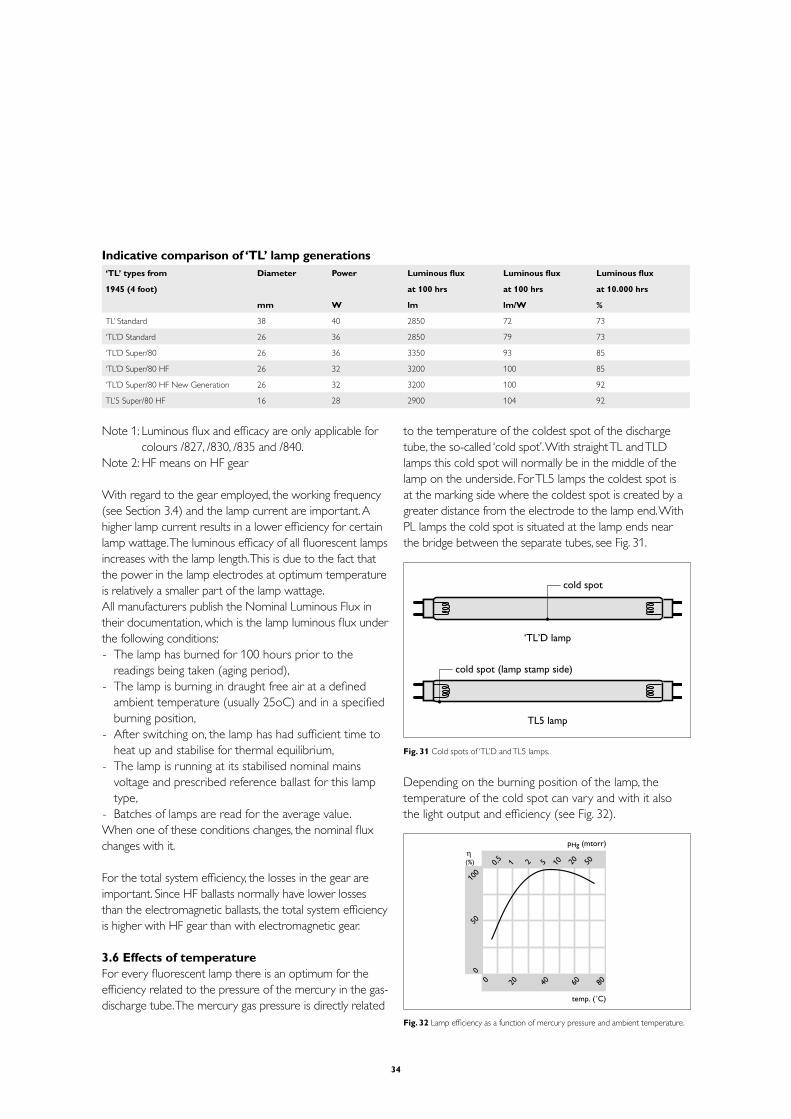
34
Indicative comparison of ‘TL’ lamp generations‘TL’ types from
1945 (4 foot)
Diameter Power Luminous flux
at 100 hrs
Luminous flux
at 100 hrs
Luminous flux
at 10.000 hrs
mm W lm lm/W %
TL’ Standard 38 40 2850 72 73
‘TL’D Standard 26 36 2850 79 73
‘TL’D Super/80 26 36 3350 93 85
‘TL’D Super/80 HF 26 32 3200 100 85
‘TL’D Super/80 HF New Generation 26 32 3200 100 92
TL’5 Super/80 HF 16 28 2900 104 92
Note 1: Luminous flux and efficacy are only applicable for colours /827, /830, /835 and /840.
Note 2: HF means on HF gear
With regard to the gear employed, the working frequency (see Section 3.4) and the lamp current are important. A higher lamp current results in a lower efficiency for certain lamp wattage. The luminous efficacy of all fluorescent lamps increases with the lamp length. This is due to the fact that the power in the lamp electrodes at optimum temperature is relatively a smaller part of the lamp wattage.All manufacturers publish the Nominal Luminous Flux in their documentation, which is the lamp luminous flux under the following conditions:- The lamp has burned for 100 hours prior to the
readings being taken (aging period),- The lamp is burning in draught free air at a defined
ambient temperature (usually 25oC) and in a specified burning position,
- After switching on, the lamp has had sufficient time to heat up and stabilise for thermal equilibrium,
- The lamp is running at its stabilised nominal mains voltage and prescribed reference ballast for this lamp type,
- Batches of lamps are read for the average value.When one of these conditions changes, the nominal flux changes with it.
For the total system efficiency, the losses in the gear are important. Since HF ballasts normally have lower losses than the electromagnetic ballasts, the total system efficiency is higher with HF gear than with electromagnetic gear.
3.6 Effects of temperatureFor every fluorescent lamp there is an optimum for the efficiency related to the pressure of the mercury in the gas-discharge tube. The mercury gas pressure is directly related
to the temperature of the coldest spot of the discharge tube, the so-called ‘cold spot’. With straight TL and TLD lamps this cold spot will normally be in the middle of the lamp on the underside. For TL5 lamps the coldest spot is at the marking side where the coldest spot is created by a greater distance from the electrode to the lamp end. With PL lamps the cold spot is situated at the lamp ends near the bridge between the separate tubes, see Fig. 31.
‘TL’D lamp
cold spot
cold spot (lamp stamp side)
TL5 lamp
Fig. 31 Cold spots of ‘TL’D and TL5 lamps.
Depending on the burning position of the lamp, the temperature of the cold spot can vary and with it also the light output and efficiency (see Fig. 32).
5,0 1 2 5 01 02 05001
05
00 02 04 06 08
pHg (mtorr)
(%)
temp. (˚C)
η
Fig. 32 Lamp efficiency as a function of mercury pressure and ambient temperature.

35
The same lamp mounted in a closed luminaire will reach a higher temperature than in an open luminaire, so the lumen output will differ at the same ambient temperature. Graphs are available for all lamps, showing the relative light output of the bare lamp as a function of the ambient temperature. The influence of the luminaire must be found separately by measurement (see Figs 33-35).
warmest regionof the housing
Fig. 33a Warmest region on the housing of a PL lamp.
cool spots bridge discharge tube electrodes
Fig. 33b Cold spot at the tube ends near the bridge of a PL lamp.
001
08
06
04
02
002-
0 02 04 06
Φ (%)
ambient temp. (˚C)
Fig. 33c Relative luminous flux of PL lamps as a function of the ambient tempera-
ture and burning position.
A
S
H
B
W
5 mm
warmest regionof the housing
B = ballastA = amalgamS = cold spot
W = wallH = auxiliary amalgam
Fig.34 Warmest region on the housing and cold spot inside an SL lamp.
Φ (%)
ambient temp. (˚C)
001
09
08
01 03 05
Φ (%)
ambient temp. (˚C)
001
09
08
01 03 05
ambient temp. (˚C)
a)
c) d)
b)
001
09
08
01 03 05
Φ (%)
Φ (%)
ambient temp. (˚C)
001
09
08
01 03 05
Fig. 35 Relative luminous flux of different SL lamps as a function of lamp ambient
temperature. a) SL*9/13 base up,b) SL*9/13 base down,c) SL*18/25 base up,d)
SL*18/25 base down.
In principle, the gear employed has limited influence on the temperature of the cold spot and consequently on the light output. With TL5 lamps additional heating will cause a shift of the temperature at which the maximum light output occurs in closed luminaires will the inside temperature be influenced by the watt losses of the gear. So HF ballasts will have less influence than electromagnetic gear, due to their lower losses.The optimum mercury vapour pressure for tube diameters of 26 and 38 mm is about 0.8 Pa, and this is reached at a tube wall temperature of about 40oC. This is not much higher than the usual ambient temperature of 20 to 25oC, and the heat generated by the discharge is sufficient to reach the required operating temperature of 400C without special measures.If the temperature is low (for example, outdoor lighting in winter), it is desirable to operate the fluorescent lamp in a well-closed luminaire.The new TL5 lamp is optimised for an ambient temperature of 35oC, this corresponds with a wall temperature of about 45oC. For the luminous flux as a function of the ambient temperature, see Fig. 36 a/b.If the wall temperature is above the ideal operating temperature, artificial cooling of the lamps might be useful, but this requires extra facilities.

36
02-0 02 04 06
ambient temp. (˚C)
‘TL ’ D + electromagnetic ballast‘TL ’ D + Philips electronic ballast
Φ (%)
001
02
04
06
08
0
Fig. 36a Luminous flux as a function of ambient temperature for ‘TL’D lamps
operated on different control gear.
Φ (%)
001
02
04
06
08
001 02 03 04 05
ambient temp. (˚C)
‘TL ’ D‘TL ’ 5
Fig. 36b Comparison of luminous flux as a function of ambient temperature
between ‘TL’D and TL5 HE lamps.
By applying amalgam it is possible to guarantee a light output of more than 90 per cent of the maximum in the amalgam temperature region between 55oC and 120oC (see Fig. 37). This measure is taken in the SL, PL-T, PL*E-T and QL lamps, where the minimum temperature inside the glass tube is about 90oC.
05
02
015
2
15.0
2.0
0 05 001051
002
pHg (mtorr)
temp. (˚C)
amalgam
Hg
90%
100%
90%
Φ
Fig. 37 The influence of amalgam on the mercury pressure and on the luminous
output of an SL lamp.
3.7 Optimum operationAs has been said in Section 3.1, there are many different types of fluorescent lamps, each in different lamp wattages, lamp voltages and lamp currents. Although the differences in behaviour are not so wide as with high-intensity gas-discharge lamps (SON-SOX-HPL-HPI-MHD), each type has its own pros and cons.What they have in common though, is that they need the correct ballast and ignition system for optimum performance. In fact, each type needs its own specific gear. For this reason one should take care to use the recommended gear in combination with the chosen lamp. Especially when using electromagnetic ballasts, the combination must be correct for the available mains voltage (220, 230 or 240 V / 50 or 60 Hz). HF ballasts cover a wider mains-voltage range, which can be found in the product data sheets.When the wrong components are chosen, one can expect problems: for example, with:- lifetime of lamps and gear- temperatures- starting/run-up- stable burning- radio interference- light output

37
3.8 Lamp life and depreciationThe data published by lamp manufacturers for life expectancy and lumen depreciation are obtained from large representative groups of lamps in laboratory tests under controlled conditions (see for example Figs 38 and 39). These include, amongst others:- nominal supply voltage and appropriate circuitry- specified burning position- specified switching cycle- free-burning, mounted on test racks (not in a luminaire)- no vibrations or shocks- specified ambient temperature, mostly 250CAny change in these circumstances will affect a lamp’s lifetime.
burning time (hrs)
life expectancy (%)
001
09
08
07
06
050
inductivecapacitive
000500001
0005100002
001
09
08
07
06
050 0005
0000100051
00002
life expectancy (%)
burning time (hrs) burning time (hrs)
life expectancy (%)
001
09
08
07
06
050 00002
000500001
00051
Fig. 38a Life expectancy curve for ‘TL’D Super/80 New Generation on HF gear ;
warm start.
Fig. 38b Life expectancy curve for ‘TL’D Super/80 New Generation on HF gear ;
cold start.
Fig. 38c Life expectancy curve for ‘TL’D Super/80 New Generation on conventional
gear.
Φ (%)
burning time (hrs)
001
09
08
07
06
050 0005
0000100051
00002
Φ (%)
burning time (hrs)
001
09
08
07
06
050 0005
0000100051
00002
Φ (%)
burning time (hrs)
001
09
08
07
06
050 0005
00001
0005100002
Fig. 39a Lumen maintenance in % for ‘TL’D Super /80 New Generation and TL5.
Fig. 39b Lumen maintenance in % for ‘TL’D standard colours on conventional gear.
Fig. 39c Lumen maintenance in % for ‘TL’D /90 de Luxe colours.

38
The type of circuitry can also influence lamp life or lumen maintenance. For example, due to the controlled starting process the life expectancy of fluorescent lamps operated on a warm-start HF ballast is higher than on electromagnetic gear.
Lamp life on electromagnetic L and LC circuitsFor conventional, electromagnetic operation, the electrodes are preheated when the switch starter is closed. At the moment the switch starter opens, the lamp may or may not ignite. Whether or not the lamp will ignite depends on the ‘produced’ ignition voltage. This again depends on the mains voltage at the moment the switch starter opens. If the lamp does not ignite, more attempts will follow until the lamp does ignite.Lamp life is also influenced by the type of starter used. Generally, the use of electronic starters, such as the Philips types S2-E or S10-E, has a positive effect on lamp life.For conventional operation, important differences exist between L (inductive) and LC (with series capacitor) operation. For LC operation the preheat current through the electrodes is much lower than with L operation, which results in a lower electrode temperature at ignition. After the lamp is ignited, the lamp current is higher than with L operation. As a consequence the electrode temperature is then relatively high.Because of these differences it is not possible to have the optimum switching behaviour for both L and LC operation. A compromise has to be chosen. The situation is further complicated by the rather strong influence of two different operation conditions:a) Preheat current and lamp current increase with the
mains voltage. In general, lamp life will decrease with increasing mains voltage.
b) The necessary ignition voltage is temperature dependent. This means that results of switching tests will be different for different ambient temperatures.
Lamp life on warm-ignition ballast (HF-P, HF-R)With ‘warm-ignition’ HF ballasts, the electrode is preheated in a well-defined way. After the preheat time, the lamp is ignited with a sufficiently high voltage. Due to the preheated ignition, the performance on faster switching cycles is very good. Lamp life is also improved for slow switching cycles. This is caused by the optimum relation between lamp current and electrode heating current. The presented lamp life values are the average figures over the lamp and ballast range.
In comparison with conventional operation:- performance on fast switching cycles is improved,- lamp life will not depend on mains voltage (mains
independence!),- lamp life will not depend on ambient temperature.
Lamp life on cold-ignition ballast (HF-Basic, HF-Matchbox, HF-Kyoto)When ‘TL’ lamps are operated without the appropriate electrode preheat current, lamp life will be reduced with more-frequent lamp ignition. In the past, guidelines have been developed to design the cold ignition in such a way that the ‘ignition damage’ is limited. After lamp ignition, the ‘glow-to-arc transition’ has to take place within 100 ms. This is reached when the ballast delivers the appropriate amount of power during the glow phase (defined by IEC). When this is the case, lamp life will be comparable to operation on a conventional L circuit for switching cycles greater than 5 hours.Also important for lamp life is the electrode temperature during operation. For HF operation, the heat balance of the electrode differs significantly from that with conventional operation. Without extra electrode heating, a certain minimum lamp current has to be maintained to obtain the appropriate lamp life. For this reason the so-called I-control has been developed: the electrode current is maintained at the optimum value during both the ignition phase and the normal running, and at all dimming levels and temperatures for all IEC-compliant lamp types (see also Section 3.11).
Another factor influencing the life of fluorescent lamps is the type of phosphors used: the modern lamps with /80 and /90 colours have a considerably lower light depreciation during their burning life than do the lamps with other fluorescent materials, say, colour /33 or /25 (see Fig. 39).
Specific information on lamp life and light depreciation is in most cases available from the local Philips organisation, but not all parameters are measured on a regular basis.
3.9 Influence of switching cycleFluorescent lamps may be required to be switched on and off more than only a few times per 24 hours, especially when they are used in combination with controls such as movement detectors or light cells. The influence of the switching cycle on the lifetime of the different types of fluorescent lamps is different in different lamp circuits.For applications where more that one switch per three

39
hours is required preheated ballasts should be used. If less switching is required also cold start ballast may be used. Note that even in this infrequent switching cycles there will be a better performance of warm igniting ballasts.
For lifetime expectancies and service lifetimes of the various lamps, please be referred to the Lamp Life brochure.
TL-D 80 measured under lab. conditions, service life Between brackets is the number of switching cycles per twenty-four
0
2
4
6
8
10
12
14
16
18
20
0 0.15/0.05 (72x)
0.45/0.15 (24x)
2.45/0.15 (8x)
11.30/0.30 (2x)
Continues operation
HF-P, HF-R, HF DALI
HF-B /MB
Electromagnetic
)0
001x srh( e
miT
hrs on/hrs off
Fig. 40
3.10 Stroboscopic effect and striationsThe stroboscopic effect is the apparent change of motion of an object when illuminated by periodically varying light of the appropriate frequency.
Flicker is the fluctuation of the lamp’s light output on account of movement of the discharge arc on the electrodes or instabilities in the arc.
Striations are noticeable as a pattern of more or less bright regions in the long discharge tube. This pattern can move through the discharge tube. It can appear when the lamp is cold or when the lamp is dimmed down to a low output level.
One or more of these three phenomena may appear, especially in combination with conventional gear (see Section 5.3.17).
In the case of HF ballasts, the first two effects are not noticeable, thanks to the inertia of the fluorescent material, which cannot follow the high operating frequency and also because the ballast limits the light modulation in the 50 Hz mains to a large extent (see Fig. 41).
Fig. 41a Lamp current at 50 Hz operation.
Fig. 41b Luminous flux at 50 Hz operation.
Fig. 41c Lamp current at HF operation.
Fig. 41d Luminous flux at HF operation.
However, at low ambient temperatures and/or at low dimming levels striations can also occur with HF ballasts.

40
3.11 DimmingTo what extent fluorescent lamps can be dimmed, very much depends on the related gear and the dimming circuit. The following general observations can be made:
1) Retrofit lamps such as the SL family and the PL*Electronic/T and /C cannot be dimmed.
2) Two-pin versions of the PL family cannot be dimmed.3) When operated on conventional gear, all ‘TL’ lamps
can be dimmed without any great problems down to approx. 50 per cent light output. Normally, the lifetime of the lamps will certainly not increase, by doing this. If, however, proper measures are taken to keep the lamp electrodes heated, dimming can increase the lifetime of lamps or at least don’t influence it negatively. However this kind of dimming is hardly applied anymore.
4) In combination with the appropriate regulating HF ballast, the 4-pin PL-S/T/C, the PL-L, the ‘TL’D and the TL5 lamps can be properly dimmed and the lifetime of the lamps will increase if the electrodes are heated to the proper level. Please not that without this additional heating the lifetime of the lamp will decrease dramatically, worst case it will diminish to a few hours!! For further information about dimming see also Section 4.2.
Running and dimming conditionsIn a burning lamp the electrode has to be kept at a sufficiently high temperature for good lamp performance. Above a certain limit value the discharge current itself can take care of this. Below this limit value an additional electrode current has to be applied, see Fig. 42.
ILH
ILL
ID
IHH = Lead-High ("total") currentID = lamp (discharge) currentILL = Lead-Low ("heating") current
Fig. 42 Diagram of a lamp electrode with additional electrode current for dimming.
lD = discharge current, ILL = heating current, lLH = ID + ILL (vector sum).
For a good performance, ID, ILL and ILH have to be kept between limits. Example: For 4-pin lamps the following table includes these limits and their mutual relationships.
ID1 ILL2 ILH3
Nominal operation 160 - 240 mA < 200 mA 160 - 270 mA
Dimming operation 20 - 160 mA < 200 mA 175 – 270 mA
1 Discharge currents < 160 mA require additional electrode heating (ILL). Discharge currents > 240 mA will have a negative effect on lamp life.
2 Heating currents > 200 mA will cause accelerated end blackening.
3 ILH has a maximum value to avoid local overheating of the electrodes. In the case of ID < 160 mA, when extra electrode heating is applied, the minimum electrode heating is covered by the lower limit set to ILH.

41
4.1 Electronic high-frequency system4.1.1 Block diagram (see Fig. 43)
mains lamp(s)filter forinterferencesuppression
ballast controller
converterAC/DC
=preconditioner
converterDC/AC
=lamp controller
Fig. 43 Block diagram indicating the main functions of an electronic HF ballast sytem.
The main functions of a ballast has been described in Section 2.1: Main ballast functions.Although the electronic HF ballast system is integrated into one single ‘black box’, its different functions can be divided into a number of individual blocks. In broad outline: after passing a low-pass (RFI) filter, the mains voltage is rectified in an AC/DC converter. This converter also contains the buffer capacitor, which is charged via this DC voltage. In the DC/AC converter the DC voltage is transformed into an HF voltage, which provides the power for the lamp controller. The ballast controller controls all these functions.
4.1.2 Circuit diagram (see Fig. 44)
C
C
2control
electronics
L
N
low-pass filter rectifier buffercapa-citor
HF poweroscillator
lamp stabilisation
+ +
--
S1
S2
1
L
L
Fig. 44 Circuit diagram of an electronic control system
(version with two lamps in parallel).
The low-pass filter has four functions:• Limitation of the harmonic distortion, so that its level
remains within international standards (see Fig. 45).
Im Im
t t
with filter
or
with filterIm
t
without filterUm
t
Fig. 45 Mains voltage and mains current, the latter withoutand with low-pass filter.
• Limitation of radio interference, which would otherwise be injected from the HF ballast into the mains. Here also international standards are to be adhered to.
• Protection of the electronic components against high mains voltage peaks.
• Inrush current limitation. The low-pass filter is fully electronic (HF-B, HF-P, HF-R). The different functions (low-pass filter, RFI suppression,
inrush limiter and transient limiter) are separated (see Fig. 46).
up-converter buffercapacitor half bridge lamp circuit
start/stopcircuit
mainsfilter
mainsrectifier
transientlimiter
Fig. 46 Block diagram of an electronic control system.
The advantages of the fully electronic version compared with the EM version, include: uses less power, lighter, has a high power factor, the light output is independent of mains-voltage fluctuations, and there is no 50 Hz hum.
The rectifier consists of a full diode bridge. The buffer capacitor in principle determines the shape of the lamp current and the mains current. It has to be chosen carefully in order to minimise the modulation in the lamp current (and thus the modulation in the light output). With a ‘high’ capacitor value the modulation in the light output is less than with a ‘low’ capacitor value, but the mains current waveform is more distorted (less sinusoidal), resulting in higher harmonic distortion (see Fig. 47).
Celco high
Celco low
Im
t
Im
t
Ila
t
Ila
t
AC
DC
DC
AC
Im
Umains C lamp
UDC L
rectifier buffer capacitor HF generator
Il
Fig. 47 Circuit with rectifier, energy buffer and HF generator. The curves show the lamp
and mains current at high and low capacitance of the energy buffer for a typical CFL lamp.
4 Electronic lamp control gear

42
Furthermore, the level of the inrush current depends on the value of this buffer capacitor. The bigger the buffer capacitor the bigger the inrush current.The HF power oscillator is the heart of the electronic ballast. Controlled by the ballast controller the semiconductor switches S1 and S2 (Fig. 44) are switched at a frequency ranging from 25 to 100 kHz, so creating an HF square-wave voltage between the points 1 and 2. The frequency is regulated by the ballast controller.The controller contains all necessary sensors and intelligence to manage the mains input and lamp output functions of the electronic ballast, such as the preheating process, lamp power, stop circuit or safety switch-off, mains voltage fluctuations and mains frequency variations and sometimes over-voltage detection.
The HF square-wave voltage is fed to the series connection of the lamp and the HF choke (L in Fig 44 which is the stabilisation coil). In the twin-lamp parallel version both lamp branches are connected in parallel with a choke coil for each lamp (Fig. 44). In the twin-lamp series version and in the single-lamp version, there is only one branch between the points 1 and 2 with one choke coil (see Fig. 48).
L
C2
La La
C1
1
2
C1 < C2
Fig. 48 Twin-lamp series version with only one branch bettween the points 1 and 2
with one choke coil.
Capacitors connected in parallel to the lamps are necessary for the preheating and starting process, among other things. During preheating the current flows through the lamp electrodes and through these parallel capacitors.
4.1.3 Choice of frequencyAs described in Section 3.4 the operating frequency should be above 10 kHz for TLD lamps to obtain 10 per cent more efficacy, compared with the 50 Hz operation, and above 20 kHz to be above the human threshold of audibility. On the other hand, it should be below approximately 100 kHz to limit the losses in the ferrite coils and transistors.
Apart from these considerations there is a third factor to be considered: like all lamps, fluorescent lamps emit not only visible light, but also have a variable amount of infrared emission. Modulated in a high frequency, this can disturb infrared remote controls as used for television sets, audio, video, transmission systems and data communication. The lowest practical frequency for these systems is found in the RC5 system, working on 36 kHz. So the operating frequency for HF fluorescent lamps should not be 18 kHz or 36 kHz. Nowadays the frequency range from 30 kHz to 40 kHz is more or less reserved for IR systems. It is for this reason that various operating frequencies have been chosen for the newer generation of HF ballasts: an operating frequency of about 45 kHz was chosen for the HF-B types, for the PL*E/C system because the distance between lamp and ballast is normally short, and for the HF-R types to create a wide frequency band for dimming purposes (42-90 kHz). On the other hand, one of the reasons for using an operating frequency of 24-31 kHz for HF-P ballasts is to minimise influences on EMC and to achieve maximum lamp cable capacities (see Sections 2.3 and 4.1.19). The HF-Matchbox operates at about 28 kHz.
4.1.4 Ignition and re-ignitionAs described in Sections 3.3 and 3.4 a fluorescent lamp with cold cathodes needs up to an ignition voltage of more than 800 V r.m.s., depending on the lamp type, which means 1500 V peak value. Due to this cold starting process emitter material will sputter away from the lamp electrodes. Frequent switching will thus result in a noticeably shorter lifetime. Another possibility is to bring the lamp electrodes up to their emission temperature before ignition by means of preheating.
Fig. 49 Required ignition voltage as a function of the ambient temperature with
preheated and non-preheated electrodes.

43
Fig. 51 Ignation with a twin-lamp HF ballast.
phase, this voltage will be 500 V, giving the required ignition voltage for both lamps. Once one lamp is ignited, the voltage at point P changes to 300 V, which is divided into 100 V for the lamp and 200 V for the transformer coil L1. As transformer coil L2 is wound in the opposite direction, the open voltage for lamp 2 is still 300 + 200 = 500 V until the second lamp ignites as well.
The run-up time of fluorescent lamps is very short, as the lamps get their nominal lamp voltage almost immediately. But with the amalgam lamps (CFL, PL-T) it takes a few minutes before the amalgam is warmed up sufficiently to evaporate the amount of mercury necessary for the full light output. It can also take a few minutes for the lamp tube to reach its optimum temperature (see Section 3.6: Effects of temperature).
All HF ballasts have an automatic stop circuit. Should a lamp fail to ignite at the first attempt (for example at the end of its lifetime), the electronics switch off the ballast after about 5 s. In this way, the so-called anomalous condition that can be found with starter circuits is avoided, resulting in:- after the switch-off, system losses of only 1 W- no annoying flashes of the non-starting lamp or
heating-up of the lamp caps- no unnecessary radio interference.
After having replaced the lamp, most ballasts (exception: e-Kyoto) are immediately ready for operation again and the lamp starts without having to reset the mains (switching the mains supply off and on again). This means that lamp replacement can be done while the mains power remains on. Although not recommended, this is often done in practice.
Fig. 50 Open circuit voltage of an HF baffast
This is done by applying a frequency different from the operating frequency (normally higher) to the LC starting circuit for about 1.4 second to ensure a low open circuit voltage during the preheat phase (for TL’D this is approx. 250 V) and a sufficiently high preheat current (see Figs 49 and 50). After the preheat time, a voltage of approx. 500 V (depending on the lamp type) is applied, again by changing the frequency, sufficient for reliable ignition during a maximum of approx. 0.2 sec. The lamp ignites at the first ignition peaks and then the ignition voltage stops. After the preheat and ignition phase, the lamp gets its normal operating voltage (between approximately 50 V and 200 V, depending on the lamp type).There are two ways of preheating:- current preheating, with a more or less constant
current through the cathodes in the HF-P- voltage preheating, with a voltage depending on the
actual working frequency (viz. dim level) for the HF-R where the cathode current is higher at lower dimming levels.
Due to this warm start, the lifetime of the lamps is not so much dependent upon the switching cycle as compared with the cold start method and conventional gear.At the moment of ignition, the energy in the LC circuit is high enough to transfer the initial glow discharge into the stable burning discharge. After ignition the electronic ballast adopts its normal operating frequency.No extra voltage is necessary for re-ignition at this working frequency, as the plasma in the discharge remains conductive at this high frequency. Ignition of a twin lamp ballast works on the same principle: in the preheat phase the voltage at point P (Fig. 51) is 300 V. In the ignition

44
4.1.6 Cut-off principleThe cut-off principle minimises the current through the lamp electrodes shortly after the lamp is ignited. Not only does this save energy, it also lowers the temperature at the lamp ends.The standard TL-D lamp is optimised for a tube wall temperature of 400C, which is reached at an ambient temperature in the luminaire of 200 to 250C. The cold spot is in the middle of the lamp (see Fig. 52).
Fig. 52 Cold spot of ‘TL’D and ‘TL’5 lamps.
The TL5, however, is developed to function in smaller luminaires at an higher wall temperature of 450C, which should be reached at an ambient temperature in the luminaire of 350C. The cold spot is at one end of the lamp. Without cut-off (see Fig. 54a), this cold spot would become too warm, meaning that the lamp would function optimally at an ambient temperature of 270C. With cut-off (Fig. 54b), the optimum is reached at an ambient temperature of 350C (see Fig. 53).
Fig. 53 Luminous flux with TL5 and HF-P ballast with and without cut-off.
Should the lamp extinguish as a result of an interruption or dip in the mains voltage, instant re-ignition is guaranteed as soon as the voltage returns.
With the twin-lamp ballasts, the stop circuit switches off both lamps when one lamp fails or when one of them is not connected to the ballast correctly. This is because the ballast control system is comparing both lamp currents and must make them equal in stable operation. If one of the currents is zero after the ignition phase, the other will become zero as well.Sometimes so-called ‘independent lamp operation’ is offered with twin-lamp ballasts. This feature suggests that if, in a twin-lamp system, one of the lamps should fail, the other one will continue to operate. However, with many such twin-ballasts this is only true as long as the system is not switched off. Once the mains is switched off, the intact lamp will fail to ignite at subsequent switch on. There are some special twin-ballasts available that do offer such independent operation, but these are also special as regards their (higher) price.
4.1.5 Ballast typesThe family of electronic ballasts can be divided up in various ways:1) One, two, three or four-lamp versions 2) Standard or regulating (see Section 4.2)3) Warm start (HF-Matchbox red HF-P, HF-R) or cold
start (HF-Basic, HF-Matchbox blue, e-Kyoto).
The current Philips range consists of:a) HF-Regulator with α-control for dimmable applications.
The energy savings are maximised when dimmed; the lamps exhibit stable burning in every dimming position; and the lamp life is unaffected by dimming position.
b) HF-Performer with a smart-power IC, which keeps the lamp power constant over a wide range of mains voltages. HF-Performer for TL5 lamps is equipped with an electrode-heating cut-off circuit, ensuring optimal lamp operation with respect to the lumen output curve of lamp and reduction in system energy losses.
c) HF-Basic for the most economical solution with all features for applications with infrequent switching.
d) HF-Matchbox for minimal dimensions for 25W maximum.
e) e-Kyoto as a low-cost fewer-features solution for 1 and 2 * TL-D 36 or 58W.

45
Fig. 54 Cut off principle.
4.1.7 Harmonic distortionDue to the rectification that takes place and the presence of a buffer capacitor, the mains current is temporarily zero and has a peak waveform (see Fig. 55).
t1= 2ms
I= 0.7A UDC= 285V^
Vbuffer capacitorVmIm
t (2ms/div)
Fig. 55 Voltage and current shapes with a double-sided rectifier.
According to Fourier’s law, the peak waveform can be split up in the fundamental and its higher harmonic components.The frequency spectrum can be measured by a spectrum analyser (see Fig. 56). Assuming the fundamental to be 100 per cent, the higher harmonics can be expressed as a percentage of the fundamental. International standards such as EN 61000-3-2 restrict the amount of higher harmonics in the mains current for lamp circuits of more than 25 W.For the example of the PL*E/C lamp the following results are obtained:
001
05
00 5.0 1
%
frequency (kHz)
Fig. 56 Frequency spectrum of the mains current for a PL*E/C lamp.
Harmonics
Number
In,eff In,eff /I1,eff IEC requirement
Frequency [HZ] [ MA ] [ % ] [ % ]
1 50 96 100 100
2 100 0 0 2
3 150 89 92 30
5 250 74 77 10
7 350 57 59 7
9 450 40 41 5
> 11 550 25 26 3
where = the power factor of the circuit.Due to the circuitry, only the odd harmonics are present in the mains current.
Comparing the results with the requirements, it can be seen that the limits are exceeded. This is due to the absence of the mains filter. For the PL*E/C lamp (and the HF-Matchbox), this is acceptable, as the total system power is less than 25 W.
To adjust to the stated requirements for the maximum amount of higher harmonics, the circuit current has to be filtered. This can be achieved by a low-pass filter, which may consist either of a copper-iron coil or a fully-electronic circuit.All Philips HF ballasts (except the HF-Matchbox versions) have such a low-pass filter and are therefore designed in accordance with the regulations laid down in the IEC standards.
The electronic ballast system gives the following indicative values:
Harmonics
Number
In,eff /I1,eff
HF-P 128 ‘TL‘D HF-P 258 TLD HF-R 258 TLD
1 100 100 100
3 7 6.5 10
5 2.5 2 2
7 2 2 2
9 1.5 1.5 1
11 1.5 1 1
THD ( % ) 8 7.5 12
In this case the harmonics are well within the limits.

46
The term THD (Total Harmonic Distortion) is defined as follows (where eur stands for the European way of calculating and us for the American way of calculating the THD. Normally the results differ only slightly.):
which means the root mean square of the sum of all the higher harmonics divided by the fundamental. It can be calculated from the values obtained by the spectrum analyser, and for the PL*E/C lamp example this value is 1.44 (= 144 %). Nowadays, even with very simple hand-held instruments, this value can be measured very accurately.
For compliance with the standards the measurements of the higher harmonics are made with a supply voltage with a THD maximum of 2%. In practice, however, the THD of the supply voltage can be much higher. According to the EN standard 50160 “Voltage characteristics of electricity supplied by public distribution systems” of November 1999 the maximum permitted THD for the supply voltage is 8% for 95% of the time with:
Odd harmonics Even harmonics
Not multiples of 3 Multiples of 3
Order h Relative Voltage [%] Order h Relative Voltage [%] Order h Relative Voltage [%]
5 6 3 5 2 2
7 5 9 1.5 4 1
11 3.5 15 0.5 6-24 0.5
13 3 21 0.5
17 2
19-25 1.5
This means that in practice the values for the harmonics in the supply current can be higher than the published values. The actual values then greatly depend on the harmonics present in the supply voltage. No problem should be expected when the THD of the supply voltage complies with the mentioned IEC 50160.

47
4.1.8 Power factorIn present-day publications the term power factor λ or P.F. is employed and ‘cos ϕ' is rarely used within the lighting industry. The phase angle between the fundamental wave of the mains voltage and the fundamental of the mains current is called ϕ. This angle can be calculated or measured, and in the case of HF ballast circuits is nearly zero degrees (see Fig. 57), so extra compensation with compensating capacitors, as is the case in the conventional circuits, is not necessary.
voltage
current
Fig. 57 The near-zero phase angle in an HF ballast circuit.
In practice, most supply voltage waveforms approach the sine wave shape rather well. In that case, the dissipated power is:
P = Ueff
. I1,eff
. cos ϕ
with I1,eff
= the fundamental component of the mains current.
This means that the dissipated power is determined only by the fundamental of the mains current. Higher harmonics of the mains current do not play a role for the lamp and ballast power, but they do contribute to the power losses in the cabling and thus influence the minimum diameter of the cable needed in the electrical installation.If the mains voltage is not a pure sine wave, additional power will be dissipated in the lamp and the ballast.In practice, the cosine of the angle ϕ is between 1 and 0.93 capacitive for HF lamp circuits.
The power factor of the circuit is the quotient of the actual consumed power and the product of the values of the mains voltage and mains current (r.m.s. values):
P.F. or λ = total wattage / mains voltage x mains current.
With RMS equipment these values can be measured very well.
The power factor is determined by:- the phase angle ϕ- the distortion of mains voltage and mains current.
If the mains voltage has a good sine wave (little or no distortion), the power factor will depend only on the harmonics in the mains current, according to the following formula:
P.F. = cos ϕ / [1 + THD2]
where THD stands for Total Harmonic Distortion of the mains current (see former section).This means that circuits having a different cos ϕ can have the same power factor :1) In a conventional circuit without parallel compensation
the mains current is virtually sinusoidal (THD = 0.1), but the phase shift between mains voltage and mains current is about 60 electrical degrees (see Section 5.3.4), resulting in cos ϕ = 0.5 and a power factor of 0.5.
2) In the electronic PL*E/C circuit the phase shift is nearly zero (cos ϕ = 1), but there are a lot of harmonics in the mains current, giving a THD value of about 1.44 (or 144 per cent), which results in a power factor of 0.57.
The energy suppliers have to deliver to the circuit an apparent power of
S = Vmains
. Imains
but they only get paid for the average power P = λ . V
mains . I
mains.
The electrical distribution system (cabling, transformers) must be capable of handling a current of I
mains instead
of a current of Imains
. P.F. This calls for thicker cabling and heavier transformers and introduces higher distribution losses. The supply authorities therefore demand compensation of the phase shift and limitation of the harmonic distortion by requiring a power factor of 0.85 or more for lamp circuit powers of 25 W and more. The power factor of H.F. ballasts is >0.95 , but leading.

48
than that of a conventional ballast (see Fig.58). With an HF ballast, the inrush current loads the buffer capacitor C1, while in the conventional case the parallel compensating capacitor C2 is loaded. The value of C2 is far lower than that of C1, which explains the trend of the currents. Compare, for example, the values for a 36 W ‘TL’D lamp: conventional C2 = 3.6 µF, HF ballasts C1 = 10 µF.
For the typical current/time curves of Fig. 58 we assume that the inductance of L1 equals that of L2. As a result, the I2t value of HF ballasts is higher than with conventional ballasts.
The inrush current can trigger Mains Circuit Breakers (MCBs), fuses or relays (as used in control systems) when the inrush currents peak in the hatched part of Fig. 59.
Fig. 59 Inrush currents may trigger MCBs, fuses or relayswhen they peak in the hatched part of the curves.
switch or relayout of spec.
I
t
M.C.B. out of spec.
I
t
16 A
mains
16 A
M.C.B.
slow
16 A
slow
relay
handswitch
Fig. 59 .Inrush currents may trigger MCBs, fuses or relays when they peak in the
hatched part of the curves.
According to the graphs, the maximum current of relay contacts is lower than that of MCBs (where the inrush current is sensed by a coil). When the coil of an MCB trips because the inrush current exceeds a maximum level, the main contacts (which are normally quite heavy, since they are so constructed as to be capable of switching off the current caused by short-circuiting) switch off, which explains the different behaviour with respect to normal relays.
4.1.9 Inrush currentThe current that flows during the very first few milliseconds when switching on a luminaire or an entire lighting installation is called the inrush current. This current is very important when making the right choice of switchgear and fusing, e.g. circuit breakers.The inrush current is determined in part by the circuitry in use and in part by the properties of the mains supply, viz. the mains-supply impedance and the supply-cable resistance. The moment of switching in relation to the sine wave of the supply voltage also determines the value of the inrush current. The highest inrush current is when the ballast is connected to the mains at the peak of the mains voltage.
001
05
03.0
ms
I (%)
(10 - 35Amp)
.mon
I (%)
0
ms
05
001
.mon
3
(3.5 - 12Amp)
L1
L2
mains
inrush
inrush
C1
ballastHF
AC/DCconverter
mainsC2
ballast
cos ϕcorrection
conventional
La
La
Fig. 58 The inrush current of an HF ballast compared with that of a conventional
ballast.
With the introduction of HF ballast systems, the effect of the inrush current became more important. There are two reasons for this:1) Due to the electronics employed, more HF ballasts will
switch on at the same instant, which adds to the value of the individual inrush currents to be supplied by the mains. Conventional ballasts switch on at random, avoiding this phenomenon.
2) For the same lamp wattage, the inrush-current pulse of an HF ballast is in principle higher and narrower

49
With the fully-electronic filter, the maximum inrush current is reached when the mains voltage is at its maximum value at the moment of switching on. The maximum value can be as much as 200 times the nominal mains current value, depending on the properties of the mains and RFI filter (see next section). Details for the various ballast types can be found in the product data sheets or can be provided on request.
4.1.10 Circuit breakers and fusingThe main purpose of protection devices such as mains or micro circuit breakers (MCBs) and fuses is to protect the cabling and the distribution part of the lighting installation from damage in the case of a failure or overload in the system. The rating of the protection devices is therefore primarily related to the cable core used in the installation, following the various national and international safety standards. In lighting installations, the commonly used MCBs and fuses have a rating of 10 A or 16 A. It will be evident that a 16 A device can handle a 1.6 higher load than can a 10 A device.
To prevent undesirable tripping of the MCB or the fuse from blowing, two criteria normally have to be taken into account:- the maximum current during switching on or off in the
part of the lighting installation that is protected by the MCB or fuse,
- the total nominal operating current during stable operation.
If the installation contains luminaires with electronic ballasts, the prime criterion for determining the maximum load for an MCB is the inrush current.The switching characteristics of the various MCB types are laid down in recommendations such as IEC 60898 where the B, C and D characteristics are described.An MCB consists of two over-current detectors, namely a temperature-dependent device (very slow) and a magnetic-current dependent device (very fast). This magnetic part is sensitive to the inrush current. The printed information on the MCB (e.g. B 16 A) gives the trip information for overload during longer times. The published graphs for trip current and time are normally valid for waveforms from 50 to 200 Hz. But the frequency of the inrush currents is more than 1000 Hz, so the documentation of the MCB manufacturer is not enough to determine the maximum permitted number of HF ballasts. The exact numbers given in the datasheets
are verified by actual measurements.The different types of MCBs can handle different loads according to the table below:
Circuit breaker type Relative number of ballasts compared
with B- 16A [%]
B - 10 A 63
B - 16 A 100
C - 10 A 104
C - 16 A 170
L /I - 10 A 65
L/I - 16 A 108
G/U/II - 10 A 127
G/U/II - 16 A 212
K/III - 10 A 154
K/III - 16 A 254
The maximum number of ballasts that can be connected to an MCB thus depends on the MCB type and on the inrush current of the electronic ballast. Details can be found on the ballast data sheets and can be provided on request by the local Philips Lighting organisation.For example, on a C16A circuit breaker the maximum permitted number of ballasts type HF-P 258 TLD is 20. The mains current per ballast is only 0.48 A, so the MCB C16A is loaded with 9.6 A and about 2220 W. However, the ½-value time of the total inrush current is about 520 A, measured with the typical mains impedance of 400 mΩ. This is equal to 15 m of 2.5 mm2 cable and another 20 m to the middle of the power distribution under worst-case conditions. With a mains impedance of 800 mΩ the number of ballasts can be increased by 10 per cent.Note that the maximum number of ballasts is given when these are all switched on at the same moment, e.g. by a wall switch.The figures given for the maximum number of ballasts are for single-pole MCBs. For multi-pole MCBs it is advisable to reduce the numbers by 20 per cent.If it is necessary to connect more than the allowed number of ballasts to one MCB, an inrush-current limiter is recommended (e.g. Busch-Jaeger type 6515). An alternative solution is to make use of the time delay of one or more AC relays (see Fig. 60). The natural activating time of approximately 10 ms (depends on relay type) ensures that the peak currents do not occur simultaneously.

50
the number of electronic ballasts is restricted to 30. If it is desired to use more than 30 ballasts in combination with an RCD, this should be of a less sensitive type, having a higher trip current.In all cases, and for a correct functioning of the RCD, the line and neutral conductors must be connected as indicated on the ballast and luminaire.Practice has shown that the employment of so-called surge-proof short-time delay types is recommended, e.g. BBC types F360 S or F370.Not all ballasts have an earth-leakage current. Some ballasts having a plastics housing, for example, and so do not have a leakage current as they lack an earth connection.When three or four HF-performer ballasts are used in a Class I luminaire, the maximum earth-leakage current may surpass the maximum allowed of 1.0 mA. Reversing the mains and neutral connections on one or two of the ballasts will cause the current to fall below the maximum of 1.0 mA.
4.1.12 Electrical connectionsIn order to guarantee the correct operation of a lamp/ballast system, the electrical connections to be made are marked with identifiable symbols. In some cases, colours are used to identify the correct connections. The wiring diagram has to be strictly followed, especially in HF systems. The wiring configuration can be rather complex, e.g. multiple lamps, multiple ballasts, emergency luminaire, master-slave, etc., so that a wrong connection may lead to failure to operate, malfunctioning, or even unsafe situations.The data sheets of the ballasts specify the nominal mains current to be employed, but also give information about the minimum and maximum cross-sectional areas to be employed for the connectors. In most cases connectors are used to ensure easy insertion of solid wires. Also sometimes female connectors are used so that incorrect connection is not possible when proper polarity is necessary.
4.1.13 Internal and external cablingApart from what has been written in the safety standards for luminaires to guarantee a safe product (EN 60598 series), the cabling too may be of importance for the correct operation of the lamp/ballast system.With respect to radio interference (EMC), some remarks are made in Section 2.3.4: Luminaire design.
load 1 load 2 load 3
L
N
Fig. 60 The use of time relays to enlarge the capacity of an MCB.
4.1.11 Earth leakageThe use of a mains RFI filter causes a small leakage current through the neutral conductor of the mains supply (see Fig. 61).
Fig. 61 The use of a mains filter to suppress mains-voltagedisturbances, causing a small leakage current through theneutral conductor.
residual current detector(earth leakage switch)
L
NC C
filter
Fig. 61 The use of time relays to enlarge the capacity of anMCB.
According to IEC 60598-1 clause 10.3, the maximum value of this leakage current should are specified depending on the classification of the luminaries as follows:Class I Portable 1.0 mARMSClass I Fixed up to 1kVA 1.0 mARMS (increasing by
1.0 mARMS per kVA up to max 5.0 mARMS)
Class II 0.5 mARMS
For the earth leakage current defined for ballasts the max allowed current is 0.7 mAPEAK according to IEC 61347-1. To be clear to the user of the luminaries / ballasts the maximum current is published in the documentation of the luminaire / ballast.The operation of an installation containing a number of luminaires with electronic ballasts can become critical when this installation is connected to an earth-leakage switch. The total current passing through the neutral can reach a level that is too close to the tripping current of such a switch, also called Residual Current Detector (RCD) or Residual Current Circuit Breaker (RCCB).In general, an RCD has a rating of 30 mA in which case

51
Some general information on electric wiring can also be found in Section 5.3.14: Electrical wiring.The wires connected to the input side of the electronic ballast may not be bundled together with the wires connected to the output side.When indicated in the ballast data sheet, also the maximum length and the capacity of the cables to the lamp should also be adhered to where the max cable capacity is leading.For economic reasons, it is sometimes desirable to operate two single-lamp luminaires from one two-lamp ballast (master-slave configuration, see Fig. 62).
Fig. 62 Master-slave configuration with one ballast operating two luminaires.
Apart from the four cables for the lamp in the slave luminaire, a good metal-to-metal connection between the master and the slave luminaire is necessary. In order to maintain the benefits of the HF system with regard to ignition, radio interference and lumen output of both lamps, it is recommended that the distance ‘D’ of the cable length between the master and the slave luminaire not be exceeded (see accompanying table and Fig. 63).
1
2
3
4
5
6
7
HFballast
D
La La
master luminaire slave luminaire
L
Fig. 63 Limited cable lenght between master and slave.
At this spot the internal wiring becomes external over a certain length. The cable connecting the master luminaire with the slave luminaire should not be of the shielded type.
HF and master-slave wiring length (see Fig. 63)
Max.capacity between
Ballast type D L Lamp
wires
Lamp wires
and earth
HF-B ’TL’D < 1m < 3m 120 pF 200 pF
HF-P ’TL’D < 1m < 3m 20 pF 200 pF
HF-P TL5 < 0.1m < 2m 150 pF 150 pF
HF-R TLD/TL5 < 0.1m < 2m 30 pF 150 pF
Light regulating ballasts are equipped with control wires. Due to the maximum current-carrying capacity of these wires of only 0.15 mA, the length and the diameter of the wires must be dimensioned so as to prevent a voltage drop of more than 0.5 V between both ends.
Due to the internal circuitry of the ballasts, some lamp connections are critical for the lamp performance and EMC behaviour. These so-called hot points always must have the shortest lamp wires and should be of equal length. Also, in multi-lamp luminaires, the hot wires should be of equal length to avoid variation in lumen output between the lamps. The hot points are not marked on the ballast separately, but they can easily be found: on the ballast connection diagram the hot points are those terminals that have the shortest lamp wiring drawn. Correct wiring is essential for correct functioning.Installation rules in most countries do not permit the routing of mains wiring and other wiring (e.g. control wiring, telecommunication wiring) together in the same cable ducts. The main reasons for this are the need to obtain optimum safety and to prevent disturbances and faulty connections.
4.1.14 LifetimeThe overall lifetime of an electronic ballast is determined by the lifetime of each individual component employed in the ballast and the effect of voltage, current and temperature occurring. The lifetime of an individual component is mainly dependent upon the quality of the materials used and the manufacturing process. Usually, each component is checked not only for proper functioning immediately after manufacture, but also in use. Typical for electronic components is that if they have defects, these will show up in the early hours of operation. After this so-called burn-in period failures will only very seldom occur.

52
Failure ratedepends on testpoint temperature•Tc = 75°C 90% survivors
•Tc = 85°C 80% survivors
Based on continuous operation
40
60
80
100
Time hrs →50,000
T c = 75ºC
T c = 85ºC
Fig. 64 Standard failure rate.
One of the reasons for the increase in the failure rate at higher temperatures is the temperature dependency of capacitors employed, especially the electrolytic buffer capacitor.In order to verify the outcome of calculations, lifetime tests are continuously carried out on batches of ballasts. It is found that during a long period after the burn-in period the lifetime of the ballasts is in accordance with the calculated failure rate. But after this long period, the failure rate then increases very rapidly, ultimately resulting in the end of the lifetime of the batch of ballas 0.ts (see Fig. 65). There are two major reasons for this phenomenon: drying up of the liquid of the electrolytic capacitors, and degradation of the soldered contacts.The soldered contacts are specified to have a lifetime of 2500 to 3000 switches in the temperature-change test of -200 to +1000C. This wide temperature range of 120 degrees will not be found in practice; temperatures between + 200 and + 600C (a range of 40 degrees) are more likely.
surviving ballasts (%)
001
05
0
yrotcaf constant failure rate
t (hrs)
00100005
0
Fig. 65 Lifetime curve of electronic ballasts,showing rapidly increasing failure rate
after a certain period.
The ballasts of Philips Lighting undergo a burn-in period for a specified period before leaving the factory. The purpose of this is to reduce the chances of early failures in an installation as much as possible.
In order to control the failure rate of a complete ballast, the method of calculating the Mean Time Between Failures (MTBF) is adopted. This takes into account the MTBF of all the individual components. The failure rate is 1 divided by the MTBF.Since the maximum temperature within a luminaire is very important for the lifetime of a ballast, the calculations are normally based on a temperature of 650C at a defined spot on the ballast enclosure.The quality of the design and of the components must result in a certain specified calculated failure rate. For most electronic ballasts this is set to 1 per cent at 5000 hours.According to the equation:
Rt = e- λt or ln R
t = -λt
where Rt = remaining ballasts after the time t, and λ =
the failure rate 1%/5000h = 0.20 .10-5 , it is found that 36.7 per cent of the ballasts are still operational after 500 000 h, or 50 per cent after 346 000 h. The 10 per cent failure rate is reached after 52 680 h.The temperature dependence of the failure rate can also be calculated. For most electronic ballasts this gives the following figures:
Test-point
temperature [0C]
Failure rate
[% per 1000h]
HF-B / HF-P e-Kyoto HF-R / HF-M red HFM blue
55 0.05 0.06 0.10 0.13
65 0.10 0.13 0.20 0.25
75 0.20 0.25 0.40 0.50
These calculated figures are verified by lifetime tests for the various ballasts (see Fig. 64).

53
The actual switching lifetime can be calculated from the following equation:
Nswitch
= 2500 x (120 / practical temperature range)2.
So in the example: N = 2500 x (120/40)2 = 2500 . 9 = 22 500 times.Supposing the average burning time of the fluorescent lamps is 2 hours, this would result in a lifetime of the complete ballast of 2 x 22500 = 45 000 hours.
The time after which 10 per cent of the ballasts have failed is called the constant failure rate. For most ballasts in normal operation, this constant failure rate is approximately 50 000 h at a fixed specified case temperature (65 0C). A temperature increase of 10 degrees halves this average service lifetime (thus, 750C gives 25 000 h), while 10 degrees lower doubles this figure (550C gives 100 000 h). Taking into account the various tolerances and spreading results in Fig. 66.
Survivals ballasts (%)
100
90
80
50.000 t(hrs)
70
60
50
Fig. 66 Total failure mechanism.
4.1.15 Effects of mains voltage fluctuationsThe mains voltage to which a luminaire is connected is never constant; it is influenced, for example, by the switching on and off of other loads. Therefore, the voltage level can only be guaranteed between minimum and maximum tolerances.Moreover, the nominal voltage can differ from country to country. In the UK, for example, the nominal voltage is 240 V compared with 230 V for the rest of Western Europe.The nominal operating voltage of a ballast can be found in the product data sheets. It may be a fixed value, as is the case with conventional ballasts.The present range of Philips HF ballasts is suitable for
voltages between 220 V and 240 V 50/60Hz.With respect to voltage fluctuations, there are two requirements:1. A performance requirement. The circuit must perform
within specified limits within the range Vnominal - 8% to + 6% (in this regard attention should, for example, be paid to lumen output, currents, (re-) ignition).
2. A general safety requirement. No unsafe situation should occur within the range Vnominal +/- 10% (in this regard attention should, for example, be paid to lifetime, temperatures, voltages).
And, again with respect to voltage fluctuations, the electronic ballasts can be divided in two groups:1. A group in which the circuit power, lumen output, lamp
current, etc. vary noticeably with fluctuations in the mains voltage (see Fig. 67). Examples are the HF-Matchbox and e-Kyoto.
%
Vm (%)
511011
501
001
59
09
5858 09 59 001
501011
511
002022
042062
V
Pl
Il
Φ
η
Fig. 67 Considerable influence of mains-voltage fluctuations on lamp power
(Pl),luminous flux (Φ),efficacy (η) and lamp current (Il) with PL*E ballast.
2. A group based on the independent mains principle, where the lamp power and lumen output hardly change with variations in the mains voltage (see Fig. 68). Examples are the present ballasts HF-B, HF-P and HF-R.
It must be kept in mind that with the independent mains principle (sometimes also called constant-wattage) the mains current will rise with decrease in mains voltage.

54
200 210
102
101
100
98
99
220 230 240 Vm (V)
Φl (%)
Fig. 68 Constant-wattage ballasts (e.g.HF-R).For a given mains voltage variation
between 200 V and 240 V, the light output remains constant (tolerance ±2 %).
All ballasts can withstand a certain over-voltage for a specified time, for example 350 V for 2 hours. See for additional information the specific product data sheets for possible variations per type of ballast.
spikes
frequencyvariations
sags
shortinterruptions
RFI
transients
Fig. 69 Different types of mains-voltage disturbances.
Transients and dipsThe mains supply voltage can be disturbed in many ways, see Figs 69 and 70.Disturbances of short duration, especially, can cause an interruption of the light output. For example, a textual quote from IEC 61000-2-2:‘At present as an approximate guide, it can be stated that an individual consumer in a town may suffer on average one to four times a month from voltage dips which exceed 10 % of the nominal supply voltage and which are due to causes outside his premises. The duration of these voltage dips is usually between 60 ms and 3 s, but durations of around 10 ms are possible mainly when faults are eliminated by fuses.’In rural areas, generally supplied by overhead lines, the voltage dips are much more frequent, but no useful estimates of the rates of occurrence of such dips are available.
t
V nom. (%)
transient
swell overvoltage
undervoltagenotch sag
acceptedworking range
003
002
001
01 µs 100 µs 10 ms 1 s 100 s 3 hr
Fig. 70 Effects and duration of mains-voltage deviations.
Peaks or transients can also damage the electronic ballast. There are several old, new or revised recommendations and standards covering this subject. To comply with the latest norms, Philips ballasts are, or will be, designed according to the latest norm IEC 61547: Equipment for general lighting purposes - EMC immunity requirements.This ensures a very good immunity to the most common mains-supply distortions.
4.1.16 Ambient and operating temperaturesThe temperature dependence of the various lamps has been described in Section 3.6. The behaviour of the total lighting system (viz. lamp, ballast, luminaire, wiring, mounting and supply voltage) with change in temperature is mainly based on the temperature of the lamp in the actual situation. In general, the specifications of electrical components are not valid under -150C/ -250C, so below these temperatures there is no guarantee for proper functioning of the lamp/ballast combination.
The ambient temperature range for the HF ballasts in the compact PL*E lamps is from -200C to +550C. Mounted in a luminaire, the hottest spot should be below 1000C (see Section 3.6 and relevant product information).The ambient temperature range of ‘TL’ and PL-L HF ballasts is indicated on the ballast with the letter t
a and
ranges from -150/200 to + 500/700C. Due to the low watt losses in the HF ballasts, the temperature rise Δt of the ballast itself is limited to a maximum of approximately 15 degrees. Exceptions are, however, possible.
An electronic ballast is usually built into a luminaire, so the ambient temperature around the ballast cannot be predicted exactly. A test point, t
c , is therefore defined on
the outside of the ballast enclosure, for which a maximum

55
permitted temperature is specified for. This is normally 750C. The test point will reach this temperature when the ambient temperature around the ballast is 500-600C, depending on the type of ballast. As long as the temperature of the test point remains below the specified maximum, the components will not be subjected to temperature overload.
The tc value is built up as follows:
Room temperature (e.g. 250C) plus temperature rise in the luminaire (e.g. 250C) equals ambient temperature for the ballast (500C in this case). Ambient temperature plus temperature rise of the ballast itself (e.g. 150C) gives tc = 500 + 150 = 650C.
From this it follows that the room temperature directly influences the test-point temperature. The temperature rise of the air in the luminaire has to be measured. Variations of 150C between a completely closed plastics luminaire and an open (bare lamp) metal luminaire are possible.Also, the distance from the ceiling influences the cooling properties of a luminaire, for example:
Distance to ceiling (cm) 0 1.25 2.5 5 10 15
Temperature drop (deg C) 0 1.5 6 14 20 22.5
As the enclosures of the electronic devices are often made of thin metal or some type of plastics, the measurement of the temperature at the test point must be done very carefully. The use of a rather large test finger, as supplied with some multimeters, will undoubtedly indicate temperatures that are too low. Measurements must be made by means of thermocouples, which must be firmly glued to the surface (and not, for instance, with adhesive tape).
The most common application of fluorescent ballasts is in indoor installations. When employed in outdoor installations, the luminaire must be of the closed type, minimum classification IP54. In cold situations, especially, striation may occur.
4.1.17 EarthingAccording to the basic wiring diagrams there are two points that should be connected to earth:the ballast enclosure and a ‘strip’ along the lamp (so called ignition aid).
1) The ballast enclosureThe ballast enclosure has to be connected to earth potential with a view to safety aspects. Due to the high operating frequency and the high starting voltage, the metal housing can get statically loaded. The static charge is in itself not dangerous, but contact with the charged metal of the housing (for example while carrying out lamp replacement) can cause an unpleasant shock, with possibly undesirable consequences.The second reason for earthing the ballast housing is to fulfil the RFI recommendations. A part of the mains voltage is connected to the ballast housing through a capacitor of the RFI filter (see Fig. 71). The RFI filter also has the function of protecting the components of the electronic ballast from, amongst other things, transients (voltage peaks) in the mains voltage. Earthing is therefore essential.The final reason for earthing the ballast enclosure is to obtain optimum safety at the end of the lifetime of the ballast.
L
N
Fig. 71 Part of the mains voltage is connected to the ballast housing via a capacitor
of the RFI filter.
Earthing of the HF ballast is effected via the mains connector or via the fixing screws to the grounded mounting plate. Tooth-lock washers should be used to ensure a good earth contact through the paint or lacquer. It is advised to used screws and not a pop rivet.
2) A ‘strip’ along the lampTo ensure reliable ignition, especially at low temperatures, and proper operation, especially with the dimming

56
ballasts, the lamps should be mounted at a certain maximum distance from an earthed surface: 20 mm with normal ‘TL’D lamps, 6 mm with TL5 lamps and 12 mm for PLL lamps. In the case of a metal luminaire, the earthed luminaire itself can serve this purpose. In the case of a plastics luminaire, an additional metal strip with a width of at least 1.5 times the lamp diameter covering the entire length of the lamp, has to be incorporated.
In most applications the luminaires are of the electrical safety class I variety, meaning they are provided with an earth point (see Section 2.2). In that case there are no problems.When HF ballasts are built into class II luminaires, there are two possibilities:
1. There is no earth terminal or earth connection. In this case, connect the ballast housing (see point 1) to the metal ignition strip (see point 2).
2. There is an earth contact, for the starting aid only, but it is not connected to exposed metal parts. In this case, do not earth the ballast housing.
To test the earthing and the electrical strength there are two tests:
1. To test the electrical strength of the ballast, connect all ballast inputs and outputs together and connect 1500 VAC (or 2100VDC) for 1 minute between this point and earth (= ballast housing).
2. Testing the insulation of the wiring, connect 500 VDC (Megger) between earth and (one by one) the supply cables phase and neutral. Never do this test between Line and Neutral when the ballast is connected to the mains.
These tests can be done without any danger for the electronic ballasts but keep in mind that in the low-pass filter, capacitors are connected between phase/neutral and the earth point. This means that in the tests a small current will flow (see also Fig. 71 and Section 4.1.2).These tests must never be carried out on the dimming inputs ‘+’ and ‘-‘ or DA (DALI input) of dimming ballasts, as such ballasts will be damaged.
4.1.18 Fault findingOften when a luminaire becomes inoperative, the cause is not attributable to the ballast. It is therefore important to examine all its components before removing the ballast for replacement. The following procedure is recommended:
1. First check that lamp type, ballast type and nominal mains voltage are in accordance with the ballast marking.
heck if the lamp-burning position is correct. Finally, look for evidence of moisture or excessive heat.
2. Check the lamps and replace in case of: a. blackening of the lamp ends (when this occurs over
a short period of time, this cvan indicate incorrect lamp connections),
b. broken lamp pins, c. damaged lamp electrodes - these can be measured
with a standard ohmmeter: the resistance between the two lamp pins at one lamp cap should be between 1 and 50 Ω, depending on the lamp type.
3. Examine all lamp sockets for proper and positive contact with the lamp pins. Possible defects:
a. improper seating of the lamp within the socket, b. too big a socket spacing, c. broken sockets.
4. Examine all connections within the luminaire for conformance with the wiring instructions appearing on the ballast. With the twin-lamp version in particular, wiring faults can easily occur. Check that the wires are properly stripped and that they are in accordance with the specifications laid down in the ballast documentation so that they make contact in the insert connector.
5. Check the supply terminals and the earthing: a. phase and neutral must be connected in the proper
way, b. the ballast housing and starting strip must be
connected to the earth terminal, c. the luminaire must be connected to the earth
terminal, d. check the mains fuse (slow-acting type) or MCB, e. check the mains supply for voltage and frequency.

57
When, in a multi-lamp luminaire, one lamp is switched off, the other lamp(s) will be switched off too (see Section 4.1.4). It is advisable to replace all the lamps at the same time in a multi-lamp luminaire. The HF ballast cannot be repaired. And in the interests of safety it should not be opened. If, after observing the test procedure described above, the luminaire is still not functioning properly, the ballast will have to be replaced. Due to the high operating frequency and high starting voltages and currents, it is not possible to make electrical measurements at the lamp side of the ballast with a normal multi-meter. Philips HF ballasts are equipped with a fuse at the input. This fuse protects the power supply from a possible short-circuit in the ballast and the ballast itself from over heating. A blown fuse invariably indicates a defect in the ballast. It is therefore not advisable and not possible to replace this fuse. If it blows, the whole HF ballast will have to be replaced. Flow-charts for trouble-shooting are given below.

58
STARTMains supply is on
STOP
Remove and re-insert the lamp(s)
Possible cause:poor contact
Check mainswiring and fusing
Change ballastand/or wiring
Call local support office
Check mains voltage at the ballast
Check ballast/lampwiring
and ballast/lamp type
Remark: with 2-lamp ballast both lamps stop when one lamp fails; with 3- or
4-lamp ballast one or two lamps continue to burn when one lamp fails
Lamp(s) burn
Mains voltageOK
Wiring/typeOK
Lamp(s) burn
Lamp(s) burn
Lamp(s) do not burn
Exchange ballast
Exchange lamp(s)
Cause: defectivelamp(s)
Lamp(s) burn
Lamp(s) burn
Yes
Yes
Yes
Yes
Yes
Yes
Yes
No
No
No
No
No
No
No
All HF ballasts

59
START
STOP STOP
Lamp(s) cannot be dimmed
Call local supportoffice
Call local supportoffice
Short circuit dimming input on ballast
Re-connect wiringwith +/- reversed
Exchange controldevice
Exchange controldevice
Short circuit dimming wiringbetween ballast and control device at the control device
Check and modifywiring between
ballast and control
Change + and - of thecontrol wires at the
control device
Dimming functionOK
Dimming functionOK
Lamp dims
Lamp dims
Lamp dims
Exchange ballast
Exchange ballast
No
No
No
No
No
START
Lamp(s) always dims
Loosen dimming wiring on ballast
Disconnectdimming wiring at control
device
Dimming functionOK
Lamp still dims
Lamp still dims
No
No
No
Yes
Yes
Yes
Yes
Yes
Yes
Yes
Yes
Check dimming wiring from ballast to control device on correct +/- 10V DC voltage
Extension for regulating ballasts

60
4.1.19 Installation aspects
Lamp wiring for ‘TL’5 and PL-T circuits in luminaires
IntroductionHistorically, lamp voltages (under normal conditions) for ‘TL’D, PL-L and PL-C lamps have always been below 200 V. Lamp components and lamp wiring could have the same voltage rating as normal mains voltage (< 250 V). New, more efficient type of lamps such as ‘TL’5 and PL-T- have lower lamp currents, but higher lamp voltages.As a result, the 250 V rating for lamp wiring and components is sometimes inadequate.The impact of the step from 250 V-rated components/wiring to higher voltage-rated (e.g. 500 V) components/wiring is described below.
European harmonised wires
The European harmonized wiring is specified in the Cenelec standard (HD 21.3.S2).Commonly used wires are classified as H05 or H07, which means:H05: voltages up to 300VRMS (330VRMS*); core cross-section 0.5 mm² ... 1.0 mm².H07: voltages up to 450VRMS (495VRMS*); core cross-section 1.0 mm² ... 4.0 mm².* Maximum permissible permanent voltages are 10 per cent above nominal value
‘TL’5 and PL-T lamp voltages
1. Non-dimming systems For all existing ‘TL’5 and PL-T lamps the maximum
voltages from any lamp wire to earth do not exceed 250 VRMS. Therefore H05 classified wiring can be used.
2. Dimming systems** With the following PL-T and ‘TL’5 lamps the maximum
wire-to-earth voltages exceed the maximum voltage of H05 classified wires.
1. PL-T systems: 32 W, 42 W and 57 W 2. PL-L system: 80W 3. ‘TL’5 HE systems: 28 W and 35 W 4. ‘TL’5 HO systems: 49 W, 54 W and 80W 5. TL5C systems: 60W Depending on lamp type, the maximum voltages can
increase up to 430 VRMS. Therefore the use of H07 (450 VRMS) wiring is
necessary. HF-Regulator ballasts can handle a conductor cross-
section of 0.5 mm² up to 1.5mm², but lamp-holders or other components are often not suitable for handling a cross-section larger than 1.0 mm². Using special wiring (not harmonised) rated at 450Vrms. with a conductor thickness of 0.5-1.0 mm² can be the solution, but since this is not a standard wire, it may be difficult to obtain. Cable suppliers/manufacturers have to be consulted.
** Lamp to earth voltages higher then 330 V only occur at lower temperatures (< 20°C) and at lower dimming levels (< 40%).
Note the following:• The live and neutral terminals of the mains must be
connected to the correct terminals of the ballast. Both connections are important because ballast and lamp construction relies on this convention for maximum creepage path and correct ignition.
• Crossed-over phase and neutral terminals can cause increased radio interference, higher earth leakage currents and/or ignition problems.
• t is recommended that the bottom plate of the ballast, the starting-aid strip and the luminaire be connected to earth. The electronic ballasts must be well earthed in the luminaire. This can be done via the fixing screw to the grounded mounting plate. Tooth-lock washers should be used to ensure a good earth contact through the paint or lacquer of the ballast bottom plate. It is advised to use screws (with a nut if needed). Do not use pop rivets. Pop riveting will result in bad electrical contacts.
• HF ballasts are short-circuit proof. A short-circuit on the secondary side (lamp side) between the different lamps wires will not damage the ballast. The internal fuse will not ‘blow’ in the case of short-circuits in the luminaire wiring. A short circuit to ground will damage the ballast and the fuse will be blown.
• The linear lamps (TL, ‘TL’D and ‘TL’5) should be mounted at a nominal distance of half the lamp diameter from a metal surface that is to be used as an ignition aid. In the case of a metal luminaire, the earthed luminaire itself can serve this purpose. In the case of a plastics luminaire, an additional metal strip, well connected to the housing of the ballast and

61
covering the entire length of the lamps, has to be incorporated. The metal strip must be approximately the lamp diameter wide. The ignition aid helps to ignite the lamps, especially at lower temperatures.
- For master-slave arrangements, see Section 4.1.13.
Lamp performance and radio-frequency interferenceThe following advice is important for achieving optimum lamp performance and to reduce radio-frequency signals:• keep all wires as short as possible.• never bring together mains and lamp wiring
(spacing > 2 cm).• do not fix lamp wires tight to earthed surfaces.• use loose wires for lamp wiring. If bandcable is used,
ensure that cable length is as short as possible.• ensure that the length of the wires is in accordance
with the advice given for each ballast type.• use 4-mm diameter screws to mount the ballast in the
luminaire. Do not pop rivet the ballast to the luminaire. This will give bad contacts.
• avoid loops in the wiring.
General advice• The mounting position of the ballast can influence the
lamp temperature and thus the light output.• In two- or three-phase networks with a neutral
conductor, this neutral must have the same cross-section as the phases.
• Use stranded wire in places that are subjected to vibrations or where the wire must be able to bend when in use.
• Most ballasts and lampholders are equipped with either single or double-insert contacts, suited for solid core wire of 0.5 -1.5 mm2 (maximum diameter of insulation 2.6 mm), which should be stripped over a specified length.
• At ambient temperatures below 10 deg C, closed luminaires should be used to avoid reducing the lighting levels.
• Most electrical energy in a lighting system is transformed into heat. Saving 4 watt (lighting) input power will save approximately 1 watt on the air-conditioning system when in use - and cooling costs are three times higher than heating costs!

62
• 'Hot' terminals (see Section 4.1.13) must have the shortest lamp wires. In multi-lamp luminaires this hot wiring must be of equal length for each lamp (see Fig. 72).
1
2
3
4
5
6
7
8
HFballast
La
La
-+
LN
L1
L2
L3
L1 & L2 << L3 | L1 - L2 | = < 6%
200-240 V
Fig. 72 Make wiring as short as possible.
• In some ballast documentation, restrictions are mentioned for the maximum capacity between the output terminals (Lp-Lp) and between output terminals and the ballast housing (Lp-Gnd) (viz. earth). There are three reasons for this:
1. These capacitances influence the ignition characteristics, especially in conditions of extreme cold.
2. These capacitances influence the degree of EMC. 3. With regulating ballasts at low settings, the
performance will be out of specification when the capacitances are too large. The light output can drop below the specified minimum, unstable burning may take place and/or differences in light output between the various lamps can occur.
The capacitances, which in practice depend on the length and the kind of lamp wires and the way they are attached, should therefore be kept to a minimum.It is recommended that the lamp connections be made with separate wires and not with flat cable or 4-core cables. Screened cables should at all times be avoided.Commonly used single installation wire of 0.5 to 1 mm2 has an average capacitance of 30-80 pF/m, while mains cable of 3x1.5 mm2 has a value of 120 pF/m.For a ballast mounted directly onto an earthed mounting plate or metal luminaire housing, these figures can be a factor 2.5 higher. Mounted on spacers providing a 3 mm distance to the earth, they can be approximately a factor 1.8 higher. In normal practice, the values for a 2 x `TL`D 58 W luminaire, constructed according to the basic rules as stated in Section 2.3.4, will be between 35 and 60 pF/m. To verify
the capacitances in a luminaire, they have to be measured with special capacitance-measuring equipment, at a testing frequency of 1 kHz or more.
High-voltage test: All primary connections (L & N mains input) must be
short-circuited before carrying out a high-voltage test. To avoid voltage surges, the test voltage should only be applied after the connections to the test instruments have been made. Initially, no more than half the prescribed voltage should be applied before raising it gradually to the full value.
Test voltage maximum: 2U + 1000 V AC, 50/60 Hz for maximum of 1 minute between short-circuit and housing.Since the maximum nominal mains voltage is 240VRMS the test voltage will be 2 x 240 + 1000 = 1480VRMS (1500VRMS rounded off).For manufacturing it is also allowed to use a DC voltage which is equivalent to the peak value of the AC voltage. This comes down to 1480VRMS * sqrt(2) = 2093VDC (2100VDC rounded off)
For the HFR ballasts: 1. Short circuit the L & N at the mains input and apply
the High Voltage from these to earth. 2. Short circuit the dim input connections and apply
the High Voltage from these to the short circuited L & N connection.
Always check IEC 61347-1 for the latest way of working and test voltages to be used. The test sequence described above is from IEC 61347-1 Edition 1.1 dated 2003-11

63
Insulation resistance test: When the insulation of the wiring in an installation is
tested by meggering, voltages of maximum 500 VDC with limited currents (< 2 mA) between line and earth or neutral and earth are followed. After testing, ensure that the neutral is reconnected. Never do this test between Line and Neutral when ballasts are connected. The ballasts will be damaged.
Interference with infrared Video/audio apparatus, computers and lighting
installations are increasingly being operated with infrared remote control. The infrared signals of these devices have a frequency of about 36 kHz. To avoid interference with this kind of equipment, the working frequency of HF electronic ballasts is chosen accordingly. Interference can only be expected when the distance between the lamp and the infrared receiver is small and the lamp shines directly into the receiver. The frequencies of interpreter/congress systems are 55 kHz, 95 kHz, 135 kHz, 175 kHz, 215 kHz, 255 kHz, 295 kHz, 335 kHz and 375 kHz.
1. It is not advisable to use HF regulating ballasts in the vicinity of the above-mentioned interpreter systems. When the ballasts are regulated, the frequency signals might interfere with such a system.
2. Use only HF electronic ballasts working on a frequency range below 30 kHz.
3. Do not use the lower frequency bands between 55 kHz and 175 kHz of the interpreter system.
Electric shocks with luminaires with HF-P ballasts and without Earth. In the HF-P ballasts, a low-pass filter is connected
between Phase, Neutral and Earth (see Fig.74). This is to suppress the Radio Frequency Interference (RFI)-level to comply with European norms such as EN 55015.
In most cases, the ballast housing is connected to earth via the luminaire. When the circuit is connected completely and correctly, there will be scarcely any current through the small 330 pF capacitor. However, when Phase and Neutral are interchanged, there will be a small current of no more than 0.5 mA, flowing from Phase via 330 pF to Earth.
As long as the ballast is connected to the earth, nothing will happen and a normal earth-leakage switch (residual switch) will not trip as long as there are not too many ballasts involved.
+
-
Fuse Filter Coil
330 nF
330 pF
L
N
Fig. 73 The low-pass filter.
However, if the earth is not connected and the Phase and Neutral are interchanged, then the ballast housing and the luminaire are connected to the Phase via the capacitor 330 pF. A well-earthed person can then feel an electric shock when touching the metal luminaire.In principle, this shock is harmless, because the maximum current via the capacitor and the person is only 0.5 mA, which is well below the danger limit. However, as a result of panic reactions, secondary effects can result in harmful situations.
HF-P 228 TL5HF-P 235 TL5
1
2
3
4
5
6
7
U1: ~5.5 Vac
U2: ~5.5 Vac
U3: ~6 Vac
U4: ~5 Vac
Fig. 74 Correct ballast-lamp connections.
During manufacture of the luminaire, mistakes can be made when inserting the wires in the lamp connector of 2-lamps ballasts. The lamp seems to function normally, but after 700 to 1000 h, early failures and early blackening of one lamp end do occur. Example of correct connections: Fig.74

64
HF-P 228 TL5HF-P 235 TL5
1
2
3
4
5
6
7
U1: ~4 Vac
U2: ~11 Vac
U3: ~5.5 Vac
U4: ~5.5 Vac
HF-P 228 TL5HF-P 235 TL5
1
2
3
4
5
6
7
U1: ~4 Vac
U2: ~11 Vac
U3: ~5.5 Vac
U4: ~5.5 Vac
HF-P 228 TL5HF-P 235 TL5
1
2
3
4
5
6
7
U1: ~11 Vac
U2: ~4 Vac
U3: ~5.5 Vac
U4: ~5.5 Vac
Situation B
Situation B
Situation C
Fig. 75 Possible faulty connections.
During starting, the “high voltage” lamp electrode is clearly lighting up for approximately 1 second before the lamp ignites.The measured electrode voltages will vary, according to when measurements are taken and the tolerances and types of ballasts and lamps involved. The given values in Fig 75 are approximate values.A mistake in the wiring has been made when one side of a lamp has an electrode voltage of about twice the other voltages.
4.2 Light regulation with HF ballasts4.2.1 General: block and circuit diagramsBesides the standard range of HF ballasts, Philips offers a range of dimmable fluorescent ballasts that allow for the adjustment of lighting levels to suit personal preferences whilst at the same time providing the opportunity for additional savings on energy.Compared with the standard HF ballast, an additional light regulation circuit is incorporated, that varies the operation frequency for the lamps, according to the regulating input voltage (see Fig. 76).
regulating input
mains lamp(s)filter forinterferencesuppression
ballast controller
converterAC/DC
=preconditioner
converterDC/AC
=lamp controller
Fig. 76 Block diagram for an HF regulation ballast.
The control voltage is supplied to the connections ‘+’ and ‘–‘ at the HF-R ballast and to the connections ‘DA’ for the HF-R DALI (Digital Addressable Lighting Interface) version and to the switched mains inputs of the Touch & Dim ballasts.Operating switches S1 and S2 (see Fig. 77) at a higher frequency results in a lower lamp current, and so the light output decreases.There are nowadays two ways to supply the control voltage to the regulating ballast, namely analogue and digital. The most common is analogue in which the input voltage for the light regulation circuit may vary from 0 V to 10 V DC: 1 V results in a minimum lighting level and 10 V in a maximum lighting level.
In addition to the analogue dim input, a digital dim input is used in the DALI ballast and a switched mains input for the Touch & Dim ballasts.The major European ballast and controls manufacturers support the 0-10V and the DALI systems, which guarantees compatibility between the various controls and ballasts. For Touch & Dim a simple push-to-make switch is used that is connected to the mails

65
controlelectronics
L
N
low-pass filter rectifier buffercapa-
HF poweroscillator
lamp stabilisation
S1
S2
CC
CC
CC
C+-
regulatinginput+
-light
regulationcircuit
L
LLa La
Fig. 77 General circuit diagram of an HF ballast for light regulation.
4.2.2 The dimming processThe nominal operating frequency of the Philips ballasts is around 48 kHz. At this frequency the lamp reaches its nominal 100% operating values. The ballast controller can, activated by the light regulation circuit, vary the operating frequency between 48 kHz and 90 kHz.Basically, the regulating process can be understood as follows: At higher operating frequencies the impedance of the lamp current stabilisation coil L increases, resulting in a lower current (see Fig. 80). At the same time, the impedance of the capacitor C across the lamp decreases (capacitor impedance = 1/ωC, with ω = 2πf). The electrode current is a prerequisite for stable regulation of the lamps.
Operating switches S1 and S2 (see Fig. 77) at a higher frequency results in a lower lamp current, and so the light output decreases.The electronic regulating ballasts contain more complicated circuits to optimise these currents within the operating area, with the lowest possible power.
4.2.3 Ignition and re-ignitionThe Philips dimming ballasts are always of the warm-start type with a defined preheating time (see Section 3.3). If an installation with a ballast for light regulation is switched on at a low setting, the normal preheating current will flow for a fixed period, so that a warm start is guaranteed under all circumstances. Once the lamps have started, they will dim down or up to the previously set position. This is done automatically within about 0.1 second.The minimum lamp power for the lamps is given on the ballasts.
4.2.4 Ballast typesAll dimming ballasts are of the preheated and stand-alone version, fully electronic and of the constant-wattage type (see also Section 4.1.5).
4.2.5 Harmonic distortionThe absolute value of the harmonics of the mains current is independent of the regulation setting with all dimming ballasts. This means that the harmonics in the mains current, expressed in mA, are approximately constant.

66
When the power is regulated, the fundamental (50 Hz component) of the mains current will decrease to a lower level. The harmonic currents, expressed in percentages of the fundamental, will therefore increase. This results in a THD (Total Harmonic Distortion) value at the minimum setting that can be 2 to 4 times higher than when the lamps are operated at 100%. Normally this causes no problems for the lighting installation, as the effective current through the cabling and switchgear is lower when regulating than when the lamps are operated at 100%.
4.2.6 Power factorThe lamp power decreases during dimming, so the power consumption from the mains will drop. However, the losses in the ballast and the electrode preheating (necessary for stable regulation) are maintained at approximately the same level. The mains power and mains current of all dimming ballasts vary more or less according to Fig. 78. This results in a shift of the power factor from >0.95 leading to lower values (0.7 leading for HF-R at minimum setting). Again, this normally causes no problems (see former section). However, where the power is supplied by a generator or a similar device, care should be taken to ensure that the power supply can properly handle the lower capacitive power factor and the higher harmonic distortion.
001
05
52
57
00 01 02 03 04 05 06 07 08 09 001
Pm(%), Im(%)
Pl (%)
Plamp
Imains
Fig. 78 Mains power and mains current as a function of the lamp power.
4.2.7 Electromagnetic compatibility (EMC)Basically, Section 2.3 applies. This means that over the entire dimming range the interference levels will meet all relevant international standards when the ballast and the luminaire are properly installed (see also Section 2.3.4).The interference conducted through the mains will never cause problems in practical situations. The radiated interference, however, cannot be totally neglected and it is still possible that some electronic device will pick up the radiated stray field of the HF lighting system. Whether or not interference will actually happen will depend, of course, on factors such as:- the sensitivity of the receiving system- the frequency band to which the receiver is tuned- the distance and direction with respect to the HF
luminaire- the presence or absence of a screening on the HF
luminaire.
In ‘full light’ operation the higher harmonics of the operating frequency are fixed at certain values. However, when the light is regulated up or down, these higher harmonics become frequency bands and may coincide with a radio or TV transmitter frequency. In most cases, TV and FM radio signals are not affected, but AM radio signals can be. Should be this the case, a practical solution has to be found to the interference problem e.g. by extra screening or creating more distance. Also, some low-frequency paging systems operate in the frequency range from 48 kHz to 90 kHz, used for the dimming ballasts. See also Section 4.1.19 Installation aspects.
4.2.8 Starting and operating temperatureUnlike HF ballasts without light regulation, the starting temperature for the most regulating ballasts is from +10 deg C to +50 deg C.At low lamp tube temperatures, the light output of the fluorescent lamps is low (see Section 3.7), in which case dimming of the lamps is not effective. Moreover, striations and flicker may occur. For optimum regulation, the tube wall should reach a temperature of approximately 40°C (45°C for TL5). In cold or outdoor applications, fully-enclosed luminaires should be used, and before regulation can start the lamp must have operated on full power long enough to warm up the air in the luminaire. Additional measures, such as an extra plastic tube around the lamp or extra heating by resistance wire, may be necessary.

67
4.2.9 Input voltage versus light output with analogue ballastsWith the analogue versions of HF ballasts, the control-input circuit is a current source mode circuit. This means that the control voltage is generated in the input circuit of the HF-R regulating ballast itself, see Fig.79
VR1 R1 dim input
+
-
controlvoltage
HF current sourceI = approx. 150 µA
ballast
Fig. 79 Current source dim input of analogue ballast.
If the control input is not connected, the unit is in the 100 per cent light position (open circuit for the control wiring, resulting in 10 V on the control input terminals). If the control input is short-circuited (0 V on the input terminals), the setting is at minimum lighting level.An external control voltage is not necessary. By inserting a potentiometer, continuous regulation can be achieved in a simple way. The control current that can be delivered by the regulating ballast is 0.15 mA for the HF-R type. To cover the control voltage range from 1 to 10 V the potentiometer must vary its resistance between certain values, (see accompanying table), depending on how many ballasts are connected:
Number of ballasts For HF-Regulator ballast
Imax
Rmin
< Rmax
>
1 0.15 mA 6.7 kΩ 67 kΩ
5 0.75 mA 1.3 kΩ 14 kΩ
200 30 mA 33 Ω 0.5 kΩ
The power rating of the potentiometer or the external control voltage source must be in accordance with the number of ballasts and the maximum control current (1.5 mW per HF-R ballast).The length and the diameter of the control cabling must be dimensioned such that the voltage drop over this cabling is less than 0.5 volt.
The relationship between the lamp power and the control voltage is shown in Fig. 80. The regulation curve can be obtained with a simple potentiometer. Philips developed the LPS100 range of potentiometers (LPS = Light Potentiometer Switch), which feature
regulation curves between 3 and 100 per cent light level irrespective of the number of ballasts connected.
Prel (%)
Vcontr. (V DC)
0 2 4 6 8 01
001
08
06
04
02
0
Fig. 80 Relationship between lamp power and control voltage of analogue ballast.
When the complete regulating range is not required the maximum and/or minimum levels can be set with the use of Zener diodes. At least seven ballasts are necessary to deliver the bias current of 1 mA (see Fig. 81).
set point zener voltage
minimum acceptable Zener current
I diode
I zener
V zener V diode
Fig. 81 Zener voltage characteristic.
The maximum number of ballasts is limited by the power dissipation of the Zener diode employed.To set a fixed minimum level the zener should be placed in series with the control voltage, see Fig. 82.
to N + 7 ballasts
BZX55C3V9
LPS
+
+
-
-
+-
Fig. 82 Minimum dimming level setting with Zener.

68
For example, a Zener of 3.9 V giving a minimum light level of approximately 20 per cent.
By placing the Zener in parallel to the control voltage, the maximum light level is limited. For example, a Zener of 6.8 V will give 70 per cent light output, see Fig. 83.
to N + 7 ballasts
BZX55C6V8variable resistor(resistor dependsof the numberof ballasts)
+-
+-
Fig. 83 Maximum dimming level setting with Zener.
An external control voltage can also generate the control voltage, in which case the ‘+’ should be connected to the ‘+’ of the ballast. Care should be taken that the external control circuit has an output that is of the ‘current sink’ type.Also, an AC-ripple on the control voltage should be avoided, as this may adversely affect the performance of the system.
That the dimming signal generating device must be a current sinking device is very often a problem. A lot of analogue outputs of computers for instance cannot handle this current coming from the ballasts. To be able to use these kind of outputs in combination with the Philips analogue HF-R ballasts a simple circuit (see Fig 83a) has been designed to connect these two devices together.
+
-
2k2
+
-
1-10V Sinkingoutput
to max 9 HF-Rballasts
1-10V Sourcing
input
1N4148 BC559
Fig. 83a Sourcing to sinking converter.
The components are not critical so by choosing a different transistor for instance, it is very well possible to connect more ballasts to this circuit.
4.2.10 The digital DALI (Digital Addressable Lighting Interface) ballast
The main differences with the standard HF-R ballast are:1) The control input has no polarity and is protected
against accidental mains power voltage.2) The ballast contains a smart chip for communication
via the DALI protocol.3) The ballast itself incorporates the switch-off function,
so no external switches are necessary.4) DALI ballasts must be connected to a DALI controlling
device(s)
IntroductionFor regulating ballasts (HF dimming), the analogue 1-10V DC dimming interface is the most common on the market. Although sufficient in many applications, this system does have some drawbacks:- power setting only, switching must be done by a
second separate control circuit- control circuits must be hard-wired because ballasts
cannot be addressed- ballast feedback is not possible- signal degradation on long lines- poor definition of minimum light level (different ballasts
can give different light levels at the same control voltage level)
In order to establish a widely accepted alternative for this interface, in 1996 a group of European lighting companies started working on a digital interface in a COMEX workgroup comprising members from Helvar, Osram, Philips. In the mean time various other ballast and control manufacturers have joined in. Currently (May 2005) the following 38 companies are members of the DALI comity:
ABB - BAG - BTICINO - CABA - CEAG - DELMATIC - DIAL - ECKERLE - ERC - ERCO - ETAP - EUTRAC - GEWISS - GITRONICA - HADLER - HELVAR - HÜCO - INFRANET PARTNERS - iLIGHT - INSTA - JOHNSON CONTROLS - LIGHTOLIER - LUTRON - LUXMATE - MACKWELL - ME ELECTRONIC PRODUCTS LTD. - NIKO - OSRAM - PHILIPS LIGHTING - SANDER - SIMMTRONIC - SPITTLER - SVEA - TRIDONIC - TROLL - UNIVERSAL LIGHTING TECHNOLOGIES - VOSSLOH-SCHWABE - WAGO

69
A key feature had to be the possibility to make each ballast addressable while connecting them in parallel on the two control lines.
Because the digital interface was intended for the lighting business only and should be able to address the ballast individually, DALI (Digital Addressable Lighting Interface) was born. DALI should lead to a standardised digital interface. This will give the benefit to get one common specification for control manufactures and installers. For the customer it gives the possibility to connect different brands of ballasts to one control system, and for the manufactures it will lead to a joint effort of platform development.Like the 1-10 V DC interface, the DALI also works with two wires. The installation is thus much the same as for the analogue interface, e.g. similar wire types (mains rated) and connectors can be used. The major difference is the control signal regulates and switches the circuits. With ballasts addressing, this allows the control circuits to be independent of the power circuits. Besides sending commands to a ballast, it is also possible to get information from a ballast (two-way communication).
The DALI protocol supports a variety of commands, the most important of which are:- setting the light level- remote switching on and off- storing and recalling pre-set levelsCommands can be addressed to a single ballast, to a group of ballasts, or to all ballasts connected to the control lines.
Beside commands, there also are queries modes such as:- query status- query lamp failureThe information received from the ballast can be used to diagnose problems occurring in an installation.A third category of commands was defined to set up the installation. This includes assigning addresses and group numbers.Finally there is a category of reserved codes for future extensions to the command set.
Light controlWhen defining the standard, a firm decision was taken not to develop a complex building-control system with maximised functional capabilities, but to create a simple
system with clearly defined structures instead. DALI is not designed to be a complex BUS system, but rather for intelligent, high-performance light management in a local zone. These functions can of course be integrated into a building management system by means of suitable interfaces (DALI/LON, DALI/EIB, etc.).Since the DALI protocol has been designed for rooms requiring professional light management, the following functions have been defined:
Switching on / offMaximum 64 individual DALI electronic ballasts in a single system can be switched on / off as there are a maximum of 64 different addresses. The actual maximum will depend on the controller used.
DimmingThe dimmable electronic DALI ballast is equipped with a technical facility for dimming the lamp current logarithmically from 100% to 0.1% in 254 dimming steps (in practice, the lower dimming level is limited by the minimum level of the ballast. If it is set at 3%, about 125 steps can be used. See Figs 84 and 85.
1 21 43 8765 221001
661441
012881
232452
8-bit control level
001
08
06
04
02
0
Φ (%)
Fig. 84 Logarithmic dimming curve with minimum dim level 0.1 % in 256 steps.
001
01
1
3
00 05 001
521051
002452
Φ (%)
Fig. 85 Logarithmic dimming curve DALI ballast.

70
Light scenesUp to 16 light scenes can be programmed and retrieved in a single DALI system. Again, the practical number depends on the controller used.
Status displayThe DALI protocol can also be used to display and / or retrieve statuses of the electronic ballast or lamp.
The DALI protocol control power is supplied by the control system or a separate DALI power supply.A DALI interface can be roughly split into two main parts:- DALI hardware- DALI softwareThe DALI hardware forms the interface between the control lines (sometimes erroneously called “bus lines”) and the intelligent (e.g. micro controller) module of the ballast. The DALI software, which “runs” in the intelligent module, takes care of the execution of the commands that lead to actions in the ballast e.g. increase of lamp power, switch-off of the lamp, answer to a query from the DALI master, etc.
DALI HardwareThe signals on the DALI control lines are single pole. This means that the DALI control voltage is polarity sensitive. The connection of the DALI control lines to the interface terminals is marked with “DA” for data, because the input is made polarity insensitive (see Fig. 86).
da
da
polarity insensitivity mains protection
Fig. 86 Mains protection and polarity insensivity DALI ballast.
Because the DALI terminals look the same as the mains terminals, caution must be exercised when the installation is being connected. To prevent damage caused by interchanging the DALI control lines and the mains, the DALI system is equipped with extra hardware in the interface that can withstand the mains voltage (see again Fig. 86). Because a number of ballasts, connected to different mains phases, can be connected to each other
by means of the DALI input, all DALI inputs are isolated from their H.F. inverter inside the ballast. This isolation is done in the ballast by means of an optical isolator (opto-coupler). The ballast backward channel switch, which is controlled by the intelligent module (micro controller) of the ballast, short circuits the DALI control lines. The short circuit current of the DALI control lines, which is generated by the DALI master or power supply, is therefore limited. The current is limited to 250 mA as played down in the DALI standard. The maximum voltage drop is limited to 2 volt for the DALI line.
digital '1' digital '0'
Fig. 87 Bi-phase encoding.
Digital controlThe electronic ballasts are connected to the controller via two wires. Data packets consisting of 19 bits enable the controller to communicate with the electronic ballasts at an effective rate of 1200 bauds per second. A message is built up by 1 start bit, 16 data bits and 2 stop bits (see Figs 87 and 88).
1 0 0 1 1 1 1 0 1 0 1 1 1 0 0 1 1 x x
1 1 1 1 1 0 0 0 0 x x
forward message frame
backward message frame
sta address byte data byte
data byte
stop
stopsta
Fig. 88 DALI message frames.

71
The DALI line has a voltage of 16 V, with the tolerances shown in Fig. 89.
T( µs)
16V (9.5 to 22.5V)
0V (-6.5 to 6.5V)
T
T e 2T e0
10µs < T < 100µs2T e = 833µs
Fig. 89 Tolerances of DALI line voltage.
The current in a DALI controller is limited to a maximum of 250 mA in accordance with IEC 60929. The current consumption per electronic ballast is set at 2 mA.
The DALI BallastThe architecture of digital ballast is shown in Fig. 90.The solid lines depict power signals, the dashed lines depict control and sensor signals. The micro controller is the central unit in the digital ballast. It receives commands from the DALI control lines via a transceiver unit, which is essentially no more than a voltage scaling and protection unit.
microcontroller
EEPROM
lamp powerUP converter
electrode power
transceiver
La
mains
DALI
Fig. 90 Architecture of Digital Ballast.
The ballast has three power converter units. An up-converter acts as a mains preconditioner, and two half-bridge converter modules drive the lamp. The first one generates the arc current, the second one drives the electrodes or filaments. Both half-bridges receive their drive signals directly from the micro controller. The micro controller receives lamp current and voltage signals
from sensors in the power circuit. The micro controller can store data that are not to be lost when the ballast is disconnected from the mains in a non-volatile memory such as an EEPROM.
With this architecture many advantages are obtained:- arc and filament current are uncoupled and can be
controlled separately: improved lamp life.- operating points for different lamp types can be stored:
multi-lamp ballast.- all control loops and signal processing is moved into
the micro controller : reduced component count, higher reliability, better accuracy, miniaturisation.
- high design flexibility: changes often require only software adjustments because hardware is replaced by software.
- DALI interface is integrated in the ballast rather than being added to it: optimal use of functionality.
- ballasts can report problems such as lamp failure on request.
This type of HFR ballast can be called “digital” both internally end externally: internally, because the power conversion processes are controlled digitally, externally because of the DALI interface.
Switching in the electronic ballastThe lamp is switched on/off in the electronic ballast. This means that there is no longer any need to use power switches to interrupt the circuit. The 230 V supply voltage is always available at the electronic ballast (also in the OFF situation), and light can be switched or dimmed by means of a command via the DALI line.All ballasts are always connected to the mains, but can be divided over the three phases.
AddressabilityUp to 64 addresses can be assigned in a DALI system. This means that 64 different electronic ballasts can be controlled independently of each other. Addressing must be performed after the system has been installed. The addressing procedure is dependent on the controller. A second system is necessary if more than 64 luminaires must be switched or regulated. The maximum number of ballasts is 125 if they do not all require different addresses.

72
Light groupsThe addressed ballasts or luminaires can be combined into light groups. A group is a number of ballasts with the same switching/dimming behaviour (like a hard-wired circuit). Up to 16 groups are possible for each DALI line. With the analogue HF-R ballasts there should be 16 different control-signal cables, but DALI can do with one control-signal cable.
Simple installationNo special wiring such as twisted pairs or special cables is required for installing a DALI line. Twin control wires in existing installations can also be used as DALI lines as long as these wires are mains voltage rated.It is important to ensure that the maximum voltage drop does not exceed 2V therefore the maximum DALI line length is set at 300 meters.
4.2.11 The Touch and Dim BallastThe Touch & Dim (T&D) ballast is as for set setup of the architecture similar to a combination of the analogue HF-R ballast and the HF-R DALI ballast. Only for the T&D ballast not an analogue 1-10V signal or digital commands are used to dim the light but a switched mains is used to execute these functions. Also the switching on and off of the light is done via this control input. See Fig 90a
microcontroller
lamp powerUP converter
electrode power
transceiver
mains
Switched mains
Fig. 90a Architecture Touch and Dim Ballast.
Switching in the electronic ballastThe lamp is switched on/off in the electronic ballast. This means that there is no longer any need to use power switches to interrupt the mains circuit. The 230 V supply voltage is always available at the electronic ballast (also in the OFF situation), and light can be switched or dimmed by means of momentarily connecting the mains to the dim input (see Fig 90b). A short push will switch the lights
on or off depending on the previous situation. By keeping the switch pushed in the lights will dim up or down depending in the opposite direction of the last dimming direction (see also table below).The ballast will count the number of mains cycles and act on that.All ballasts are always connected to the mains, but can be divided over the three phases.
T&D Bal last
L N
GND
Lamp
Fig. 90b Architecture Touch and Dim Ballast.
Descriptions Contact duration
Ignore 0 to 40 ms
Short push 40 to 400 ms (= toggle light on/off)
Long push 400 to 10.000 ms (= control light level)
Reset push ≥ 10.000 ms (ballast synchronization)
Simple installationNo special wiring such as twisted pairs or special cables is required for installing a T&D system. All wiring is standard mains wiring and the switch is a standard mains push to make switch.There is no limit to the length of the dim cable and the number of switches connected. The only limitation is the number of ballasts, which is 30 ballasts per dimming circuit.When there is a power failure the ballast will store the current lightlevel. As soon as the mains power comes back it will recall that stored lightlevel. If it was at 38% it will come back to 38%. If it was switched off, it will stay switched off.
Extending the installationWhen the installation has to be extended by 1 or more lightpoints/ballasts it is possible that the dimming direction of the newly connected luminares is different than of those already connected. To solve this problem a synchronization possibility is build into the ballasts which can be called upon at any time. When pressing the switch for at least 10 seconds, all ballasts will go to 37% lightlevel and the dimming direction will be set to downwards.
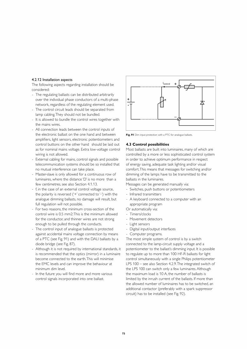
73
4.2.12 Installation aspectsThe following aspects regarding installation should be considered:- The regulating ballasts can be distributed arbitrarily
over the individual phase conductors of a multi-phase network, regardless of the regulating element used.
- The control circuit leads should be separated from lamp cabling. They should not be bundled.
- It is allowed to bundle the control wires together with the mains wires.
- All connection leads between the control inputs of the electronic ballast on the one hand and between amplifiers, light sensors, electronic potentiometers and control buttons on the other hand should be laid out as for nominal mains voltage. Extra low-voltage control wiring is not allowed.
- External cabling for mains, control signals and possible telecommunication systems should be so installed that no mutual interference can take place.
- Master-slave is only allowed for a continuous row of luminaires, where the distance ‘D’ is no more than a few centimetres, see also Section 4.1.13.
- f, in the case of an external control voltage source, the polarity is reversed (‘+’ connected to ‘-‘) with the analogue dimming ballasts, no damage will result, but full regulation will not possible.
- For two reasons, the minimum cross-section of the control wire is 0.5 mm2: This is the minimum allowed for the conductor, and thinner wires are not strong enough to be pulled through the conducts.
- The control input of analogue ballasts is protected against accidental mains voltage connection by means of a PTC (see Fig. 91) and with the DALI ballasts by a diode bridge (see Fig. 87).
- Although it is not required by international standards, it is recommended that the optics (mirror) in a luminaire become connected to the earth. This will minimise the EMC levels and can improve the behaviour at minimum dim level.
- In the future you will find more and more various control signals incorporated into one ballast.
+
–
+-
Icontrol
Fig. 91 Dim input protection with a PTC for analogue ballasts.
4.3 Control possibilitiesMost ballasts are built into luminaires, many of which are controlled by a more or less sophisticated control system in order to achieve optimum performance in respect of energy saving, adequate task lighting and/or visual comfort. This means that messages for switching and/or dimming of the lamps have to be transmitted to the ballasts in the luminaires.Messages can be generated manually via:- Switches, push buttons or potentiometers- Infrared transmitters- A keyboard connected to a computer with an
appropriate programOr automatically via:- Timers/clocks- Movement detectors- Light sensors- Digital input/output interfaces- Computer programs.The most simple system of control is by a switch connected to the lamp-circuit supply voltage and a potentiometer to the ballast’s dimming input. It is possible to regulate up to more than 100 HF-R ballasts for light control simultaneously with a single Philips potentiometer LPS 100 – see also Section 4.2.9. The integrated switch of the LPS 100 can switch only a few luminaires. Although the maximum load is 10 A, the number of ballasts is limited by the inrush current of the ballasts. If more than the allowed number of luminaires has to be switched, an additional contactor (preferably with a spark suppressor circuit) has to be installed (see Fig. 92).

74
NL
-
HFRballast
NL
-+
HFRballast
L1
L2
L3
N
C
C
LPS 100
to lamps
to lamps
- + L1 L2 L3 N
HFR luminaire
HFR luminaire
to otherHFR luminaires
+
4321
Fig. 92 Manual HF regulation.
In many cases, however, manual operation is not sufficient to meet present-day requirements. The lights often have to be switched according to the presence- or absence- detection of people (using movement detectors), or in response to momentary daylight contribution (using a light sensor). With infrared remote control, a great deal of flexibility is achieved, while installation costs are reduced, as vertical (mains) wiring is made redundant.Using these versatile system components, Philips Lighting can offer optimum, custom-designed control solutions.
The control systems and products can be divided into four main categories:- Luminaire-based solutions: stand-alone control, for
(a part of) a single room- Room-based solutions: TRIOS, ActiLume, MultiDim and
OccuSwitch for active control of stand-alone offices- Lighting Management Systems, such as systems for
complete buildings- General purpose products, such as dimmers,
transmitters, receivers, sensors, push-button interface, manual potentiometers, movement detectors.
For all products and systems there are product data sheets, installation instructions, specification guides and/or handbooks available. These should be studied carefully before designing and installing any of the various control systems. There are also special application courses, which
can be followed on request. This section is not intended to cover all aspects of controls. Consequently, only a brief description of the various products and systems is given below.
4.3.1 Luminaire-based controllersThe switching and/or dimming signals for the ballast are generated by a simple sensor or by a controller, which, together with the sensors employed, is built into the luminaire. The luminaire is connected to the mains supply only. The Philips programme comprises several solutions.
1) LuxSense for HF-R 1-10VThe most simple system for a downlight luminaire: just one component!The LuxSense (see Fig. 93) is a very discreet light sensor that reduces (in combination with a HF Regulating ballast) the light output when the illuminance level of the workplace increases above a pre-defined level. There is no switching function inside the LuxSense.Two clips are available for easy mounting of the component on TLD or TL5/PLL lamps. (Note: the LuxSense cannot be used in combination with TL5HO lamps – too hot!) If TL5 HO lamps have to be used, than the LuxSense has to be mounted on a different location e.g. in the infill panel or somewhere else as long as it is not mounted onto the lamp with the usage of the clip. In the case of TLD, the LuxSense must be mounted at the electrical “cold” side of the lamp, and with TL5 at the labelled end of the lamp, at least 5 cm. from the end cap of the lamp. The “cold” side corresponds to the side of the ballast that allows the longest leads. It also can be clicked to the lamella of the luminaire optic, using a special bracket (provided by the customer). It is connected to the 1-10 V
DC control input of Philips HF-R ballast and can
regulate up to 20 luminaires.
The sensor is optimised for use in applications where 600 lux is installed and 500 lux is required, with an assumed reflection factor of the room of 30 per cent. However, actual circumstances may differ, so to compensate for this, the sensitivity of the sensor can be adjusted manually over a range from 1/3 to 3. Therefore the minimum required reflection factor of the room must be 10 per cent, which is met by most practical conditions.

75
Proper control operation is based on the condition that LuxSense controls at least 80 per cent of the artificial light it ‘sees’. This can be critical in applications including a large amount of indirect light from other luminaires.The LuxSense does not provide a constant lux level, but it does compensate for excess daylight by reducing the artificial light level by approximately 50 per cent of the excess.
ballast
> 70 mm
ballast
ballast
ballast
N L
N L
max. 20 Philips HF-R
white
white/grey
-+
LN
Fig. 93 Light control with Luxsense.
2) ActiLume for HF-R DALI
Fig. 94
1 x push = cell mode1 x push = open plan
Daylight regulation Automatically adapts to the surrounding conditions by maintaining a constant light level by dimming the light to the room’s natural light level.
Occupancy control When the room is vacated for a certain time and no movement is detected, the lights will either switch off in case of a cell, or be dimmed down in case of an open plan.
Personal light It is possible to connect a retractive push-to-make button or to use a simple remote control (On/Off Up/Down) by manual override.
ActiLume is different from any other control systems. Thanks to its 2 channel luminaire based DALI controller working together with the new Philips HF-R TD ballast designed on the successful EII technology.
More information on this system can be found in the “Application guide for ActiLume”.

76
Fig. 95
3) ChronoSense ControllerThe ChronoSense is a device especially intended for integration in an outdoor-type luminaire (street lighting, floodlighting, etc) or for fitting onto a gear tray that is mounted at the bottom of a pole. It is mainly meant for usage in outdoor applications with HID ballasts. More information on the ChronoSense you can find in the application guide for HID lamp control gear and the application notes on this control unit.
4.3.2 Room-based solutions
1) OccuSwitch The OccuSwitch operates entirely stand-alone and does not have an interface to other building systems. The OccuSwitch is available with screw and Wieland contacts. The type LRM 1050/1051 contains a movement detector with a built-in light switch. The LRM 1050 is designed for the automatic switching of any light load for maximum 10A
RMS (2300 VA), in indoor applications only.
The detector has dipswitches that enable the end-user or installer to alter its functionality even after installation.The sensor has a built-in “daylight override” function. This function will prevent the unit from switching on the light when sufficient daylight is present, regardless of the detection of movement. The override function can be enabled/disabled by a dipswitch and adjusted by turning the potentiometer or pushing the button.The sensor has built-in intelligence that adjusts the sensitivity according to the needs of the moment. When
the unit detects that somebody is present, it increases its sensitivity, preventing it from switching so long as that presence continues. When the unit detects that nobody is present (longer period of time), it decreases the sensitivity, preventing the lights from switching on without reason (preventing false triggers).The sensor is optimised for recessed ceiling mounting.The sensor has a clearly defined circular detection pattern with a footprint diameter of seven metres at a mounting height of 2.7 metres (see Fig. 96).The light sensor used has a dynamic range of between 10 and 1000 lux.Two OccuSwitches can be connected in parallel; as, for example, in a long corridor (see Fig. 97).
Presence detection means: - Automatically switch on when movement is detected
and light level is too low- Automatically switch off when after a certain time no
movement is detected (or light level is increased above the set limit)
Absence detection means:- No automatic switching on, but must be done by
infrared or switch- Automatically switch off when after a certain time no
movement is detected (or light level is increased above the set limit)
7 m
m7.2
Fig. 96 Working area:Occuswitch.
L
N
L'LNNPEPE
MLML
L'LNNPEPE
MLML
PE
junction box
L'NPE
L'NPE
Fig. 97 Connection diagram:two Occuswitches in parallel.

77
2 ) TRIOS The switching and dimming signals for one set of luminaires are provided by one addressable TRIOS controller LRC 1020/1025, while type LRC 1010/1015 only provides switching signals. The luminaires are connected to the switched mains supply for 5 A maximum and to the dimming control signal of 1-10 V
DC of the HF-R ballasts. Several sensors can be
connected to one controller. TRIOS controllers can function independently of each other with their own set of sensors (Fig. 102). The set of sensors can be shared by a maximum of five controllers in order to control five different sets of luminaires (channels). Channel address setting is obtained with an infrared-programming transmitter. A channel is a group of luminaires that identically switch and dim together. Looking at the end result, a channel looks like a hard-wired circuit.
TRIOS
IR IR
LN
LN
mains
switched mains
dim voltage+-+-
LN
+-
Fig. 98 Wiring diagram:TRIOS controller with sensors.
Four pre-defined lighting situations (presets) are possible, while the lights can be switched from multiple points, and levels can be adjusted, stored and recalled with the four-preset transmitter. This system is mainly used in single or open-plan offices, reception areas, corridors and staircases.The controller is available in two versions: the installer box version, which can be placed above a ceiling, and a DIN-rail version, for mounting in an installation cabinet.
3) MultiDimMultiDim is Multi Master Dimming System based on the DALI protocol. It’s a very flexible system that consists of:- Various button modules that can be mounted into a
wall box- A multisensor- An IR remote control- DALI power supplies- Mains voltage dimmers- Relay module- A mini input unit to which you can connect any type of
switch- A software kitIt goes way to far to explain everything of this system in this booklet. A separate manual is available (MultiDim Installation and Design Manual) where it is all explained. Furthermore there is a second manual especially on the software (MultiDim User Software Manual) explaining everything you need to know to be able to use the software kit. Both manuals and a demo version of the software are available on the Internet at the download section of the dimming website (www.dimming.philips.com). The demo version of the software can also be used to update your current full software version to the latest state of the art.
4.3.3 Lighting Management Systems (for complete buildings)
Building Management Systems are sophisticated lighting-management system. It is a control system for local and building-wide control, an integral part of the building management concept using one network; often integrated with other building services such as heating, ventilation, air-conditioning, window blinds, access, etc. These systems mostly consist of a network of intelligent components that communicate with each other over a bus. These kind of systems often use higher communication languages such as LonWorks®, EIB®, etc.A wide range of devices can generate messages that can be used in these kind of systems. They send the information to an intelligent controller (often a computer) via a bus cable. It is way out of our scope to describe in depth all kind of available systems. If more information on Building Management systems is needed, please be referred to the manufacturers of these systems.
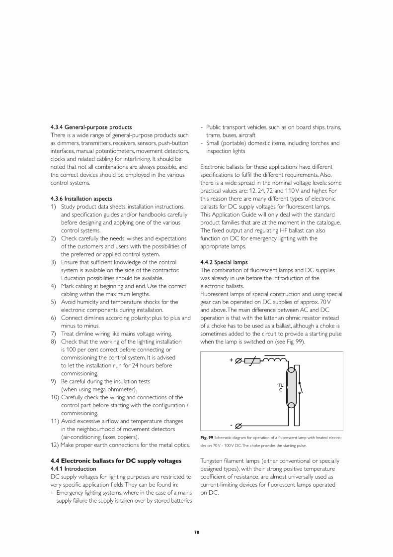
78
4.3.4 General-purpose productsThere is a wide range of general-purpose products such as dimmers, transmitters, receivers, sensors, push-button interfaces, manual potentiometers, movement detectors, clocks and related cabling for interlinking. It should be noted that not all combinations are always possible, and the correct devices should be employed in the various control systems.
4.3.6 Installation aspects1) Study product data sheets, installation instructions,
and specification guides and/or handbooks carefully before designing and applying one of the various control systems.
2) Check carefully the needs, wishes and expectations of the customers and users with the possibilities of the preferred or applied control system.
3) Ensure that sufficient knowledge of the control system is available on the side of the contractor. Education possibilities should be available.
4) Mark cabling at beginning and end. Use the correct cabling within the maximum lengths.
5) Avoid humidity and temperature shocks for the electronic components during installation.
6) Connect dimlines according polarity: plus to plus and minus to minus.
7) Treat dimline wiring like mains voltage wiring.8) Check that the working of the lighting installation
is 100 per cent correct before connecting or commissioning the control system. It is advised to let the installation run for 24 hours before commissioning.
9) Be careful during the insulation tests (when using mega ohmmeter).
10) Carefully check the wiring and connections of the control part before starting with the configuration / commissioning.
11) Avoid excessive airflow and temperature changes in the neighbourhood of movement detectors (air-conditioning, faxes, copiers).
12) Make proper earth connections for the metal optics.
4.4 Electronic ballasts for DC supply voltages4.4.1 Introduction DC supply voltages for lighting purposes are restricted to very specific application fields. They can be found in:- Emergency lighting systems, where in the case of a mains
supply failure the supply is taken over by stored batteries
- Public transport vehicles, such as on board ships, trains, trams, buses, aircraft
- Small (portable) domestic items, including torches and inspection lights
Electronic ballasts for these applications have different specifications to fulfil the different requirements. Also, there is a wide spread in the nominal voltage levels: some practical values are: 12, 24, 72 and 110 V and higher. For this reason there are many different types of electronic ballasts for DC supply voltages for fluorescent lamps.This Application Guide will only deal with the standard product families that are at the moment in the catalogue. The fixed output and regulating HF ballast can also function on DC for emergency lighting with the appropriate lamps.
4.4.2 Special lampsThe combination of fluorescent lamps and DC supplies was already in use before the introduction of the electronic ballasts.Fluorescent lamps of special construction and using special gear can be operated on DC supplies of approx. 70 V and above. The main difference between AC and DC operation is that with the latter an ohmic resistor instead of a choke has to be used as a ballast, although a choke is sometimes added to the circuit to provide a starting pulse when the lamp is switched on (see Fig. 99).
+
-
‘TL’C
Fig. 99 Schematic diagram for operation of a fluorescent lamp with heated electro-
des on 70 V - 100 V DC.The choke provides the starting pulse.
Tungsten filament lamps (either conventional or specially designed types), with their strong positive temperature coefficient of resistance, are almost universally used as current-limiting devices for fluorescent lamps operated on DC.

79
For supply voltages not exceeding 100 V the electrodes are sometimes preheated. Generally speaking, however, DC lamps are of the cold-start type. To facilitate ignition, auxiliary electrodes in the form of internal conductive strips are normally employed. Two strips are always needed, one connected to each main electrode, for the strip can only serve as the anode. If the supply voltage is higher than 200 V, two or more lamps are often connected in series and started one after the other using an electric relay (see Fig. 100).
+
-
‘TL’R
‘TL’R
Fig. 100 Twin-lamp sequence-start circuit for operation on 220 V DC.
A typical problem, which only arises with DC operation, is that of electro-phoresis. During operation, the mercury in the discharge migrates from the positive to the negative electrode. The result is that a dark zone spreads from the positive electrode, which produces a rapid fall-off in light output. To prevent this from happening, the polarity of the lamp must be reversed at regular periods, e.g. every four hours.
After the introduction of the HF ballasts for DC supplies, the systems described above became less popular.
4.4.3 Emergency lighting: definitions and standardsEmergency lighting is lighting that is designed to come into operation when the normal lighting fails. It is split up into the segments shown:
Fig. 101
Standby lighting is defined as that part of the emergency lighting system that enables normal activities to continue or to be terminated safely, e.g. lighting in the control room of a petrochemical factory to enable the operator to shut down the process safely. It depends very much on what normal activities are taking place as to the requirements that have to be set for good standby lighting, so there are no general standards for this segment.Emergency escape lighting is defined as that part of the emergency lighting that provides illumination for the safety of people leaving an area or attempting to terminate a dangerous process before vacating an area. Harmonised European standards have been developed, or are in development, for the three parts:- Escape-route lighting is defined as that part of the
emergency escape lighting that is provided to ensure that the means of escape can be effectively and safely used when the building is occupied.
- Anti-panic (open) area lighting is defined as that part of the emergency escape lighting that is provided to avoid panic and provide illumination to allow people to reach a place where an escape route can be identified.
- High-risk task-area lighting is defined as that part of the emergency escape lighting that provides illumination for the safety of people involved in a potentially dangerous process or situation, and that enables proper shut-down procedures to be completed for the safety of the operator and other occupants of the premises. Standby lighting can also function as high-risk task area lighting.
The VDE 0108-100 is the standard to which most of the ballast manufacturers refer. When reading this standard it is referring to the European standard EN 50172 which is a collection of various standards concerning safety for elevators, central power systems, automatic test systems for batteries, lighting, engine driven generators and electrical installations in buildings. All these chapters refer again to specific standards for the mentioned items. For Lighting this specific standard is the IEC 60598-2-22.
This European standard (IEC 60598-2-22) covers the following aspects: minimum illuminance, response time, duration, colour rendering, luminous intensity, and sighting of luminaires and safety signs. For electronic ballasts the following items are of the most important.

80
High Risk Task
Area Lighting
Any Other Area
50% of rated lumen output < 5 seconds
Full rated lumen output < 0.25 seconds < 60 seconds
Colour rendering index Ra > 40 R
a > 40
Duration Duration of risk > 1 hour
Abstract from IEC 60598-2-22 par. 22.16
There are basically two types of emergency lighting systems:1) Maintained emergency lighting, in which all
emergency lamps are in operation at all times when normal or emergency lighting is required.
2) Non-maintained emergency lighting, in which all the emergency lighting lamps are in operation only when the supply to the normal lighting fails.
Luminaires can be divided into:- Centrally supplied emergency luminaires for
maintained or non-maintained operation. These are energised from a central emergency power system not contained within the luminaire.
- Self-contained emergency luminaires for maintained or non-maintained operation. Here all the elements, such as battery, lamp, control unit and test and monitoring facilities, where provided, are contained inside the luminaire or at a distance of not more than 1 m from it (decentralised).
- Combined emergency luminaires, which contain at least two lamps, at least one of which is energised from the emergency lighting supply and the other from the normal lighting supply. A combined emergency luminaire is either maintained or non-maintained.
Recommendations and standards for decentralised emergency lighting state minimum lighting levels and minimum burning times, but no voltage restrictions. For central emergency lighting, however, there are various regulations, which differ from country to country. Commonly used are the IEC 60598-2-22 and VDE 0108.- Stable burning must be realised for a mains voltage
range from 0.80 Vnom
to 1.15 Vnom
.- Ignition and re-ignition must be possible between
0.90 Vnom
and 1.15 Vnom
.
A second requirement for emergency lighting is that the switchover time from normal to emergency operation or back is limited, depending on the nature of the space
(room) and the activities in that room. For high-risk task area lighting a maximum response time of 0.25 seconds is prescribed in the harmonised European standards. For all other areas the response time must be less than 5 seconds.
The decentralised system is the most reliable, as the individual lamps can go on functioning even during a fire or when the mains cable is destroyed.
4.4.4 Emergency lighting systems
Central1) See Fig. 102a. Here the normal and emergency supplies
and circuitry are separated and the lamp connections are switched by the changeover switch in the luminaire. The normal circuit can contain conventional or HF ballasts; the emergency circuit can have special ballasts. There is no special Philips solution.
lamp
AC supply
DC emergency supply
B
T
transistor ballast
normal 230V ballast,conventional or HF
107a
Fig. 102a Normal and emergency supplies and circuitry are separated;change-over
switch in the luminaire.
2) See Fig. 102b. Here there is a central changeover switch and the luminaire contains only the normal HF ballast circuit. This circuit is the least safe of all circuits, but also the cheapest one.
lamp
AC supply
DC emergency supply
HFballast
107b
Fig. 102b With central change-over switch and one HF ballast.
Decentralised3) See Fig. 102c. Here the lamp is continuously being
powered by an HF converter, which receives energy via the normal mains supply or from the continuously loaded battery pack. Should the mains power fail, the

81
battery can supply the energy necessary for the required time of operation. The HF converter can be a special DC low-voltage ballast.
In normal operation the lamp usually has to deliver 100 per cent light output all the time. Therefore the transformer in the charge unit becomes rather large for higher wattage lamps. This is the reason that this circuit is not widely used for permanent (maintained) lighting.
But this system can be used for non-maintained operation: the lamp only functions for the specified time when the mains supply fails.
HFconverter lampAC
DC
DC HF AC
battery
AC supply
107c
Fig. 102c Lamp powered by an HF converter,receiving energy from a battery pack.
4) See Fig. 102d. Here the emergency circuit is connected in parallel to the normal mains voltage circuit. This is the most widely used system. By means of a changeover switch in the luminaire the lamp is powered either by the emergency circuit or by the mains supply circuit (maintained).
In the emergency situation the lamp can be powered by less energy than in the normal situation, indicated by the so-called ballast lumen factor. The ballast lumen factor is the ratio of the luminous flux from the lamp when operated on the emergency ballast to that produced on the reference ballast. The percentage depends greatly on the type of lamp and batteries used.
battery
HFconverter
lamp
B
AC supply
ACDC 107d
Fig. 102d Emergency circuit parallel to the mains circuit.
5) See Fig. 102e. Here the standard HF ballast is used in combination with a transformer, charger and battery. Due to the high DC voltage, necessary for the HF ballast (typically 280 V), this system is rarely used.
AC supplyHF
ballast lamp
transformer battery
280V DCACDC 107e
Fig. 102e Standard HF ballast used in combination with a transformer,charger and
battery.
Restrictions for switchingSwitching over from the normal situation to the emergency situation normally causes no problems. When switching back from emergency to normal operation, care should be taken for the proper ignition of the lamp. In the case of conventional ballast circuits it is not allowed to employ glow-switch starters (see IEC60598-2-22 par 22.6.1), so electronic starters are to be used. These starters have, like the HF ballasts, predefined ignition characteristics. In order to ensure reliable ignition, the changeover switch has to fulfil certain restrictions.
From Figs 102a to 102e we can distinguish three different types of switching:
- Switching the input voltage of the HF ballast from AC to DC or vice versa (Figs 102b and 102e).
If there is no input voltage for more than a few milliseconds (10 to 35 ms, depending on the ballast type), the ballasts are reset and the lamps extinguish. This means that the lamps have to start again when the input voltage is restored. If the changeover switch reacts within these few milliseconds, the lamps continue burning. But in most cases the switchover time is longer and then the warm start ballasts cannot fulfil the requirement of the maximum switchover time of 0.25 s (if necessary).
As the contacts of the switch or relays have to be suitable for a DC voltage of 300 V and for the inrush currents, special switchgear is necessary.
- Restoring the mains supply after an emergency or after the emergency test procedure (Figs 102a and 102d).
The lamps will only burn on the AC supply when the switchover switch is in the up position. If it is not in that position, the HF ballast or electronic starter will ‘see’ no lamp and so the ignition process will stop after a few seconds. It will restart again when the changeover switch is put in the up position. To avoid possible

82
ignition problems, it is recommended to let the lamp function on the emergency circuit for at least 3 seconds after the restoration of the mains supply before switching to the AC circuit.
- Lamp changeover from emergency to normal AC circuit and vice versa.
Switching the lamp from one circuit to the other can be done by switching all the lamp terminals with a
4-pole relay. The circuit diagram depends on the converter and
ballast used. Due to the great variation in converter and ballast circuits, no general circuit diagram can be given. In case a certain converter has to be combined with a Philips ballast, the most optimum circuit diagram of a emergency unit in combination with a Philips HF ballast are these so called 4 pole inverters that also switch the mains power of the HF ballast (see also Fig 103 for a 1 lamp ballast situation and Fig 103 for a 2 lamp situation).
Fig. 103. One lamp circuit
Fig. 104 Two lamp circuit
The switch over sequence from normal operation to emergency operation should go as follows:
- Normal operation.- Mains drops away.- Emergency unit switches the mains from the HF ballast.- The emergency unit takes over the lamp by
disconnecting all 4 connections (poles) of the lamp from the ballast and to it’s own electronic circuit.
- The emergency unit ignites and runs the lamp.
The switching back to normal operation should than again go in reverse order:- The emergency unit is running the lamp.- The mains is coming back.- The emergency unit switches back the to the
HF ballast.- The mains is connected to the HF ballast.
The switch S1 is the test switch to test the system. The emergency unit will respond as if the mains is dropping away and coming back.
4.4.5 The standard and regulating HF ballast with standard lamps
The Philips HF ballast can be used on a DC voltage for emergency lighting. This is possible because it contains a diode bridge circuit, which transforms the customary AC voltage into a DC voltage. The up-converter than transforms it into a stable higher voltage of about 410V giving 100 per cent light output at 230 V DC. Since there is a DC current supplied there will be no harmonic distortion.As the lamp side of the ballast is functioning similar to the normal AC operation, all lamp-related information of Sections 4.1 and 4.2 are applicable and normal lifetime and failure rate of the gear is guaranteed when continuous operation on DC. Very low DC voltages (below the tolerances for safety) can influence the lifetime of the ballast.For a continuous DC application, an external fuse should be used in the luminaire. This is because the fuse(s) used inside the ballasts are not rated for these kind of applications.
For the HF ballast two DC voltage ranges are specified. From the table below it can be seen that for a nominal emergency supply voltage of approx. 230 V the requirements can be fulfilled.

83
For universal use, the lamps have to be (re-) ignited within 0.25 seconds of applying the restored mains voltage. This is not possible with the warm-start versions HF-P and HF-R.
Various HF ballasts with their DC voltage range and re-ignition time
HF ballast Required voltage DC range Ignition
Guaranteed ignition Stable burning < 0.25 sec
HF-B 198 - 254 V 176 – 254 V Yes
HF-R 198 - 254 V 176 – 254 V No
HF-P 198 - 254 V 176 – 254 V No
All ballasts start within 2 seconds and can be employed in all areas except for the high-risk task area. For High risk task areas only the HF-Basic can be used.

84
5 Electromagnetic lamp control gear
5.1 Ballasts5.1.1 Main ballast functionsIn Section 2.1 of this Guide, General aspects – Main ballast functions, the main functions of ballasts have been described. The term ‘ballasts’ is generally reserved for current-limiting devices, including resistors, choke coils and (autoleak) transformers. Other items of auxiliary equipment are compensating capacitors, filter coils and starters or ignitors. Some systems use an additional series capacitor for stabilisation. With all these components all the control functions that are necessary for the operation of standard fluorescent lamps can be carried out.Special arrangements such sequence start, constant wattage and dimming circuits will not be described in this Guide. Such circuits are being replaced by the modern high-frequency (HF) systems.
5.1.2 StabilisationIn Section 3.2, Stabilisation, the need for current stabilisation in fluorescent lamps has been described, resulting in the following two formulae: I
lamp = (V
mains - V
lamp) / Z
ballast
and: Plamp
= Vlamp
. Ilamp
. αlamp
where Ilamp
= the current through the lamp V
mains = the mains voltage
Vlamp
= the voltage across the lamp Z
ballast = the impedance of the ballast
Plamp
= the power of the lamp α
lamp = a constant called the lamp factor
From these formulae it can be concluded that the power of the lamp (and therefore the light output) is influenced by:- the lamp voltage V
lamp, which in turn is highly dependent
on the operating temperature (see Section 5.3.12: Ambient and operating temperatures) and on the lamp current, according to the negative lamp characteristic (see Section 3.2: Stabilisation).
- the lamp current Ilamp
, which is dependent on the mains voltage (see Section 5.3.13: Effects of mains voltage fluctuations), the lamp voltage and the linearity of the ballast impedance.
In order to avoid undesirable variations in light output as a consequence of mains-voltage fluctuations, the lamp voltage must be not more than approximately half the value of the mains voltage (100 to 130 V), and the impedance should be as linear as possible.
5.1.3 Ignition and re-ignitionIn Section 3.3, Lamps, Ignition, the need for ignition of a fluorescent lamp has been described.In the case of electromagnetic control gear, a combination of preheating and a high ignition peak is obtained by using a normal choke ballast and a preheat starter or an electronic ignitor.
Energy is supplied to the discharge in the form of electrons. The lamp current, just like the mains voltage, is sinusoidal, with a frequency of 50 or 60 Hz. If the energy flow is zero (at lamp current reversal), the lamp stops burning and in theory would have to be re-ignited.This could be done by supplying additional energy to the electrodes via a higher lamp voltage, the way it is done when initially starting the lamp. But from the moment the lamp has reached its stationary condition, the lamp voltage is constant. And yet, in practice, the lamp does not extinguish at current reversal. Why not?The phase shift introduced by the inductive element of the ballast ensures that the mains voltage is not zero at that moment. Because of the inductive properties of choke coil ballasts a phase shift occurs between the mains voltage and the lamp current (see Fig. 105).
V, A
t
A
Vm
Il
Vl
pag
ϕ
Fig. 105 Phase shift between supply voltage and lamp current (and lamp voltage)
in a discharge lamp with an inductive ballast.In the case shown,the supply voltage is
sufficiently to re-ignite the lamp after every current reversal.

85
So, at the moment of current reversal, the lamp voltage would be equal to the mains voltage, since the voltage over the ballast is zero. The difference (gap) between the mains voltage and the average lamp voltage as a consequence of the phase shift ensures proper re-ignition of the lamp at the moment the current passes the point of reversal (zero-point A in figure).
5.1.4 Types of ballasts1 Resistor ballastsCurrent limitation by means of resistor ballasts is a very uneconomic form of current limitation, because in the resistor electrical energy is dissipated in the form of heat. Nevertheless, until the advent of electronic circuitry, use of a series resistor was the only way of stabilising fluorescent lamps operated on DC, for example the ‘TL’R lamp (see Fig. 106). For stable operation on a resistor ballast, it is necessary that the supply voltage be at least twice the lamp voltage under operating conditions. This means that the ballast will dissipate 50 per cent of the power. A considerable improvement in efficiency can, however, be achieved by using a resistor with a very pronounced positive temperature characteristic (an ordinary or specially constructed incandescent lamp serves well for this purpose). A temperature-dependent resistor compensates for variations in the lamp current resulting from variations in the mains voltage, which means that the no-load voltage need be no more than 25 to 30 per cent higher than the lamp voltage. This is also the proportion of the power dissipated by the ballast compared to the total circuit power.
+
-
‘TL’ R
Fig. 106 Schematic diagram of a fluorescent lamp operated on a resistor ballast in
a DC circuit.
2 Capacitor ballastsA capacitor used as a ballast causes only very little losses, but cannot be used by itself, as this would give rise to very high peaks in the lamp current wave-form at each half cycle. Only at very high frequencies can a capacitor serve satisfactorily as a ballast.
3 Inductive ballasts or chokesChoke coils are frequently used as current limiting devices in gas-discharge lamp circuits (see Fig. 107). They cause somewhat higher losses than a capacitor, but produce far less distortion in the lamp current at 50 Hz. Moreover, in combination with a switch starter, they can be made to produce the high voltage pulse needed to ignite the lamp.
I b
Il
La
B Vl
Vm
+
-
+ - + -
0
S
Fig. 107 Schematic diagram of a fluorescent lamp operated on a choke ballast in an
AC starter circuit.
In practice, a choke ballast consists of a large number of windings of copper wire on a laminated iron core. It operates on the self-inductance principle. The impedance of such a ballast must be chosen in accordance with the mains supply voltage and frequency, the lamp type and the voltage of the lamp, to ensure that the lamp current is at the correct value. In other words, each type of lamp requires for each supply voltage its own choke as a ballast with a specific impedance setting.Heat losses, occurring through the ohmic resistance of the windings and hysteresis in the core, much depend upon the mechanical construction of the ballast and the diameter of the copper wire.The right ballast for a given lamp and supply voltage should be chosen by consulting documentation and/or ballast markings.The Philips standard range of ballasts is for supply voltages of 220/230/240 V and for the mains frequency of 50/60 Hz. The most important value for stabilisation is the ballast impedance. It is expressed as the voltage-current ratio in ohm (Ω) and is defined for a certain mains voltage, mains frequency and calibration current (normally the nominal lamp current).
Chokes can be used for virtually all discharge lamps, provided that one condition is fulfilled: the mains voltage should be about twice the arc voltage of the lamp. If the mains voltage is too low, another type of circuit should be used, such as the autoleak or constant-wattage circuits.

86
The advantages of a choke coil are:- the wattage losses are low in comparison to those of a
resistor,- it is a simple circuit: the ballast is connected in series
with the lamp.
Disadvantages of a choke coil are:- the current in a lamp with choke circuit exhibits a
phase shift with respect to the applied voltage, the current lagging behind the voltage, resulting in a power factor of approx. 0.5 inductive (see also Section 5.3.4: Power factor correction).
- a high starting current: in inductive circuits the starting current is about 1.5 times the rated current.
- sensitivity to mains voltage fluctuations: variations in the mains voltage cause variations in the current through the lamp.
5.1.5 Ballast specification and markingThere are two ways of selecting the right ballast for a certain lamp or comparing various ballasts:1) the ballast marking,2) the manufacturer’s documentation.As all ballasts have to comply with the norms IEC 60921 (Performance) and IEC 61347-2-8 (Safety), some data has to be marked on the ballast and other data can be mentioned in the documentation.
On the ballast can be found:- Marks of origin, such as the manufacturer’s name or
trade mark, model or reference number, country of origin, production date code,
- Rated supply voltage and frequency, nominal ballast current(s),
- Type(s) of lamp with rated wattage,- Type(s) of ignitor with wiring diagram and peak voltage
if this exceeds 1500 V,- t
w and Δt (see Section 5.1.6),
- Maximum cross-section of mains or lamp cable; e.g. 4 ® means 4 mm2,
- Symbols of the officially recognised certification institutes, such as ENEC for safety and performance and CE marking for safety, EMC and EEI index (where CE is mandatory to be able to sell within the European Community)
- In the case of an independent ballast: the symbol ; an independent ballast is a ballast that is intended to be mounted separately outside a luminaire and without
any additional enclosure,- A symbol like if there are mounting restrictions,- F-marking if the ballast fulfils the IEC F-requirements;
that means it is suitable to be mounted directly on normally flammable surfaces,
- TS, P-marking or if the ballast is thermally protected (* = thermo-switch temperature in degrees Celsius),
- Indication of terminals: L for single phase, N for neutral, for protective earth (PE) and for functional
earth,- Rated voltage, capacitance and tolerance of separate
series and/or parallel capacitor.
In the documentation can be found:- Weight,- Overall and mounting dimensions,- Power factor (λ, P.F. or cos ϕ),- Compensating capacitor value and voltage
for λ = 0.85 or 0.9,- Mains current nominal and during running-up, both
with and without power factor correction,- Watt losses (normally in cold condition),- Description of version, e.g. open impregnated, ‘plastic’
encapsulated, potted or compound filled.
This information suffices to find the right ballast for a certain application. Additional information can be obtained on request or can be found in special application notes. Philips ballasts are designed for use with IEC standardised fluorescent lamps and can be found on the WEB site catalogue.
5.1.6 Maximum coil temperature tw and ΔTA ballast, like most electrical components, generates heat due to its ohmic resistance and magnetic losses. Each component has a maximum temperature that may not be exceeded. For ballasts it is the temperature of the choke coil during operation that is important. The maximum permissible coil temperature t
w is marked on
the ballast. Coil insulating material, in combination with lacquer, encapsulation material, etc., is chosen in such a way that below that temperature the life specified for the ballast is achieved. A t
w value of 1300C is usual nowadays
with a coil insulating class F (1500C) or class H (1800C).Under standard conditions, an average ballast life of ten years may be expected in the case of continuous operation at a coil temperature of t
w 0C. As a rule
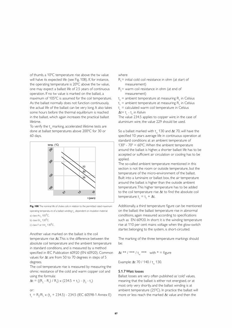
87
of thumb, a 100C temperature rise above the tw value will halve its expected life (see Fig. 108). If, for instance, the operating temperature is 200C above the tw value, one may expect a ballast life of 2.5 years of continuous operation. If no tw value is marked on the ballast, a maximum of 1050C is assumed for the coil temperature.As the ballast normally does not function continuously, the actual life of the ballast can be very long. It also takes some hours before the thermal equilibrium is reached in the ballast, which again increases the practical ballast lifetime.To verify the t
w marking, accelerated lifetime tests are
done at ballast temperatures above 2000C for 30 or 60 days.
052
002
051
0011,0 0,1 01
temp. (°C)
t (years)
(c)
(b)
(a)
Fig. 108 The nominal life of choke coils in relation to the permitted rated maximum
operating temperatu-re of a ballast winding tw ,dependent on insulation material:
a) class A:tw 1050C,
b) class E:tw 1200C,
c) class F or H:tw 1300C.
Another value marked on the ballast is the coil temperature rise Δt. This is the difference between the absolute coil temperature and the ambient temperature in standard conditions, and is measured by a method specified in IEC Publication 60920 (EN 60920). Common values for Δt are from 50 to 70 degrees in steps of 5 degrees.The coil temperature rise is measured by measuring the ohmic resistance of the cold and warm copper coil and using the formula:Δt = (R
2 - R
1) / R
1 x (234.5 + t
1) - (t
2 - t
1)
or : tc = R
2/R
1 x (t
1 + 234.5) - 234.5 (IEC 60598-1 Annex E)
whereR
1 = initial cold coil resistance in ohm (at start of
measurement)R
2 = warm coil resistance in ohm (at end of
measurement)t2 = ambient temperature at measuring R
2 in Celsius
t1 = ambient temperature at measuring R
1 in Celsius
tc = calculated warm coil temperature in Celsius
Δt= tc - t
2 in Kelvin
The value 234.5 applies to copper wire; in the case of aluminium wire, the value 229 should be used.
So a ballast marked with tw 130 and Δt 70, will have the
specified 10 years average life in continuous operation at standard conditions at an ambient temperature of 1300 - 700 = 600C. When the ambient temperature around the ballast is higher, a shorter ballast life has to be accepted or sufficient air circulation or cooling has to be applied.The so-called ambient temperature mentioned in this section is not the room or outside temperature, but the temperature of the micro-environment of the ballast. Built into a luminaire or ballast box, the air temperature around the ballast is higher than the outside ambient temperature. This higher temperature has to be added to the coil temperature rise Δt to find the absolute coil temperature: t
c = t
2 + Δt.
Additionally, a third temperature figure can be mentioned on the ballast: the ballast temperature rise in abnormal conditions, again measured according to specifications such as EN 60920. In short: it is the winding temperature rise at 110 per cent mains voltage when the glow-switch starter, belonging to the system, is short-circuited.
The marking of the three temperature markings should be:
Δt ** / *** / tw *** with * = figure
Example: Δt 70 / 140 / tw 130.
5.1.7 Watt lossesBallast losses are very often published as ‘cold’ values, meaning that the ballast is either not energised, or at most only very shortly, and the ballast winding is at ambient temperature (250C). In practice the ballast will more or less reach the marked Δt value and then the

88
copper resistance is approx. 25 per cent higher than in the ‘cold’ situation. Therefore the ‘warm’ losses in practice will be very often 10 to 30 per cent higher than the published values.Since in some applications the power consumption is of prime importance, there are low-loss ballasts for the major lamp types ‘TL’D 18, 36 and 58 W (BTA xx). To from a class C ballast to a class B2 or to from B2 to B1, there are different possibilities. One of the, is to increase the number of lamellas. An other possibility is to use a better quality of steel for the lamellas. A third option is to use different type of wiring. Of course a combination of these 3 options can also be used to get the most optimum situation. To do so, this will result in lower ballast temperatures and 25 to 30 per cent less ballast watt losses. Hence: As can be read in chapter 2.4, the class C ballasts are banned in the EU as of November 2005.
5.2 Starters5.2.1 Main starter functionsFluorescent lamps do not ignite at mains voltage. To ignite the lamps, a starter is employed to preheat the lamp electrodes and to give a peak voltage high enough to initiate the discharge.So in fact there is only one basic function for a starter : to deliver the ignition voltage to start the discharge in a fluorescent lamp in a proper way. After ignition, the starter has to stop producing ignition peaks. This can be obtained by sensing the lamp voltage or lamp current and/or by a timer function.
5.2.2 Starter typesThere are two types of fluorescent lamp starters: 1 Glow-switch startersThe glow-switch starter consists of one or two bimetallic electrodes enclosed in a glass container filled with a noble gas. The starter is connected in parallel to the lamp in such a way that the preheat current can run through the lamp electrodes when the starter is closed (Fig. 109). At the moment of switching on the mains voltage, the total mains voltage is across the open glow-switch starter. This results in a glow discharge starting between the bimetallic electrodes of the starter. The glow discharge causes a temperature increase in these bimetallic electrodes, resulting in the closure of the electrodes of the starter. During this closure, the lamp electrodes are
preheated by the short-circuit current of the ballast. After closure, the temperature of the starter electrodes decreases and the starter re-opens. At the moment of re-opening, the current through the ballast is interrupted, causing a peak voltage across the lamp electrodes high enough for lamp ignition. This peak voltage depends on the inductance of the choke, the level of the short- circuit current and the speed of the opening of the glow-switch electrodes. Expressed in an equation:
0
0
0
Fig. 109 Working principle of a glow-discharge starter circuit..
1. The heat from the discharge in the starter bulb causes the bimetallic electrodes
to bend together.
2. When the bimetallic electrodes make contact,a current starts to flow through the
circuit that is sufficient for preheating the electrodes of the fluorescent lamp.
3. The bimetallic electrodes cool down and open again,causing a voltage peak,which
ignites the fluorescent lamp.
Peak voltage: Vpeak
= L dI/dt
The minimum specified peak voltage depends on the type of glow-switch starter, and is between 800 and 900 V.

89
If the lamp electrodes are not hot enough or the peak voltage is not high enough, the glow-switch starter will resume the whole starting process again until the lamp ignites. If the lamp will not ignite (end of life), the starter will continue producing peaks (flickering) until the mains voltage is switched off, one or two electrodes of the lamp break or until the electrodes of the glow-switch starter stick together. In the latter case the short-circuit current is continuously running through the lamp electrodes, which can be seen at the glowing lamp ends.
Once the lamp is properly ignited, the lamp voltage is too low for a glow discharge between the starter electrodes. So these electrodes stay ‘cool’ and in the open position.A small capacitor across the starter electrodes prevents radio-interference of the lamp.
There are two types of glow-switch starters, specified for certain mains voltages and/or lamp wattages (S2 and the S10). There is also a resettable glow-switch starters the SiS10. This starter switches off after a certain time should the lamp fail to ignite and has to be reset manually by a push-button. Switching the mains supply does not reactivate a switched-off resettable starter.
2 Electronic startersIn principle the electronic starter or ignitor works in the same manner as the glow-switch starter. The difference is that the switching does not come from bimetallic electrodes, but from a triac.The electronic circuit in the starter gives a well defined preheat time (1.7 sec) for the lamp electrodes and, after the preheat, a well-defined peak voltage, which ensures optimum lamp ignition. The heart of the electronic starter is a customised integrated circuit, containing the intelligence of the product. It makes the starter switch off after seven unsuccessful ignition attempts, so it is called ‘flicker free’.The electronic starter also contains an over-heating detection by means of a PTC resistor, to switch itself off should it become too hot (e.g. with a short-circuited ballast). This second stop function resets after approximately 4 minutes.The electronic starter extends the lamp lifetime by up to 25 per cent on account of the well-defined preheat time. The exact digital timing makes the electronic starter independent of mains voltage fluctuations.In the Philips programme there are two electronic
starters both in the canister of the glow-switch starters (two-pin types S2-E and S10-E Perform version).
5.2.3 LifetimeThe lifetime of fluorescent lamp starters is expressed in terms of the number of switching cycles.At present, glow-switch starters have a lifetime of 10 000 cycles or more, while the electronic starters have a lifetime of 100 000 cycles or more, while the resettable version can do at least 60 000 cycles.
5.3 Systems5.3.1 ComponentsA customer is primarily interested in finding a solution to his lighting requirements. Basically, he needs two things, both of which must completely meet his specifications: a design and components. To make sure that the installation works properly under all circumstances, the right components must be chosen and selected in combination with each other.In principle the following components are required in a lighting installation:- Lamps- Lamp holders- Luminaires - Gear (ballasts, starters)- Compensating capacitors- Cabling- Fusing and switching devices- Filter coils (if necessary)- Dimming equipment (if possible and required)
Information about lamps can be found in the lamp documentation, where also the type of lampholder or lamp cap is mentioned. Be sure to use the appropriate lampholder, as there are many different types. Lamps with different wattages are in principle not interchangeable in a given circuit, even though they may have the same lamp cap and fit into the same lampholder. In some lamp types the glow-switch starter is incorporated in the lamp base (e.g. 2-pin version PL).

90
The luminaire documentation contains information as to which lamp types can be used. When installing other than specified types, electrical, thermal or lighting problems may arise. The luminaire documentation will also state whether or not the gear is incorporated in the luminaire and what the cable entries and connections are.
The gear documentation contains information on the electrical terminals and the electrical wiring diagrams. The value and the voltage range of capacitors is also mentioned here.
The remaining system-related components and subjects mentioned above will be described in the following sections.
5.3.2 CapacitorsTwo types of capacitors are found in fluorescent lamp circuits. One type is the parallel compensating capacitor for power factor improvement, connected across the mains 230V / 50 Hz or 60 Hz, between live and neutral. In installations with fluorescent lamps of more than 25 W, capacitors are necessary for power factor correction, as the power factor of an inductively stabilised circuit is only approximately 0.5. The parallel capacitor does not influence the lamp behaviour. It normally has a capacitance tolerance of +/- 10%.The second type of capacitor is the series capacitor, which also determines the lamp current. Series capacitors are used in capacitive or duo circuits, see Section 3.4: Power factor correction. In these circuits the voltage across the capacitor is higher than the mains voltage, usually more than 400 V. So normally they should be marked with 450 V, with a capacitance tolerance of +/- 4%.
In the relevant ballast documentation figures can be found for the capacitor value in microfarad (µF) and capacitor voltage needed for a certain combination of lamp and supply voltage to achieve a power factor of > 0.9.Every user can in fact create his own solution for obtaining the necessary capacitance.
To do things well, certain design aspects have to be considered:- First of all, capacitors for discharge lamp circuits
have to fulfil the requirements as specified in IEC publications 61048 and 61049. Moreover, they have to fulfil the Philips Standard ULN-D 1580 (Compensating
Capacitors for discharge lamps circuits) in which (among other aspects) the use of PCB (chlorinated biphenyl) is forbidden.
- It is recommended that capacitors that have approval marks such as VDE, KEMA, DEMKO, CE or ENEC, be used.
- Normally every lamp circuit is compensated by its own capacitor. Only in some special cases can group or central compensation for a number of lamp circuits prove a better solution.
- In the case of failure of the parallel capacitor (open or short-circuited), the lamp behaviour is not affected. Regular control of the mains currents and/or power factor (λ or cos ϕ) is advisable.
- In the case of failure of the series capacitor, the lamp behaviour is immediately affected. This type of capacitor must create an open circuit in case of failure, so that the lamp will extinguish.
- The lifetime of capacitors depends on the capacitor voltage and capacitor case temperature. Therefore capacitors with the correct voltage marking (parallel 250 V with a maximum tolerance on capacitance of +/- 10% or series 450 V with a maximum tolerance on capacitance of +/- 4 %) and within the specified temperature range (normally -250C to +850C or +1000C) should be used. Used within the specifications, capacitors with the VDE marking will have a lifetime equal to that of ballasts: 30 000 hours or 10 years.
- If a specified parallel capacitance value is not available, the next higher value can be used, provided that the value is not more than 20 per cent above specification.

91
Two general types of capacitors are currently in use: the wet and the dry type.
The Wet capacitors currently available contain a non-PCB oil and are equipped with internal interrupters to prevent can rupture and result in oil leakage in the event of failure. So a clearance of at least 15 mm above the terminals has to be provided to allow for expansion of the capacitor. In the case of failure, these capacitors will result in an apparent open circuit, which means that in the case of a parallel capacitor the mains current drawn by the circuit approximately doubles. This can cause a fuse to blow or a circuit breaker to open, but will have no further detrimental effect.Used as a series capacitor, the open circuit of the failing capacitor will extinguish the lamp.
Dry, metallised-film capacitors are relatively new to the lighting industry and are not yet available in all ratings for all applications. However, they are rapidly gaining popularity because of their compact size and extreme ease of installation and are, therefore, widely used nowadays. There are basically two families of metallisation material: pure aluminium and zinc. During its lifetime the aluminium type of capacitor gradually loses its capacitance. This type of capacitor is therefore not allowed according to the Philips ULN-D norm.Dry capacitors are more sensitive to voltage peaks than wet capacitors. In critical applications (mains supplies containing peaks, frequent switching, high level of humidity or condensation), the wet capacitor is advisable.
The material of the capacitor enclosure can be of metal or plastics. In both cases a safety device must be included that opens the electrical circuit at over-pressure inside the capacitor. For metal can capacitors this requirement is no problem (expansion rills), but with a plastics cap this is more difficult to achieve. It can result in the enclosure not being fully watertight. It is therefore advisable to employ metal-can capacitors in humid or aggressive environments.There must be at least 2 cm free space for the expansion rills to expand when built into a luminaire or cabinet.Capacitors for lighting applications must have a discharge resistor connected across the terminals to ensure that the capacitor voltage is less than 50 V within 1 minute after switching off the mains power. In special cases
the voltage level must be 35 V within 1 second, see IEC 60598-8.2.7.
5.3.3 Filter coilsIn some countries, including Belgium, The Netherlands and France, the electricity distribution network is used for transmitting messages. This falls under the responsibility of the local energy supply authority.Signals are sent over the electricity supply network for a number of purposes: to switch road lighting, to call up fire brigades and the police, to switch night-tariff kWh-meters, and so on. It is important, therefore, that this signalling system is not disturbed, which may occur when parallel power factor correction capacitors for lamp circuits are employed. Capacitors present a low reactance to the 200-1600 Hz signals employed for signalling, with the result that these are in danger of being short-circuited in a capacitive circuit. To avoid this, a coil must be connected in series with the capacitor connected parallel to the mains. This filter coil, as it is termed, presents a reactance that increases with rising signal frequency. The coil reactance is therefore so chosen as to balance out the reactance of the capacitor at 200 Hz (the resonance frequency, see Fig. 110), although types with a different resonance frequency can be found on the market.
impedance (Z)
frequency(Hz)
capacitive inductive
2
4
6
8012
2
4
68013
011
2 4 6 8 012 2 4 6 8 01
3 2 4 6 8 014
011
impedance of filtercoilZ = ωL
impedance of coiland capacitorZ = | ωL -1 |impedance of capacitorZ = 1___
ωC
___ωC
Fig. 110 Impedance of a filter coil,a capacitor and a coil/capacitor combination as a
function of frequency.

92
For currents with a frequency of 50 Hz, the circuit is predominantly capacitive, which is necessary for power factor correction. Above 200 Hz the circuit becomes predominantly inductive, which is necessary for the blocking of audio-frequency signals. At 200 Hz the impedance is formed only by the ohmic resistance, mainly of the filter coil.As can be seen from the graph, the filter coil is effective for audio signals of 300 Hz and higher, because then the impedance of the coil/capacitor combination is higher than the impedance of the capacitor on its own. Filter coils should not be used when the audio signals are 300 Hz or lower.When the audio-frequency is high (say >1200 Hz), a physically smaller filter coil can be employed by fixing the resonance frequency not at 200 Hz but at, say, 400 Hz.
There are other advantages to be gained from employing filter coils. The parallel capacitor can cause troublesome switching phenomena to occur, which can give rise to very large current surges. Although these surges are of only very short duration (a few milliseconds), they are nevertheless sufficient to cause switching relays to stick or circuit breakers to trip. The filter coil serves to prevent this problem by damping the very short, high-amplitude pulses in the current.The type of filter coil needed depends on the value of the capacitor used. So in fact every capacitor needs its own filter coil. In some cases, however, it is possible to group the capacitors and match them with the corresponding filter coil. For example: two capacitors of 4 µF connected in parallel can be placed in series with one filter coil for 8 µF capacitor (see Fig. 111).
L
N
L
N
2 coils for 4 µFcapacitors
2 x 4 µF = 1 coil for 8 µF capacitor
2 x 4 µFcapacitors
Fig. 111 Different ways of grouping capacitors to match them with the corresponding
filter coil.
The value of a coil is normally given in mH but in this case, on the coil is the value of the capacitor printed with which this coil should be in series. According to the Philips nomenclature you could have a filter coil by the name of FC 10/230 where FC stands for Filter Coil, 10 stands for suitable for capacitors with a value of 10 µF and 230 stands for the nominal mains voltage, which is in this case 230V.Although the voltage across the filter coils is rather low (approx. 14 to 20 V), the filter coils have to be regarded as ballasts, as they are directly connected to the mains. They also cause some additional watt losses.The voltage across the parallel compensating capacitor will increase by between 5 and 7 per cent as a result of adding a filter coil.The amount of third and fifth harmonics in the mains current will increase in cases where the mains supply voltage is disturbed by these harmonics, when applying a filter coil. The total impedance for the combination of capacitor and filter coil is lower than the impedance of the capacitor alone for these frequencies (see Section 5.3.9: Harmonic distortion, and Fig. 110).Central filter coil systems also exist where a filter system in the supply system blocks the applied signalling frequencies.
5.3.4 Power factor correction Circuits with gas-discharge lamps are stabilised with inductive ballasts and compensated for a good power factor with a parallel compensating capacitor (mono-compensation, Fig. 112).Without the capacitor the inductive ballast causes a phase shift of the current, which is lagging behind the applied voltage.
B
CLa
L
N
Fig. 112 Power factor correction with a parallel compensating capacitor.

93
This can be seen in Fig. 113, which shows the lamp current I
l, the lamp voltage V
l (both in phase with each
other), and the sinusoidal form of the mains voltage Vm.
Vm
Vl
I
ϕ
Fig. 113 Lamp current (Il),lamp voltage (V
l) and mains voltage (V
m).
The power factor of the circuit can be calculated by dividing the total wattage by the product of mains voltage and current. Expressed in an equation:
P.F. = (Wl + W
b) / (V
m x I
m) (1)
Without the parallel compensating capacitor, the power factor of a gas-discharge circuit is approximately 0.5.For the fundamentals of the voltages and current a so-called vector diagram can be made (see Fig. 114).
Vb
1.1 Vm
Vm
0.9 Vm
VlIl
ϕ
Fig. 114 Example of a vector diagram showing lamp voltage and lamp current in phase.
Lamp voltage and lamp current are in phase and the voltage across the ballast is leading the current by 90 degrees. The vectorial sum of lamp voltage and ballast voltage gives the mains voltage. Now we see that
cos ϕ = Vl / V
m, which is less accurate than (1).
In any case, the energy supply authority has to deliver an apparent power of V
m x I
l to the system on which the
distribution network must be based (thickness of cabling, transformers etc.).The energy meter only records the in-phase component V
m x I
l x cos ϕ, so the supply authority does not get paid
for the so-called 'blind' part: Il x sin ϕ x V
m (Fig. 115).
Vb Vm
VlIlIl nis ϕ
Il cos ϕ
ϕ
Fig. 115 Uncompensated circuit with lamp current and mains voltage out of phase.
It is for this reason that the supply authority insists on compensation of the phase shift. Where in general the ‘unadjusted’ power factor is about 0.50, it has to be compensated to a minimum of 0.85, or even 0.90. This is achieved by adding a capacitor across the mains. In contrast to an inductive ballast, the capacitor current is leading the capacitor voltage (which is the mains voltage) by 90 degrees. So the capacitor current has the opposite direction of I
l x sin ϕ (see Fig. 116).
Vb Vm
VlIlIl ni
s ϕ
Ipac
Il cos ϕ
ϕ
Fig. 116 Compensated circuit.

94
Maximum compensation is achieved when the current through the capacitor I
c = I
l x sin ϕ; the power factor is
then 1. This is purely theoretical, as the vector diagram is only valid for the fundamentals of the currents. Due to distortion in the lamp current (see Section 5.3.9: Harmonic distortion), the maximum practical power factor is between 0.95 and 0.98. This explains the difference between power factor and cos ϕ. The power factor is the result of the quotient of the actual wattage and the product of mains voltage and mains current, including the harmonics, and can be calculated as follows:
Power factor (P.F.) = total wattage / (mains voltage x mains current)
The angle ϕ is the phase shift angle between mains voltage and mains current and can be found and calculated by means of the vector diagram. This is only valid for the fundamentals and does not take into account the harmonics.
The same analogy is valid for the lamp: there is practically no phase shift between lamp voltage and lamp current: both are zero at the same time. So the phase angle α is zero and cos α = 1.The product of lamp voltage and lamp current does not equal the lamp wattage; the difference is called lamp factor :
Lamp factor = lamp wattage / (lamp voltage x lamp current)
and has a value between 0.8 and 0.9. For the same lamp type, the lamp factor is higher for higher wattages – which is the same for the lamp efficacy.Typical capacitor values for this parallel compensation (also sometimes called mono-compensation) for a 50 Hz mains are 4.5 µF for a 36 or 40 W fluorescent lamp and 6.5 µF for a 58 W or 65 W lamp.
A second method of compensation is the so-called lead-lag or duo-circuit. This is employed for pairs of lamps, as for example in two-lamp luminaires. Here the capacitor is placed in series with one of the ballasts (see Fig. 117).
0
‘TL’1
‘TL’2S S
L2
L1
C
Fig. 117 Duo-circuit with the capacitor placed in series with one of the ballasts.
The series capacitor has an impedance that is twice the normal ballast impedance, resulting in a power factor of approximately 0.5 capacitive (leading) for one branch. Together with the power factor of 0.5 inductive (lagging) for the other branch, the total power factor of the two branches is approximately 0.95. In most cases the power factor is lagging (inductive load), but in some duo circuits the power factor is leading (capacitive load).In that case sufficient additional inductive load should be added to avoid problems in the installation.
With a normal 230 V supply, the voltage across the capacitor is about 400 V. To fulfil all relevant requirements, the tolerance on the value of the capacitor has to be within +/- 4 %. The nominal value of the capacitance is dependent upon the mains supply voltage, the applied ballast impedance, and the lamp wattage. Typical values are 3.4 µF for a 36 W and 5.3 µF for a 58 W lamp.Compared with the mono-compensation, the advantages of this method of compensation are:- Only one capacitor is required for two lamps, instead
of two- The capacitive branch is less sensitive to supply-voltage
deviations, as it has a constant current characteristic- In the case of actadis signals (see Section 5.3.3: Filter
coils), these signals are not influenced, so no filter coil is needed
Disadvantages of duo-compensation are:- Series capacitors are more expensive than parallel
capacitors- The lamp power and so the light output from the
capacitive branch is slightly higher than that from the inductive branch

95
In some countries, practically all multi-lamp luminaires have built-in duo-circuits for each pair of lamps (also called a ‘dual-lamp’ or ‘lead-lag’ circuit). Mono-compensation, on the other hand, is generally left to the installer, although there are also single-lamp luminaires available with the compensation built in.
The capacitive circuit has a so-called ‘constant-current characteristic’. This can be explained by the non-linearity of the inductive ballast. Suppose that the impedance of the ballast is 400 Ohm, which varies say 10 per cent when the ballast voltage changes 10 per cent (see Fig. 118).
081081
081081
081081
081081
081081
081
061
041
021
001
08
06
04
02
001002
003004
005006
007008
0090001
Z1 = 165 = 360 Ω
Z1 = 150 = 400 Ω
Z1 = 135 = 440 Ω
____0,458
____0,375
____0,307
1
2
3
V ballast (V)
I ballast (mA)
Fig. 118 Voltage/current characteristic of an inductive ballast (example).
With the inductive ballast, the resulting (lamp) current at 90 per cent mains voltage will be lower:A: as result of the lower mains voltageB: as result of the higher impedance
With the capacitive ballast combination, the resulting impedance of inductive ballast and capacitor is reacting in just the opposite way: at lower mains voltage the total impedance is also lower. This results in a nearly constant current.
Mains voltage
Circuit
90 % 100 % 110 %
Ind. Cap. Ind. Cap. Ind. Cap.
Z ballast (Ω) 440 440 400 400 360 360
Z capacitor (Ω) 800 800 800
Z result (Ω) 440 360 400 400 360 440
The behaviour of the inductive and capacitive branch of a duo-circuit is therefore different at mains voltage deviations and deviations of the ambient temperature. This can be seen rather well in a duo-luminaire.
5.3.5 Series connection of lampsUnder certain conditions it is possible to operate two lamps in series on a common ballast (see Fig. 119). A prerequisite for such operation is that the sum of the operating voltages of the lamps is not higher than approximately 60 per cent of the supply voltage. This means that two lamps, each with an arc voltage of no more than 65 volt, can be connected in series via one common ballast to the 220/240 V mains. This restricts the maximum lamp length to 600 mm (2 ft), or the lamp power to 18/20 W (26 or 38 mm diameter lamps only).The series circuit can be compensated in the normal way by using a parallel or series capacitor.
0
‘TL’1
‘TL’2
S
S
Fig. 119 Tandem circuit with two lamps in series on a common ballast.
Parallel connection of two lamps on a common ballast is impossible because of the negative characteristic of the fluorescent lamp. All the current would flow through the lamp with the lower arc voltage. Moreover, once the first lamp is ignited the lamp voltage is too low for the ignitor of the second lamp to ignite this lamp.
5.3.6 Neutral interruption and resonance Normally each lamp circuit has its own compensating capacitor. In this way every luminaire can be switched separately without influencing the power factor. For the same reason, lamp circuits based on phase-neutral (230 V), are compensated with capacitors connected between each of the phases and neutral.
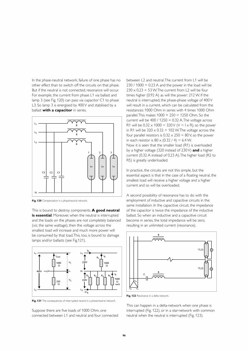
96
In the phase-neutral network, failure of one phase has no other effect than to switch off the circuits on that phase. But if the neutral is not connected, resonance will occur. For example, the current from phase L1 via ballast and lamp 3 (see Fig. 120) can pass via capacitor C1 to phase L3. So lamp 3 is energised by 400 V and stabilised by a ballast with a capacitor in series.
LaLaLa
B
B
B
N
1 2 3
C3 C2 C1
L1
L2
L3
Fig. 120 Compensation in a phase/neutral network.
This is bound to destroy components. A good neutral is essential. Moreover, when the neutral is interrupted and the loads on the phases are not completely balanced (viz. the same wattage), then the voltage across the smallest load will increase and much more power will be consumed by that load. This, too, is bound to damage lamps and/or ballasts (see Fig.121).
L1
L2
Itotal
1000
250
400V
V1
V2
L1
N
L2
IR
IR
4 IR
IR
1000
1000
each
230V
230V
R1
R2 R3 R4 R5
Fig. 121 The consequences of interrupted neutral in a phase/neutral network.
Suppose there are five loads of 1000 Ohm, one connected between L1 and neutral and four connected
between L2 and neutral. The current from L1 will be 230 / 1000 = 0.23 A and the power in the load will be 230 x 0.23 = 53 W. The current from L2 will be four times higher (0.92 A) as will the power: 212 W. If the neutral is interrupted, the phase-phase voltage of 400 V will result in a current, which can be calculated from the resistances: 1000 Ohm in series with 4 times 1000 Ohm parallel. This makes 1000 + 250 = 1250 Ohm. So the current will be 400 / 1250 = 0.32 A. The voltage across R1 will be 0.32 x 1000 = 320 V (V = I x R), so the power in R1 will be 320 x 0.32 = 102 W. The voltage across the four parallel resistors is 0.32 x 250 = 80 V, so the power in each resistor is 80 x (0.32 / 4) = 6.4 W.Now it is seen that the smaller load (R1) is overloaded by a higher voltage (320 instead of 230 V) and a higher current (0.32 A instead of 0.23 A). The higher load (R2 to R5) is greatly underloaded.
In practice, the circuits are not this simple, but the essential aspect is that in the case of a floating neutral, the smallest load will receive a higher voltage and a higher current and so will be overloaded.
A second possibility of resonance has to do with the employment of inductive and capacitive circuits in the same installation. In the capacitive circuit, the impedance of the capacitor is twice the impedance of the inductive ballast. So when an inductive and a capacitive circuit become in series, the total impedance will be zero, resulting in an unlimited current (resonance).
B
B
‘TL’D
‘TL’D
C
S
S
Fig. 122 Resonance in a delta network.
This can happen in a delta-network when one phase is interrupted (Fig. 122), or in a star-network with common neutral when the neutral is interrupted (Fig. 123).

97
N
S
S
B
B
‘TL’D
‘TL’D
C
Fig. 123 Resonance in a star network.
esonance problems can be prevented with special switchgear. If the neutral in a star-network or a phase in the delta-network fails, such special gear switches off the overall supply for the lighting installation.
5.3.7 Electrical diagrams
B
C
L
N
La
V
Fig. 124
1) One lamp, inductive or compensated with electronic or glow-switch starter ‘TL’, ‘TL’D, ‘TL’E, ‘TL’U, PL-L, PL-T, PL-T(S)(C) 4-pins
B
C
L
NLa
La
V
V
Fig. 125
2) Two lamps, inductive or compensated with electronic or glow-switch starter ‘TL’, ‘TL’D, PL-L
B
CLa
L
N
Fig. 126
3) One lamp, inductive or compensated without starter PL-S, PL-C, PL-T (starter incorporated)
B
CLa
La
L
N
Fig. 127
4) Two lamps, inductive or compensated without starter PL-S, PL-C (starter incorporated)
B
BCL
N
La
V
La
V
Fig. 128
5) Duo-circuit, two lamps, with electronic or glow-switch starter ‘TL’D, ‘TL’E, ‘TL’U, PL-L
B
B
C
L
N
La
VLa
VV
V
La
La
Fig. 129
6) Duo-circuit, four lamps, with electronic or glow-switch starter ‘TL’D, PL-L

98
5.3.8 Mains voltage interruptions and short-circuitingFor various reasons, the supply voltage can be subject to deviations; therefore a certain degree of deviation from the rated value has been taken into account everywhere. With gas-discharge lamps, deviations of up to +/- 10 per cent of the rated supply voltage normally have no detrimental effects.
Apart from such ‘normal’ variations, in practice four possible uncontrolled effects can be distinguished:1) Short-circuit of the mains voltage2) A dip in the power supply voltage3) Interruption in the power supply current4) Increase in power supply voltageThese phenomena can occur during a thunderstorm, when switching from one power supply source to another, or when connecting heavy loads to the mains, and are usually of very short duration. This is a good thing too, since a single dip of 10 milliseconds (half a cycle), or even less, can have a significant influence: the lamp will extinguish.As the fluorescent lamp re-ignites in only a few seconds or less, these phenomena are not really a problem in practice (see also Section 4.1.15: Effects of mains voltage fluctuations).
5.3.9 Harmonic distortionAll gas-discharge lamps stabilised by copper/iron ballasts have harmonics in the lamp current. The first reason for this is that the lamp voltage (= the voltage across the discharge tube) is approximately a square wave of changing polarity every half cycle (see Fig. 130).
Vm
Vl
I
Fig. 130 Square waveform of lamp voltage.
This is graphically represented as a square wave voltage, made up by Fourier analysis as the fundamental sine wave of the mains supply and a large number of odd harmonics (see Fig. 131).
1
3
57
9
0
π 2π
U
Fig. 131 Lamp voltage waveform constructed by the odd harmonics from one to
nine, according to the formula: f(t) = 4U/π(sinωt + 1/3sin3ωt + 1/5sin5ωt + ....).
The voltage across the ballast is the vectorial difference between the supply voltage and the lamp voltage, so the harmonics of the lamp appear in the ballast voltage. As the ballast determines the current, there will be only odd harmonics in the lamp current. Even harmonics are not present.
The second reason for the presence of harmonics in the lamp current is the hysteresis of the ballast coil. With the aid of the relationship between ballast voltage and ballast current (B-H curve of the ballast coil, see Fig. 132), the resulting current can be found for any ballast voltage.
H,i
H,i
t
B,Φ,V B,Φ,V
Fig. 132 Hysteresis curve of a typical copper-iron ballast..

99
Even with a pure sine-wave ballast voltage there will be some harmonics in the ballast current, but this effect is small compared with the harmonics caused by the lamp.The impedance of the coil becomes higher for higher frequencies, so in practice only odd harmonics up to the seventh are of any importance for the lamp current.Practical values as a percentage of the fundamental for most inductively-stabilised discharge lamps are:fundamental: 100 %third harmonic: 10 %fifth harmonic: 3 %seventh harmonic: 2 %ninth and higher harmonics: 1 % or lowerWhen the supply voltage contains harmonics, these values can change somewhat, but the ballast coil prevents dramatic increases.
International requirements have been laid down for the proportion of the harmonics in supply mains currents. According to IEC 61000-3-2, for lighting equipment having an input power >25 W the maximum percentage of harmonics for the input current are:second harmonic: 2 %third harmonic: 30 x P.F. %, where P.F. =
power factor of the circuitfifth harmonic: 10 %seventh harmonic: 7 %ninth harmonic: 5 %11 < n < 39 3 %
All Philips inductively-compensated lighting circuits (P.F. = 0.5) comply with this standard. The capacitive branch of a duo-circuit has higher values, but as a whole the duo-circuit meets this standard.
To obtain a good power factor (0.9) of the system with gas-discharge lamps, parallel capacitors are mostly used. The effective mains current will then be nearly half, so the percentage harmonics automatically will be doubled. Again, there will be no problems in fulfilling the requirements. A capacitor, however, has lower impedance for higher frequencies and therefore the capacitor current is very sensitive to harmonics in the supply voltage.
The quality of the supply source influences the amount of higher harmonics in the mains voltage and consequently in the mains current. The lamp is only responsible for roughly 20 per cent third harmonics in the current of
the phase-conductor. When the amount of seventh or higher harmonics is too high, a solution could be found in connecting filter coils in series with the capacitors. But adding the filter coils will result in higher third and fifth harmonics, because the total impedance for the combination of capacitor and filter coil is lower for these frequencies than the impedance of only the capacitor (see Fig. 110 in Section 5.3.3). So a filter coil does not help to suppress third and fifth harmonics.
The presence of harmonics has consequences for the mains wiring.For the various wiring diagrams, calculations of the currents and harmonics can be made. Lighting installations connected to three-phase supplies having a common neutral conductor, need particular attention.The neutral conductor carries a current equal to the vector sum of the currents through the three phase conductors. In a well-balanced system (equal effective phase-currents), the fundamental frequencies of these currents add up to zero, but the third, ninth and fifteenth harmonics are in phase and thus amplify each other (see Fig. 133).
R S T
(b)
(a)
0 06 021081
042003
063
Fig. 133 Fundamental and third harmonic in a three-phase mains.R,S and T are the
fundamentals in the three conductors.Owing to the phase shift,this results in a zero
current in the neutral lead.
a) Third harmonic of a phase,
b) Third harmonic of all three phases in the neutral lead.The individual currents
reinforce each other.

100
The neutral will therefore carry at least about 3 x 20 = 60 per cent of the phase current. For this reason the neutral conductor must have the same cross-section as each of the phase conductors.In the case of a poorly designed system, the current in the neutral can be higher than one of the phase currents.In the case of a supply voltage containing some distortion, the current through the neutral can also grow rapidly due to higher capacitor currents. This can be of great importance when the supply voltage is coming from a separate generator.
5.3.10 Electromagnetic interferenceDischarge lamps do not only emit visible radiation, they also generate energy in the radio-frequency spectrum. This can cause disturbance in the operation of electronic equipment such as computer keyboards, television or radio receivers, hence the name radio interference.As the luminaires in which the lamps are used should fulfil international requirements such as EN 55015 (CISPR 15), the radio interference in practice is sufficiently low to have no harmful effects on the surrounding. Products with the mark ADD SYMBOL conform to VDE 875 part 1. The generation of radio-interference radiation is normally caused by lamp electrode oscillations. Such radiation has a broadband character, usually with frequencies of up to 1500 kHz, so FM radio receivers and television receivers are not affected.The electromagnetic waves, which can have effects on the AM broadcast band, are propagated in two ways: either directly through the mains into the receiver, or via radiation picked up by the aerial.The latter form of interference will seldom occur with discharge lamps, as the ballast will suppress the broadband signals. The radiation produced by the lamp will nearly always remain below the threshold value at which interference takes place, especially where the lamp is at some distance from the aerial (more than, say, 1 metre).The supply cables can emit interference radiation when they are not buried in the ground or laid in earthed steel piping, which is the best screening against interference. However, it sometimes happens that an interference signal reaches the receiver by way of its mains input. The interference signal can consist of high-frequency harmonics of the mains frequency or high-amplitude pulses. The former are generally adequately suppressed in the ballast. Experience has shown that interference may
be caused by fluorescent luminaires with external ballast where the radiation from the supply wires is picked up by telephone or other cables. If external ballasts are used, the supply cables between ballast and luminaire should be as short as possible. Ballast coils should be split into two adjacent parts (split-windings type of ballast). In case of Class I luminaires, the supply wires should be shielded and this shielding should be properly connected to the earth connection.In practically all other cases it will be necessary to connect a delta filter between the mains supply and the input to the lamp circuit. Fig. 134 shows an example of a delta filter used for suppressing radio interference. The apex of the filter must be connected to the ground. More complicated filters are used in three-phase networks.
L
N
5 nF
5 nF
0.2 mF
Fig. 134 Delta filter used for suppressing radio interference.
Avoid earth looping (all earth terminals to one point), and create the maximum possible distance between audio and lighting cabling. If audio and lighting cables have to cross each other, they should do so at right angles. In sensitive applications, screening of cabling is necessary.
5.3.11 LifetimeWhen used within the specifications, the various circuit components will last for many years with no more failures than approximately 1 per cent per year (except for lamps and glow-switch starters).Most of the time, failures in the gear components are caused by external circumstances, such as wrong wiring or connections, short-circuiting, extreme heat or humidity, mains voltage peaks, poor maintenance, etcetera.For example, capacitors for lighting installations with the VDE approval according to VDE 0560 must achieve a lifetime of 30 000 hours at their indicated voltage

101
(250 or 450 V) and their maximum case temperature (850 or 1000C). Higher voltages will shorten the capacitor life as follows:
Voltage (times Vmark) 1.15 1.25 1.30 1.35 1.40 1.45 1.50
Approx. Lifetime (h) 8500 4000 2900 2000 1500 1100 780
A failure rate of 5 per cent is then accepted and the capacitance loss must be less than 10 per cent for parallel and 5 per cent for series capacitors.Temperatures above the indicated maximum capacitor-case temperature will halve the lifetime of the capacitor for every 8 degrees increase. Therefore, if there are too many failures with capacitors, the capacitors may be too hot or the applied voltage (momentarily) too high.
For glow-switch starters the number of switching cycles is specified as 10 000 or more. Deviations are caused by the different starting currents of the various lamp types.For electronic starters, the most relevant factor is the permitted ambient temperature or the maximum case temperature t
c. The specified temperature range is from
-400C to + 800C. Exceeding these temperature limits will shorten their lifetime dramatically.
5.3.12 Ambient and operating temperaturesTemperature is of prime importance for the proper functioning of discharge lamps (Fig.155a/b). In general, fluorescent lamps are very sensitive to changes in the ambient temperature (see Section 3.3.6: Effects of temperature).
021
001
08
06
04
02
02 03 04 05 06 07
%
lamp head temp. (˚C)
Il
Pl
Vl
Φ
recommendedtemperature range
Fig. 135a Relative values of luminous flux (Φ),lamp voltage (Vl),lamp current (I
l)
and lamp wattage (Pl) as a function of lamp head temperature,for a PL lamp.
Φ), lamp voltagel ) as a function of
001
08
06
04
02
002- 0 02 04 06
Φ (%)
ambient temp. (˚C)
Fig. 135b Relative values of luminous flux (Φ) as a function of the ambient tempe-
rature and the burning position (PL lamp).
For the total system, the ambient temperature is also of great importance. This is due to the fact that certain minimum and maximum operating temperatures are specified for the various components.
Minimum temperatures
1) LampsSupplied with the nominal voltage, fluorescent lamps will start quite normally at temperatures down to approximately -200C. The minimum allowed temperature depends on lamp type and starting system, which determines the maximum ignition time (ranging from 2 to 20 seconds). The circuitry (leading or lagging) also influences the ignition process. Two lamps in series normally ignite less easily than does one lamp. In the lamp data sheets, the minimum temperature and the resulting ignition time can be found for the various circuits. Below these specified temperatures, smooth ignition cannot be guaranteed.In the table below, the ignition time of a PL-L 24 W lamp (in seconds) is given as an example according to the type of circuitry (lagging or leading), supply voltage (nominal or sub-nominal), type of starter, and ambient temperature.

102
Circuit Voltage
Starter
Lagging
Nominal
Leading
Nominal -8%
Leading
Nominal
Leading
Nominal -8%
Ambient temp. 0C S10 ES08 S10 ES08 S10 ES08 S10 ES08
-30 10 2 * 2 * * * *
-25 7 2 * 2 20 2 * 2
-20 6 2 12 2 8 2 15 2
-15 6 2 12 2 8 2 15 2
-10 6 2 10 2 7 2 14 2
-5 6 2 10 2 7 2 11 2
0 6 2 10 2 7 2 11 2
+5 6 2 9 2 6 2 8 2
* Proper ignition not guaranteed.
Once ignited, the lamp warms up its surroundings and, after run-up, the low ambient temperature has less influence on the electrical performance. Still, the light output varies with the actual hot spot temperature. Capacitive circuits give less light at low temperatures than do inductive circuits due to the constant-current characteristic of the capacitive circuit.
2) GearThe minimum operating temperature for some electronic components and for compensating capacitors is -250C. The capacitance of capacitors, for instance, declines steeply below this temperature. For this reason, gear should be installed at places where the ambient temperature will not fall below -250C.
3) LuminairesIn general, the construction of the luminaires and optics is not affected by low ambient temperatures down to -250C. Of course, plastics parts such as clips are more brittle at low temperatures and should then be handled with care.
Maximum temperatures
1) LampsFor fluorescent lamps the temperature of the glass tube wall is of prime importance, especially with regard to the phosphors employed. It will be clear that the actual lamp temperature very much depends on the luminaire in which the lamps are placed. Lamps must only be used in luminaires that are designed for that particular type of lamp. For some lamp types, absolute maximum temperatures of a specified spot are given (see SL, Fig. 156). With this in mind, also see maximum and ambient temperatures under point 3) Luminaires.
5 mm
warmest regionof the housing
Fig. 136 The maximum recommended ambient temperature at which an SL
lamp can operate is 55 oC.The part of the lamp with the highest temperature is
a 5-mm-wide section around the circumference of the housing.The temperature
measured in this region,on the surface of the housing,is about 150 oC. Exceeding this
temperature can result in reduction of lamp life.
2) Geara) Ballasts
The main ballast temperature parameters tw (maximum
permissible coil temperature) and Δt (coil temperature rise in standard test) are described in Section 5.1.6. Ballasts are normally mounted directly inside a luminaire. The actual ballast coil temperature will in practice depend on the cooling properties of the ballast surroundings, e.g. material of mounting surface, type of fixing, stationary air or ventilation. For this reason it is impossible to predict the actual ballast coil temperature without doing a temperature test under actual operating conditions. Of

103
course, a ballast will normally be cooler when it has lower losses and/or a lower Δt value and/or larger dimensions.Connections to a ballast are in many cases made by means of a terminal block. These terminal blocks have their own temperature limits, usually 1000C to 1200C, which should not be exceeded.
b) Starters
Since they incorporate semiconductors and capacitors, electronic starters have a maximum permissible temperature. This value is marked on the starter and is usually 80 or 900C. In most applications the case temperature of the starter will not exceed this limit, as the starters produce scarcely any heat by themselves. But if the starter is incorporated in the luminaire or placed near the hot ballast, its temperature can rise considerably. It is advisable to mount the starter on the coolest spot possible.
c) Capacitors
Capacitors have a maximum permissible temperature, which is marked on the case and is usually 850C or 1000C. Above this temperature they can break down or lose capacitance. They produce scarcely any heat by themselves and must be placed away from the hot ballast. Additional temperature measures are advisable when the case temperature of the capacitor is unknown and can be critical.
3) Luminaires
Professional luminaires are, like ballasts, designed and constructed to have (under standard conditions) an average lifetime of at least 10 years in continuous operation with the appropriate lamp type.The volume of the luminaire, the choice of materials, the cooling properties, etc., are chosen in such a way that, at an ambient temperature of 250C in indoor applications, no part of the luminaire exceeds its maximum specified temperature. In practice, this ambient temperature limit is sufficient to cope with most applications and non-nominal circumstances, as long as the latter are within the specifications. In cases where the ambient temperature is (momentarily) higher than 300C, the most critical part of the luminaire may exceed its maximum specified temperature. This, of course, shortens lifetime, but to
what extent is in general hard to say. It depends on the part in question (e.g. luminaire housing, mirror optics, cabling, lamp tube, lamp base, etc.).In outdoor applications, a natural air circulation around the luminaire is assumed, which gives a cooling effect of about 100C. The same luminaire with an indoor ambient temperature limit of 250C will, in practice, have an outdoor ambient temperature limit of 350C. If an ambient temperature t
a is given for outdoor luminaires, it refers to
the outdoor situation.
Special lamps, luminaires and electrical circuits have been developed for use in hot, cold, humid or potentially explosive environments.Amalgam lamps – and to a lesser extent also krypton-filled (‘TL’D) lamps – are not susceptible to the drop in light output at high ambient temperatures experienced by normal fluorescents. When normal lamps are operated on inductive ballasts, these may well overheat due to the increase in the lamp current brought about by the higher operating temperature (see Fig. 137).
%
t (˚C)
Iind
IcapPindVind
PcapVcap
Φind
Φcap
021
06
04
02
001
08
02 04 06 08 001
0
Fig. 137 Influence of temperature increase on lamp current (I),lamp voltage
(V),lamp power (P) and luminous flux (Φ) for a 40 W fluorescent lamp on inductive
and capacitive ballasts.
However, where the decrease in light output and luminous efficacy can be tolerated, and provided proper measures are taken to prevent overheating of the circuitry, tube wall temperatures of up to about 900C are acceptable.The use of properly ventilated luminaires will, in most environments, obviate any heat problems. An air stream through the luminaire is an effective way of removing the heat generated by the lamp and ballast.
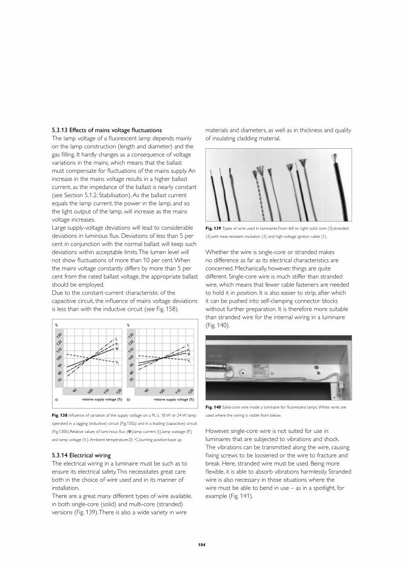
104
5.3.13 Effects of mains voltage fluctuationsThe lamp voltage of a fluorescent lamp depends mainly on the lamp construction (length and diameter) and the gas filling. It hardly changes as a consequence of voltage variations in the mains, which means that the ballast must compensate for fluctuations of the mains supply. An increase in the mains voltage results in a higher ballast current, as the impedance of the ballast is nearly constant (see Section 5.1.2: Stabilisation). As the ballast current equals the lamp current, the power in the lamp, and so the light output of the lamp, will increase as the mains voltage increases.Large supply-voltage deviations will lead to considerable deviations in luminous flux. Deviations of less than 5 per cent in conjunction with the normal ballast will keep such deviations within acceptable limits. The lumen level will not show fluctuations of more than 10 per cent. When the mains voltage constantly differs by more than 5 per cent from the rated ballast voltage, the appropriate ballast should be employed.Due to the constant-current characteristic of the capacitive circuit, the influence of mains voltage deviations is less than with the inductive circuit (see Fig. 158).
03102101100109
08
07
09 001011
021
%
relative supply voltage (%)
IlPl
Vl
Φ
031021011001
09
08
07
09 001011
021
%
b)a) relative supply voltage (%)
IlPl
Vl
Φ
Fig. 138 Influence of variation of the supply voltage on a PL-L 18 W or 24 W lamp
operated in a lagging (inductive) circuit (Fig.130a) and in a leading (capacitive) circuit
(Fig.130b).Relative values of lumi-nous flux (Φ),lamp current (Il),lamp wattage (P
l)
and lamp voltage (Vl). Ambient temperature:25 oC,burning position:base up.
5.3.14 Electrical wiringThe electrical wiring in a luminaire must be such as to ensure its electrical safety. This necessitates great care both in the choice of wire used and in its manner of installation.There are a great many different types of wire available, in both single-core (solid) and multi-core (stranded) versions (Fig. 139). There is also a wide variety in wire
materials and diameters, as well as in thickness and quality of insulating cladding material.
Fig. 139 Types of wire used in luminaires.From left to right: solid core (3),stranded
(3),with heat-resistant insulation (3) and high-voltage ignition cable (1).
Whether the wire is single-core or stranded makes no difference as far as its electrical characteristics are concerned. Mechanically, however, things are quite different. Single-core wire is much stiffer than stranded wire, which means that fewer cable fasteners are needed to hold it in position. It is also easier to strip, after which it can be pushed into self-clamping connector blocks without further preparation. It is therefore more suitable than stranded wire for the internal wiring in a luminaire (Fig. 140).
Fig. 140 Solid-core wire inside a luminaire for fluorescent lamps. White wires are
used where the wiring is visible from below.
However, single-core wire is not suited for use in luminaires that are subjected to vibrations and shock. The vibrations can be transmitted along the wire, causing fixing screws to be loosened or the wire to fracture and break. Here, stranded wire must be used. Being more flexible, it is able to absorb vibrations harmlessly. Stranded wire is also necessary in those situations where the wire must be able to bend in use – as in a spotlight, for example (Fig. 141).

105
Fig. 141 Flexible stranded wire inside the pivoting base of a spotlight.
The diameter (or rather the cross-sectional area) of the wire must be matched to the strength of the current flowing through it. A wire whose cross-sectional area is too small has a resistance that is too high and it will become warm, this will result in heat loss and reducing the efficiency of the luminaire. A minimum nominal cross-sectional area of 0.5 mm2 is laid down in IEC 60598-1, although this may be reduced to 0.4 mm2 in certain cases where space for internal wiring is severely restricted (see IEC 60598-1, Section 5.3.1).
Of particular importance with regard to insulation material and thickness is, of course, its temperature resistance. Here it must be kept in mind that it is not only the temperature of the air in the luminaire that matters, but also that of components with which the insulation may come in contact, such as ballast and lamp holders. The insulation of the wires used must be resistant to all such temperatures, not only under normal conditions of operation, but also in the presence of a fault condition.Not all kind of insulation is suitable for use in luminaires. For example, simple PVC (polyvinyl chloride) insulation is only heat resistant up to 900C. It contains a softener, which can vaporise, making the insulation brittle and therefore it will be prone to be damaged. Moreover, the evaporated softening agent attacks a number of plastics used in the manufacture of luminaire housings. There is, however, an inexpensive PVC insulation that is heat-resistant up to a temperature of 1050C, and which is safe in this respect. Where temperatures in excess of 1050C can arise, yet another kind of PVC insulation is usually employed, one that is resistant up to 1150C.
Where still higher temperatures may be encountered, as in floodlights for example, silicone rubber (1700C to 2000C) and PTFE (polytetrafluorothene) (2500C) insulating materials are available. Extra protection can be obtained by covering the insulation with a glass-fibre sleeve.In order to keep the chances of heat damage to the insulation to a minimum, the wiring run should also be chosen in such a way to avoid as far as possible any ‘hot spots’ in the luminaire, such as ballast or lampholders.The cable fasteners used to hold the wiring in place should allow it some slight freedom of movement, for the insulating covering of wire that is under mechanical strain will have a lower heat resistance than that specified by the manufacturer.
There is an internationally standardised colour coding for electrical wiring, namely that specified by the IEC: brown for live, blue for neutral and yellow/green for earth/ground.The only time when a departure from this colour coding is permissible, is in the case where luminaires have internal wiring that is visible when the unit is in use. A white insulation is then often used so as to blend in with the white of the housing. The proviso here is that the connection block is clearly labelled.
5.3.15 HumIn general, lamps, ignitors, capacitors and even luminaires do not produce any disturbing noise level when correctly used in their application. Sometimes during the starting process some hum or rustling can be noticed, especially with glow-switch starters. If hum is noticeable, it almost always comes from the electromagnetic ballast(s). Anyhow, when used in indoor applications, e.g. shops, the hum level caused by control gear should be as low as possible.
The electric current passing through the coil of a ballast causes a magnetic field, which arranges the disorderly oriented elementary magnetic particles of the ballast iron. So we find in the iron magnetostriction and magnetic poles.The ordering of the elementary magnets causes a certain deformation of the iron (magnetostriction), resulting in the iron expanding in certain directions. This process is repeated every half cycle if alternating current is used and results in a noise of 100 Hz in a 50Hz mains and higher harmonics.

106
The magnetic poles exert forces of attraction in the air gap of the ballast core, also resulting in a noise of 100 Hz and higher harmonics. The generation of these magnetic vibrations can be suppressed to a high degree by means of a suitable design of the ballast. In particular, air gap filling and ballast encapsulation can contribute to low noise levels.But the magnetic field also spreads outside the magnetic core. All magnetic metal parts in the immediate surroundings of the ballast, such as the ballast case, the sheet-steel of the luminaire, etc., are subject to forces in this magnetic field and can cause noise.
To avoid unpleasant ‘humming’ noise, constructions for the ballast mounting, as well as the ballast mounting itself, must be as rigid as possible. The hum will be more pronounced if the ballast is mounted on a resonant surface. Avoid loose metal parts and create distances between ballasts and metal parts.
5.3.16 DimmingDimming can be defined as the reduction of the luminous flux of a lamp, either continuously or in steps, by reducing the operating current. This is not always possible without adversely affecting the performance of the lamp.
L
N
L
N
a)
c) d)
b)
L
N
L
N
Fig. 142 Four basic ways of dimming:
a) by a variable resistor
b) by a variable transformer
c) by a thyristor circuit
d) by frequency regulation.
Basically, dimming is achieved in one of the following ways (see Fig. 142):- By switching a (variable) resistor or inductive coil in
series with the lamp(s)- By running the lamp(s) from a variable transformer- By suppressing the AC waveform of the supply current
during part of the cycle by means of an electronic element (thyristor) – such a device is also called a ‘chopper circuit’
- By increasing the frequency of the supply current of an inductive coil, thereby increasing the impedance of this
Resistors are now rarely used for dimming purposes. They are inefficient and produce a lot of heat.
Variable transformers are appreciated because of their high power handling capacity, but at the same time they are heavy and expensive.
L
N
L
N
BBextracoil
C C
Fig. 143 Dimming with an extra inductive coil in series and by a thyristor.
In the case of fluorescent lamps operated on electromagnetic gear, dimming is mostly achieved by the extra inductive coil in series or by the thyristor circuit (Fig. 143). In both cases only inductive circuits are allowed, and the parallel compensating capacitor must be placed before the dimming device. Capacitive or duo-circuits are not allowed because:- With the extra series impedance, the total impedance
for stabilising would become lower instead of higher - With the thyristor circuit, the moment of current
suppression must be different for the inductive and the capacitive branch due to the phase shift, which is impossible to realise in one and the same device.
During dimming, only the lamp current will decrease. The capacitor current will remain the same. The result is that the power factor will become capacitive and will shift to lower values.

107
Inductive coils, in the form of an extra ballast, are used to reduce the light output of street-lighting lanterns after a certain hour. This is done either by switching the extra ballast in series with the principal one, or by using two ballasts of half the nominal power rating in parallel, switching one off when dimming is required.
Thyristor dimmers are by far the most popular nowadays, because they are small and inexpensive.Dimming to give half the light output is nearly always possible. By using thyristor dimmers, various types of fluorescent lamps can be dimmed down to about 50 per cent of the nominal lamp current, which roughly corresponds to a 50 per cent reduction in light output (so-called ‘top dimming’). For indoor installations, however, top dimming is of limited practical use and at ambient temperatures below 50C krypton-filled lamps, like the Philips ‘TL’D, may become unstable when dimmed.The disadvantage of thyristor dimming where lamp circuits incorporating glow-discharge starters are concerned, is that the dimmed lamp will cause the starter to become conductive. At what degree of dimming this will happen is difficult to predict, but the result is that the starter will make repeated attempts to ignite the lamp. This is the main reason why dimming of fluorescent lamps in a glow-switch starter circuit is discouraged.When dimming to below 50 per cent of the nominal current, the discharge will no longer provide sufficient heat to keep the electrodes at the proper emission temperature, and continuous electrode heating becomes necessary. The heating current must be independent of the lamp current, thus a separate heating transformer will be required. Lamps operated in this mode can be dimmed to give almost zero light output (but not entirely, unless a switch is provided). They can also be started from a dimmed position. These dimming installations almost invariably operate at high frequency to prevent disturbing flicker at low lighting levels.
Frequency regulation is the most widely used technology, and is employed in the Philips HF electronic light regulation ballast. With this ballast the lamp current can be regulated down to about 3 or 1 per cent of the nominal value (depending on the type of dimming ballast). Dimming is here achieved by increasing the frequency of the lamp current.
5.3.17 Stroboscopic effect and striationsFor this subject, see also Section 3.3.10. 1) A fluorescent lamp operating on an alternating current
will exhibit a fluctuating light output. This is because the lamp extinguishes and re-strikes every half cycle of the supply. So this light ripple has a fixed (mains) frequency and can cause the stroboscopic effect. It mainly depends on the phosphors used in the lamp: the use of phosphors exhibiting little or no afterglow may result in more pronounced fluctuations.
˚ ˚ ˚ ˚˚
1 cycle
0 09 081072
063
1 cycle
0 09 081072
063˚ ˚ ˚ ˚ ˚
1 cycle
0 09 081072
063˚ ˚ ˚ ˚ ˚
a)
b)
c)
Fig. 144 Prevention of the stroboscopic effect by using combined inductive and
capacitive circuits (‘lead-lag’ or duocircuit) and by spreading the lighting over the
three phases of the supply.

108
The use of inductive (Fig. 144a) and capacitive circuits together in a duo or ‘lead-lag’ combination reduces the light ripple (Fig. 144b) In an inductive circuit, the lamp current will lag behind the supply voltage by approximately 60 degrees, while in the capacitive circuit the current will lead the voltage by approximately 60 degrees. This means that the light output of a twin-lamp duo-circuit has two components mutually shifted by 120 degrees.
The best solution for preventing the stroboscopic effect is to spread the lighting over the three phases of the supply (Fig. 144c), where the minimum light output of one lamp coincides with high light outputs of the two other lamps.
2) The light ripple can also have an effect on the quality of camera pictures. This phenomenon may become apparent when CCD colour cameras operate in auto-shutter mode and the lighting of the area is predominantly with fluorescent lamps.
The auto-shutter mode is normally selected when cameras are equipped with manual or fixed-iris lenses and the automatic light response is controlled by an electronic shutter system in the camera. The stronger the light to which the camera is exposed, the shorter the shutter time, hence the shorter the light integration time in the sensor. For example, with a shutter time of 1/1000th of a second the light integration of the CCD sensor is only 1 ms. Within the normal CCIR scanning period of 20 ms (50 Hz), the 1/1000th of a second light integration time is just a snapshot in the normal frame-scanning period. In this manner the sensitivity of the camera is reduced.
As described before, the light output of fluorescent lamps varies continuously from minimum (at zero crossing) to maximum during the positive and negative phases of the mains voltage, twice during one mains-voltage cycle. In other words: the fluorescent lamp is flashing 100 times per second. Due to the ‘persistence of vision’ of our eyes, viewing a scene illuminated with ‘TL’ lamps, gives the impression of a white and continuous light output.
At the dip of the light output, the excitation of the fluorescent powders takes place with minimum energy. At this point, the light output is therefore not white, the colour depending on the properties of the non-saturated excitation of the fluorescent powders in the lamp.
As the human eye works as an integrator, this effect cannot be noticed. The light ripple of a TL lamp is illustrated in Fig. 145.
white light
yellowish light
reddish light
momentary light output
non-saturatedphosphors
Fig. 145 Colour shift during the 100 Hz light ripple of a fluorescent lamp.
When the automatic shutter in the camera is switched off, the two light ripples of a ‘TL’ lamp are integrated during the normal 20 ms frame integration time of the sensor and consequently the light impression is white. This is illustrated in Fig. 146.
20 ms
100Hz fluorescentlight ripple
normal shutter time
Fig. 146 The 20 ms frame integration time of a CCD colour camera with the auto-
matic shutter switched off,compared with the 100 Hz fluorescent light ripple.
Using the automatic shutter in sufficiently illuminated scenes, the shutter speed increases and consequently light integration in the sensor takes place during a shorter period of time. Depending on the position where the light integration (snap-shot) takes place with

109
respect to the mains phase (light ripple), it is now possible that a TV frame is shot during the non-saturated excitation of the fluorescent light, see Fig. 147.
light integration
short shutter time
mains lock fase
20 ms
Fig. 147 Using the automatic shutter and with the camera locked to mains
frequency,it is possible to shoot stable and white pictures.
It can be said that the light at this point in time is not white and the light output is less. If the phase of the camera shutter remains constant with respect to the mains phase, the automatic light control and the white-balance circuits in the camera will compensate for these effects and stable pictures will be produced. This situation is obtained by locking the camera frame synchronisation to the mains (mains lock).
When there is no fixed phase relation between the scanning frequency of the camera (free running) and the mains frequency, the camera will take a snapshot of the scene at varying phases of the fluorescent lamp light output. This causes a colour fading to become visible. The extent of the colour fade will depend on the lighting design of the area.
In applications where the scene is illuminated with just one fluorescent lamp or other gas-discharge lamp, stabilised by conventional gear, the colour-fading risk is at its maximum. It is recommended that cameras be locked to mains frequency and the phase of the camera synchronisation be adjusted such that the camera signal output is maximum. If mains lock is not possible in such an application, the lens iris should be closed to the point where the colour fading just disappears. Now the shutter speed is less (full-frame integration), and the additional benefit is that the sensor smear effect is less. This solution cannot be used in applications that need short shutter speeds to suppress movement blur.
In all other cases (combination of inductive and
capacitive circuits, three-phase installation of high-frequency stabilised) this phenomenon will not occur.
3) The movement of the arc on the electrode(s) (flicker) has no fixed frequency and will only become noticeable in exceptional cases. It depends on several factors, including lamp position, supply voltage, temperature, age of the lamp (electrode), and also the lamp current waveform (peak factor).
4) Striations are noticeable as a pattern of more or less bright regions in the long discharge tube of fluorescent lamps. The pattern can move through the discharge tube. It can appear when the lamp is cold or when the lamp is dimmed down to too low a level.
In the past there have been several investigations to find the cause for these striations. Unfortunately there has never been a conclusive answer to the question. The most probable theory is that it originates due to local discontinuities in the discharge inside the lamp. They can be enhanced by the system (lamp / ballast combination) causing resonance’s. By introducing asymmetry in the system, for example put a small DC current through the lamp, these striations can be reduced in such a way that they fall outside the application area, meaning that if they first arose at +5°C they now arise at a much lower temperature. This phenomena also can be influenced by the gas pressure inside the lamp, the kind of gas used, the current density inside the lamp and the temperature. This phenomena can occur with HF ballasts as well as with 50Hz (conventional) ballasts. Fortumately this phenomena has no negative side effects on the lamps as well as on the gear used.
5.3.18 Circuit breakers, fusing and earth leakage
1 Standard conditionsUnder normal conditions the highest current that can occur is the current during the starting phase. When the starter is closed, practically the entire supply voltage is across the ballast, resulting in a high current and a low power factor. The fuses must be capable of handling this high initial current for several minutes. For most of the fluorescent lamps stabilised with copper/iron ballasts, this starting current is about 1.5 times the normal operating current.

110
During switching on, a few other processes are going on as well:- The (empty) parallel compensating capacitor will be
charged with a high inrush current,- Depending on the magnetic saturation of the ballast, a
voltage induction will take place in the ballast,- Gas-discharge lamps can have some rectification or
DC component in the lamp current.These phenomena occur in the very first 3 to 5 milliseconds and can result in a peak current of 15 to 25 times the nominal current. This surge current will depend on the lamp and ballast type and the number of lamps per circuit as well as, of course, on the resistance and impedance of the lamp and supply cables and the impedance of the mains supply network. This latter part varies greatly in practice. It is recommended that a surge current of 20 to 25 times the nominal current during the first 3 milliseconds be used and 7 times the nominal current for the first 2 seconds for parallel compensated circuits as a guide for selecting fuse ratings.In the duo-circuit, the capacitor is connected in series with the coil, so the very high surge currents cannot appear in this case.
Devices for switching and fusing must be capable of handling these currents correctly. This means that for fuses slow-acting gI types (normal general-purpose type for cable fusing) have to be used (German name: gL).The main purpose of the fuse is to protect the cable and the distribution part of the lighting installation from damage in the case of a failure in the installation. So the fuse rating is primarily related to the cable core used in the installation. As the various national electrical safety rules differ slightly, the recommended fuse ratings for lighting equipment published by the various lamp, gear and fuse suppliers are not always the same. Moreover, there are differences in the various brands of fuses.As a guide, it is recommended to load gl-fuses to not more than 50 - 70 per cent of their rating.
The same applies to main circuit breakers (MCBs). Although the switching characteristics of MCB types are laid down in recommendations like CEE-19, 2nd edition, the various characteristics of different types and brands can differ considerably.Circuit breakers are tested and calibrated to carry 100 per cent of their rated current in open air at a
specified temperature, normally 25°C. When mounted in an enclosure, the ambient temperature may be higher. As a result, circuit breakers are permitted to continuously carry only 80 per cent of their current rating. The manufacturer's technical information should be carefully reviewed to determine the exact capabilities of a specific breaker.Main circuit breakers work on two principles:1) The thermal part, being a bimetal strip, which is heated
by the passing current. The switching-off characteristic is similar to that of a fuse and is influenced by time and current value. It is effective after a. minimum of some 2 to 5 seconds for the smaller overload currents.
2) The electromagnetic part, being a magnet coil, which is effective for the high overload currents and reacts within milliseconds (see Fig. 148).
00001
0001
001
01
1
1.0
10.0
100.0
00001
0001
001
01
1
1.0
10.01 25.0 5 7 01 02 03 05 07 001
002003
1 5.1 2 3 4 5 6 8 01 51 02 033
B C D
multiple of nominal currentmultiple of nominal current
switching time (s) switching time (s)
L-curve
U-curve
K-curve

111
00001
0001
001
01
1
1.0
10.0
100.0
00001
0001
001
01
1
1.0
10.01 25.0 5 7 01 02 03 05 07 001
002003
1 5.1 2 3 4 5 6 8 01 51 02 033
B C D
multiple of nominal currentmultiple of nominal current
switching time (s) switching time (s)
L-curve
U-curve
K-curve
Fig. 148 Switching characteristics of various types of main circuit breakers.
According to CEE-19,2nd edition (L,U and K)
According to EN 60898 / VDE 0641 (B,C and D)
For lighting applications, the less sensitive types of circuit breakers are advised, such as the U, K, C, or D types. Taking the 10 A MCB type C as a reference (with a load assumed to be 1), then the other types can handle loads as shown in the following table:
C type B type L type U type K type
10 A 16 A 10 A 16 A 10 A 16 A 10 A 16 A 10 A 16 A
1 1.6 0.6 1 0.7 1.1 1.3 2.1 1.5 2.5
Information on what lighting load a certain MCB can handle may be given by the MCB supplier, provided information about the cabling layout, lamp type and circuit is available. As a guide, a practical value for the figure (1) of the 10 A MCB type C represents a 1500 W lighting load with the conventional gear.
2 Non-standard conditionsA fluorescent lamp circuit normally consists of four parts: lamp, ballast, starter and compensating capacitor.The effects of short-circuiting one of these parts are:
1) Short-circuiting of the lampThis has been described above: in the inductive circuit the mains current will be approximately 1.5 times the nominal value, which means an extra temperature rise of the ballast and cabling by a factor 1.5². There is no immediate damage or danger, and the situation can continue to exist for days. Tested in a complete luminaire at 110% V
mains, the
ballast temperature must be lower than 2320C, which guarantees a minimum lifetime of the ballast of 20 days in this situation. In most cases the mains fuse will not blow and the situation can only be solved by good maintenance.In a capacitive circuit, the current is even lower than the nominal value when the lamp is short-circuited. So then the described effects are not noticeable.
2) Short-circuiting of the ballastAs there is no current limit in this case, the lamp current in the inductive circuit will immediately rise to an undefined high value. If the current is not switched off by the mains fuse, the lamp will normally become an open circuit because (one of) the lamp electrodes will melt. In most cases this process is so quick that there will be no extra danger or damage. In practice, however, it often happens that the ballast is partly short-circuited inside the copper coil, for example at the end of the ballast lifetime. This results in a higher ballast temperature and a higher lamp power. This process is cumulative and normally the mains fuse will not blow, while the ballast gets hotter and hotter until a fatal earth or winding breakdown occurs. For this reason, the ballast must be mounted in such a way that it can cause no danger during end-of-life failure.Good maintenance can prevent blown-up lamps and burned-out ballasts.When, in a capacitive circuit, the ballast is short-circuited, the lamp is only stabilised by the series capacitor. In most cases the lamp will extinguish, as the remaining impedance is too high (Z
c = 2. Z
L). In those cases where the lamp
continues to work, the high capacitive peak currents through the lamp will rapidly damage the lamp electrodes. The lamp will blacken at the lamp ends and sooner or later a lamp electrode will break, resulting in an open circuit.
3) Short-circuiting of the ignitorAt the end of the lifetime of a glow-switch starter, the bimetal electrodes will stick together and will not re-open again. Then the short-circuit current will continuously flow through the lamp electrodes, resulting in pronounced lamp-end blackening and a hot ballast.

112
This effect can often be found in practice if the maintenance of the installation is not well done. It is advisable to also renew the glow-switch starter during each lamp replacement.
4) Short-circuiting of the parallel compensating capacitorThis results in a complete short-circuit of the mains, so the mains fuse will react. In fact, short-circuiting of the capacitor will not occur in practice, as capacitors for lighting applications must have a switch-off mechanism that results in an open circuit during excessive capacitor currents. In that case the circuit is not compensated, so the mains current will rise.Regular control of mains current and/or power factor is advisable.
5) Short-circuiting of the series capacitorIn fact there are no visible signs or critical effects when the series capacitor is short-circuited. The lamp circuit will function normally, but only the power factor will change and shift. 3 Earth leakageThere are two different official earth classifications:
1) Protective earth (PE) with symbol , which must ensure safety in case of (human) contact with accessible metal parts that can become live, e.g. at the end of the life of a component.
2) Functional earth with symbol , which must be connected for reasons other than safety.
With electromagnetic lamp control gear we only have to deal with protective earthing, which is permissible by mounting the gear to an earthed metal component.Capacitors in metal housings can often be mounted by means of a metal stud (see Fig. 149).
Fig. 149 Typical capacitor with metal stud fixing.
Earth leakage currents in lighting circuits depend on the quality of all system components and on the circumstances (humidity, dust, age). With respect to luminaires, IEC 60598-1 restricts these currents to 0.5 or 1 mA, depending on the insulation classification. The earth connection may consist of an earth lead or the capacitance between the luminaire and its surroundings.The earth leakage current of a ballast normally is very low: all ballasts undergo a high-voltage insulation test of 2500 V to check their insulation resistance. This can be checked in practice with a Megger (megohmmeter) of minimum 500 V DC, resulting in an insulation resistance of more than 2 mega ohm. Tests with burning lamps can give earth leakage currents of about 1 to 2 mA per lamp circuit. In older installations these values can be somewhat higher due to humidity, dust, cable capacity or during the starting period. But the earth leakage current should never be higher than 5 mA per lamp circuit.There are two different applications for earth leakage devices:1) To protect people from direct contact with live parts,
reacting to the current through the human body; there are 10 mA and 30 mA devices,
2) To protect people and grounded installations, reacting to the direct current to earth; there are devices of 300 mA and higher.
5.3.19 Fault findingWhen a lighting installation becomes inoperative, a complex, thorough, trouble-shooting procedure may prove overly time-consuming. In many cases, a simple check of the power switches, lamps and gear may provide the quickest response to the problem. In some cases, however, it may be necessary to isolate the problem systematically and perform complete electrical tests in order to restore the lighting properly. Besides, it is important to know if the installation or individual isolated lighting points were functioning properly before the failure.There are four basic causes of failures:A. Lamp-related: not starting, cycling, too bright or dim B. Gear-related: too hot, or damaged ballast, capacitor,
starterC. Installation-related: cable too hot, terminals or
lampholder damaged, blown fuses, contactors or circuit breakers switched
D. Supply-voltage-related: too high, too low, wrong frequency, bad voltage waveform.

113
There are also four basic trouble-shooting methods:1. Visual inspection2. Quick fix for restoring lighting3. Trouble-shooting checklist4. Electrical tests
1A: Visual inspection of lampsEnd-of-life of lamps is characterised by low light output and/or different colours. Visual signs include blackening at the ends of the arc tube and electrode tip deterioration.
Additional checks:
- Broken lamp pins- Broken or loose electrodes in lamp tube- Tube blackening- Lamp type and wattage must correspond to that
required by ballast label- Lamp orientation designation incorrect for application
(base up, base down)
1B: Visual inspection of components- Damaged ballast, starter or capacitor- Evidence of moisture or excessive heat- Loose, disconnected, pinched or frayed leads- Incorrect wiring - Ballast, starter and capacitor must correspond with
lamp type and lamp wattage appropriate to the actual mains supply voltage
1C: Visual inspection of installation- Incorrect wiring- Blown fuses, switched circuit breakers or contactors- Hot cables- Damaged lampholders
1D: Visual inspection of mains supplyVerify that the correct line voltage is being supplied and that phase and neutral are connected in accordance with the wiring diagram.
2: Quick fix for restoring lightingAfter the visual inspection and repair, replace any defective component, starting with the lamp and glow-switch starter.
3: Trouble-shooting checklistWhen, after following points 1 and 2, a failure still exists, some tests will have to be carried out.
Fault I: lamp shows bright flash and does not ignite again.Possible cause:- No ballast, incorrect ballast, short-circuited ballast- Capacitor across the lamp instead of across the mains
Fault II: newly replaced lamp does not ignite.Action: disconnect starter and measure mains voltage and open-circuit voltage at the lampholder. In the case of a linear coil, these must both be equal: - If so, replace the starter- If not equal, replace the ballast- If equal and there is no ignition with new starter and
lamp, check lampholder and circuit contacts
Fault III: lamp remains in glow stage, does not ignite properly or only lamp ends (electrodes) emit some light.Possible cause:- Lamp was damaged in previous overload- Starter defect or short-circuited
Fault IV: lamp flickers.Possible cause:- Lamp operating voltage too high, end of lamp life- Low supply voltage: check ballast connection- Burning position not to specification
Fault V: strong blackening of lamp, light output reduction.Possible cause:- Overload operation- Wiring / ballast defect- Capacitor across lamp instead of across mains- End of lamp life
Fault VI: fuse acting shortly after switch-on.Possible cause:- Fuse rating too low or not of slow-acting type- Wiring defect, overload operation
Fault VII: differences in lamp colour.Possible cause:- Large variation in burning positions in an installation- under load- Lamps of different operating age or different suppliers- Lamps of different colours used

114
4: Electrical testsVoltage and current measurements present the possibility of exposure to hazardous voltages and should be performed only by qualified personnel. To measure the correct effective values, true RMS voltmeters have to be used. Measurements with non-true RMS meters can give up to 50 per cent lower values, especially during measurements of the lamp voltage or other non-sine-wave voltages (see table below).
Description Waveform True Peak Average
RMS RMS RMS
calibrated Calibrated
Sine wave 100 100 100
Square wave 100 71 111
Triangular wave 100 120 96
Single-phase electronic
load current100 200 50
Single-phase electronic
plus 30 % linear load100 166 83
The parallel compensating capacitor can be measured in two ways:1) Measure mains current and lamp current. If both are the same, the capacitor is open-circuit and
has to be replaced. If the mains current is about half the lamp current,
the capacitor is in order, resulting in a power factor of approximately 0.9.
2) Disconnect capacitor from circuit and discharge by short-circuiting terminals.
Check capacitor with ohmmeter set to highest resistance scale. If the meter indicates a very low resistance, which then gradually increases, the capacitor is in order.
If the meter indicates a very high resistance, which does not diminish, the capacitor is open-circuit and should be replaced.
If the meter indicates a very low resistance, which does not increase, the capacitor is short-circuited and should be replaced.
This method can also be used for the series capacitors.
Measurement of the starting-pulse voltage of a starter is beyond the capability of most instruments available in the field, due to the high peak voltages. The practical way is to replace the suspect starter by another one.
Measurements on the ballast can be done in two steps after disconnecting the ballast from the circuit:1) Check with ohmmeter on the terminals. Values should
be low (15 to 200 Ω, depending on lamp power). If the value is high, the ballast is open-circuit.
2) Connect ballast to the mains supply (well fused!) and measure the short-circuit current. This should be approximately 1.5 times the nominal lamp current.
Measurements of the lamp electrodes can be done on the 4-pin versions with a standard ohmmeter. The resistance of the electrodes varies for the different lamp types, but is less than 50 Ω when cooled down.
Measurements on the lamp in operation can only be done if the starter is not operative. As the lamp voltage is not a sine wave and subject to the tolerances in the total circuit, measured lamp voltages give only a rough indication of correct functioning. The lamp current can be measured rather accurately.
Measurements of the mains supply normally involve the effective value of the supply voltage and mains current, and sometimes the frequency. When pulses, interruptions, harmonics (waveform) can play a role, ‘laboratory’ instruments are necessary, preferably over a longer period while recording the readings.It is advisable to measure the various phase currents in an installation, in order to check the balance of the load. Also, the measurement of the current in the neutral wire in a star network gives an indication of the quality of the total system. Due to harmonics in the lamp current, the current in the neutral conductor is not zero, but should be 50.to.70 per cent of the phase currents. If the current in the neutral conductor is higher than in the phases, the balance in the load is not correct or the mains supply waveform does not have a good sine wave. This can lead to overload of the neutral cable.For safety and good ignition, earthing of the luminaires and the electrical system can be essential.

115
Check the system’s current to real earth (see Section 5.3.18: Earth leakage). The voltage between real earth and the neutral conductor is not limited by safety regulations, but normally lies between 0 and 6 V.
Apart from these electrical tests, a check has to be made that all components are used within their specifications, with special attention to the maximum temperature.
5.3.20 Installation aspects- The live side of the mains must be connected to the
ballast. As most ballasts are symmetrical there is no marked indication at the ballast terminals for the mains and lamp connection. Mixing up the ballast terminals can slightly influence the radio-interference level.
- In the total circuit, however, interchanged connection of live and neutral terminals can cause increased radio interference, higher earth leakage currents and/or ignition problems.
- It is recommended that the bottom plate of the ballast be connected to earth, for example via a metal part of the luminaire. In the case of end-of-life of the ballast, short-circuiting of the ballast windings to the metal laminations of the ballast will result in a blown mains fuse. The ballasts do not have a separate earth contact: earthing-while-mounting.
- In two or three-phase networks with a neutral conductor, this neutral wire must have the same cross-section as the phase wires.
- Use stranded wire in places that are subjected to vibrations or where the wire must be able to bend in use, as in a spotlight.
- Most ballasts, starter holders and lampholders are equipped with either single or double insert contacts, suited for solid solid-core wire of 0.5 - 1.0 mm2, which should be properly stripped.
- At ambient temperatures below 10 0C, closed luminaires should be used to avoid too-low lighting levels.
- Circuits with glow-switch starters require long starting times at low temperatures. An earthed metal shield near the lamp will improve the starting process, shorten the starting time and increase lamp life. This earthed metal shield can be the mounting plate for the ballast.
- Mount the ballast as close as possible to the lamp. Although the starter peak initially has a high value, its energy content is restricted. Due to the high ohmic
resistance of long installation wires, the starter energy can easily be lost. This can happen in particular in series circuits with two ‘TL’ 4-6-8 W lamps.
- Preferably mount ballasts on metal surfaces for good heat transmission. If the ballast has to be mounted on heat-isolating material (wood), the ADD SYMBOL-type ballast should be used.
- In outdoor applications, SL lamps should be used inside an enclosed luminaire. This is to prevent moisture from creeping into the lamp.
- SL lamps cannot be dimmed as this will considerably reduce their lifetime. Also, the dimming circuit in which the lamps are used can be damaged.
5.3.21 Non-standard supply voltagesIn combination with the correct gear, fluorescent lamps can function perfectly on a wide range of supply voltages. The luminaire itself is not limited to certain supply voltages either.For non-standard voltages, appropriate gear components should be selected:- Ballasts have to be designed for the proper supply
voltage and frequency and for the chosen lamp type. So ballasts for a mains supply frequency of 50 Hz are different from those for 60 Hz, even if the mains voltage and the lamp type are the same. If the desired ballast type is not in the standard Philips range, information can be obtained from the local Philips organisation.
- Starters are related to lamp type, ballast and supply voltage. The Philips range of starters cannot be used for voltages other than those for which they are specified. All starters are suited for 50 and 60 Hz.
- Capacitors are specified by their working voltage and capacitance (in µF). As long as the circuit voltage is lower than the voltage indicated on the capacitor, the capacitor can be used. There is no difference between capacitors for 50 or 60 Hz supply voltage frequencies. The necessary capacitance can be calculated and is, for example in the case of parallel compensation, 5/6 smaller for 60 Hz supplies than for 50 Hz supplies.
- Filter coils are related to a capacitance (in µF) and a frequency. As long as the power supply voltage is lower than that indicated on the filter coil, the filter coil can be used.
- In large lighting installations, in most cases there is a possibility to transform the non-standard voltage centrally into a standard voltage.

116
In small projects a local solution has to be found.- If the power supply voltage for fluorescent lamp
circuits is generated by a separate motor/generator set (e.g. for emergency lighting), special attention must be paid to the right choice of the generator/alternator type. Not all types of generators can correctly handle the changing power factor and/or the harmonics in the phase and neutral currents. Minimum requirements can be supplied on request.
5.3.22 MaintenanceControl-gear components are in fact designed to be maintenance free. Regularly checking the tightness of the screw terminals can prevent problems caused by open-circuits or sparking. Loose mounting screws at the ballasts can cause hum. In very dusty surroundings, the ballast can become overheated and should be cleaned.It is advisable to renew the glow-switch starter(s) during each lamp replacement.The voltage required for ionisation during the starting process might be affected by dirty lamps, excessive moisture, or a combination of both. In installations with considerable dust accumulation, the lamps have to be cleaned regularly for reliable starting. Also clean the equipment during each lamp replacement.


