42


1
TABLE OF CONTENTS SECTION 1 - PLANT LOCATION County Township Range Section Identifiable Points SECTION 2 - ORGANIZATIONAL STRUCTURE Management Representatives Certified Aggregate Technicians SECTION 3 - MINERAL DEPOSITS List Description Quality Class Processing, Handling and Stockpiling Procedures SECTION 4 - AP AGGREGATE SECTION 5 - MATERIAL CATEGORIES Standard Specifications Alternate Other SECTION 6 - PRODUCTION FLOW DIAGRAM SECTION 7 - SAMPLING PLAN Frequency and Means of Tracking Locations Sampling Devices and Techniques SECTION 8 - TESTING PLAN Gradation Decantation Deleterious Material Non-Conforming Materials SECTION 9 - GRADATION CONTROL Critical Sieves Target Mean Values Standard Deviations SECTION 10 - PROCESS CONTROL TECHNIQUES
2
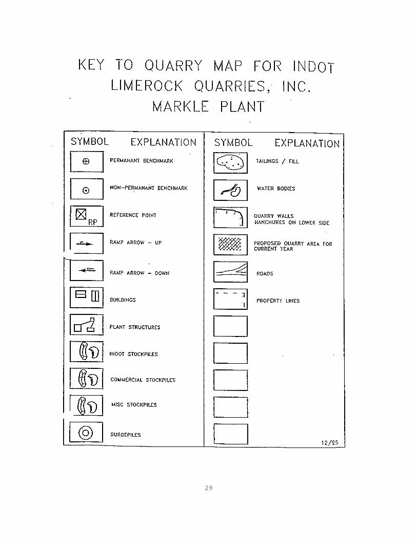
SECTION 11 - DOWNSTREAM CONTROL Identification of Stockpiles Stockpile Construction Material Retrieval SECTION 12 - LABORATORY Location Equipment Calibration SECTION 13 - DOCUMENTATION PLAN Referenced Documents Diary Test Data Control Charts Material Shipment Record SECTION 14 - ADDENDA APPENDIX A - ANNUAL SOURCE REPORT Report Location Map - General Stockpile Map Quarry Map Key to Quarry Map Geologic Cross - Sections APPENDIX B - AP PRODUCTION CONTROL PLAN APPENDIX C - FORMS Daily Diary Gradation Analysis Form Control Chart Random Number Form Shipping Record Form AUTHENTICATION
3
SECTION 1 PLANT LOCATION Limerock Quarries, Inc., Markle Plant (2799) is classified as a Plant for CAPP purposes. The location of the plant is indicated on the map in Appendix A. The address and other pertinent information is as follows: Limerock Quarries Inc. (INDOT #2799) 6593 County Rd. Bippus, IN 46713 Latitude - 40E 47' 58" Longitude - 85E 21' 26" County - Huntington Township - T 27 N Range - R 10 E Section - 11 Office Phone No. - 219-555-7214 Fax - 219-555-6032 Certified Technician Mobile - 219-555-8381 Lab - 219-555-4621 The Limerock Quarry is approximately 2.3 miles south of the town of Markle and west of SR 3. To locate the plant follow SR 3 south from Markle to CR 200S. At this intersection turn west, cross over Rock Creek and the entrance to the Quarry is the first right. The Limerock Quarry is owned by Stone City, Inc. which is located at the following address: Stone City, Inc. 5538 Subbase Ln. Mineral, IN 46220 317-257-1996 FAX: 317-257-1995

4
SECTION 2 ORGANIZATIONAL STRUCTURE MANAGEMENT REPRESENTATIVES The Quarry Superintendent for Limerock Quarries and Management Representative for this source is Clay Mudstone. He is responsible for all production for this site. CERTIFIED TECHNICIANS The CAPP Certified Aggregate Technician responsible for this location is Richard Quality. His duties include testing and reporting results from this site as well as assisting with the CAPP duties at several other sites within the Limerock organization. Mr. Quality communicates all CAPP concerns to Mr. Mudstone who then takes appropriate actions. Other Quality Control Personnel include Crystal Stone and Chip Samples. Ms. Stone's duties include sampling and reporting test results for three sites within Limerock Quarries, Inc. She may also assist at this site as the need arises. Mr. Samples is a CAPP Certified Aggregate Technician who will substitute for Mr. Quality when necessary.
5
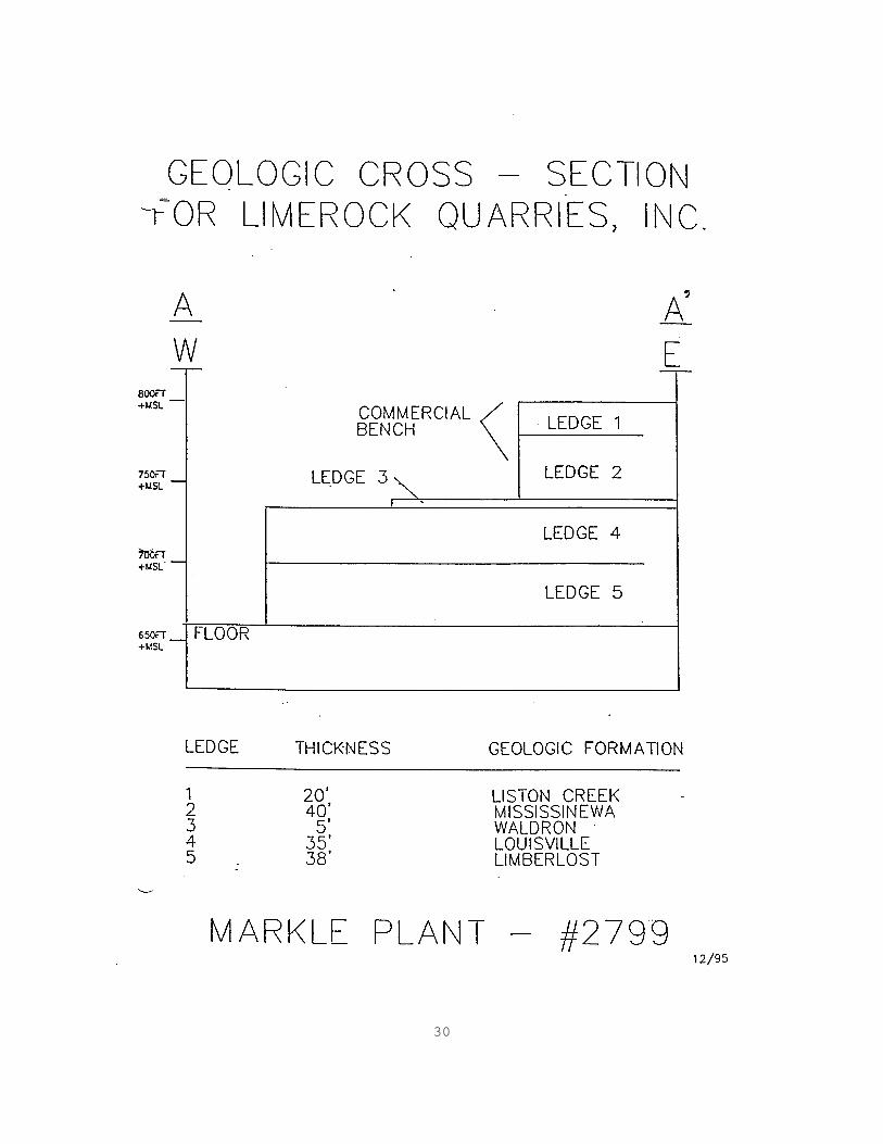
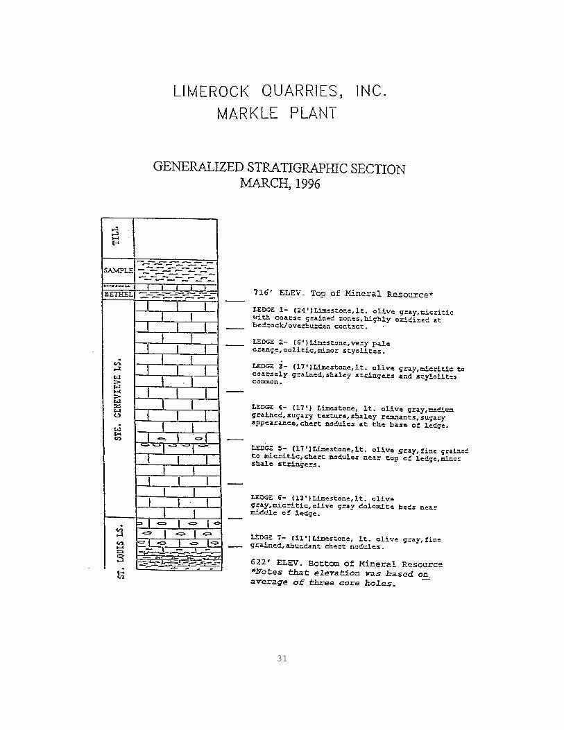
SECTION 3 MINERAL DEPOSITS All stone in the production areas are Silurian in age. The stone is derived from bedrock belonging to the Wabash and Pleasant Mills Formations and the Liston Creek, Mississinewa, Louisville and Limberlost Members. Ledges 1 and 2 are mined as one bench for commercial purposes only. Ledge 3 is not useable for any type of aggregate use and is stripped and wasted. Useable INDOT aggregates include only ledges 4 and 5, which are mined as one 73 foot thick bench. (A geologic cross-section of these ledges is provided in Appendix A). Test data and Class rating for these ledges appear in the Summary of Ledge Quality Tests letter dated March 31, 1993. This source is currently classified as Category 1A. Ledges 4 and 5 are allowed for use as AP aggregates and dolomite aggregates.

6
SECTION 4 AP AGGREGATE Ledges 4 and 5 are approved for Class AP aggregate production as indicated on the approval letter dated November 4, 1994. The AP Production Control Plan is included in Appendix B.

7
SECTION 5 MATERIAL CATEGORIES STANDARD SPECIFICATION Aggregates produced from ledges 4 and 5 are categorized as Standard Specification materials and include the following INDOT sizes: 2, 5, 8, AP 8, 9, 11, 12, 53, 73 ALTERNATE Aggregates produced from ledges 1 and 2 are categorized as Alternate materials and include the following INDOT sizes: 2, 53, 73, Rip Rap OTHER No. 23 natural sand is stockpiled at the on-site Tarcoat asphalt plant. This material is only used for the asphalt plant and is not sampled or tested by Limerock Quarries, Inc.

8
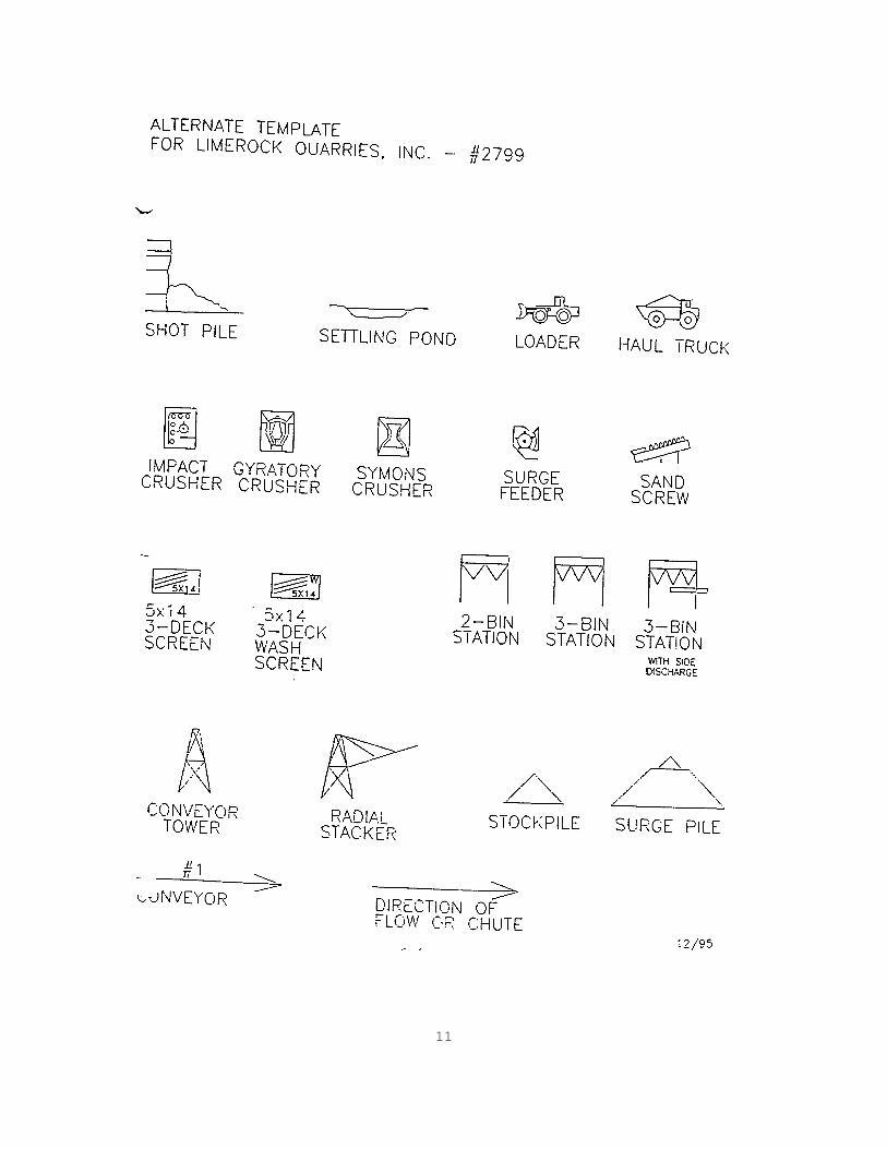
SECTION 6 PRODUCTION FLOW DIAGRAM Aggregates produced at this source are produced from 1 production area. Only those aggregates produced from ledges 4 and 5 are used for INDOT purposes. Therefore, the process description will be limited to those matters associated with production from these ledges. The flow diagram for the entire plant and detailed flow diagrams for stations #2 and #3 are shown on the following pages. Production of materials from ledges 4 and 5 is referred to as Class A production. This part of the plant is referred to as the A Circuit. Materials from the A Circuit that are in the muck pile are all removed with a loader and put into haul trucks. The trucks unload the aggregates into a Traylor 54" gyratory crusher where they are crushed and conveyed to the Primary Surge Pile. STATION #2 Material from the Primary Surge Pile is fed into Station #2 where the first screening is done with a Drister 5' x 14' 3-deck vibrating screen. The following materials are processed: 1. Oversized materials are closed-circuited to a 4'
shorthead Symons cone crusher where they are reduced and returned to Station #2.
2. Materials passing through the first deck and retained
on the second deck are #2 size and may either be diverted back to the 4' Symons crusher or routed to a bin where they are loaded into trucks for stockpiling.
3. Materials passing through the second deck and retained
on the third deck are always sent to Station #3. 4. Materials passing through all decks at this station are
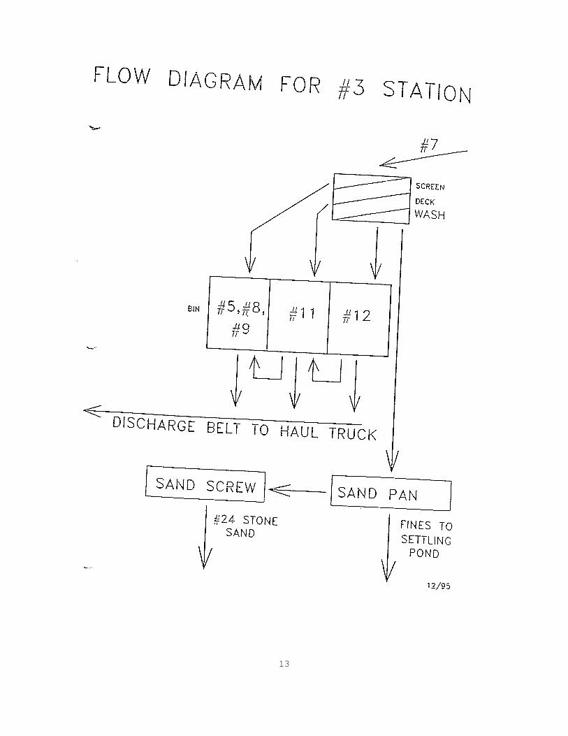
sent to the stacker and stockpiled as #53 or #73. STATION #3 Material from Station #2 is fed into this station which is the wash station. The screening unit is a 3-deck 5' x 14' Deister vibrating screen with water. The top deck has a combination of 1/2" and 3/8" screen panels, the middle deck has a combination of 1/4" and 5/16" screen panels and the bottom deck has .080" x 5/16" slotted panels or 1/8" square panels. These combinations can be changed to control our products. All materials arriving at this Station are pre-screened. The following materials are washed and stored.

9
1. Oversized materials are either #5, #8 or #9 and go into the coarse bin to await stockpiling.
2. Materials retained on the second screen go into the #11
bin. The #11 aggregate may either be stockpiled or combined with the coarse bin materials or both.
3. Materials retained on the third screen go into the #12
bin. The #12 aggregate may either be stockpiled or combined with the #11 aggregate or both.
4. Materials passing through all decks at this station are
sent to the stone sand screw to produce #24 manufactured fine aggregate. Fines from here go to the settling ponds.

10
11

12
13

14
SECTION 7 SAMPLING PLAN Limerock Quarries, Inc. has developed a coding scheme to distinguish the 5 different types of samples that are obtained. The type of samples, frequency of sampling, location of samples and sampling procedures of any Certified Materials are included as follows. TYPE OF SAMPLES AND FREQUENCY (S) Start of Production. After a seasonal shutdown or when producing a new material, start of production samples shall be obtained once every 1000 t for the first 5000 t, but shall not exceed 2 per calendar day. (N) Normal Production. After the start of production samples have been completed for each material, normal production samples shall be obtained. The frequency of these samples shall be once every 2000 t, but shall not exceed 2 per calendar day. (L) Load-Out. Load-out samples shall be taken from material that is shipped. The frequency of these samples shall be once every 8000 t; however, there shall be at least one sample taken each month for any Certified Material shipped that exceeds 1000 t. (M) Miscellaneous. Miscellaneous samples are taken at our own discretion for information purposes outside the start of production or normal production samples. (R) Resample. When there is a failing normal production or load-out test a resample shall be taken. MEANS OF TRACKING SAMPLES Start of production and normal production samples shall be taken on a random basis using the Random Number Form (Appendix C). The Quarry Superintendent shall be responsible for using this form and communicating with production staff as to when to obtain samples. If the random ton to be sampled is determined to be from the first or second load of the day then the third load shall be selected to sample. Shipping tonnages shall be kept by the office bookkeepers to determine when the load-out samples are to be obtained. The bookkeepers shall inform the Quarry Superintendent of when a sample is required.
15
SAMPLE LOCATIONS All start of production and normal production samples, except for #24 stone sand, shall be taken from the bins before incorporation into the stockpiles. No. 24 stone sand shall be sampled from a small pile of material that is stockpiled as it comes off of the sand screw. Load-out samples shall be taken from the Certified Material stockpiles. The points of sampling for all samples are indicated on the flow diagram on page 6-3. SAMPLING PROCEDURES Start of production and normal production samples, except for #24 stone sand, shall be dumped from a truck into a small stockpile. Sampling from these stockpiles shall be in accordance with ITM 207. No. 24 stone sand shall be sampled using the same procedure for the coarse aggregates after the small sample stockpile is rolled until it appears homogeneous. Load-out samples shall be sampled in accordance with ITM 207.
16
SECTION 8 TESTING PLAN GRADATION Gradation analysis shall be performed in accordance with AASHTO T 27 on all start of production, normal production and load-out samples. A gradation test shall be performed on resample and miscellaneous samples when necessary. DECANT Decant tests shall be performed in accordance with AASHTO T 11 on all load-out samples. DELETERIOUS The percent of deleterious materials shall be determined in accordance with AASHTO T 112 at least once per week for each size of material for the start of production and normal production samples. No test shall be performed if the week's production is less than 100 t. NON-CONFORMING MATERIAL Any time there is a failing normal production or load-out test the Quarry Superintendent shall be notified immediately and a resample test taken. Typically, retests shall be accompanied by a visual check for any problems at the plant. All actions shall be documented in the Daily Diary. In the event that a second consecutive normal production sample fails, the materials will be diverted until the problem is corrected. Failing INDOT sizes 2, 5, 8, 9, 11, 12 and 24 shall be taken to the scrap pile and wasted. Failing INDOT sizes 53 and 73 shall be incorporated into the commercial stockpiles. In the event that a second consecutive load-out sample fails, shipping from that stockpile shall cease. The stockpile problem area shall be checked to determine if the stockpile can be remixed and restored within the quality control limits as verified by the resample tests. If the problem area cannot be remixed, the material shall be removed and taken to the scrap pile.

17
SECTION 9 GRADATION CONTROL NO. 5 STONE 1/2 in. Critical Sieve x = 45.1%
σn-1 = 5.0 Upper Control Limit = 55.1% Lower Control Limit = 35.1% NO. 8 STONE 1.2 in. Critical Sieve
x = 49.0%
σn-1 = 5.0 Upper Control Limit = 59.0% Lower Control Limit = 39.0% NO. 9 STONE 3/8 in. Critical Sieve
x = 42.5%
σn-1 = 4.0 Upper Control Limit = 50.5% Lower Control Limit = 34.5% NO. 11 STONE No. 4 Critical Sieve
x = 22.2%
σn-1 = 4.7 Upper Control Limit = 31.6% Lower Control Limit = 12.8% NO. 12 STONE No. 4 Critical Sieve
x = 67.8%
σn-1 = 5.0 Upper Control Limit = 77.8% Lower Control Limit = 57.8%
18
SECTION 10 PROCESS CONTROL TECHNIQUES Los Angeles abrasion and absorption tests may be performed when deemed necessary and shall be posted on the Gradation Analysis Form (Appendix C). A visual check of all stockpiles is an ongoing daily procedure.
19
SECTION 11 DOWNSTREAM CONTROL IDENTIFICATION OF STOCKPILES All stockpiles shall be marked using signs in front of each stockpile that indicate the size of each material and the ledges the material is from. For Standard Specification stockpiles, the signs shall be blue with white lettering and for Alternate stockpiles, the signs shall be red with white lettering. STOCKPILE CONSTRUCTION Stockpiling of the aggregates is done by unloading truck loads side by side and then stacking the material only as high as the front-end loader can place the material. MATERIAL RETRIEVAL The entire front face of each stockpile shall be worked by a front-end loader from side to side when loading the truck. The sides of the face shall be occasionally mixed with the center to prevent segregation of the stockpile.
20
SECTION 12 LABORATORY LOCATION The laboratory is located near the west boundary of the property at the Bippus facility. The following verified equipment is maintained in the laboratory: EQUIPMENT Sieve Analysis Gilson TS-1 shaker 15 in. x 23 in. screens (2 in. (50 mm), 1½ in. (37.5
mm), 1 in. (25 mm), 3/4 in. (19.0 mm), 1/2 in. (12.5 mm), 3/8 in. (9.5 mm), No. 4 (4.75 mm) and pan)
Gilson Ro-Tap shaker 8 in. round sieves (3/8 in. (9.5 mm), No. 4 (4.75 mm),
No. 8 (2.36 mm), No. 16 (1.18 mm), No. 30 (600 µm), No. 50 (300 µm), No. 100 (150 µm), No. 200 (75 µm) and pan)
General Humboldt oven Ohaus IP12KS Digital Electronic Balance (12000 g capacity) Mettler H10 Electronic Balance (160 g capacity) CALIBRATION The balances, mechanical shakers, oven, and sieves shall be verified in accordance with the following: Minimum Equipment Frequency Procedure Balances 12 mo. ITM 910 Mechanical Shakers 12 mo. ITM 906 Sieves 12 mo. ITM 902
21
SECTION 13 DOCUMENTATION PLAN Several forms have been developed for the CAP program and all information regarding the CAPP shall be entered on these forms. Examples of these forms may be found in Appendix C. REFERENCE DOCUMENTS The following documents are on file at the lab: 1. INDOT Certified Aggregate Producer Program (ITM 211) 2. INDOT Standard Specifications and Current Supplemental
Specifications 3. INDOT Inspection and Sampling Procedures for Fine and
Coarse Aggregate 4. Indiana Quality Assurance Certified Aggregate
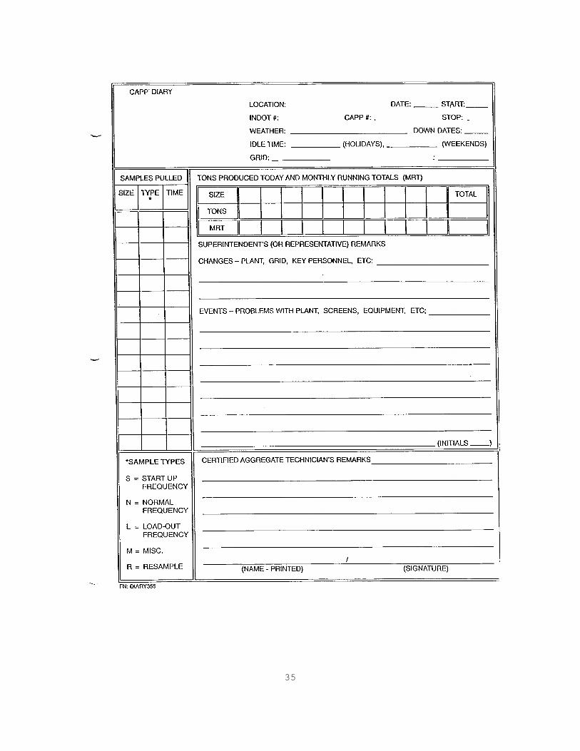
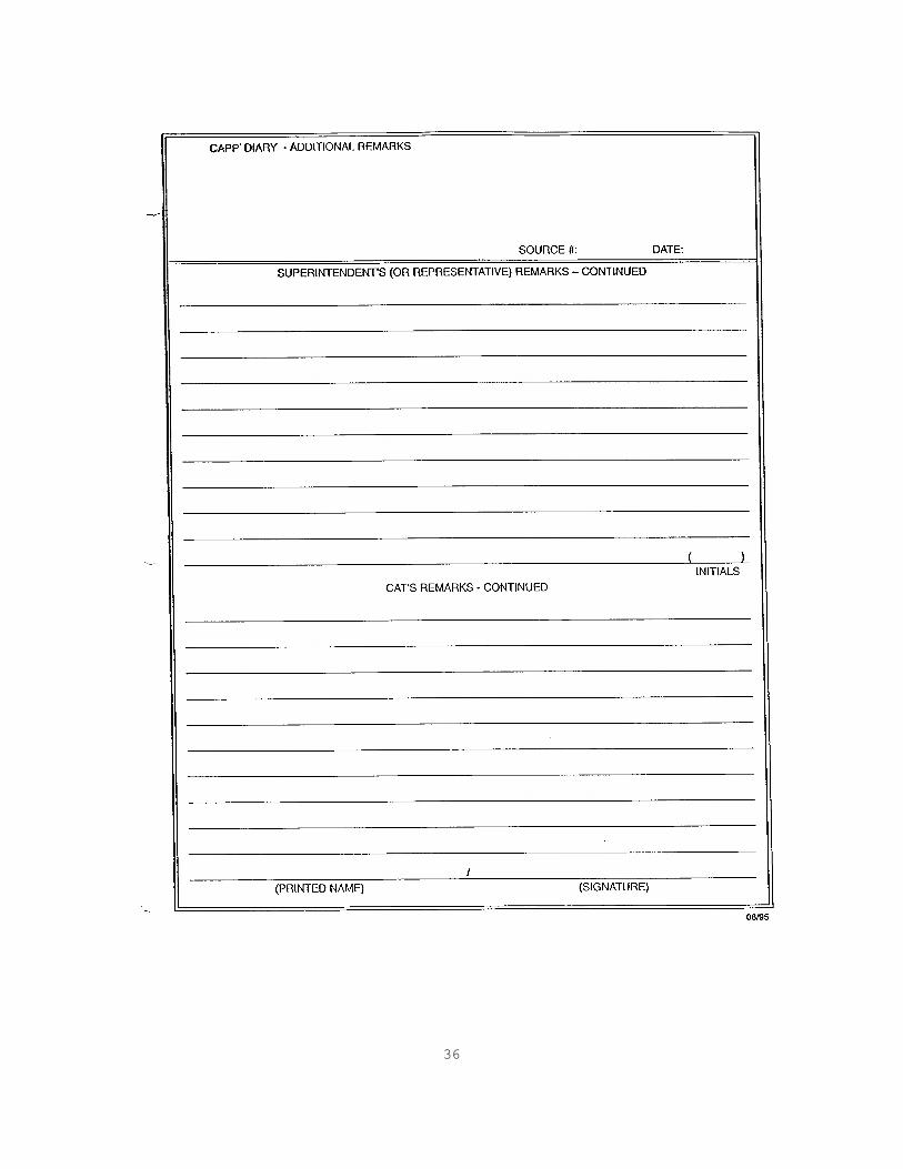
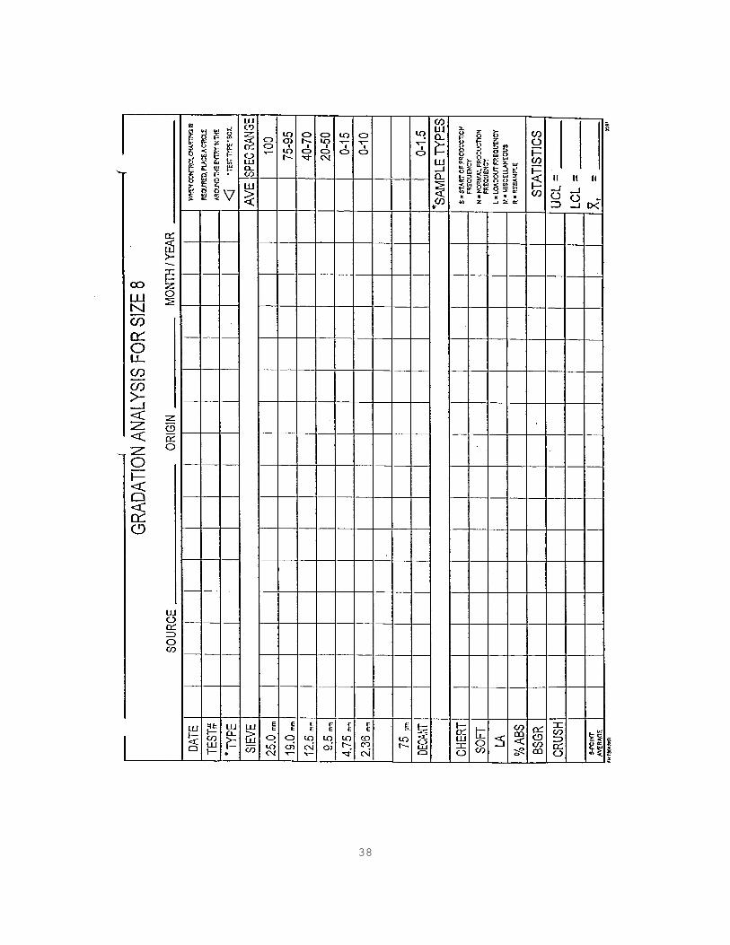
Technician Training Manual for Producer Technicians 5. Summary of Ledge Quality Results 6. Summary of Production Quality Results 7. AP Aggregate Letter 8. Quality Control Plan DIARY The diary is located in the Superintendent's office. One page is devoted to each day of the year that there is a material related operation and all the pages are maintained in a 3-ring binder. AGGREGATE INSPECTOR RECORD BOOK Each aggregate inspector working for this company is issued a number which is unique to that individual. Test data is recorded in the Aggregate Inspector Record Book and is traceable to any inspector through the identification number. This document is located in the laboratory. GRADATION ANALYSIS FORM This form is used for a quick visual comparison of up to 16 separate gradations of like materials. There is a different version of this form for each size of CAPP material including a generic version that may be used for any other material. This document is located in the laboratory.
22
CONTROL CHARTS Control charts for each size material are posted on the wall in the laboratory. We request that the following deviations be allowed to the control chart legend: 1. The target mean shall be placed at the appropriate
location on the critical sieve portion of the chart rather than the middle of the chart. It shall be represented by a heavy long dash followed by a short dash and the value shall be shown in the left-hand column. This change allows us to use one form for all of our sources.
2. The specification limits shall be solid lines instead
of short dashed lines. This makes for an overall more attractive control chart.
3. Because of the space limitations on an 11 in. x 17 in.
control chart, and that we plot all sieves for all sizes of stone, our charts do not always have a minimum of 2 in. between control limits. The charts, however, are very legible.
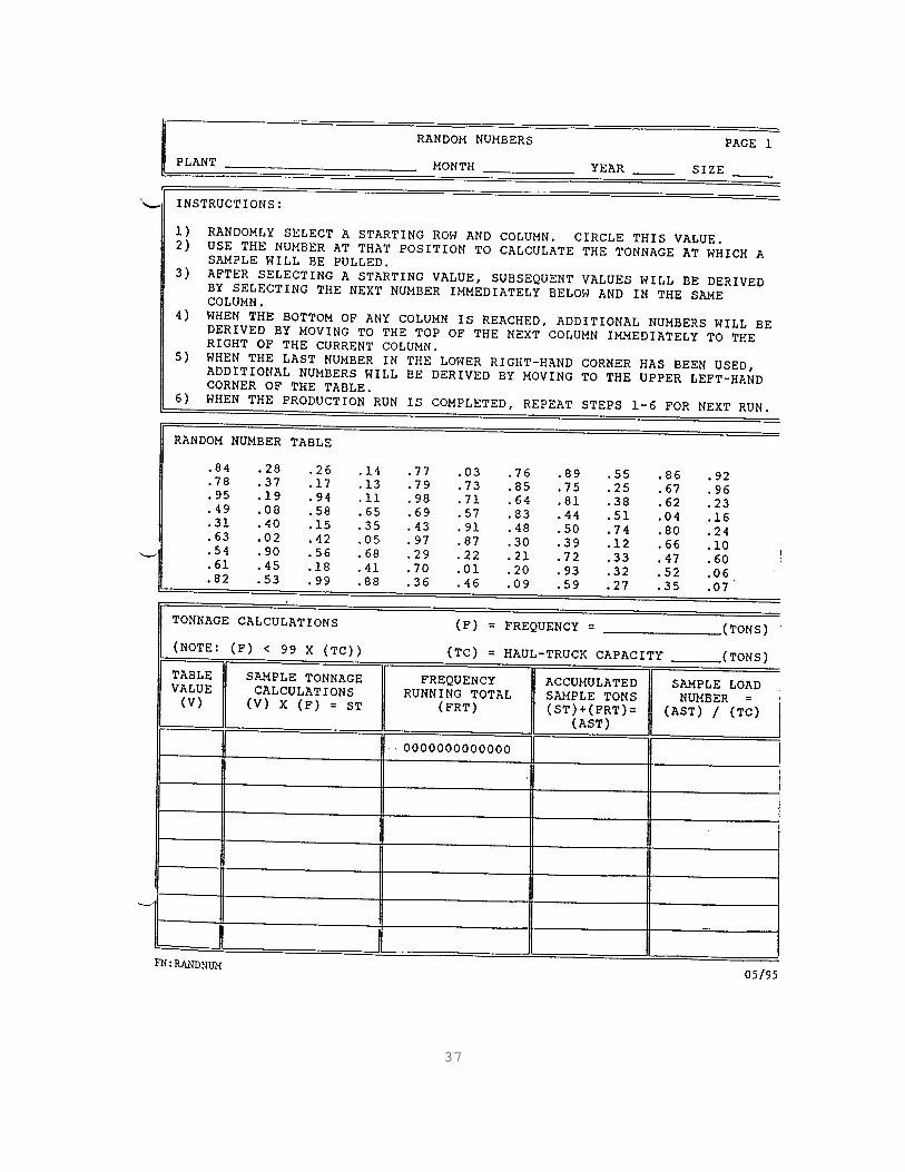
RANDOM NUMBER FORM This form was developed to assist the Quarry Superintendent in determining which loads shall be sampled for production control. INDOT MATERIAL SHIPPING RECORD FORM This form was developed to assist our bookkeepers in keeping track of how many tons of each material are shipped from the Certified Material stockpiles. This form is readily available to INDOT personnel at the office. SHOT CHART Information concerning the exact mining point of the materials being produced may be found in the shot chart. All production shots at this source are numbered. The assigned number has 2 parts: the first digit(s) represent the sequential order in which that shot was taken during a particular year and the last 2 digits represent the year of that shot (Example: 05-95 would be the fifth shot of 1995). The shot chart is kept with the Daily Diary and the shot number for a given production day is indicated in the diary. The shot chart may be cross-referenced to the original Quarry Map to determine the exact location of the point of mining of that material.
23
SECTION 14 ADDENDA Each page in the Quality Control Plan that is revised shall have the source number, date of revision, and a vertical line in the left margin indicating the paragraph that was revised. Revisions to the QCP shall be maintained on an Addenda Summary Sheet or QCP Annex in the Appendix until such time that the revisions are incorporated into the QCP. Addenda shall be submitted at the close-out meeting for an annual audit. Any outstanding revisions will also be submitted in January of each year along with the Annual Aggregate Source Report.

24
APPENDIX A ANNUAL SOURCE REPORT

25
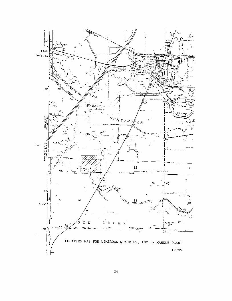
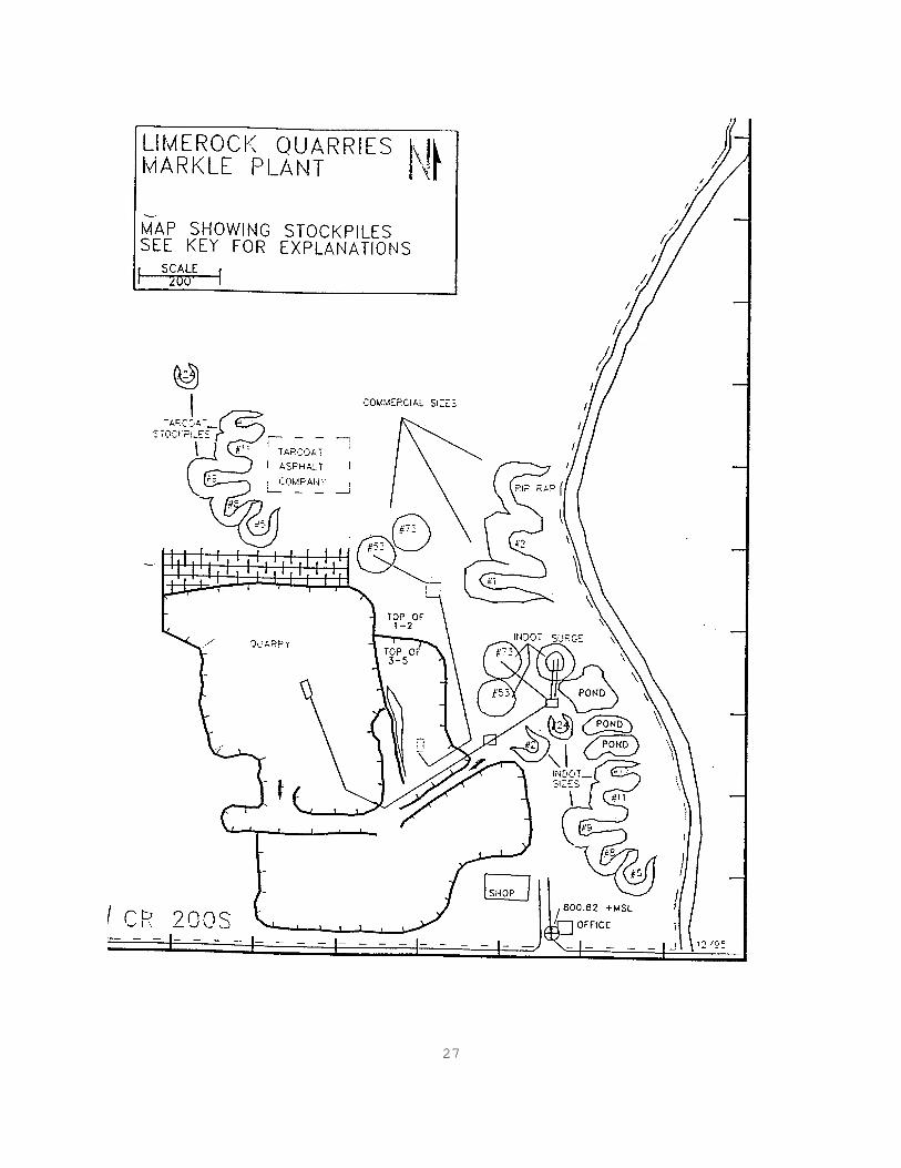
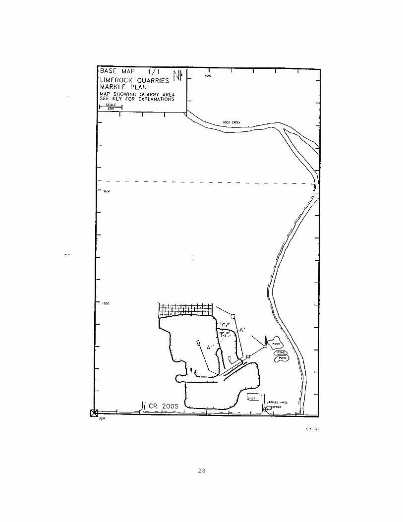
2000 ANNUAL SOURCE REPORT LIMEROCK QUARRIES, INC. INDOT SOURCE #2799 Limerock Quarries, Inc. is located in Huntington County, Indiana approximately 2.3 miles south of Markle, Indiana and one mile west of SR 3. The quarry property is within section 11, T 27 N and R 10 E. The Regional Manager is Ferris Ore, the Quarry Superintendent is Clay Mudstone and quality control is conducted by Richard Quality and Crystal Stone. INDOT may contact any of these persons as the need arises. This source currently operates two open-pit benches. The upper bench is mined for commercial purposes only and consists of ledges 1 and 2. Ledge 3 is not useable for any type of aggregate use and is stripped and wasted. The lower bench, containing ledges 4 and 5, is approximately 73' thick and is classified as Category IA, and Class AP materials. Elevations for all benches may be found on the following geologic cross-sections. A benchmark with an elevation of 800.82 ft. is located next to the office, which is southeast of the quarry. The proposed 1995 operating areas may be found on the following Source Map. Also included is the location map and quarry map indicating the stockpile areas.
26
27
28
29
30
31
32
APPENDIX B AP PRODUCTION CONTROL PLAN
33
AP PRODUCTION CONTROL PLAN LIMEROCK QUARRIES, INC. INDOT SOURCE #2799 Limerock Quarries, Inc. is approved for Class AP aggregate, and produces and controls stone meeting this classification in accordance with the following: 1. The production area for the AP stone is Ledges 4 and 5. 2. AP stone will be processed in accordance with the
procedures listed in Section 6. 3. The final production gradation for the AP stone will be
INDOT size #8 gradation. 4. The AP stockpile will be identified by a sign
indicating AP No. 8, Ledges 4 and 5, and the location and color of the size will be in accordance with Section 11. The No. 8 and AP 8 stockpiles will be separated by another stockpile of a different size.
5. AP stone delivered to concrete plants will be so
identified on the aggregate weigh tickets.

34
APPENDIX C FORMS
35
36
37
38

39

40
41
AUTHENTICATION APPROVAL SUBMISSION _________________________________ _________________________ Chief, Materials & Tests Division Management Representative ________________ __________________ Date of Approval Date of Submission


