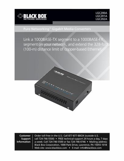
Link a 1000BASE-TX segment to a 1000BASE-FX segment on your network, and extend the 328-foot (100-m) distance limit of copper-based Ethernet. Pure Networking ™ Gigabit Media Converters LGC200A LGC201A LGC202A Order toll-free in the U.S.: Call 877-877-BBOX (outside U.S. call 724-746-5500) • FREE technical support 24 hours a day, 7 days a week: Call 724-746-5500 or fax 724-746-0746 • Mailing address: Black Box Corporation, 1000 Park Drive, Lawrence, PA 15055-1018 Web site: www.blackbox.com • E-mail: [email protected]Customer Support Information
Transcript
BLACK BOX®Link a 1000BASE-TX segment to a 1000BASE-FX
segment on your network, and extend the 328-foot (100-m) distance limit of copper-based Ethernet.
Pure Networking™ Gigabit Media Converters
LGC200A LGC201A LGC202A
Order toll-free in the U.S.: Call 877-877-BBOX (outside U.S. call 724-746-5500) • FREE technical support 24 hours a day, 7 days a week: Call 724-746-5500 or fax 724-746-0746 • Mailing address: Black Box Corporation, 1000 Park Drive, Lawrence, PA 15055-1018Web site: www.blackbox.com • E-mail: [email protected]
Customer Support
Information
724-746-5500 | blackbox.com Page 2
Trademarks Used in this Manual
Trademarks Used in this Manual
Black Box and the Double Diamond logo are registered trademarks, and Pure Networking is a trademark, of BB Technologies, Inc.
Any other trademarks mentioned in this manual are acknowledged to be the property of the trademark owners.
724-746-5500 | blackbox.com Page 3
FCC and IC RFI Statements
FEDERAL COMMUNICATIONS COMMISSION AND INDUSTRY CANADA RADIO FREQUENCY INTERFERENCE STATEMENTS
Class B Digital Device. This equipment has been tested and found to comply with the limits for a Class B computing device pursuant to Part 15 of the FCC Rules. These limits are designed to provide reasonable protection against harmful interfer-ence in a residential installation. However, there is no guarantee that interference will not occur in a particular installation. This equipment generates, uses, and can radiate radio frequency energy, and, if not installed and used in accordance with the instructions, may cause harmful interference to radio communications. If this equipment does cause harmful interference to radio or telephone reception, which can be determined by turning the equipment off and on, the user is encouraged to try to correct the interference by one of the following measures:
• Reorient or relocate the receiving antenna.
• Increase the separation between the equipment and receiver.
• Connect the equipment into an outlet on a circuit different from that to which the receiver is connected.
• Consult an experienced radio/TV technician for help.
Caution:
Changes or modifications not expressly approved by the party responsible for com-pliance could void the user’s authority to operate the equipment.
To meet FCC requirements, shielded cables and power cords are required to con-nect this device to a personal computer or other Class B certified device.
This digital apparatus does not exceed the Class B limits for radio noise emission from digital apparatus set out in the Radio Interference Regulation of Industry Canada.
Le présent appareil numérique n’émet pas de bruits radioélectriques dépassant les limites applicables aux appareils numériques de classe B prescrites dans le Règlement sur le brouillage radioélectrique publié par Industrie Canada.
1. Todas las instrucciones de seguridad y operación deberán ser leídas antes de que el aparato eléctrico sea operado.
2. Las instrucciones de seguridad y operación deberán ser guardadas para referencia futura.
3. Todas las advertencias en el aparato eléctrico y en sus instrucciones de operación deben ser respetadas.
4. Todas las instrucciones de operación y uso deben ser seguidas.
5. El aparato eléctrico no deberá ser usado cerca del agua—por ejemplo, cerca de la tina de baño, lavabo, sótano mojado o cerca de una alberca, etc.
6. El aparato eléctrico debe ser usado únicamente con carritos o pedestales que sean recomendados por el fabricante.
7. El aparato eléctrico debe ser montado a la pared o al techo sólo como sea recomendado por el fabricante.
8. Servicio—El usuario no debe intentar dar servicio al equipo eléctrico más allá a lo descrito en las instrucciones de operación. Todo otro servicio deberá ser referido a personal de servicio calificado.
9. El aparato eléctrico debe ser situado de tal manera que su posición no interfiera su uso. La colocación del aparato eléctrico sobre una cama, sofá, alfombra o superficie similar puede bloquea la ventilación, no se debe colocar en libreros o gabinetes que impidan el flujo de aire por los orificios de ventilación.
10. El equipo eléctrico deber ser situado fuera del alcance de fuentes de calor como radiadores, registros de calor, estufas u otros aparatos (incluyendo amplificadores) que producen calor.
11. El aparato eléctrico deberá ser connectado a una fuente de poder sólo del tipo descrito en el instructivo de operación, o como se indique en el aparato.
724-746-5500 | blackbox.com Page 5
NOM Statement
12. Precaución debe ser tomada de tal manera que la tierra fisica y la polarización del equipo no sea eliminada.
13. Los cables de la fuente de poder deben ser guiados de tal manera que no sean pisados ni pellizcados por objetos colocados sobre o contra ellos, poniendo particular atención a los contactos y receptáculos donde salen del aparato.
14. El equipo eléctrico debe ser limpiado únicamente de acuerdo a las recomendaciones del fabricante.
15. En caso de existir, una antena externa deberá ser localizada lejos de las lineas de energia.
16. El cable de corriente deberá ser desconectado del cuando el equipo no sea usado por un largo periodo de tiempo.
17. Cuidado debe ser tomado de tal manera que objectos liquidos no sean derramados sobre la cubierta u orificios de ventilación.
18. Servicio por personal calificado deberá ser provisto cuando:
A: El cable de poder o el contacto ha sido dañado; u
B: Objectos han caído o líquido ha sido derramado dentro del aparato; o
C: El aparato ha sido expuesto a la lluvia; o
D: El aparato parece no operar normalmente o muestra un cambio en su desempeño; o
E: El aparato ha sido tirado o su cubierta ha sido dañada.
5. Operation .................................................................................................23 5.1 LEDs on the Media Converter ......................................................23 5.2 Force/Auto Switch ........................................................................ 25
6. Troubleshooting........................................................................................ 26 6.1 Contacting Black Box .................................................................... 26 6.2 Shipping and Packaging ............................................................... 26
724-746-5500 | blackbox.com Page 7
Chapter 1: Specifications
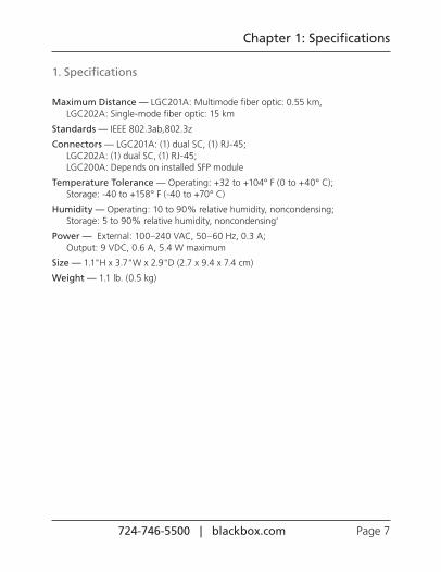
1. Specifications
Maximum Distance — LGC201A: Multimode fiber optic: 0.55 km, LGC202A: Single-mode fiber optic: 15 km
Temperature Tolerance — Operating: +32 to +104° F (0 to +40° C); Storage: -40 to +158° F (-40 to +70° C)
Humidity — Operating: 10 to 90% relative humidity, noncondensing; Storage: 5 to 90% relative humidity, noncondensing'
Power — External: 100–240 VAC, 50–60 Hz, 0.3 A; Output: 9 VDC, 0.6 A, 5.4 W maximum
Size — 1.1"H x 3.7"W x 2.9"D (2.7 x 9.4 x 7.4 cm)
Weight — 1.1 lb. (0.5 kg)
724-746-5500 | blackbox.com Page 8
Chapter 2: Overview
2. Overview
2.1 IntroductionThe Pure Networking LGC200A, LGC201A and LGC202A are Gigabit Media Converters. The SFP port of the LGC200A supports hot-swappable, Gigabit SFP modules. The LGC201A has a dual SC multimode fiber connector, and the LGC202A has a dual SC single-mode fiber connector.
Use the media converters to join a 1000BASE-TX segment to a 1000BASE-SX or 1000BASE-LX segment on your network, or use them in pairs to extend the 328-feet (100-m) distance limitation of copper-based Ethernet.
Three converter models are available:
• LGC200A: This SFP module media converter transmits/receives data based on the SFP module that is installed.
• LGC201A: This fiber SC media converter transmits/receives data by 850-nm short-wave laser over multimode fiber.
• LGC202A: This fiber SC media converter transmits/receives data by 1310-nm short-wave laser over single-mode fiber.
2.2 Features• Complies with 802.3ab and 802.3z standards.
• Provides (1) SC/LC connector or (1) SFP module slot and (1) RJ-45 connector.
• Both TX and FX ports work at 1000 Mbps in full-duplex mode.
• Supports Auto MDI/MDI-X for the TX port.
• Extends fiber distance up to 0.55 kilometers for multimode fiber and 15 kilometers for single-mode fiber.
• Easy-to-view LED indicators provide status to easily monitor network activity.
• Uses a 9-VDC, 600 mA external power supply (included).
724-746-5500 | blackbox.com Page 9
Chapter 2: Overview
2.3 What’s IncludedYour package should contain the following items. If anything is missing or damaged, contact Black Box Technical Support at 724-746-5500 or [email protected].
• (1) Pure Networking Gigabit Media Converter
• (1) 9-VDC, 600 mA power adapter
• This user’s manual
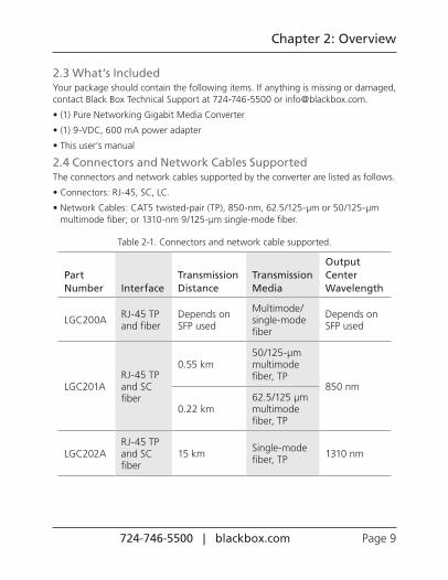
2.4 Connectors and Network Cables SupportedThe connectors and network cables supported by the converter are listed as follows.
• Connectors: RJ-45, SC, LC.
• Network Cables: CAT5 twisted-pair (TP), 850-nm, 62.5/125-µm or 50/125-µm multimode fiber; or 1310-nm 9/125-µm single-mode fiber.
Table 2-1. Connectors and network cable supported.
Part Number Interface
Transmission Distance
Transmission Media
Output Center Wavelength
LGC200A RJ-45 TP and fiber
Depends on SFP used
Multimode/single-mode fiber
Depends on SFP used
LGC201ARJ-45 TP and SC fiber
0.55 km50/125-µm multimode fiber, TP
850 nm
0.22 km62.5/125 µm multimode fiber, TP
LGC202ARJ-45 TP and SC fiber
15 km Single-mode fiber, TP 1310 nm
724-746-5500 | blackbox.com Page 10
Chapter 2: Overview
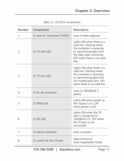
2.5 Hardware DescriptionFigures 2-1 through 2-6 show the front and back panels of the media converters. Tables 2-2 through 2-4 describe their components.
2.5.1 LGC201A
5 6
1 2 3 4
Figure 2-1. Front panel of the LGC201A.
7 8
Figure 2-2. Back panel of the LGC201A.
724-746-5500 | blackbox.com Page 11
Chapter 2: Overview
Table 2-2. LGC201A components.
Number Component Description
1 (1) dual SC connector (TX/RX) Links to fiber segment
2 (1) FX Link LED
Lights ON when there is a valid link. Flashing when the converter is receiving or transmitting data from the fiber optic connector. OFF when there is no valid link.
3 (1) TP Link LED
Lights ON when there is a valid link. Flashing when the converter is receiving or transmitting data from the twisted-pair port. OFF when there is no valid link.
4 (1) RJ-45 connector Links to 1000BASE-T device
5 (1) PWR LEDLights ON when power to the chassis is on; OFF when power is off.
6 (1) RX LED
Lights ON when the TP port is connected to 1000BASE-TX. OFF when the TP port is not connected.
7 (1) barrel connector Links to power
8 (1) switch for the FX port Selects Force or Auto-negotiation mode
724-746-5500 | blackbox.com Page 12
Chapter 2: Overview
*See Table 5-1 for LED functions.
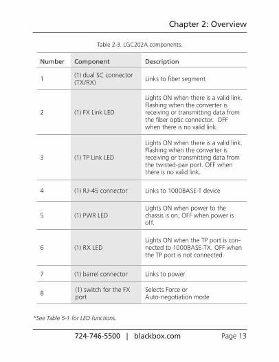
2.5.2 LGC202A
5 6
1 2 3 4
Figure 2-3. Front panel of the LGC202A.
7 8
Figure 2-4. Back panel of the LGC202A.
724-746-5500 | blackbox.com Page 13
Chapter 2: Overview
Table 2-3. LGC202A components.
Number Component Description
1 (1) dual SC connector (TX/RX) Links to fiber segment
2 (1) FX Link LED
Lights ON when there is a valid link. Flashing when the converter is receiving or transmitting data from the fiber optic connector. OFF when there is no valid link.
3 (1) TP Link LED
Lights ON when there is a valid link. Flashing when the converter is receiving or transmitting data from the twisted-pair port. OFF when there is no valid link.
4 (1) RJ-45 connector Links to 1000BASE-T device
5 (1) PWR LEDLights ON when power to the chassis is on; OFF when power is off.
6 (1) RX LEDLights ON when the TP port is con-nected to 1000BASE-TX. OFF when the TP port is not connected.
7 (1) barrel connector Links to power
8 (1) switch for the FX port
Selects Force or Auto-negotiation mode
*See Table 5-1 for LED functions.
724-746-5500 | blackbox.com Page 14
Chapter 2: Overview
2.5.3 LGC200A
5 6
1 2 3 4
Figure 2-5. Front panel of the LGC200A.
7 8
Figure 2-6. Back panel of the LGC200A.
724-746-5500 | blackbox.com Page 15
Chapter 2: Overview
Table 2-4. LGC200A components.
Number Component Description
1 (1) SFP slot for SFP module Links to fiber segment
2 (1) FX Link LED
Lights ON when there is a valid link. Flashing when the converter is receiving or transmitting data from the fiber optic connector. OFF when there is no valid link.
3 (1) TP Link LED
Lights ON when there is a valid link. Flashing when the converter is receiving or transmitting data from the twisted-pair port. OFF when there is no valid link.
4 (1) RJ-45 connector Links to 1000BASE-T device
5 (1) PWR LEDLights ON when power to the chassis is on; OFF when power is off.
6 (1) RX LED
Lights ON when the TP port is connected to 1000BASE-TX. OFF when the TP port is not connected.
7 (1) barrel connector Links to power
8 (1) switch for the FX port Selects Force or Auto-negotiation mode
724-746-5500 | blackbox.com Page 16
Chapter 3: Configuration
3. Configuration
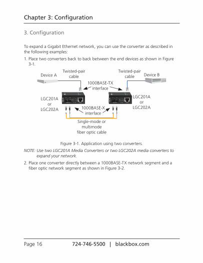
To expand a Gigabit Ethernet network, you can use the converter as described in the following examples:
1. Place two converters back to back between the end devices as shown in Figure 3-1.
Device A Device B
LGC201A or
LGC202A
LGC201A or
LGC202A
Twisted-pair cable
Twisted-pair cable
Single-mode or multimode
fiber optic cable
1000BASE-TX interface
1000BASE-X interface
Figure 3-1. Application using two converters.
NOTE: Use two LGC201A Media Converters or two LGC202A media converters to expand your network.
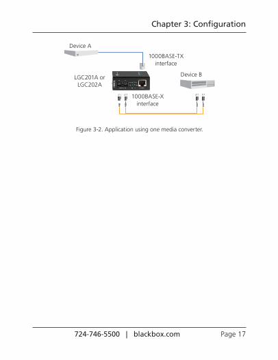
2. Place one converter directly between a 1000BASE-TX network segment and a fiber optic network segment as shown in Figure 3-2.
724-746-5500 | blackbox.com Page 17
Chapter 3: Configuration
Device A
Device B
1000BASE-TX interface
1000BASE-X interface
LGC201A or LGC202A
Figure 3-2. Application using one media converter.
724-746-5500 | blackbox.com Page 18
Chapter 4: Installation
4. Installation
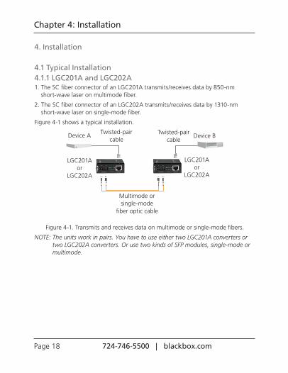
4.1 Typical Installation4.1.1 LGC201A and LGC202A1. The SC fiber connector of an LGC201A transmits/receives data by 850-nm
short-wave laser on multimode fiber.
2. The SC fiber connector of an LGC202A transmits/receives data by 1310-nm short-wave laser on single-mode fiber.
Figure 4-1 shows a typical installation.
Device A Device B
LGC201A or
LGC202A
LGC201A or
LGC202A
Twisted-pair cable
Twisted-pair cable
Multimode or single-mode
fiber optic cable
Figure 4-1. Transmits and receives data on multimode or single-mode fibers.
NOTE: The units work in pairs. You have to use either two LGC201A converters or two LGC202A converters. Or use two kinds of SFP modules, single-mode or multimode.
724-746-5500 | blackbox.com Page 19
Chapter 4: Installation
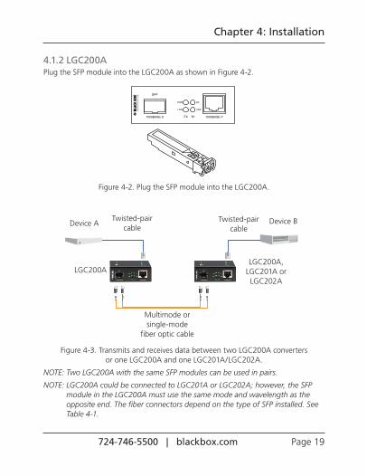
4.1.2 LGC200APlug the SFP module into the LGC200A as shown in Figure 4-2.
Figure 4-2. Plug the SFP module into the LGC200A.
LGC200A LGC200A,
LGC201A or LGC202A
Device A Device BTwisted-pair cable
Twisted-pair cable
Multimode or single-mode
fiber optic cable
Figure 4-3. Transmits and receives data between two LGC200A converters or one LGC200A and one LGC201A/LGC202A.
NOTE: Two LGC200A with the same SFP modules can be used in pairs.
NOTE: LGC200A could be connected to LGC201A or LGC202A; however, the SFP module in the LGC200A must use the same mode and wavelength as the opposite end. The fiber connectors depend on the type of SFP installed. See Table 4-1.
724-746-5500 | blackbox.com Page 20
Chapter 4: Installation
Table 4-1. LGC200A LC to LGC201A or LGC202A SC connection.
Part Number LGC200A LGC201A LGC202A
Transmision Media
SFP module850-nm multimode
1310-nm single-mode
4.2 Installation ProcedureUse a fiber cable to connect two converters and extend a copper link or to connect a 1000BASE-FX segment to a 1000BASE-X segment on your network.
1. Connect a converter to a 1000BASE-TX device (hub or switch).
• Make sure that the CAT5 twisted pair cable between the 1000BASE-TX device and the converter is less than 328 feet (100) meters long.
• Connect one end of the CAT5 twisted pair cable to the RJ-45 jack on the convert-er and the other end of the cable to the RJ-45 jack on the 1000BASE-TX device.
2. Connect two converters or a converter and a 1000BASE-FX device.
• Use an SC fiber cable to connect the two converters’ SC connector or the SC connector of a converter and a 1000BASE-FX device.
3. Turn on the power.
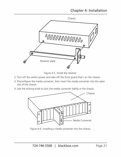
4.3 Install the Media Converter into the LHC200A-RACK1. Take out the two screws located on the top of the chassis and use them to install
the retainer as shown in Figure 4-5.
724-746-5500 | blackbox.com Page 21
Chapter 4: Installation
Retainer plate
Chassis
Figure 4-5. Install the retainer.
2. Turn off the switch power and take off the front guard that’s on the chassis.
3. Preconfigure the media converter, then insert the media converter into the open slot of the chassis.
4. Use the locking knob to lock the media converter tightly in the chassis.
Media Converter
Figure 4-6. Installing a media converter into the chassis.
Chassis
724-746-5500 | blackbox.com Page 22
Chapter 4: Installation
5. Turn on the power switch and you will see the media converter’s Power LED light. Then you can operate it in the same way as a standalone Pure Networking Media Converter.
724-746-5500 | blackbox.com Page 23
Chapter 5: Operation
5. Operation
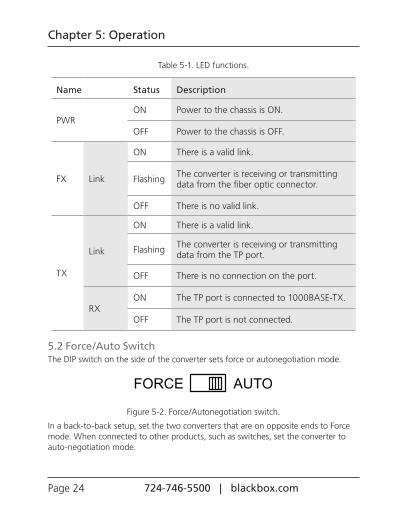
5.1 LEDs on the Media ConvertersThe converters have real-time LED indicators that can provide real-time status reports. Just look at the LEDs to deterimine the link status. Figure 5-1 shows the LEDs, and Table 5-1 describes their functions.
Figure 5-1. LEDs.
724-746-5500 | blackbox.com Page 24
Chapter 5: Operation
Table 5-1. LED functions.
Name Status Description
PWRON Power to the chassis is ON.
OFF Power to the chassis is OFF.
FX Link
ON There is a valid link.
Flashing The converter is receiving or transmitting data from the fiber optic connector.
OFF There is no valid link.
TX
Link
ON There is a valid link.
Flashing The converter is receiving or transmitting data from the TP port.
OFF There is no connection on the port.
RXON The TP port is connected to 1000BASE-TX.
OFF The TP port is not connected.
5.2 Force/Auto SwitchThe DIP switch on the side of the converter sets force or autonegotiation mode.
Figure 5-2. Force/Autonegotiation switch.
In a back-to-back setup, set the two converters that are on opposite ends to Force mode. When connected to other products, such as switches, set the converter to auto-negotiation mode.
724-746-5500 | blackbox.com Page 25
Chapter 6: Troubleshooting
6. Troubleshooting
6.1 Contacting Black BoxIf you determine that your Pure Networking Gigabit Media Converter is malfunctioning, do not attempt to alter or repair the unit. It contains no user-serviceable parts. Contact Black Box Technical Support at 724-746-5500 or [email protected].
Before you do, make a record of the history of the problem. We will be able to provide more efficient and accurate assistance if you have a complete description, including:
• the nature and duration of the problem.
• when the problem occurs.
• the components involved in the problem.
• any particular application that, when used, appears to create the problem or make it worse.
6.2 Shipping and PackagingIf you need to transport or ship your Pure Networking Gigabit Media Converter:
• Package it carefully. We recommend that you use the original container.
• If you are returning the unit, make sure you include everything you received with it. Before you ship for return or repair, contact Black Box to get a Return Authorization (RA) number.
724-746-5500 | blackbox.com Page 26
NOTES
724-746-5500 | blackbox.com Page 27
NOTES
Chapter
Page 900 724-746-5500 | blackbox.com
BLACK BOX®
Great tech support is just 30 seconds away at 724-746-5500 or blackbox.com.
Black Box Tech Support: FREE! Live. 24/7.
Tech support the way it should be.
LGC200A/LGC201A/LGC202A, version 1
About Black BoxBlack Box provides an extensive range of networking and infrastructure products. You’ll find everything from cabinets and racks and power and surge protection products to media converters and Ethernet switches all supported by free, live 24/7 Tech support available in 30 seconds or less.