18
Operator’s Manual Litter Spreader Models SP400, SP450, SP500 & SP550 ® ® THIS MANUAL MUST BE READ AND UNDERSTOOD BEFORE ANYONE OPERATES THIS MACHINE! Manual# 990031 Revised 08/2016

Operator’s Manual
Litter SpreaderModels SP400, SP450,
SP500 & SP550
®®
THIS MANUAL MUST BE READ AND UNDERSTOOD BEFORE ANYONE OPERATES THIS MACHINE!
Manual# 990031Revised 08/2016
YOU MUST FILL OUT YOUR WARRANTY REGISTRATION TO ACTIVATE YOUR WARRANTY AND TO QUALIFY FOR PARTS AND SERVICE!!
To the Owner;Thank-You for choosing a quality spreader from Pequea Machine, Inc. We strive to give you the best equipment and the best level of service of any company. With a little care and maintenance this machine will do your work for you for many years. In this manual, we make an effort to get you better acquainted with the spreader so you can achieve maximum performance. We design and build all of our equipment with the end user in mind so we welcome any suggestions or ideas for improvement.
Please take a few minutes to fill out the area below. This information will be valuable to you when ordering parts or requesting service from your dealer.
Dealer Name:_____________________________
Dealer Phone Number:______________________
Service Manager/Technician:_________________
Model# and Description:_____________________
Serial Number:____________________________
Date of Purchase:__________________________
1
TABLE OF CONTENTSIntroduction ……………………………………………………………… 2
Serial Number ……………….……………………………… 2Specifications ………………………………………………… 2
Safety ………………………………………………………………………… 3General Safety Guidelines ………………………………… 3Safety Decals and Reflectors ……………………………… 4
Hitching ……………………………………………………………………… 5Tractor Requirements ………………..……………………… 5Attaching to the Tractor …………………..………………… 5
Camera Setup/Wiring…………………………………………………… 6Transport …………………………………………………………………… 8
Field Transport ……………………………………………… 8Road Transport ……………………………………………… 8
Operation ……………………………………………………………..…… 9Maintenance ……………………………………………………………… 10
General Maintenance .…………………………………… 10Wheel & Tire Maintenance ……………………………...… 10Wheel Bearing Maintenance …………………………….… 10Grease Fitting Lubrication ………………………………..… 10Apron Chain Maintenance …………………………..……… 11Hydraulic System Maintenance ……………………………11
Warranty ………………………………………………………………… 12Notes ……………………………………………………………………… 13

2
INTRODUCTIONThank-You for choosing the Pequea Litter Spreader. Your spreader is the result of years of re-search and development work. This Operator’s Manual will familiarize the operator with the safety and operation of the machine. Included are complete instructions for safe and efficient operation, lubrication, and maintenance procedures. Understanding and following these procedures will result in years of maximum performance from your Pequea Spreader.
Read entire manual before operating. Failure to follow the instructions outlined in this manual may result in personal injury and/or damaged equipment, and could void the war-ranty. Serial Number
The serial number consists of five numerical digits and can be found on a small yellow sticker on the left front corner of the spreader box. Please use this number when requesting service, seeking informa-tion, or ordering parts. For the operator’s conve-nience, space to record the serial number, model number, purchase date, and dealer has been pro-vided inside the front cover of this manual.
Specifications
All pictures and instructions in this manual assume that the right and left side of the machine are that of someone standing behind the machine facing forward.
Standard Features SP-400 SP-450 SP-500 SP-550Hopper Length 16’ 18’ 20’ 22’Hopper width (at top) 96” 96” 96” 96”Overall Height 89” 89” 90” 91”Overall Length 26’ 28’ 30’ 32’Overall Width 97” 97” 98” 99”Tires 16.5L-16.1SL 10 ply 16.5L-16.1SL 10 ply 21.5L-16.1SL 10 ply 21.5L-16.1SL 14 plyMaterial Cap. Struck level - Heaped 290-450 Cu. Ft. 360-490 Cu. Ft. 400-530 Cu. Ft. 450-580 Cu. Ft.Payload 20,000 lbs 20,500 lbs 24,000 lbs 27,000 lbsEmpty Weight 6,000 lbs 6,200 lbs 6,600 lbs 7,850 lbsWeight on Tongue (Empty Hopper) 1,000 lbs 1,020 lbs 1,040 lbs 1,060 lbsHeavy Duty Tandem Axle Standard Standard Standard StandardFull length Fenders Standard Standard Standard StandardSight Window Standard Standard Standard Standard
3/4 x 6 Tongue & Groove Poly Floor Standard Standard Standard StandardHeavy Duty 88K Chain Standard Standard Standard StandardRemovable Spinner Attachment Standard Standard Standard StandardSpinner Disc Thickness 1/4” plate 1/4” plate 1/4” plate 1/4” plateSpinner Diameter 25” 25” 25” 25”Spinner Paddles (6) bolt on reinforced (6) bolt on reinforced (6) bolt on reinforced (6) bolt on reinforced
Figure 1
3
SAFETY
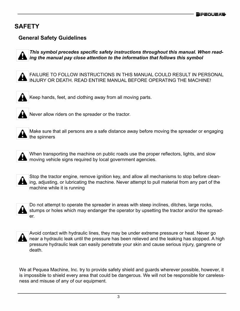
This symbol precedes specific safety instructions throughout this manual. When read-ing the manual pay close attention to the information that follows this symbol
FAILURE TO FOLLOW INSTRUCTIONS IN THIS MANUAL COULD RESULT IN PERSONAL INJURY OR DEATH. READ ENTIRE MANUAL BEFORE OPERATING THE MACHINE!
Keep hands, feet, and clothing away from all moving parts.
Never allow riders on the spreader or the tractor.
Make sure that all persons are a safe distance away before moving the spreader or engaging the spinners
When transporting the machine on public roads use the proper reflectors, lights, and slow moving vehicle signs required by local government agencies.
Stop the tractor engine, remove ignition key, and allow all mechanisms to stop before clean-ing, adjusting, or lubricating the machine. Never attempt to pull material from any part of the machine while it is running
Do not attempt to operate the spreader in areas with steep inclines, ditches, large rocks, stumps or holes which may endanger the operator by upsetting the tractor and/or the spread-er.
Avoid contact with hydraulic lines, they may be under extreme pressure or heat. Never go near a hydraulic leak until the pressure has been relieved and the leaking has stopped. A high pressure hydraulic leak can easily penetrate your skin and cause serious injury, gangrene or death.
We at Pequea Machine, Inc. try to provide safety shield and guards wherever possible, however, it is impossible to shield every area that could be dangerous. We will not be responsible for careless-ness and misuse of any of our equipment.
General Safety Guidelines
4
SAFETY
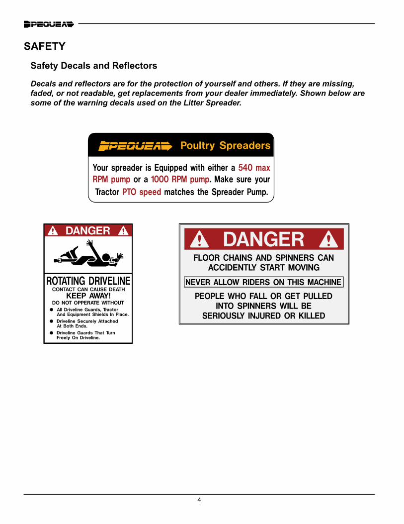
Safety Decals and Reflectors
Decals and reflectors are for the protection of yourself and others. If they are missing, faded, or not readable, get replacements from your dealer immediately. Shown below are some of the warning decals used on the Litter Spreader.

5
HITCHING
Attaching to the tractor
Line up the hole in the tractor draw bar with the hitch on the spreader and insert an approved hitch pin with a locking device or safety clip. The spreader hitch is attached with six bolts and can be moved up or down to accommodate various draw bar heights.
Raise the jack drop leg (Figure 2) and secure with drop leg pin.
Attach the driveline to the tractor PTO output shaft and make sure it is locked securely onto the shaft then fold down the PTO stand (Figure 3) so it does not interfere with the PTO. Attach the PTO safety chain(s) to a stationary object to keep the shield from rotating.
Plug in the wiring for the lights and make sure that the lights and turn signals are working properly.
Tractor Requirements
Your spreader is equipped with either a 540 RPM or 1000 RPM PTO hydraulic pump and must be matched with a tractor that meets this requirement. The spreader is clearly marked with a decal that says either “540 RPM Only” or “1000 RPM Only”
Figure 2 Figure 3

6
CAMERA INSTALLATION/SETUP
Figure 4: Camera Components Figure 5: Cable Overview
Use the following diagrams to set up the camera and monitor correctly.
WIRE DIAGRAM
BrownRunning Lights
YellowLeft Turn
BlackGround
Green Right Turn
Litter Spreader Wiring DiagramOutside Inside Spreader Plug
BlackGround
BrownRunning Lights
Green Right Turn
YellowLeft Turn
BlueFlood Lights
BlueFlood Lights
Not UsedNot Used Not UsedNot Used
7
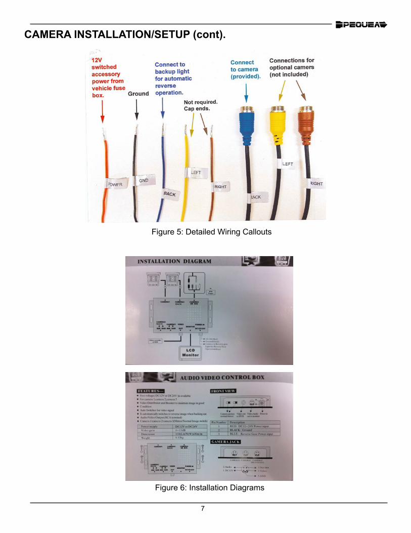
Figure 5: Detailed Wiring Callouts
Figure 6: Installation Diagrams
CAMERA INSTALLATION/SETUP (cont).
8
Field Transport
Never allow passengers on the spreader or the tractor.
Avoid tight turns to reduce the risk of loss of control or PTO shaft damage.
Remain fully aware of the width and length of the spreader in relation to the objects you are pass-ing, either stationary or moving.
Never travel at speeds over 10 MPH in the field when loaded.
For level or rolling terrain, tractor weight must be at least 50% of gross loaded spreader weight. For hilly terrain, road travel, or other adverse conditions, tractor weight must be equal to, or more than the gross loaded spreader weight.
Road Transport
Adhere to all suggestions for transport in the field listed above.
Follow all local regulations for moving agricultural equipment on public roads, especially those related to reflectors, SMV (slow moving vehicle) symbols and safety markers.
Be sure to use flashing lights at all times when transporting on public roads.
Slow down when turning to avoid instability and loss of control
Never travel at speeds over 20 MPH on the road.
TRANSPORT
9
General Operation
The apron and spinner functions on the Litter Spreader are driven hydraulically by the hydraulic pump run by the tractor PTO.
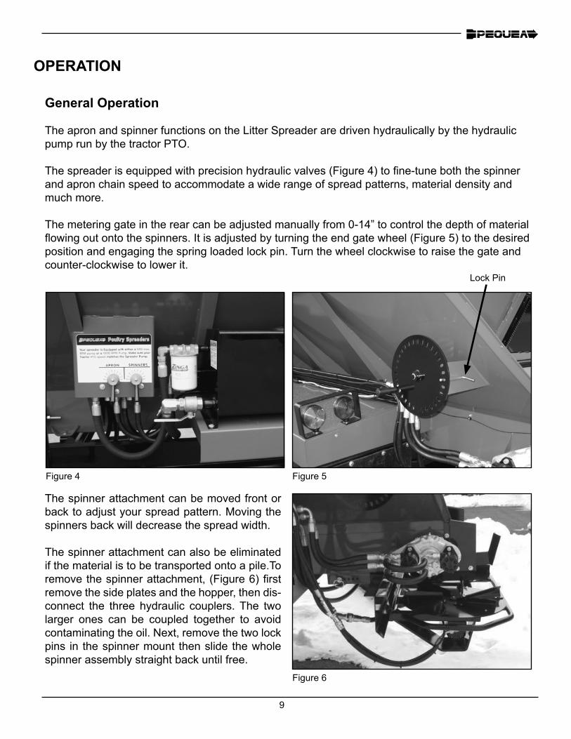
The spreader is equipped with precision hydraulic valves (Figure 4) to fine-tune both the spinner and apron chain speed to accommodate a wide range of spread patterns, material density and much more.
The metering gate in the rear can be adjusted manually from 0-14” to control the depth of material flowing out onto the spinners. It is adjusted by turning the end gate wheel (Figure 5) to the desired position and engaging the spring loaded lock pin. Turn the wheel clockwise to raise the gate and counter-clockwise to lower it.
Figure 4 Figure 5
Lock Pin
The spinner attachment can be moved front or back to adjust your spread pattern. Moving the spinners back will decrease the spread width.
The spinner attachment can also be eliminated if the material is to be transported onto a pile.To remove the spinner attachment, (Figure 6) first remove the side plates and the hopper, then dis-connect the three hydraulic couplers. The two larger ones can be coupled together to avoid contaminating the oil. Next, remove the two lock pins in the spinner mount then slide the whole spinner assembly straight back until free.
OPERATION
Figure 6
10
MAINTENANCE
General Maintenance
Check the litter spreader each time it is used for loose, bent, broken or missing parts or fasteners.
Never store material in the spreader in cold weather. The material could freeze against the sides and floor of the spreader and cause severe damage to the apron drive system.
Clean the excess manure off the sides of the spreader after each use. Manure is highly acidic so if there are any scratches in the paint it will immediately begin to rust.
Wheel & Tire Maintenance
Check wheel lug torque once a month or after each period of use. Wheel lugs should be torqued to 120 ft./lbs.
Check tire pressure before each period of use. Recommended tire pressure is stamped on the sidewall of each tire.
Wheel Bearing Maintenance
Remove the hub and check consistency of the wheel bearing grease at least once a year. If the grease is not the same consistency of fresh grease (either dry and caked or too thin) repack the bearings with fresh grease. Retighten the spindle nut to 25 ft. lbs. then back off one notch to insert cotter pin.
Grease Fitting Lubrication
The litter spreader is designed to require minimal lubrication. However, the importance of suffi-cient and proper lubrication cannot be over emphasized as it is the best insurance against unnec-essary repairs and will greatly increase the life and performance of the machine.
Lubricate all the grease fitting every six months or after 50 loads, whichever comes first. Be care-ful not to over grease the sealed bearings as too much grease could push out the seal and al-low dust or debris to contaminate the bearing. One half of a stroke from a manual grease pump should be sufficient. Be sure to wipe all the dust and debris away from the grease fitting before greasing. If it is not clean you may force some dirt into the bearing.
Non sealed (friction) grease points will not be damaged by over greasing and should be kept vis-ibly wet with grease.
11
Apron Chain Maintenance
Apply chain lube to the apron chain after each period of use to lubricate and prohibit rust.
The apron chain may need to be tightened periodically. 75 to 90 percent of the lower chain strand should be lying on the chain guides. The apron chain can be adjusted by using the apron tension-er bolts (Figure 8) on the front of the spreader. Be sure to adjust both sides equally so the chain is pulling straight.
MAINTENANCE
Figure 7
Figure 8
Hydraulic System Maintenance
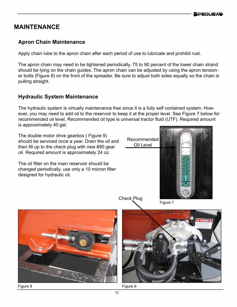
The hydraulic system is virtually maintenance free since it is a fully self contained system. How-ever, you may need to add oil to the reservoir to keep it at the proper level. See Figure 7 below for recommended oil level. Recommended oil type is universal tractor fluid (UTF). Required amount is approximately 40 gal.
Recommended Oil Level
The double motor drive gearbox ( Figure 9) should be serviced once a year. Drain the oil and then fill up to the check plug with new #90 gear oil. Required amount is approximately 24 oz.
The oil filter on the main reservoir should be changed periodically. use only a 10 micron filter designed for hydraulic oil.
Figure 9
Check Plug
12
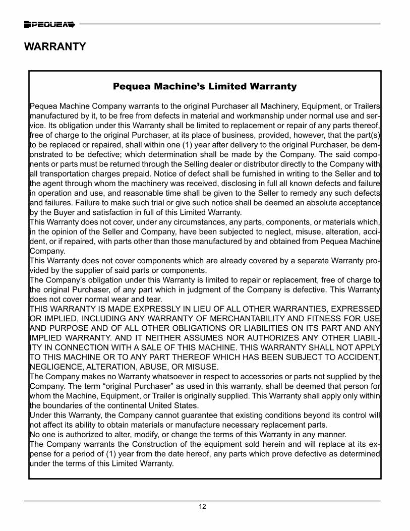
Pequea Machine’s Limited Warranty
Pequea Machine Company warrants to the original Purchaser all Machinery, Equipment, or Trailers manufactured by it, to be free from defects in material and workmanship under normal use and ser-vice. Its obligation under this Warranty shall be limited to replacement or repair of any parts thereof, free of charge to the original Purchaser, at its place of business, provided, however, that the part(s) to be replaced or repaired, shall within one (1) year after delivery to the original Purchaser, be dem-onstrated to be defective; which determination shall be made by the Company. The said compo-nents or parts must be returned through the Selling dealer or distributor directly to the Company with all transportation charges prepaid. Notice of defect shall be furnished in writing to the Seller and to the agent through whom the machinery was received, disclosing in full all known defects and failure in operation and use, and reasonable time shall be given to the Seller to remedy any such defects and failures. Failure to make such trial or give such notice shall be deemed an absolute acceptance by the Buyer and satisfaction in full of this Limited Warranty.This Warranty does not cover, under any circumstances, any parts, components, or materials which, in the opinion of the Seller and Company, have been subjected to neglect, misuse, alteration, acci-dent, or if repaired, with parts other than those manufactured by and obtained from Pequea Machine Company.This Warranty does not cover components which are already covered by a separate Warranty pro-vided by the supplier of said parts or components.The Company’s obligation under this Warranty is limited to repair or replacement, free of charge to the original Purchaser, of any part which in judgment of the Company is defective. This Warranty does not cover normal wear and tear.THIS WARRANTY IS MADE EXPRESSLY IN LIEU OF ALL OTHER WARRANTIES, EXPRESSED OR IMPLIED, INCLUDING ANY WARRANTY OF MERCHANTABILITY AND FITNESS FOR USE AND PURPOSE AND OF ALL OTHER OBLIGATIONS OR LIABILITIES ON ITS PART AND ANY IMPLIED WARRANTY. AND IT NEITHER ASSUMES NOR AUTHORIZES ANY OTHER LIABIL-ITY IN CONNECTION WITH A SALE OF THIS MACHINE. THIS WARRANTY SHALL NOT APPLY TO THIS MACHINE OR TO ANY PART THEREOF WHICH HAS BEEN SUBJECT TO ACCIDENT, NEGLIGENCE, ALTERATION, ABUSE, OR MISUSE.The Company makes no Warranty whatsoever in respect to accessories or parts not supplied by the Company. The term “original Purchaser” as used in this warranty, shall be deemed that person for whom the Machine, Equipment, or Trailer is originally supplied. This Warranty shall apply only within the boundaries of the continental United States.Under this Warranty, the Company cannot guarantee that existing conditions beyond its control will not affect its ability to obtain materials or manufacture necessary replacement parts.No one is authorized to alter, modify, or change the terms of this Warranty in any manner.The Company warrants the Construction of the equipment sold herein and will replace at its ex-pense for a period of (1) year from the date hereof, any parts which prove defective as determined under the terms of this Limited Warranty.
WARRANTY

13
NOTES

14


®®
200 Jalyn Drive P.O. Box 399
New Holland PA 17557
Phone: 717-354-4343Fax: 717-354-8843
E-mail: [email protected]


