NAUTICAL RESEARCH JOURNAL 45 Liverpool-Class Lifeboat, A RNLI 1945 lifeboat at 1:18 scale: A Call for Updating the Dockyard-style of Modeling . . . . . by Hubert Mallet Translated by François Fougerat Figure 1. The aft section of l’Aurore. All photographs by the author. Once his latest “masterpiece”, the fruit of many years of labor, has been safely put away under glass, a modeler, without fail, will ask himself: “and now, what will be my next project?” A difficult question if one considers that this latest model was only the nth version of a too long series and that one may rightfully wonder about the interest of doing, one more time, something others have already accomplished, often with more talent. Having completed the lengthy and la- borious construction of a model of the aft section of l’Aurore (Figure 1), I was contem- plating the appropriateness of this way of thinking. To launch into a more thorough adventure combining historical research, monograph, and model construction would mean facing the unknown, giving up the quiet solitude of the modeler as well as the
Transcript
NAUTICAL RESEARCH JOURNAL 45
Liverpool-Class Lifeboat, A RNLI 1945lifeboat at 1:18 scale: A Call for Updating
the Dockyard-style of Modeling. . . . .
by Hubert Mallet
Translated by François Fougerat
Figure 1. The aft section of l’Aurore. All photographs by theauthor.
Once his latest “masterpiece”, thefruit of many years of labor, has been safelyput away under glass, a modeler, withoutfail, will ask himself: “and now, what will bemy next project?” A difficult question if oneconsiders that this latest model was only thenth version of a too long series and that onemay rightfully wonder about the interest ofdoing, one more time, something othershave already accomplished, often with moretalent.
Having completed the lengthy and la-borious construction of a model of the aftsection of l’Aurore (Figure 1), I was contem-plating the appropriateness of this way ofthinking. To launch into a more thoroughadventure combining historical research,monograph, and model construction wouldmean facing the unknown, giving up thequiet solitude of the modeler as well as the
Vol. 60, No 1 SPRING 201546
limited usage of the techniques he has mas-tered.
On the occasion of a trip to Englandorganized by the l’Association des Amis duMusée National de la Marine, a visit to theChatham Historic Dockyard enabled us todiscover an important collection of perfectlyrestored all-weather boats of the Royal Na-tional Lifeboat Institution, including GraceDarling, a 1945 Liverpool-class lifeboat withinimitable charm, and very British. My sub-ject had been found. (Figure 2)
Developing Documentary Research
Naively, one may believe that docu-mentary resources concerning a 1945 boatwould be readily available, but that would beforgetting many factors, such as a degree ofindifference in an organization which, likemany others, may have little interest in itsown archives, or the inertia of an archivist,poorly motivated because of imminent re-tirement. Be that as it may, like the rod fish-
erman, the modeler will need to turn overmany stones before finding the requiredworms; furthermore, this research could bethe opportunity to revive some old memo-ries of the English language.
Anecdotally, after two years of notvery fruitful research, I learned from a RoyalNational Lifeboat Institution site that therestoration of the boat Harris had been en-trusted to an Englishman running a boat-yard in France in the city of Sens, the SimonEvans International Shipyard. This enabledme to meet with Mr. Simon Evans, a manpassionately interested in lifeboats and theowner of an extensive collection of thesecraft, who was less than sixty miles from myhome.
As a final task before producing thedocumentation, it was important to ascer-tain the condition of the prototype at a givendate. Indeed, in the course of its life everyboat undergoes a series of changes. It, there-fore, is important to specify the date whichit represents; in this instance the first ver-
Figure 2. Grace Darling at Chatham Historic Dockyard.
NAUTICAL RESEARCH JOURNAL 47
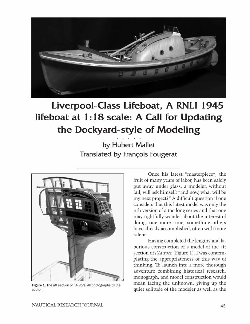
Figure 3. Hull structural plans constructed using AutoCAD.
sion of the Liverpool-class lifeboat with avery specific original power system. Once allthese elements had been determined, it wasfinally possible to start the drawings of theboat and then the construction of themodel. (Figure 3)
Learning and Understanding the
Computerized Tool
An unavoidable tool, computer-aideddesign (CAD) has become readily available.It is no longer a gadget but a real tool that
Figure 4. Three-dimensional view of the hull, showing method for determination of a frame.
Vol. 60, No 1 SPRING 201548
Figure 6. CAD rendering of the after bulkhead arrangement, together with a delineation of the expanded bulkhead.
Figure 5. Body plan.
allows understanding of objects in three-di-mensional space. Manual drafting used tolimit our perspective to three plane sections(horizontal, transverse and longitudinal);therefore, numerous elements such asframes were only comprehensible by puttingtogether a number of points from each ofthese dimensions.
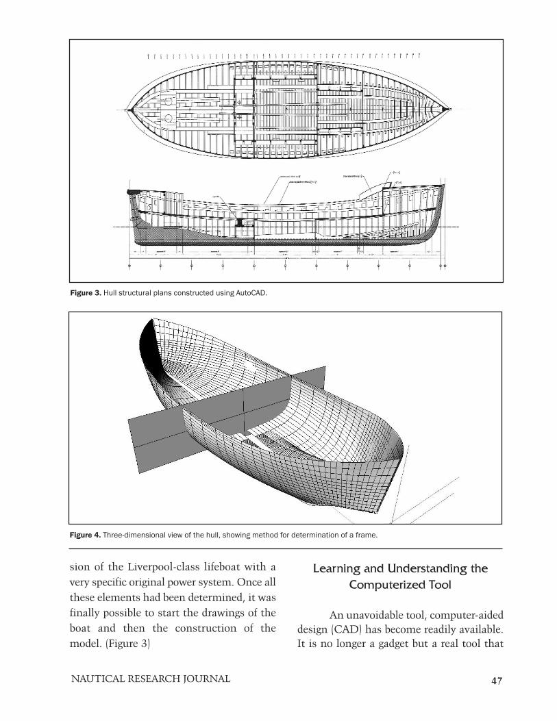
The main benefit of CAD is to makethe three-dimensional view immediatelyavailable. Within the scope of the study of amodel, the shape of the hull can be deter-mined, planked inside or outside, with thehelp of many tools that allow verification ofthe fairness of the surface. (Figure 4)
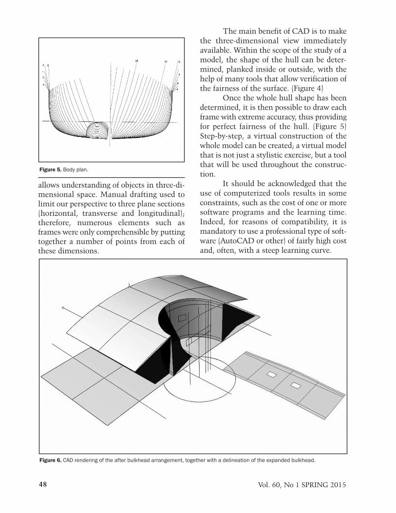
Once the whole hull shape has beendetermined, it is then possible to draw eachframe with extreme accuracy, thus providingfor perfect fairness of the hull. (Figure 5)Step-by-step, a virtual construction of thewhole model can be created; a virtual modelthat is not just a stylistic exercise, but a toolthat will be used throughout the construc-tion.
It should be acknowledged that theuse of computerized tools results in someconstraints, such as the cost of one or moresoftware programs and the learning time.Indeed, for reasons of compatibility, it ismandatory to use a professional type of soft-ware (AutoCAD or other) of fairly high costand, often, with a steep learning curve.
NAUTICAL RESEARCH JOURNAL 49
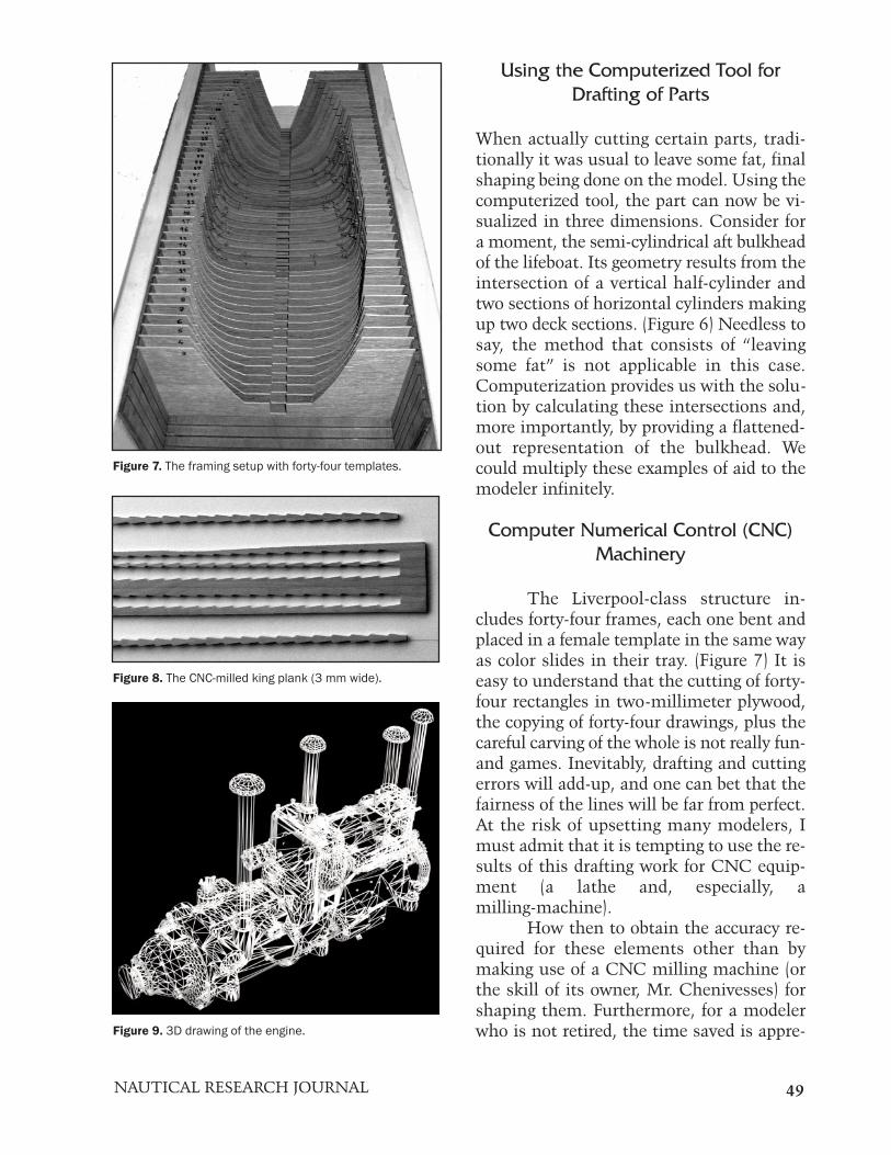
Figure 7. The framing setup with forty-four templates.
Figure 8. The CNC-milled king plank (3 mm wide).
Figure 9. 3D drawing of the engine.
Using the Computerized Tool for
Drafting of Parts
When actually cutting certain parts, tradi-tionally it was usual to leave some fat, finalshaping being done on the model. Using thecomputerized tool, the part can now be vi-sualized in three dimensions. Consider fora moment, the semi-cylindrical aft bulkheadof the lifeboat. Its geometry results from theintersection of a vertical half-cylinder andtwo sections of horizontal cylinders makingup two deck sections. (Figure 6) Needless tosay, the method that consists of “leavingsome fat” is not applicable in this case.Computerization provides us with the solu-tion by calculating these intersections and,more importantly, by providing a flattened-out representation of the bulkhead. Wecould multiply these examples of aid to themodeler infinitely.
Computer Numerical Control (CNC)
Machinery
The Liverpool-class structure in-cludes forty-four frames, each one bent andplaced in a female template in the same wayas color slides in their tray. (Figure 7) It iseasy to understand that the cutting of forty-four rectangles in two-millimeter plywood,the copying of forty-four drawings, plus thecareful carving of the whole is not really fun-and games. Inevitably, drafting and cuttingerrors will add-up, and one can bet that thefairness of the lines will be far from perfect.At the risk of upsetting many modelers, Imust admit that it is tempting to use the re-sults of this drafting work for CNC equip-ment (a lathe and, especially, amilling-machine).
How then to obtain the accuracy re-quired for these elements other than bymaking use of a CNC milling machine (orthe skill of its owner, Mr. Chenivesses) forshaping them. Furthermore, for a modelerwho is not retired, the time saved is appre-
Vol. 60, No 1 SPRING 201550
Figure 12. Diagram illustrating the UV flashing of the poly-mer to make the engine block.
Figure 10. Rendering of the engine cut into slices. To help un-derstand the concept better, the thickness of the slices hasbeen increased considerably.
Figure 11. Diagrammatic rendering of the 3D printer ma-chinery. Courtesy of Societé IDO Création.
ciable, especially in the case of a particularlytedious and uninteresting job.
In order to get a jump on potentialcriticisms, it should be noted that the use of
such tools obviously should be limited towhen it is advantageous to use these ma-chines. Their use should be reserved for themost difficult shaping jobs requiring perfectaccuracy, such as a king plank, or those thatare very specific, like a fashion piece. (Figure 8)
Stereo-Lithography
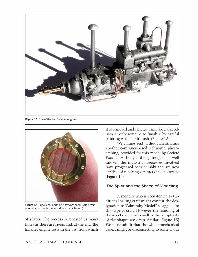
There comes a time when even themost skilled modeler can only give up. TheLiverpool-class lifeboat is fitted with two en-gines that are less than four centimeters (1.6inches) long at 1:18 scale. How can these bereproduced at that scale when their manyaccessories measure only tenths of a mil-limeter? Stereo-lithography, or 3D-printing,offers the solution.
As a first step, the engine must bedrafted as a three-dimensional computerizeddrawing and the information passed on to aspecialist possessing the necessary equip-ment, in this case, Societé IDO Création.(Figure 9) To the purists who may want toaccuse us of cheating, I must point out thatthese drawings required more than 200hours of labor, and include 464 poly-surfacesand 181 simple surfaces. The computerizeddrawing of the engine is then broken downby the computer into horizontal layers six-teen microns thick. The final shape is there-fore made up of a stack of these layers.(Figure 10) The machine (Figure 11) in-cludes:
• A vat containing a UV-sensitivephotopolymer• At the base is a mobile platform thatmoves vertically under computer control• A mobile UV light that can movealong the X and Y axes, also under computercontrol.
The UV light flashes the first layer of the en-gine model and causes it to harden. (Figure12) At the end of the operation, the platformis lowered by sixteen microns, the thickness
NAUTICAL RESEARCH JOURNAL 51
Figure 13. One of the two finished engines.
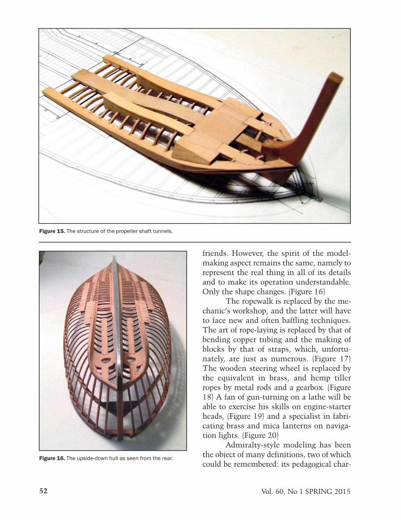
Figure 14. Functional porthole hardware constructed fromphoto-etched parts (outside diameter is 14 mm).
of a layer. The process is repeated as manytimes as there are layers and, at the end, thefinished engine rests in the vat, from which
it is removed and cleaned using special prod-ucts. It only remains to finish it by carefulpainting with an airbrush. (Figure 13)
We cannot end without mentioninganother computer-based technique: photo-etching, provided for this model by SocietéExcela. Although the principle is wellknown, the industrial processes involvedhave progressed considerably and are nowcapable of reaching a remarkable accuracy.(Figure 14)
The Spirit and the Shape of Modeling
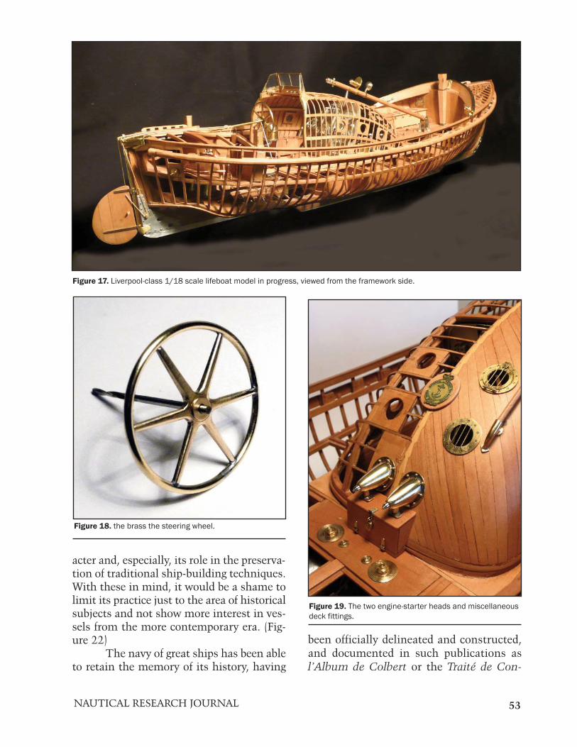
A modeler who is accustomed to tra-ditional sailing craft might contest the des-ignation of “Admiralty Model” as applied tothis type of craft. However, the handling ofthe wood structure as well as the complexityof the shapes are often similar. (Figure 15)We must admit that the whole mechanicalaspect might be disconcerting to some of our
Vol. 60, No 1 SPRING 201552
Figure 16. The upside-down hull as seen from the rear.
Figure 15. The structure of the propeller shaft tunnels.
friends. However, the spirit of the model-making aspect remains the same, namely torepresent the real thing in all of its detailsand to make its operation understandable.Only the shape changes. (Figure 16)
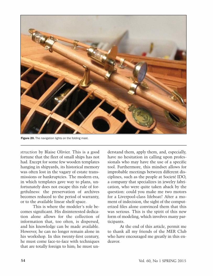
The ropewalk is replaced by the me-chanic’s workshop, and the latter will haveto face new and often baffling techniques.The art of rope-laying is replaced by that ofbending copper tubing and the making ofblocks by that of straps, which, unfortu-nately, are just as numerous. (Figure 17)The wooden steering wheel is replaced bythe equivalent in brass, and hemp tillerropes by metal rods and a gearbox. (Figure18) A fan of gun-turning on a lathe will beable to exercise his skills on engine-starterheads, (Figure 19) and a specialist in fabri-cating brass and mica lanterns on naviga-tion lights. (Figure 20)
Admiralty-style modeling has beenthe object of many definitions, two of whichcould be remembered: its pedagogical char-
NAUTICAL RESEARCH JOURNAL 53
Figure 18. the brass the steering wheel.
Figure 19. The two engine-starter heads and miscellaneousdeck fittings.
Figure 17. Liverpool-class 1/18 scale lifeboat model in progress, viewed from the framework side.
acter and, especially, its role in the preserva-tion of traditional ship-building techniques.With these in mind, it would be a shame tolimit its practice just to the area of historicalsubjects and not show more interest in ves-sels from the more contemporary era. (Fig-ure 22)
The navy of great ships has been ableto retain the memory of its history, having
been officially delineated and constructed,and documented in such publications asl’Album de Colbert or the Traité de Con-
Vol. 60, No 1 SPRING 201554
struction by Blaise Olivier. This is a goodfortune that the fleet of small ships has nothad. Except for some few wooden templateshanging in shipyards, its historical memorywas often lost in the vagary of estate trans-missions or bankruptcies. The modern era,in which templates gave way to plans, un-fortunately does not escape this rule of for-getfulness: the preservation of archivesbecomes reduced to the period of warranty,or to the available linear shelf space.
This is where the modeler’s role be-comes significant. His disinterested dedica-tion alone allows for the collection ofinformation that, too often, is dispersed,and his knowledge can be made available.However, he can no longer remain alone inhis workshop. In this twenty-first century,he must come face-to-face with techniquesthat are totally foreign to him; he must un-
derstand them, apply them, and, especially,have no hesitation in calling upon profes-sionals who may have the use of a specifictool. Furthermore, this mindset allows forimprobable meetings between different dis-ciplines, such as the people at Societé IDO,a company that specializes in jewelry fabri-cation, who were quite taken aback by thequestion: could you make me two motorsfor a Liverpool-class lifeboat? After a mo-ment of indecision, the sight of the comput-erized files alone convinced them that thiswas serious. This is the spirit of this newform of modeling, which involves many par-ticipants.
At the end of this article, permit meto thank all my friends of the MER Clubwho have encouraged me greatly in this en-deavor.
Figure 20. The navigation lights on the folding mast.