37
Load Rating Atypical Concrete Bridges with BrR 2018 RADBUG Meeting Boise, Idaho Mike Briggs, PE, SE Allie Wagner, PE HNTB Corporation - Kansas City, MO
Load Rating Atypical Concrete Bridges with BrR
2018 RADBUG Meeting
Boise, Idaho
Mike Briggs, PE, SE
Allie Wagner, PE
HNTB Corporation - Kansas City, MO
Overview
• Complex Slab Systems using Simplified Line Analyses• Edge-Supported Skewed Slab
• Illinois Bulletin Slab (IBS) Bridges
• Unsupported Structures using “Static Rating Factor” Models• Filled-Spandrel Arches
• Conclusions
Edge-Supported Skewed Slab
Edge-Supported Skewed Slab
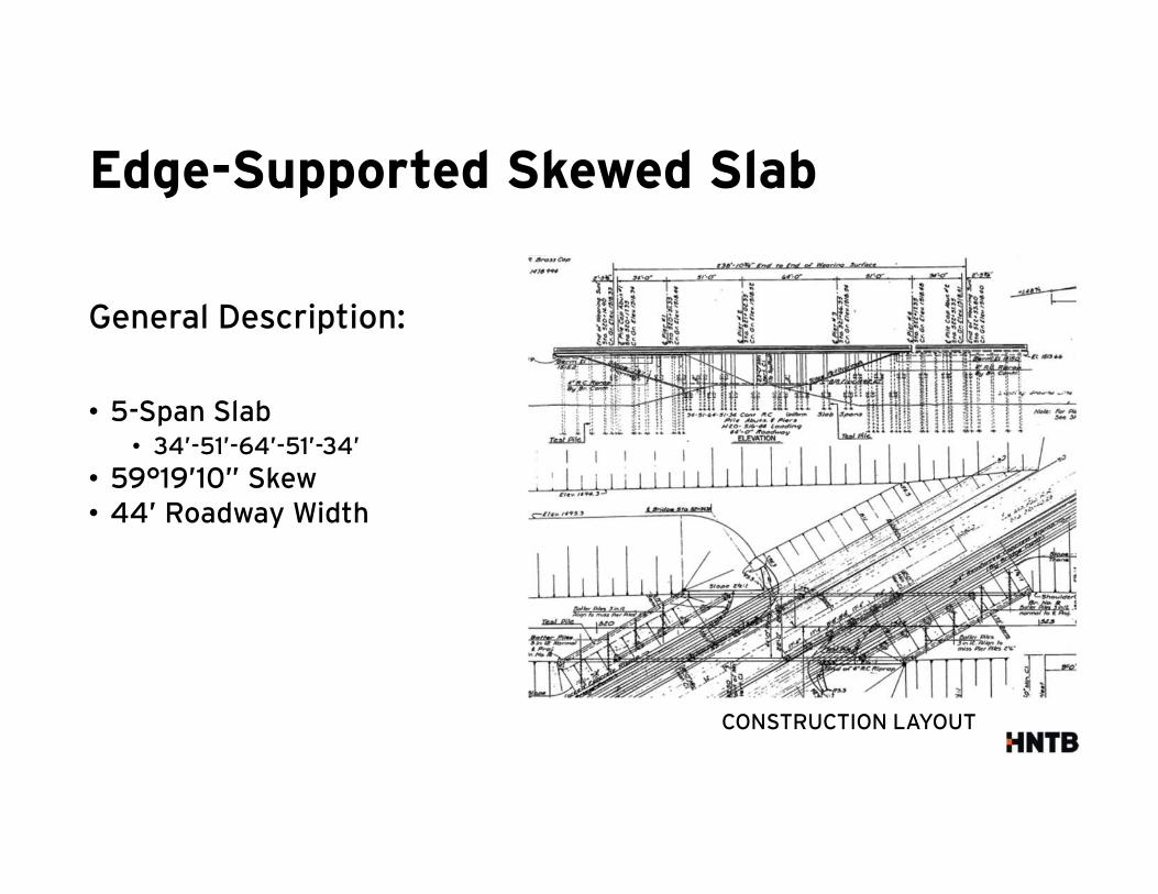
General Description:
• 5-Span Slab• 34’-51’-64’-51’-34’
• 59°19’10” Skew• 44’ Roadway Width
CONSTRUCTION LAYOUT
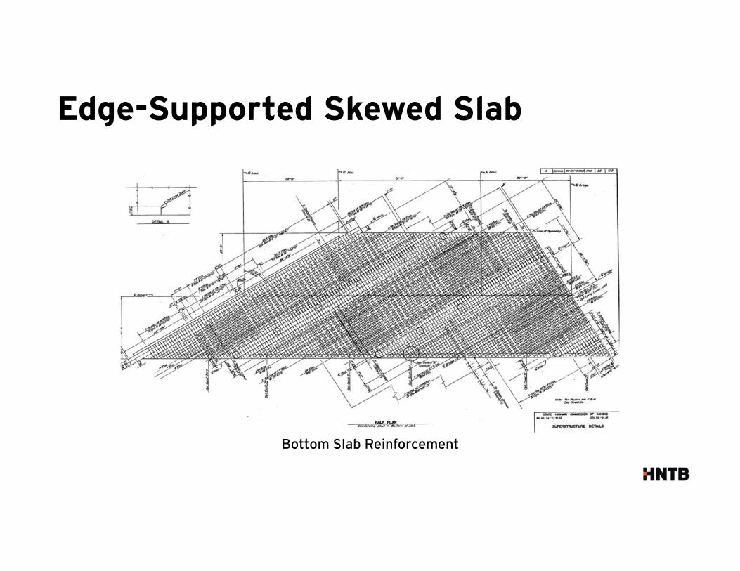
Bottom Slab Reinforcement
Edge-Supported Skewed Slab
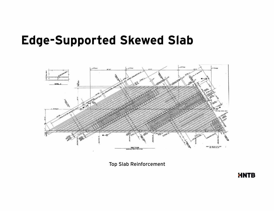
Top Slab Reinforcement
Edge-Supported Skewed Slab
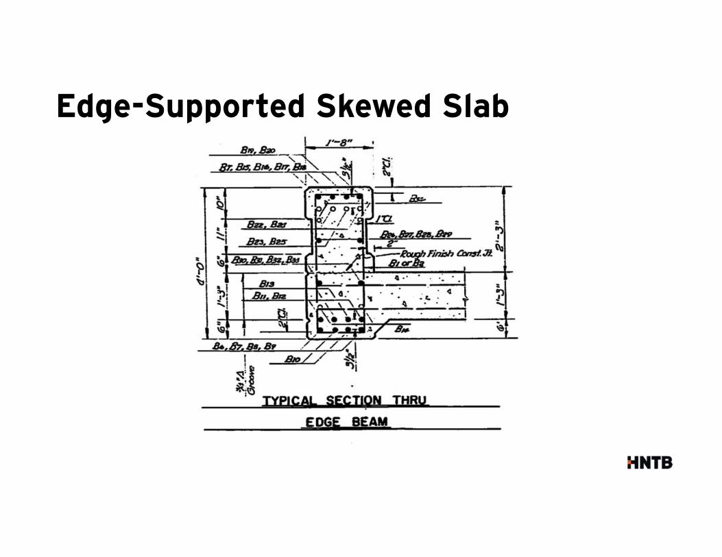
Top Slab Reinforcement
Edge-Supported Skewed Slab
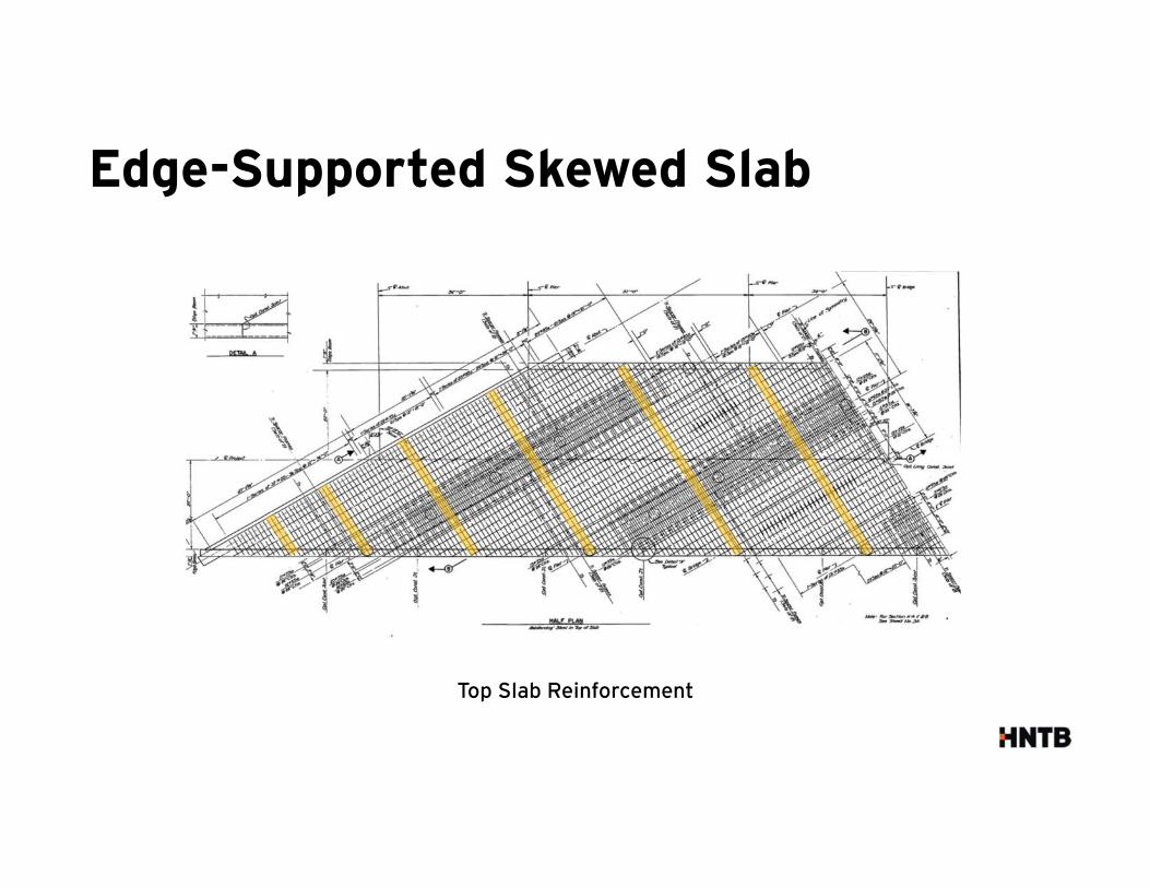
Top Slab Reinforcement
Edge-Supported Skewed Slab
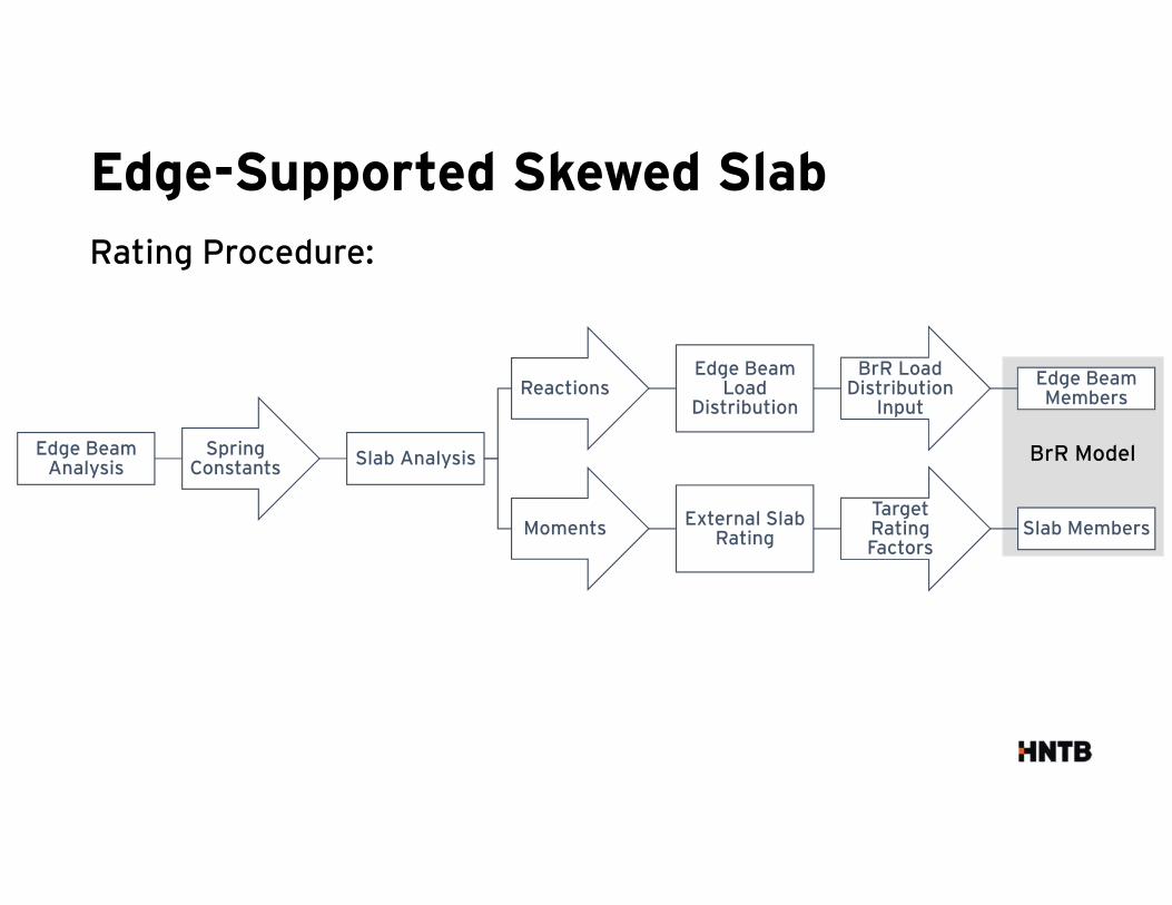
Rating Procedure:
Edge Beam Analysis
Spring Constants
Slab Analysis
ReactionsEdge Beam
Load Distribution
BrR Load Distribution
Input
Edge Beam Members
Moments External Slab Rating
Target Rating Factors
Slab Members
Edge-Supported Skewed Slab
BrR Model
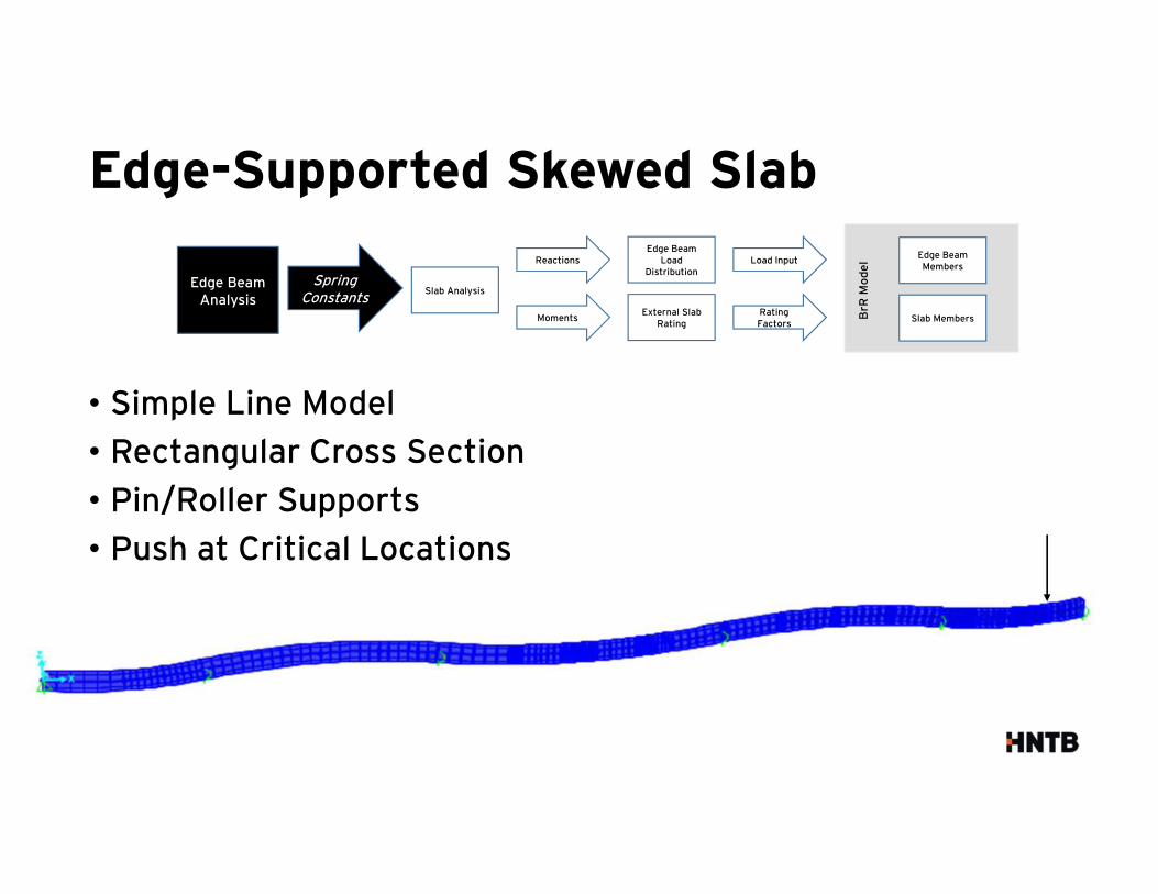
• Simple Line Model
• Rectangular Cross Section
• Pin/Roller Supports
• Push at Critical Locations
Edge-Supported Skewed Slab
Spring Constants
Edge Beam Analysis
Reactions
Slab Analysis
Moments
Load InputEdge Beam
Load Distribution
Rating Factors
External Slab Rating
Edge Beam Members
Slab MembersBrR
Mo
de
l
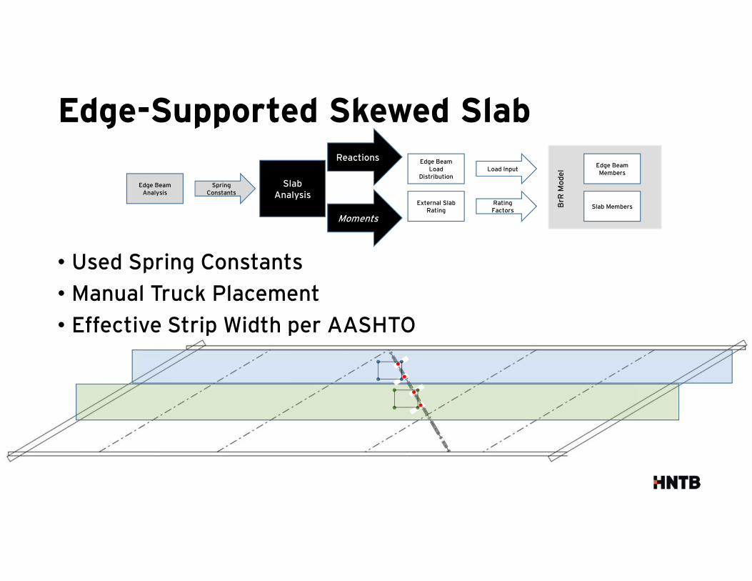
• Used Spring Constants
• Manual Truck Placement
• Effective Strip Width per AASHTO
Edge-Supported Skewed Slab
Spring Constants
Edge Beam Analysis
Reactions
Slab Analysis
Moments
Load InputEdge Beam
Load Distribution
Rating Factors
External Slab Rating
Edge Beam Members
Slab MembersBrR
Mo
de
l
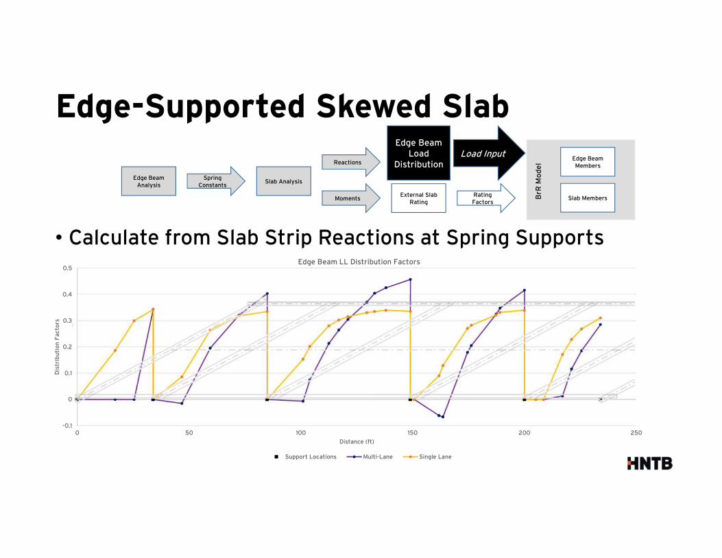
• Calculate from Slab Strip Reactions at Spring Supports
Edge-Supported Skewed Slab
-0.1
0
0.1
0.2
0.3
0.4
0.5
0 50 100 150 200 250
Dis
trib
uti
on
Fa
cto
rs
Distance (ft)
Edge Beam LL Distribution Factors
Support Locations Multi-Lane Single Lane
Spring Constants
Edge Beam Analysis
Reactions
Slab Analysis
Moments
Load InputEdge Beam
Load Distribution
Rating Factors
External Slab Rating
Edge Beam Members
Slab MembersBrR
Mo
de
l
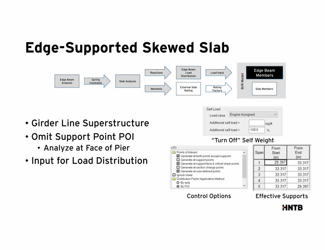
• Girder Line Superstructure
• Omit Support Point POI• Analyze at Face of Pier
• Input for Load Distribution
Edge-Supported Skewed Slab
Effective SupportsControl Options
“Turn Off” Self Weight
Spring Constants
Edge Beam Analysis
Reactions
Slab Analysis
Moments
Load InputEdge Beam
Load Distribution
Rating Factors
External Slab Rating
Edge Beam Members
Slab MembersBrR
Mo
de
l
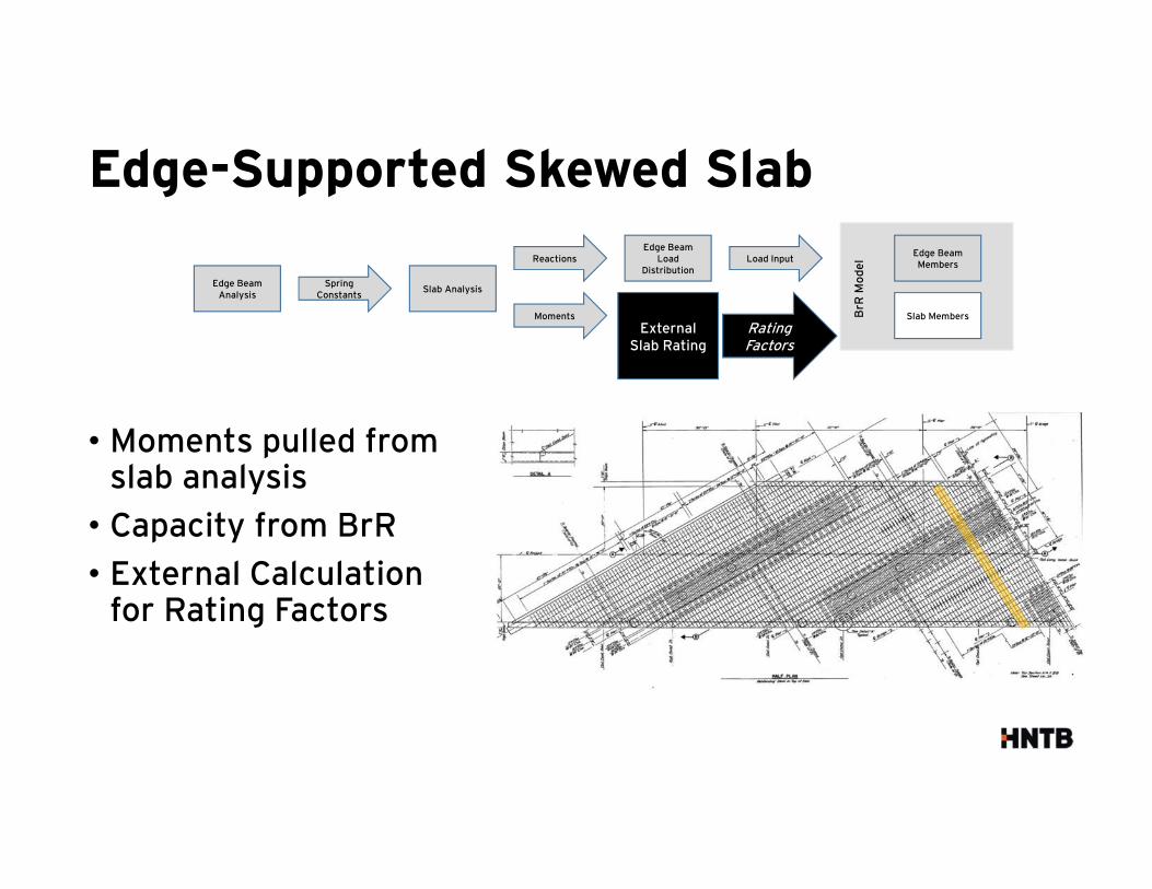
• Moments pulled from slab analysis
• Capacity from BrR
• External Calculation for Rating Factors
Edge-Supported Skewed Slab
Spring Constants
Edge Beam Analysis
Reactions
Slab Analysis
Moments
Load InputEdge Beam
Load Distribution
Rating Factors
External Slab Rating
Edge Beam Members
Slab MembersBrR
Mo
de
l
Edge-Supported Skewed Slab
Spring Constants
Edge Beam Analysis
Reactions
Slab Analysis
Moments
Load InputEdge Beam
Load Distribution
Rating Factors
External Slab Rating
Edge Beam Members
Slab MembersBrR
Mo
de
l
Edge-Supported Skewed Slab
Spring Constants
Edge Beam Analysis
Reactions
Slab Analysis
Moments
Load InputEdge Beam
Load Distribution
Rating Factors
External Slab Rating
Edge Beam Members
Slab MembersBrR
Mo
de
l
Illinois Bulletin Slab (IBS) Bridges
Illinois Bulletin Slab (IBS) Bridges
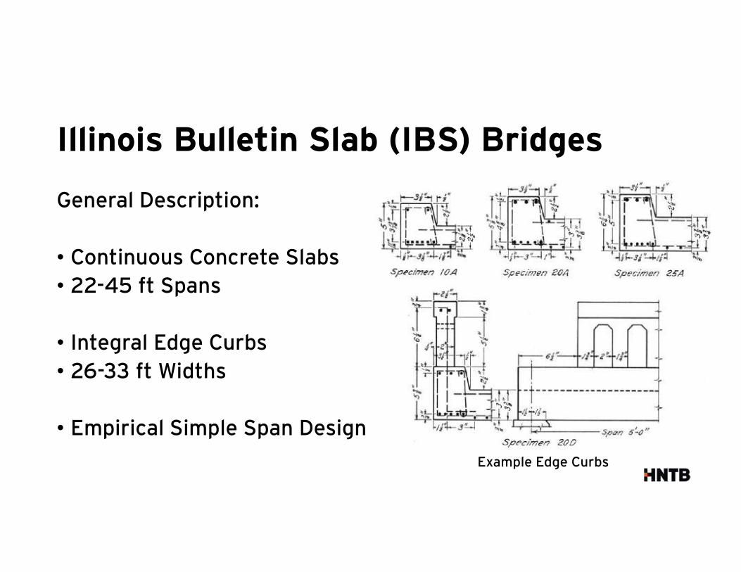
General Description:
• Continuous Concrete Slabs
• 22-45 ft Spans
• Integral Edge Curbs
• 26-33 ft Widths
• Empirical Simple Span Design
Example Edge Curbs
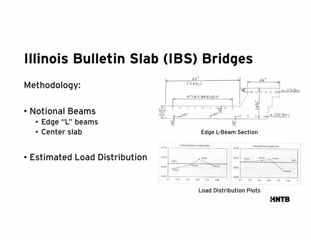
Edge L-Beam Section
Illinois Bulletin Slab (IBS) Bridges
Methodology:
• Notional Beams• Edge “L” beams
• Center slab
• Estimated Load Distribution
Load Distribution Plots
Illinois Bulletin Slab (IBS) Bridges
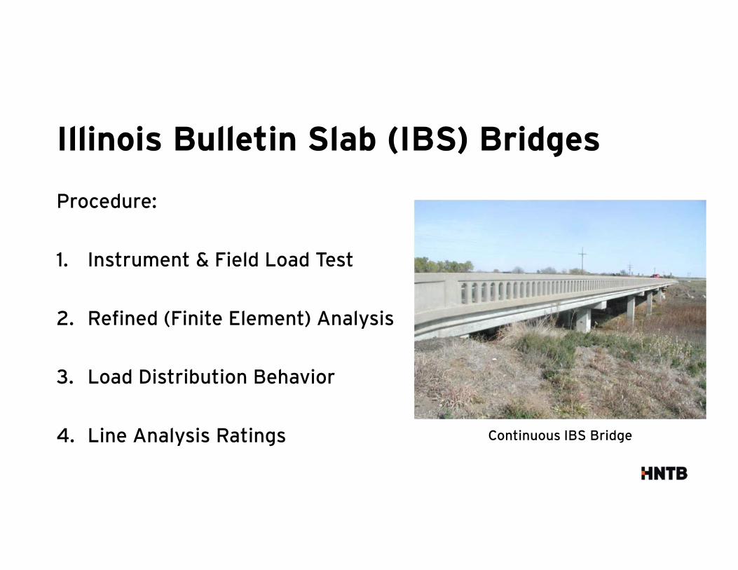
Procedure:
1. Instrument & Field Load Test
2. Refined (Finite Element) Analysis
3. Load Distribution Behavior
4. Line Analysis Ratings Continuous IBS Bridge
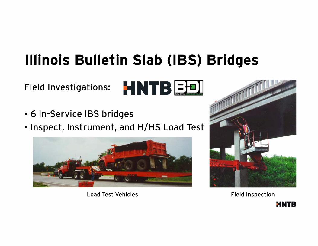
Illinois Bulletin Slab (IBS) Bridges
Field Investigations:
• 6 In-Service IBS bridges
• Inspect, Instrument, and H/HS Load Test
Field InspectionLoad Test Vehicles
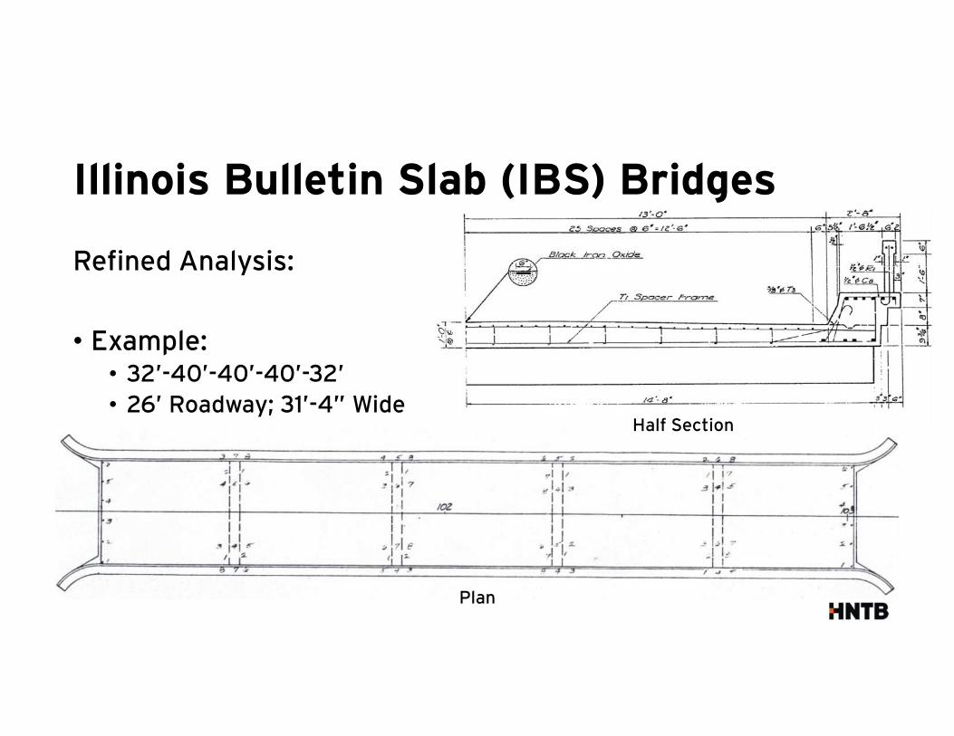
Illinois Bulletin Slab (IBS) Bridges
Refined Analysis:
• Example:• 32’-40’-40’-40’-32’
• 26’ Roadway; 31’-4” Wide
Plan
Half Section
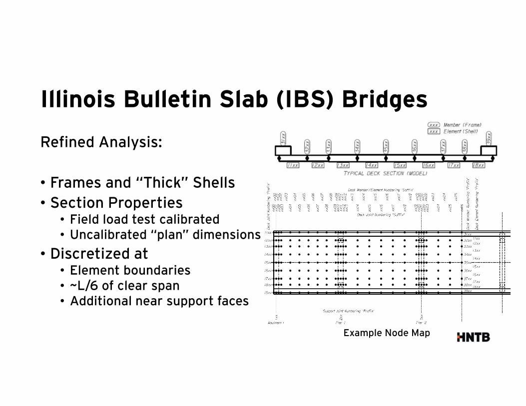
Illinois Bulletin Slab (IBS) Bridges
Refined Analysis:
• Frames and “Thick” Shells
• Section Properties• Field load test calibrated• Uncalibrated “plan” dimensions
• Discretized at• Element boundaries• ~L/6 of clear span• Additional near support faces
Example Node Map
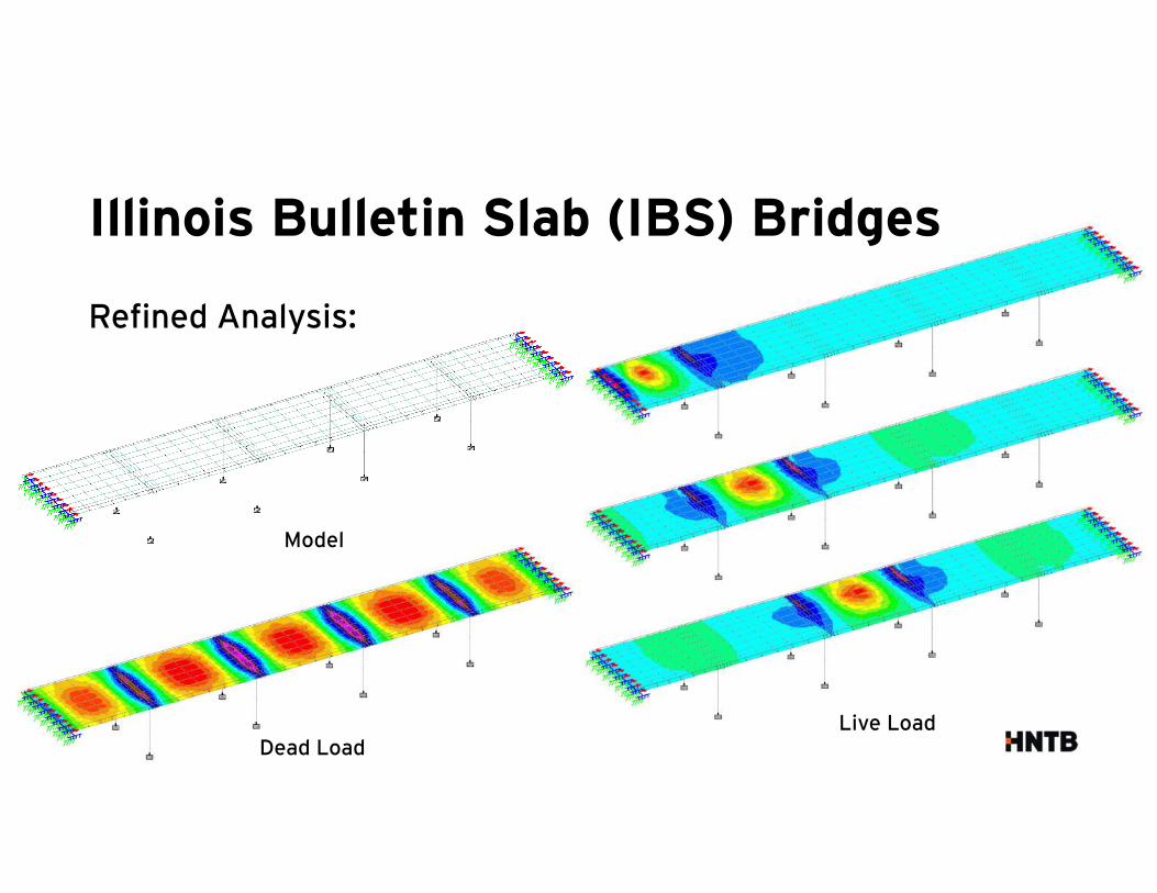
Refined Analysis:
Model
Dead LoadLive Load
Illinois Bulletin Slab (IBS) Bridges
Illinois Bulletin Slab (IBS) Bridges
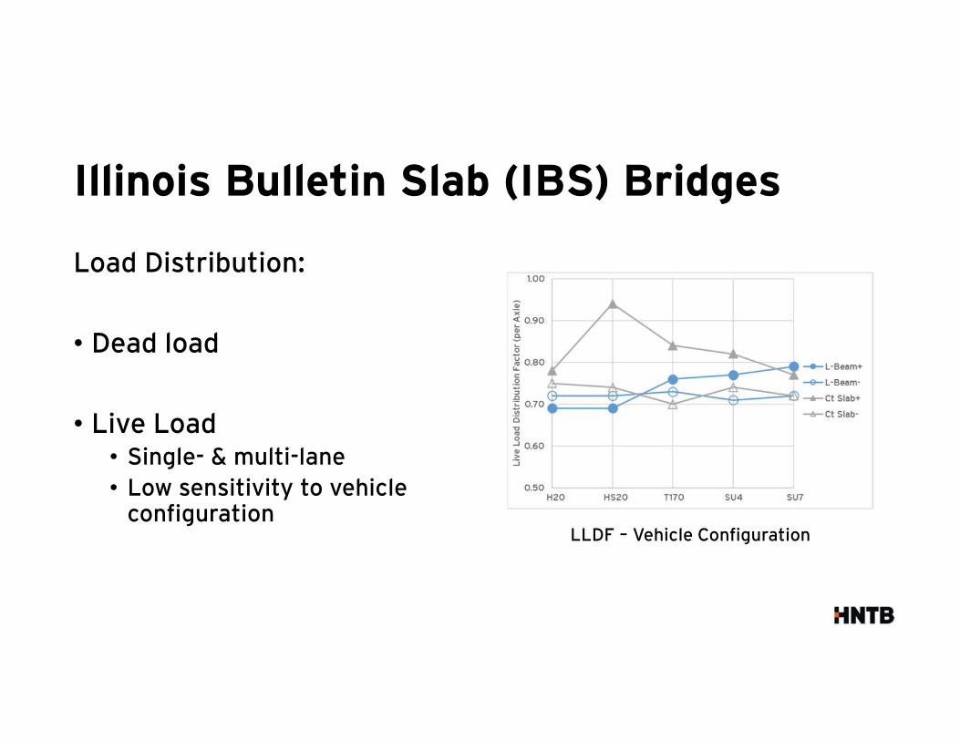
Load Distribution:
• Dead load
• Live Load• Single- & multi-lane
• Low sensitivity to vehicle configuration
LLDF – Vehicle Configuration
Illinois Bulletin Slab (IBS) Bridges
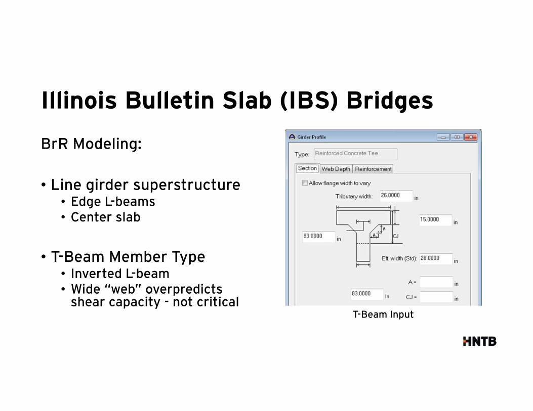
BrR Modeling:
• Line girder superstructure• Edge L-beams• Center slab
• T-Beam Member Type• Inverted L-beam• Wide “web” overpredicts
shear capacity - not criticalT-Beam Input
Illinois Bulletin Slab (IBS) Bridges
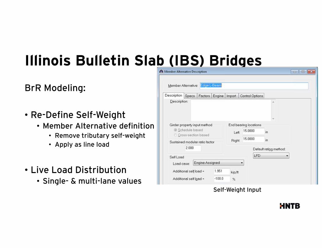
BrR Modeling:
• Re-Define Self-Weight• Member Alternative definition
• Remove tributary self-weight
• Apply as line load
• Live Load Distribution• Single- & multi-lane values
Self-Weight Input
Illinois Bulletin Slab (IBS) Bridges
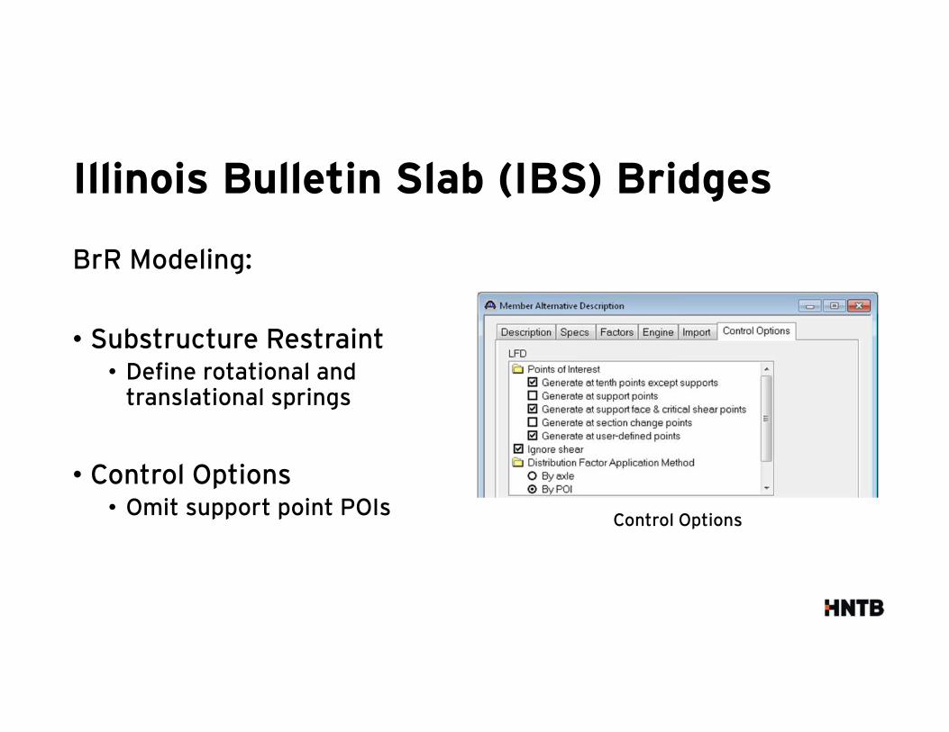
BrR Modeling:
• Substructure Restraint• Define rotational and
translational springs
• Control Options• Omit support point POIs
Control Options

Filled-Spandrel Arches
Filled-Spandrel Arches
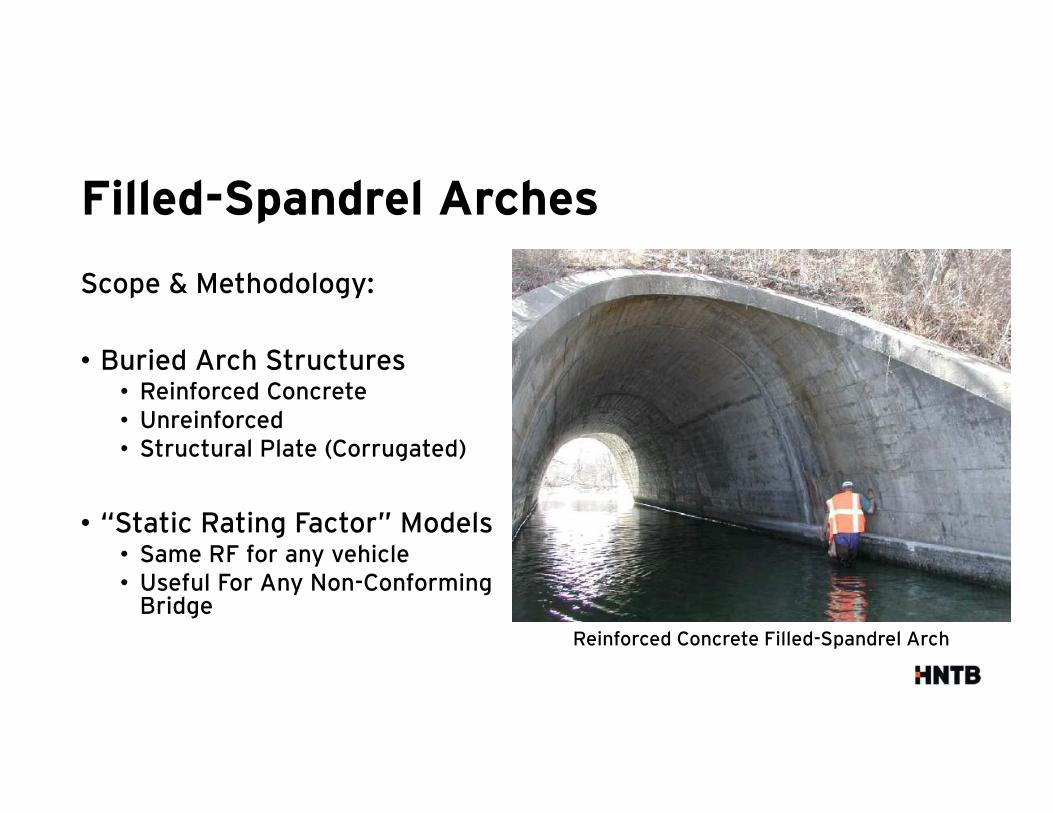
Scope & Methodology:
• Buried Arch Structures• Reinforced Concrete• Unreinforced• Structural Plate (Corrugated)
• “Static Rating Factor” Models• Same RF for any vehicle• Useful For Any Non-Conforming
Bridge
Reinforced Concrete Filled-Spandrel Arch
Filled-Spandrel Arches
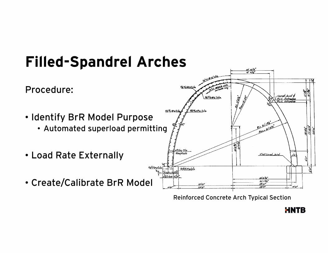
Procedure:
• Identify BrR Model Purpose• Automated superload permitting
• Load Rate Externally
• Create/Calibrate BrR Model
Reinforced Concrete Arch Typical Section
Filled-Spandrel Arches
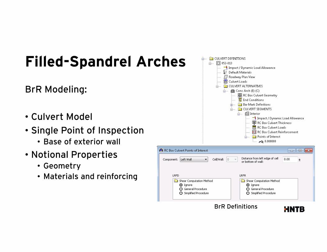
BrR Modeling:
• Culvert Model
• Single Point of Inspection• Base of exterior wall
• Notional Properties• Geometry
• Materials and reinforcing
BrR Definitions
Filled-Spandrel Arches
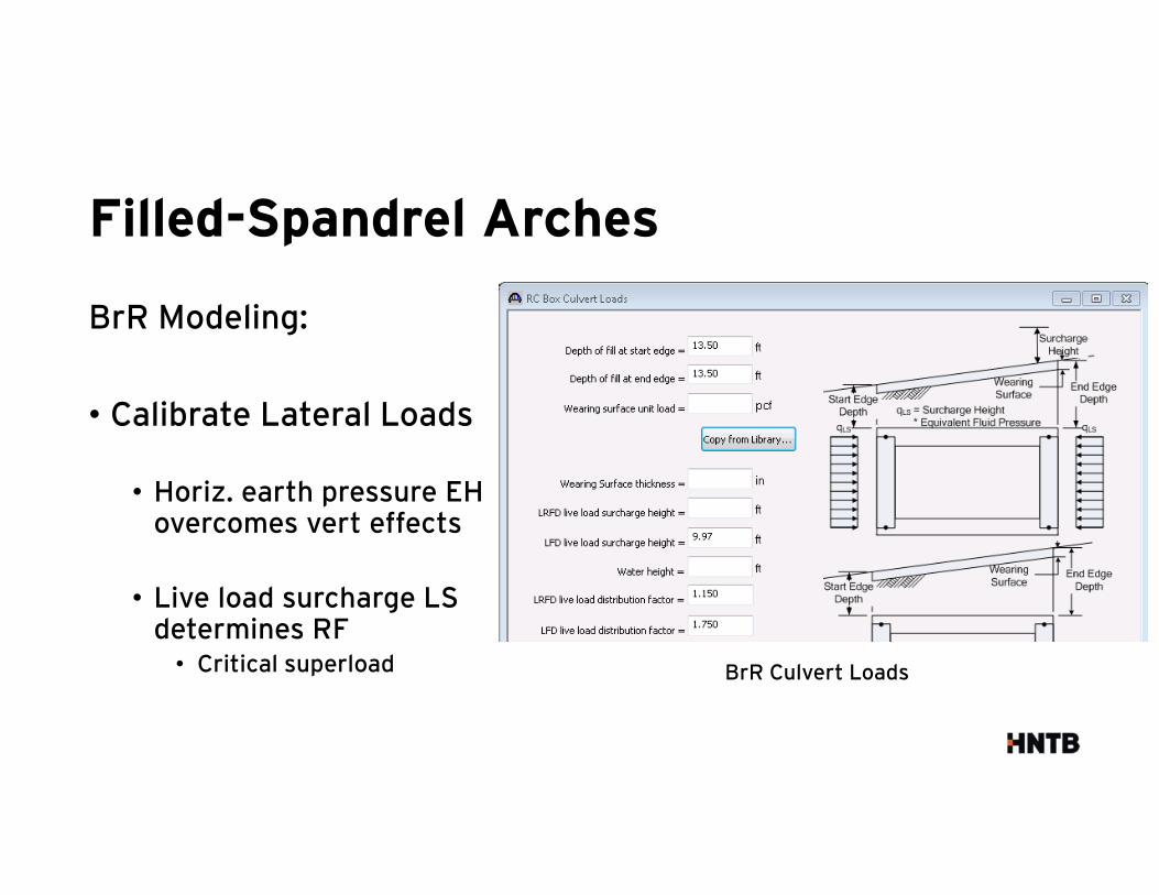
BrR Modeling:
• Calibrate Lateral Loads
• Horiz. earth pressure EH overcomes vert effects
• Live load surcharge LS determines RF• Critical superload BrR Culvert Loads

Filled-Spandrel Arches
BrR Modeling:
• Moment at Wall Base POI• DL, EV and LL (+)
• EH and LS (-)
• Choose: EH > EV+DL
• Choose: LS > (expected) LL
• BrR uses LS (constant), but no LL• Vehicle approaching culvert
Gravity Load (Top Slab)
Horizontal Load (Walls)
Filled-Spandrel Arches
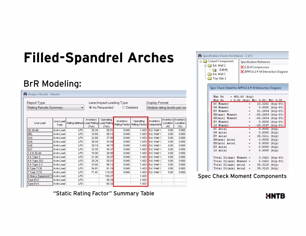
BrR Modeling:
“Static Rating Factor” Summary Table
Spec Check Moment Components
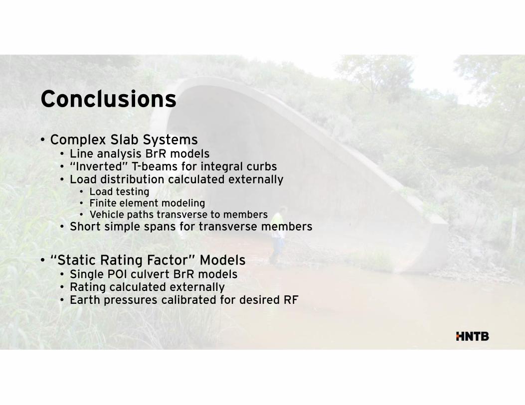
Conclusions
• Complex Slab Systems• Line analysis BrR models• “Inverted” T-beams for integral curbs• Load distribution calculated externally
• Load testing• Finite element modeling• Vehicle paths transverse to members
• Short simple spans for transverse members
• “Static Rating Factor” Models• Single POI culvert BrR models• Rating calculated externally• Earth pressures calibrated for desired RF

Questions?
Thanks to:


