ht. J. Hear Mass Transfer. Vol. 31, No. 4, pp. 731-742, 1988 Printed in Great Britain 0017-9310/88$3.00+0.00 0 1988 PergamonPress plc Local evaporative heat transfer coefficient in turbulent free-falling liquid films J. A. SHMERLERt and I. MUDAWWAR Boiling and Two-phase Flow Laboratory, School of Mechanical Engineering, Purdue University, West Lafayette, IN 47907, U.S.A. (Received 4 June 1987 and infinalform 19 August 1987) Abstract-Evaporative heating of a free-falling turbulent liquid film has been investigated experimentally and numerically. The tilm exhibited a long thermal development length persisting up to more than one half of the 781 mm long heated test section. The increased length of the development region is attributed to the formation of a boundary layer at the film interface. This boundary layer was predicted numerically and observed in temperature measurements within the film. The heat transfer coefficients are averaged over the lower section of the tube and correlated as a function of the Reynolds and Prandtl numbers. Numerical predictions are made for the development region and for fully developed heat transfer coefficients using three different eddy diffusivity models. Comparison with experimental data reveals that two of these models are fairly successful in predicting the extent of the thermal development region and the time-averaged evaporative heat transfer coefficient; yet the data indicate the need for development of a new model which accurately accounts for local and spatial wave-induced variations of film thickness. 1. INTRODUCTION THE CHARACTERISTICS of free-falling evaporating films are of importance in many aspects of thermal engin- eering and chemical processes. While a need has been shown for an improved understanding of falling film transport processes, the amount of heat transfer data remains limited as shown by the summary of exper- imental investigations in Table 1. The study by Chun and Seban [2] is the most often sighted reference on evaporative heating of falling films. They presented correlations for heat transfer coefficients in the wavy laminar and the turbulent regimes as functions of the Reynolds and Prandtl numbers. They also found a correlation for the tran- sition Reynolds number as a function of Prandtl num- ber. Fujita and Ueda [3] presented evaporation data at a pressure of 1 atm. Their data followed the trends shown by Chun and Seban but were an average of 10% higher. While the experimental work is limited, many eddy diffusivity models have been developed specifically for predicting heat transfer coefficients for falling films [4-151. The majority of these models use a modified Van Driest function near the wall and a damping function to model the turbulent activity at the film interface. Mills and Chung [8] presented a model that uses a modified Van Driest function and a heat-mass transfer analogy with the gas absorption results of Lamourelle and Sandal1 [ 161 to model the eddy diffu- sivity near the film interface. Hubbard et al. [l l] used t Current address : AT&T Bell Laboratories, Liberty Cor- ners, NJ 07060, U.S.A. a similar approach with the addition of new gas absorption data and the effects of concurrent vapor flow. Seban and Faghri [12] looked at several model- ing schemes in an attempt to predict Chun and Seban’s data and new data collected on essentially the same apparatus as Chun’s [17]. They concluded that the best predictions are made using Limberg’s [9] model near the wall, modified with the interface damp- ing function of Mills and Chung. Although their model predicts the data reasonably well, a physical inconsistency occurs as there is a discontinuity between the two functions. Mudawwar and El-Masri [ 151presented an eddy diffusivity function which com- bines the Van Driest damping function and the exper- imental turbulence data of Ueda et al. [ 181to produce an eddy diffusivity profile that is continuous over the entire film thickness. All of the turbulence models are semi-empirical, but are based on a very limited data base. The present study provides a new data base by obtaining heat transfer coefficients over a wide range of Reynolds and Prandtl numbers. A test section 78 1 mm long was used to determine heat transfer coefficients during thermal development and in the fully developed regime, and to determine the behavior of the tem- perature profile across the film thickness. A numerical study was also performed to determine how well the available turbulence models predict the new data. 2. EXPERIMENTAL SYSTEM The experimental apparatus was the same as that described in ref. [19]. The test section shown in Fig. 1 was 25.4 mm in diameter and consisted of a 300 mm long porous plastic film distributor, a 757 mm long 731
Transcript
ht. J. Hear Mass Transfer. Vol. 31, No. 4, pp. 731-742, 1988 Printed in Great Britain
0017-9310/88$3.00+0.00 0 1988 Pergamon Press plc
Local evaporative heat transfer coefficient in turbulent free-falling liquid films
J. A. SHMERLERt and I. MUDAWWAR
Boiling and Two-phase Flow Laboratory, School of Mechanical Engineering, Purdue University, West Lafayette, IN 47907, U.S.A.
(Received 4 June 1987 and infinalform 19 August 1987)
Abstract-Evaporative heating of a free-falling turbulent liquid film has been investigated experimentally and numerically. The tilm exhibited a long thermal development length persisting up to more than one half of the 781 mm long heated test section. The increased length of the development region is attributed to the formation of a boundary layer at the film interface. This boundary layer was predicted numerically and observed in temperature measurements within the film. The heat transfer coefficients are averaged over the lower section of the tube and correlated as a function of the Reynolds and Prandtl numbers. Numerical predictions are made for the development region and for fully developed heat transfer coefficients using three different eddy diffusivity models. Comparison with experimental data reveals that two of these models are fairly successful in predicting the extent of the thermal development region and the time-averaged evaporative heat transfer coefficient; yet the data indicate the need for development of a new model which
accurately accounts for local and spatial wave-induced variations of film thickness.
1. INTRODUCTION
THE CHARACTERISTICS of free-falling evaporating films are of importance in many aspects of thermal engin- eering and chemical processes. While a need has been shown for an improved understanding of falling film transport processes, the amount of heat transfer data remains limited as shown by the summary of exper- imental investigations in Table 1.
The study by Chun and Seban [2] is the most often sighted reference on evaporative heating of falling films. They presented correlations for heat transfer coefficients in the wavy laminar and the turbulent regimes as functions of the Reynolds and Prandtl numbers. They also found a correlation for the tran- sition Reynolds number as a function of Prandtl num- ber. Fujita and Ueda [3] presented evaporation data at a pressure of 1 atm. Their data followed the trends shown by Chun and Seban but were an average of 10% higher.
While the experimental work is limited, many eddy diffusivity models have been developed specifically for predicting heat transfer coefficients for falling films [4-151. The majority of these models use a modified Van Driest function near the wall and a damping function to model the turbulent activity at the film interface. Mills and Chung [8] presented a model that uses a modified Van Driest function and a heat-mass transfer analogy with the gas absorption results of Lamourelle and Sandal1 [ 161 to model the eddy diffu- sivity near the film interface. Hubbard et al. [l l] used
t Current address : AT&T Bell Laboratories, Liberty Cor- ners, NJ 07060, U.S.A.
a similar approach with the addition of new gas absorption data and the effects of concurrent vapor flow. Seban and Faghri [12] looked at several model- ing schemes in an attempt to predict Chun and Seban’s data and new data collected on essentially the same apparatus as Chun’s [17]. They concluded that the best predictions are made using Limberg’s [9] model near the wall, modified with the interface damp- ing function of Mills and Chung. Although their model predicts the data reasonably well, a physical inconsistency occurs as there is a discontinuity between the two functions. Mudawwar and El-Masri [ 151 presented an eddy diffusivity function which com- bines the Van Driest damping function and the exper- imental turbulence data of Ueda et al. [ 181 to produce an eddy diffusivity profile that is continuous over the entire film thickness.
All of the turbulence models are semi-empirical, but are based on a very limited data base. The present study provides a new data base by obtaining heat transfer coefficients over a wide range of Reynolds and Prandtl numbers. A test section 78 1 mm long was used to determine heat transfer coefficients during thermal development and in the fully developed regime, and to determine the behavior of the tem- perature profile across the film thickness. A numerical study was also performed to determine how well the available turbulence models predict the new data.
2. EXPERIMENTAL SYSTEM
The experimental apparatus was the same as that described in ref. [19]. The test section shown in Fig. 1 was 25.4 mm in diameter and consisted of a 300 mm long porous plastic film distributor, a 757 mm long
731
732 J. A. SHMERLER and I. MUDAWWAR
k Ka L Pr Pr, 4 4w Re T
r,, T, TS T sat
TW T+
u
NOMENCLATURE
acceleration due to gravity heat transfer coefficient for evaporative
heating, q,l(T,- T,,,) dimensionless heat transfer coefficient,
(M 2’3)/(kg”3)
thermal conductivity Kapitza number, (p’g)/(pa’) length of the heated section Prandtl number turbulent Prandtl number, E,,,/E,, local heat flux wall heat flux Reynolds number, 4l?/p local temperature inlet temperature mean temperature interface temperature saturation temperature wall temperature dimensionless temperature,
~y*(Tw- Wqw
local velocity component in the flow direction
u* friction velocity, J(r,/p) u + dimensionless film velocity, u/u* X longitudinal position from the entrance to
the heated section
Y distance from the solid wall
Y+ dimensionless distance from the solid wall, yu*/v.
Greek symbols
F thermal diffusivity mass flow rate per unit film width
6 film thickness 6 + dimensionless film thickness, Gu*/v
Eh eddy heat diffusivity
s, eddy momentum diffusivity
p dynamic viscosity V kinematic viscosity
P liquid density d surface tension Z local shear stress
7, wall shear stress.
Table 1. Experimental studies on evaporative heating of falling films
1
Author
Struve [l] Chun and Seban [2] Fujita and Ueda [3]
Injection method Tube diameter
Adiabatic length Heated length Heating method Test fluid Reynolds number Prandtl number
nozzle 32 mm o.d. 26 mm i.d.
0 1250 mm
steam condensation Rll
x7cL8800 4.12
sintered tube 28.6 mm o.d. 28.4 mm id.
317.5 mm 292 mm
electrical resistance water
320-21000 1.77-5.7
sintered tube (152 mm) porous plastic (300 mm) 16 mm o.d. 25.4 mm o.d. 14 mm i.d. 24.6 mm id.
250 mm copper rod 757 mm 6OOand 1OOOmm 781 mm
electrical resistance electrical resistance water water
700-9100 500&37 500 1.8-2.0 1.75-5.4
adiabatic hydrodynamic development section made volumetric heat generation within the stainless steel of G-10 fiberglass based phenolic plastic, and heated tube. Reference [19] describes the apparatus and ther- length of 781 mm. The latter was a polished stainless mocouple locations in detail. The saturation temp- steel tube with a wall thickness of 0.41 mm through erature was both measured and calculated from the which a high d.c. current was passed to produce a chamber pressure, determined from measurements constant wall flux. made with a high accuracy pressure transducer.
Heat transfer coefficients were determined from the difference between the wall temperature and the satu- ration temperature. Pairs of thermocouples 180” apart at 17 locations along the heated length measured the inside wall temperature. The pairs were unequally spaced with the thermocouples grouped closer to- gether at the top of the heated length to monitor ther- mal boundary layer development. The outside wall temperature was calculated from these measure- ments by performing a control volume energy balance assuming an adiabatic inner surface and uniform
All tests were performed using deionized water which was deaerated before introduction into the experimental apparatus. A vacuum pump removed noncondensible gases from the system to give pure saturated conditions within the flow loop. After charging the system and achieving equilibrium pres- sure and temperature conditions, fluid was circulated at the maximum flow rate to give the greatest film thickness. The selected operating conditions were achieved through the control of the chamber pressure and inlet temperature of the fluid. The temperature
Present study
Local evaporative heat transfer coefficient in turbulent free-falling liquid films 733
r--
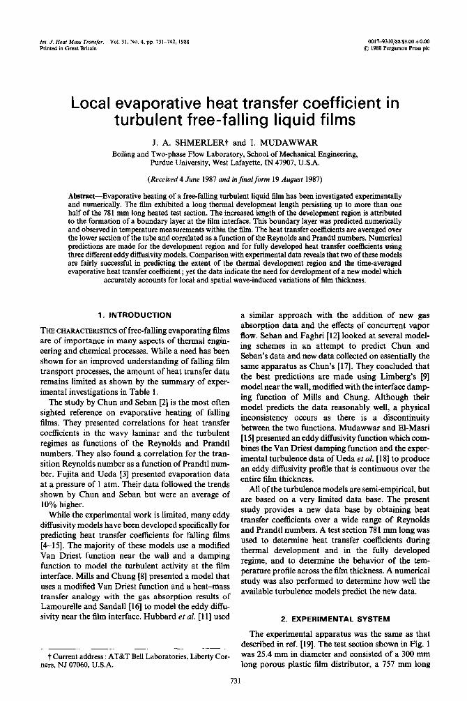
FIG. 1. Schematic diagram of the fluid delivery system.
was controlled through a heat exchanger located upstream of the test chamber. The pressure was main- tained at a level equal to the saturation value by con- trolling the condensation rate of the generated vapor, which was achieved by adjusting the amount of cool- ant passing through the condensing heat exchanger. At high power levels, where a large amount of vapor was generated, a vacuum pump supplemented the condenser.
During the tests, the power level was kept below the wall heat flux necessary for the onset of nucleate boiling (ONB). This value was determined from a manipulation of a correlation for ONB presented in ref. 1201 using the correlation for the evaporation heat transfer coefficient presented by Chun and Seban [2]. The wall heat flux was always kept at least 25% below the value determined to produce boiling incipience.
Temperature measurements along the heated length were recorded upon reaching steady-state conditions. New test conditions were achieved by decreasing the flow rate to give a new Reynolds number, adjusting the condensate rate to maintain the desired saturation level, and adjusting the power to the proper level. This procedure was continued until any further decrease in flow rate caused film dryout. The flow rate was then increased to the maximum value and the chamber pressure was modified to give different saturated con- ditions.
3. EXPERIMENTAL RESULTS
Heat transfer results for films undergoing evap- orative heating have been obtained over a Reynolds number range of 4990 to 37 620 for Prandtl numbers
AL q 37620
0.5 t
Pr = 1.75 0 31220 A 23060
0.4 0 17460
l
‘k 0.3
0 0.2 0.4 0.6 0.0 1.0
x/L
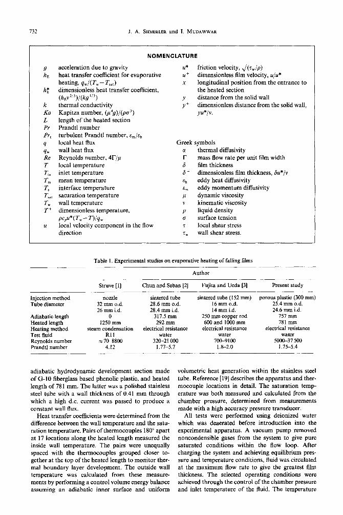
FIG. 2. Variation of the evaporative heat transfer coefficient with distance along the heated section for Pr = 1.75.
between 1.75 and 5.42. Figures 2-5 show typical results for the heat transfer coefficient as a function of position along the heated length. A complete docu- mentation of the local heat transfer data and oper- ating conditions of this study can be found in ref. [21]. The position is normalized with respect to the total heated length, L, and the fluid properties are based on the saturation temperature. The thermal development region persisted over more than one half of the heated length, longer than that observed during tests involv- ing sensible heating of falling films [ 191. This increased development length is attributed to boundary layer development at the film interface.
Figure 6 is a qualitative comparison of two films : one undergoing sensible heating, and the other, evap-
734 J. A. SHMERLER and 1. MUDAWWAR
01 ’ ’ ’ ’ ’ ’ ’ ’ ’ 0 0.2 0.4 0.6 0.8 I.0
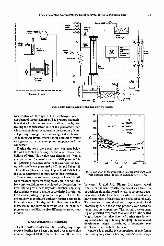
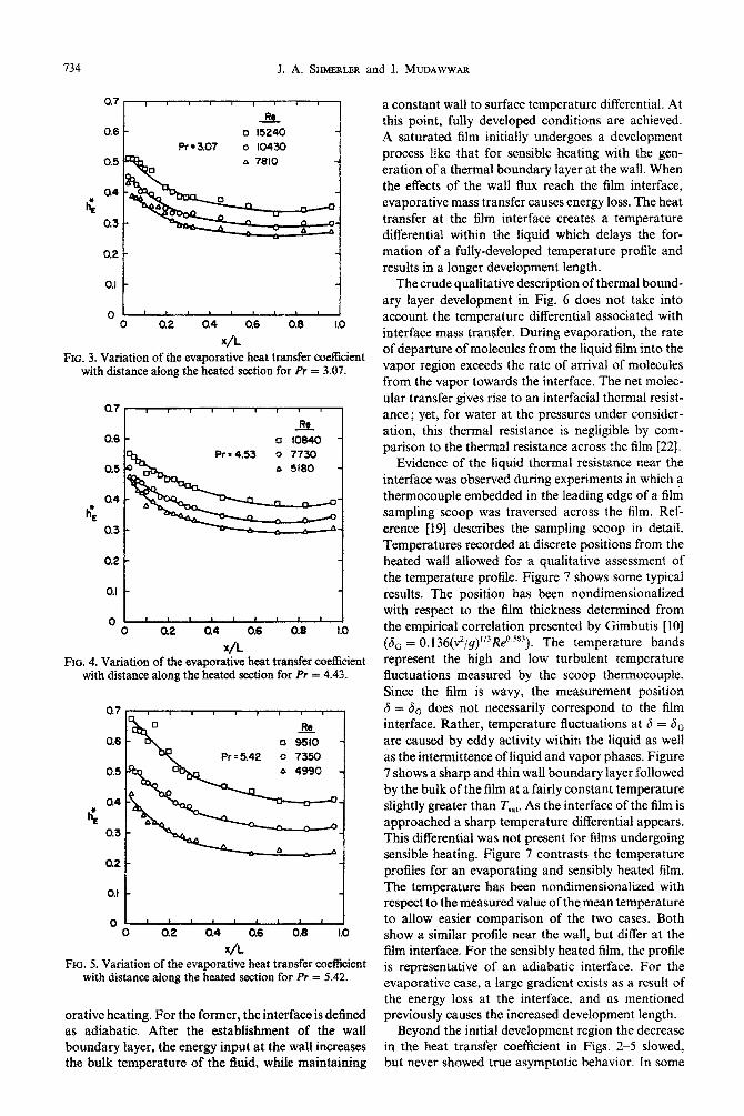
RIG. 3. Variation of the evaporative heat transfer coefficient with distance along the heated section for Pr = 3.07.
0.6
0’ ’ ’ ’ ’ I ’ ’ ’ ’ 0 0.2 84 0.6 0.8 I.0
x/k FIG. 4. Variation of the evaporative heat transfer coefficient
with distance along the heated section for Pr = 4.43.
.& a 9510 -
8 4990 -
01 ’ ’ ’ ’ ’ ’ ’ ’ ’ 1 0 0.2 Q4 0.6 0.8 1.0
x/L FOG. 5. Variation of the eva~rative heat transfer coefficient
with distance along the heated section for Pr = 5.42.
orative heating. For the former, the interface is defined as adiabatic. After the establishment of the wall boundary layer, the energy input at the wall increases the bulk temperature of the iluid, while m~n~ining
a constant wall to surface temperature differential. At this point, fully developed conditions are achieved. A saturated film initially undergoes a development process like that for sensible heating with the gen- eration of a thermal boundary layer at the wall. When the effects of the wall flux reach the film interface, evaporative mass transfer causes energy loss. The heat transfer at the film interface creates a temperature differential within the liquid which delays the for- mation of a fully-deve~o~d temperature profile and results in a longer development length.
The crude qualitative description of thermal bound- ary layer development in Fig. 6 does not take into account the temperature differential associated with interface mass transfer. During evaporation, the rate of departure of molecules from the Iiquid film into the vapor region exceeds the rate of arrival of molecules from the vapor towards the interface. The net moiec- ular transfer gives rise to an interfacial thermal resist- ance; yet, for water at the pressures under consider- ation, this thermal resistance is negligible by com- parison to the thermal resistance across the film [22].
Evidence of the liquid thermal resistance near the interface was observed during experiments in which a thermocouple embedded in the leading edge of a film sampling scoop was traversed across the film. Ref- erence [19] describes the sampling scoop in detail. Temperatures recorded at discrete positions from the heated wall allowed for a qualitative assessment of the temperature profile. Figure 7 shows some typical results. The position has been nondimensionalized with respect to the film thickness determined from the empirical correlation presented by Gimbutis [lo] (6, = 0.1 36(v2/g)“3Reo.s~3). The temperature bands represent the high and low turbulent tem~rature fluctuations measured by the scoop thermocouple. Since the film is wavy, the measurement position 6 = 8c does not necessarily correspond to the film interface. Rather, temperature fluctuations at 6 = 6o are caused by eddy activity within the liquid as well as the inte~ittence of liquid and vapor phases. Figure 7 shows a sharp and thin wall boundary layer followed by the bulk of the film at a fairly constant temperature slightly greater than T,,,. As the interface of the film is approached a sharp temperature differential appears. This differential was not present for films undergoing sensible heating. Figure 7 contrasts the temperature profiles for an evaporating and sensibly heated film. The temperature has been nondimensionalized with respect to the measured value of the mean temperature to allow easier comparison of the two cases. Both show a similar profile near the wall, but differ at the film interface. For the sensibly heated film, the profile is representative of an adiabatic interface. For the evaporative case, a large gradient exists as a result of the energy loss at the interface, and as mentioned previously causes the increased development length.
Beyond the initial development region the decrease in the heat transfer coefficient in Figs. 2-5 slowed, but never showed true asymptotic behavior. In some
Local evaporative heat transfer coefficient in turbulent free-falhng liquid films 73s
FUllJ DrJv@twd Thermal Etowubry Loyrr
Sensible Heoting
Wry Law
VL w I
Oawmnt at th Wall
Film Interface
Evaporative I Heating
FIG. 6. Development of the thermal boundary Iayer for hydr~yn~i~ily fully developed film flow over a uniformly heated wall for the cases of sensible and evaporative heating.
2.0 I -
- _ Semibla mlnp E
Re=Kmo _ R= 5.08
1.5 - - Evooorotim R=5.17 I
*tO=-
-
J. l.O- a,
H8l-M
l-4 Y
M Y 0.5 -
w-
-
0 - I
as0 0.75 LOO 1.25
T,-T L-L
FIG. 7. Comparison of temperature profiles across the film for the cases of sensible and evaporative heating.
cases, the heat transfer coefficient showed a slight enhan~e~t over the last two meas~ement positions (650 and 750 mm from the start of the heated length). This enhancement was a result of increased turbulent activity caused by longitudinal changes in interfacial waves.
To better understand the effects of interfacial waves on turbulent velocity fluctuations, videographic analysis of film motion was employed for rep- resentative operating conditions. Individual frame analysis revealed the existence of interfacial waves covering a wide spectrum of wavelengths. An inde- pendent study was also conducted to measure film thickness fluctuations on a vertical adiabatic column using water as the working fluid. A high resolution
conductance probe recently developed by Koskie et
al. [23] at Purdue’s Boiling and Two-phase Flow Lab- oratory was employed in this study. A time record of interfacial waves was obtained at a position 1895 mm below the lower end of the porous injection section. Typical variation of local film thickness is shown in Fig. 8. Waves formed at the film interface appear to be a combination of large waves with small ripples superimposed on the large waves. Strong spectral components for large and small waves were typically in the range of 10-20 and 75-150 Hz, respectively. Film waviness is complicated further by variations in both the instantaneous and the time-averaged values of film thickness with film travel. According to a study by Takahama and Kato [24], the minimum film thick- ness decreases in the direction of fluid Row, while the maximum thickness increases fairly linearly with distance as more filmmass is accumulated into larger and faster waves. The severe fluctuations of instan- taneous film thickness from their time-averaged values and the longitudinal changes in wave characteristics are strong evidence against common belief that an idealized smooth interface is a reasonable represen- tation of film flow.
The work by Brumfield and Theofanous [25] rep- resents the only systematic attempt known to the authors of predicting the evaporative heat transfer coefficient across turbulent wavy films. They used film hydrodyn~cs data determined by Telles f24l and Chu and Dukler [27] to develop a coherent transport model which accounts for film thickness fluctuations. The model was used to predict heat transfer data for free-falling and shear-driven films using wave par- ameters correlated experimentally at Pr - 5.7. Since there is no firm basis for predicting wave parameters
736 J. A. SHMERLER and I. MUDAWWAR
g 6.0
g 4.0 s .z b 2.0
E 0.0 0.0 0.1 0.2 0.3
Mean Thickness
0.4 0.5 0.6 0.7 0.8
Time (SEC)
FIG. 8. Film thickness variation with time for an adiabatic water film at 26°C.
for different fluids or for temperatures corresponding to different Prandtl numbers, the usefulness of the Brumfield and Theofanous model is limited by the availability of film hydrodynamics data for the cor- responding fluid and operating conditions. Fur- thermore, hydrodynamic correlations obtained from adiabatic film experiments may not apply for films subjected to evaporative heating due to the sensitivity of surface tension to temperature gradients along the film interface.
The developmental nature of the film precludes the determination of a universal correlation for a fully developed heat transfer coefficient. A correlation was determined for hi averaged over the positions cor- responding to x/L = 0.576, 0.704 and 0.832 from the inlet to the heated length. These positions were chosen because the heat transfer coefficient appeared to exhi- bit a minimum value for all the tests in this area. As shown in Fig. 9 the average heat transfer coefficient was correlated as a function of the Reynolds and Prandtl numbers as follows :
h* = 0 0038Re0,35 Pro.“. E ’ (1)
The correlation has an average error of 6%, a maximum error of 14.9% and a standard deviation of 0.023 and all fluid properties are based on the saturation temperature.
The Prandtl number exponent in equation (1) exceeds that of Chun and Seban’s correlation (hi = 0.0038Re”.4 Pr”.65). Since this exponent is much greater than that associated with single-phase forced convection (Nu cc Pro,“), heat transfer near the film interface must occur by a different transport mech- anism. Due to limitations of the present data base, the dependence of the heat transfer coefficient on par-
ameters other than the Reynolds and Prandtl numbers, such as the Kapitza number, Ku, could not be assessed. It is well known that surface tension for- ces both influence the interfacial wave characteristics and dampen turbulent velocity fluctuations near the film interface. Interfacial instabilities may also be amplified by surface tension gradients associated with temperature variations along the film interface. Since the Kapitza number is proportional to p4, the high Prandtl number exponent in equation (1) may indirectly account for these effects.
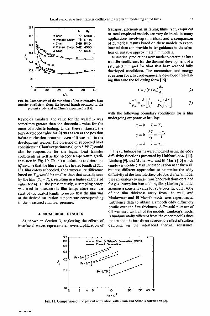
Figure 10 shows a comparison between the present data and the data presented by Chun for the heat transfer coefficient as a function of position along the heated length. Chun’s data are nondimensionalized with respect to the length of the heated section used in the present study. For higher Prandtl numbers, the slopes are similar near the top of the heated length, but Chun’s data begins to level off earlier. The short length of Chun’s test section, 292 mm, prevented the determination of downstream effects. At lower Prandtl numbers, there is a much steeper gradient at the start of the heated length, after which similar slopes can be observed. Chun’s data do not appear to reach a fully developed state since the test section length prevented any further measurements.
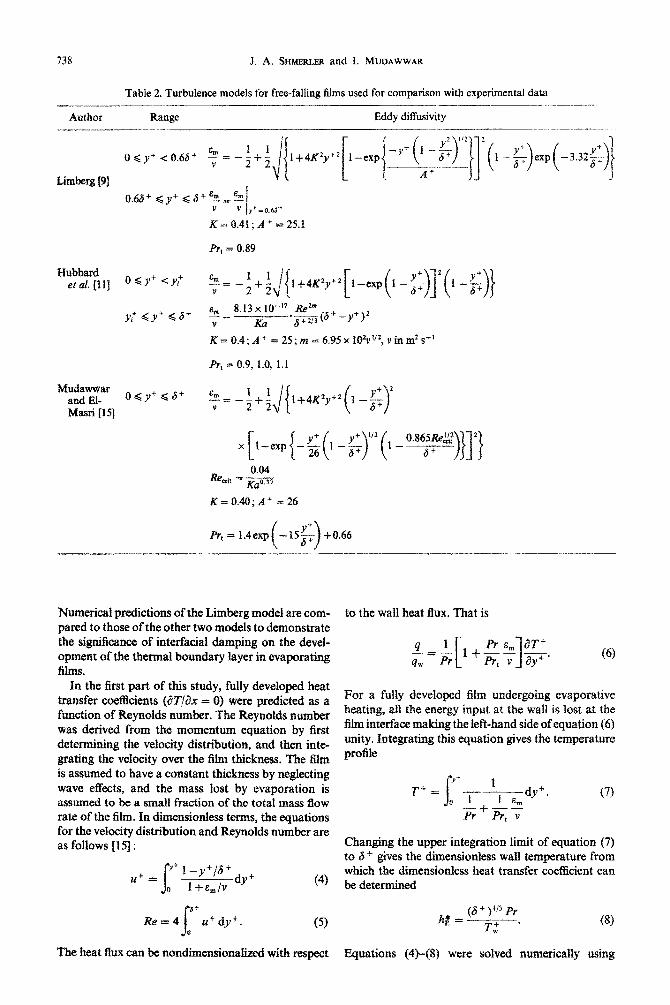
Figure 11 is a comparison of Chun and Seban’s heat transfer correlation with the present correlation. The agreement at higher Prandtl numbers is good, but there is a large difference at the lower Prandtl number of 1.75. This difference could be a result of the occur- rence of nucleate boiling or subcooled inlet conditions in Chun’s experiments, or due to data in the thermal development region used in his correlation. In Chun’s experiments, at a pressure of 1 atm, and at lower
FIG. 9. Correlation of the evaporative heat transfer coefficient for Re = 499&37 620 and Pr = 1.75-5.42.
Local evaporative heat transfer coefficient in turbulent free-falling liquid films 137
0.6
0.2
0’ ’ ’ ’ ’ ’ ’ ’ ’ ’ J 0 0.2 0.4 0.6 0.6 1.0
x/L
FIG. 10. Comparison of the variation of the evaporative heat transfer coefficient along the heated length obtained in the
present study and in Chun’s experiments [17].
Reynolds numbers, the value for the wall flux was sometimes greater than the theoretical value for the onset of nucleate boiling. Under these instances, the fully developed value for & was taken at the position before nucleation occurred, even if it was still in the development region. The presence of subcooled inlet conditions in Chun’s experiments (up to 3.39”C) could also be responsible for the higher heat transfer coefficients as well as the steeper temperature gradi- ents seen in Fig. 10. Chun’s calculations to determine h$ assume that the film enters the heated length at T,,,. If a film enters subcooled, the temperature difference based on T,,, would be smaller than that actually seen by the film (T,,,- Ti,), resulting in a higher calculated value for hg. In the present study, a sampling scoop was used to measure the film temperature near the start of the heated length to insure that the film was at the desired saturation temperature corresponding to the measured chamber pressure.
4. NUMERICAL RESULTS
As shown in Section 3, neglecting the effects of interfacial waves represents an oversimplification of
transport phenomena in falling films. Yet, empirical or semi-empirical models are very desirable in many applications involving thin films, and a comparison of numerical results based on these models to exper- imental data can provide better guidance in the selec- tion of suitable approximate film models.
Numerical predictions were made to determine heat transfer coefficients for the thermal development of a saturated film and for films that have reached fully developed conditions. The momentum and energy equations for a hydrodynamically developed free-fall- ing film take the following form [15] :
with the following boundary conditions for a film undergoing evaporative heating :
x=0 T = Tsat
y=o aT=-_q, 3~ k
y=6 T = T,,,.
The turbulence terms were modeled using the eddy diffusivity functions presented by Hubbard et al. [ 111, Limberg [9], and Mudawwar and El-Masri [ 151 which employ a modified Van Driest equation near the wall, but use different approaches to determine the eddy diffusivity at the film interface. Hubbard et al.% model uses an analogy to mass transfer correlations obtained for gas absorption into a falling film ; Limberg’s model assumes a constant value for em/v over the outer 40% of the film thickness away from the wall, and Mudawwar and El-Masri’s model uses experimental turbulence data to obtain a smooth eddy diffusivity profile over the film thickness. A Prandtl number of 0.9 was used with all of the models. Limberg’s model is fundamentally different from the other models since it does not take into direct account the effect of surface damping on the interfacial thermal resistance.
0.7 I
0.6 - --- Chun a Sabon’s cofrelotion (1971) - 0.5 Present Cormlation -
0.4 -
a3 .
h’E
0.1 I - 2 3 4 5 IO 20 30 4050
Re x 16’
FIG. 11. Comparison of the present correlation with Chun and Seban’s correlation [2].
738 J. A. SHMERLER and I. MUDAWWAR
Table 2. Turbulence models for free-falling films used for comparison with experimental data
Author Range Eddy diffusivity
K = 0.4; A * = 25; as = 6.95 x IO?V’~~, v in m’ s-’
Mudawwar and EI- ogy+ <.6+
Masri [IS]
0.04 &tit = p
K=O&;A+=26
prt = IAexp
Numerical predictions of the Limberg model are com- pared to those of the other two models to demonstrate the significance of interfacid damping on the devel- opment of the thermal boundary layer in evaporating films.
In the first part of this study, fully developed heat transfer coefficients (ZW,‘&z = 0) were predicted as a function of Reynolds number. The Reynoids rmmber was derived from the moments equation by first dete~ning the velocity dis~bu~on, and then inte- grating the velocity over the fdm thickness. The tilm is assumed to have a constant thickness by neglecting wave effects, and the mass lost by evaporation is assumed to be a small fraction of the total mass flow rate of the film. In dimensionless terms, the equations for the velocity distribution and Reynolds number are as follows [IS] : yf u+ = s 1 -y+p+
1 +e,/v W’ 0
Q’
Rt?=4 s .+dyi. 0
(5)
The heat flux can be nondimensionalized with respect Equations (4)-(g) were solved numericalfy using
to the wall heat flux. That is
f=pl,[1+~~]~. (6)
For a fully developed film undergoing evaporative heating, ah the energy input at the wall is lost at the film interface making the left-hand side of equation (6) unity. integrating this equation gives the temperat~e profile
T” = (7)
Changing the upper integration limit of equation (7) to 6 + gives the dimen~onIess wall temperature from which the dimensionless heat transfer coef&ient can be determined
Local evaporative heat transfer coefficient in turbulent free-falling liquid films
1.5 1 I I , 1 0 1 I 7 Rs=Klooo --- Mu&mar a El-Maui (1966)
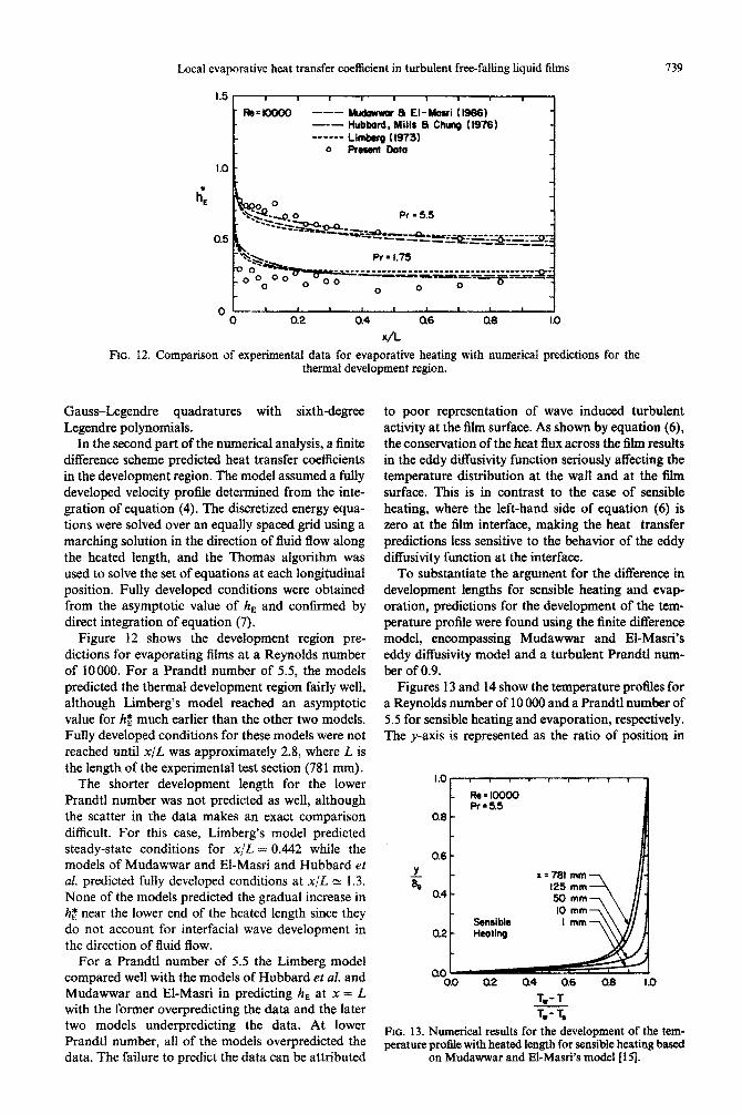
FIG. 12. Comparison of ex~~rnen~l data for evaporative heating with numerical predictions for the thermal development region.
Gauss-Legendre quadratures with sixth-degree Legendre polynomials.
In the second part of the numerical analysis, a finite difference scheme predicted heat transfer coefficients in the development region. The model assumed a fully developed velocity profile determined from the inte- gration of equation (4). The discretized energy equa- tions were solved over an equally spaced grid using a marching solution in the direction of fled flow along the heated length, and the Thomas algorithm was used to solve the set of equations at each longitudinal position. Fully developed conditions were obtained from the asymptotic value of hE and confirmed by direct integration of equation (7).
Figure 12 shows the development region pre- dictions for evaporating films at a Reynolds number of 10000. For a Prandtl number of 5.5, the models predicted the thermal development region fairly well, although Limberg’s model reached an asymptotic value for hb much earlier than the other two models. Fully developed conditions for these models were not reached until x/L was appro~mately 2.8, where L is the length of the experimental test section (781 mm).
The shorter development length for the lower Prandtl number was not predicted as well, although the scatter in the data makes an exact comparison difficult. For this case, Limberg’s model predicted steady-state conditions for x/L = 0.442 while the models of Mudawwar and El-Ma& and Hubbard et al. predicted fully developed conditions at x,fL N 1.3. None of the models predicted the gradual increase in hz near the lower end of the heated length since they do not account for interfacial wave development in the direction of fluid flow.
For a Prandtl number of 5.5 the Limberg model compared well with the models of Hubbard et al. and Mudawwar and El-Masri in predicting h, at x = L with the former overpredicting the data and the later two models underpredicting the data. At lower Prandtl number, all of the models overpredicted the data. The failure to predict the data can be attributed
739
to poor representation of wave induced turbulent activity at the film surface. As shown by equation (6), the conservation of the heat IIux across the film results in the eddy diffusivity function seriously affecting the temperature distribution at the wall and at the film surface. This is in contrast to the case of sensible heating, where the left-hand side of equation (6) is zero at the film interface, making the heat transfer predictions less sensitive to the behavior of the eddy ~ffusivity function at the interface.
To substantiate the argument for the difference in development lengths for sensible heating and evap- oration, predictions for the development of the tem- perature profile were found using the finite difference model, encompassing Mudawwar and El-Ma&s eddy diffusivity model and a turbulent Prandtl num- ber of 0.9.
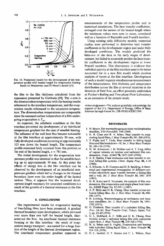
Figures 13 and 14 show the temperature profiles for a Reynolds number of 10 000 and a Prandtl number of 5.5 for sensible heating and evaporation, respectively. The y-axis is represented as the ratio of position in
0.0 02 Q4 0.6 0.6 I.0
T,-T
TV- Ts
FIG. 13. Numerical results for the development of the tem- perature profile with heated length for sensible heating based
on Mudawwar and El-Ma&% model [IS$
740 J. A. SHMERLER and 1. MUDAWWAR
1.0 I I I I I 1 1
Re=loooO Pr = 5.5 A
II H Q6
0.4
0.2
0.0 0.0 a2 0.4 0.6 0.8 1.0
E-B FIG. 14. Numerical results for the development of the tem- perature profile with heated length for evaporative heating
based on Mudawwar and El-Masri’s model [ 151.
the film to the film thickness calculated from the expression presented by Gimbutis [lo]. The x-axis is the dimensionless temperature with the heating results referenced to the interface temperature, and the evap- oration results referenced to the saturation tempera- ture. The dimensionless temperatures are comparable since the assumed surface temperature of a film under- going evaporation is T,,,.
As expected, the adiabatic condition at the film interface prevented the development of an interfacial temperature gradient for the case of sensible heating. The influence of the wall heat flux became noticeable at the film interface at approximately 50 mm, with fully developed conditions occurring at approximately 125 mm down the heated length. The temperature profile remained fairly constant from this position to the end of the heated length, x = 781 mm.
The initial development for the evaporation tem- perature profile was identical to that for sensible heat- ing up to approximately 50 mm. At this point the effects of energy loss at the film interface can be observed by the development of an interfacial tem- perature gradient which led to changes in the thermal boundary layer over the entire length of the heated section. Thus, it appears that the increased devel- opment length necessary for saturated conditions is a result of the growth of a thermal resistance at the film interface.
5. CONCLUSlONS
The experimental results for evaporative heating of free-falling films have been presented. A gradual thermal boundary layer development, which persisted over more than one half the heated length, char- acterized the flow. An interfacial thermal resistance forming at the film interface-the result of evap- orative energy transport-accounted for a large frac- tion of the length of the thermal development region.
measurements of the temperature profile and in numerical simulations. The heat transfer coefficients, averaged over the section of the heated length where the minimum values were seen to occur, correlated well as a function of Reynolds and Prandtl numbers.
Using existing eddy diffusivity models, numerical studies were performed to determine heat transfer coefficients in the development region and under fully developed conditions. The models predicted the behavior of the data in the early stages of devel- opment, but failed to accurately predict the heat trans- fer coefficients in the development region at lower Prandtl numbers. This discrepancy is evidence that
turbulent activity at the film interface need to be better accounted for in a new film model which involves analysis of waves at the film interface. Development of such a model requires simultaneous measurements of the instantaneous film thickness and temperature distribution across the film at several locations in the direction of fluid flow, an effort presently undertaken at Purdue’s Boiling and Two-phase Flow Laboratory as an extension of the present study.
Acknowledgement-The authors gratefully acknowledge the support of the U.S. Department of Energy, Office of Basic Sciences through Grant No. DE-FG02-85ER13398.
REFERENCES
I. H. Struve, Der warmeubergang an einen verdampfenden rieseltilm, VDf ~orschH~. 534 (1969).
2. K. R. Chun and R. A. Sebau. Heat transfer to evan-
3
4,
5
6
7
8
9.
IO.
11.
12.
The interfacial temperature gradient appeared in 13. 0. C. Sandall, 0. T. Hanna and C. L. Wilson, Heat
orating liquid films, J. Heat Tr&s&r93,391-396 (197i). T. Fujita and T. Ueda, Heat transfer to falling liquid films and film breakdown-II, ht. J. Heat Mass Transfer 21, 109-118 (1978). W. M. Rohsenow, J. H. Webber and A. T. Ling, Effect of vapour velocity on laminar and turbulent film con- densation, Trans. ASME 78.1637-1643 0956). A. E. Dukler, Fluid mechanics and heat transfer in ver- tical falling-film systems, Chem. Engng Prog. 56, l-10 (1960). A. Iribarne, A. D. Gosman and D. B. Spalding, A theor- etical and experimental investigation of diffusion-con- trailed electrolytic mass transfer between a falling film and a wall. Inc. J. Heat Mass Transfer 10, 1661-1676 (1967). H. R. Kunz and S. Yerazunis, An analysis of film con- densation, tilm evaporation and single-phase heat trans- fer, ASME Paper No. 67-HT-1 (1967). A. F. Mills and D. K. Chung, Heat transfer across tur- bulent falling films, fnr. J. Heat Mass Transfer 16, 694- 696 (1973). H. Limberg, Warmeubergang an turbulente und lami- nare rieseltilme, fnr. J. Hear Mass Tramfer 16, 1691- 1702 (1973). G. Gimbutis, Heat transfer of a turbulent falling film, Proc. 5th Int. Heat Transfer Conf, Tokyo, Japan, Vol. 2, pp. 85-89 (1974). G. L. Hubbard, A. F. Mills and D. K. Chung, Heat transfer across a turbulent falling film with concurrent vapor gow, J. Heat Transfer 9& 3iS320 (1976). R. A. Seban and A. Faghri, Evaporation and heating with turbulent falling liquid films, J. Heat Transfer 98, 315-318 (1976).
Local evaporative heat transfer coefficient in turbulent free-falling liquid films 741
14.
15.
16.
17.
18.
19.
20.
transfer across turbulent falling liquid films, AZChE 21. Symposium Series, Heat Transfer, Niagara Falls, pp. 3- 8 (1984). V. P. Carey, A note on heat transfer to turbulent liquid 22. falling films at high Prandtl number, A.Z.Ch.E. JI 31, 1575-1577 (1985). 23. I. Mudawwar and M. A. El-Masri, Momentum and heat transfer across f~ly-filing turbulent liquid films, Znt. J. M&phase Flow l&771-790 (1986). A. P. Lamourelle and 0. C. Sandall, Gas absorption into a turbulent liquid, Chem. Engng Sci. 27, 1035-1043 24. (1972). K. R. Chun, Evaporation from thin liquid films, Ph.D. Thesis, University of California, Berkeley (1969). H. Ueda, R. Moller, S. Komori and T. Mizushima, Eddy 25. diffusivity near the free surface of open channel flow, Znt. J. Heat Mass Transfer 20, 1127-l 136 (1977). J. A. Shmerler and I. A. Muda~ar, Local heat transfer 26. coefficient in wavy free-falling turbulent liouid films undergoing uniform sensible heating, ht. J. Heat Mass Transfer 31,67-77 (1988). J. G. Collier, Convective Boiling and Condensation, 2nd Edn, p. 152. McGraw-Hill, U.K. (1981).
21.
J. A. Sbmerler, A study of sensible heating and evap- oration in free-failing liquid films, MSME thesis, Purdue University, West Lafayette, Indiana (1986). J. G. Collier, Convective Boiling and Condensation, 2nd Fdn, pp. 316323. McGraw-Hill, U.K. (1981). J. E. Koskie, I. Mudawwar and W. G. Tiederman, Characteristics of interfacial waves on free-falling liquid films, 4th Miami Int. Symposium on Multi-pha~ Trans- port and Particulate Phenomena, Miami, Florida, 1s 17 December (1986). H. Takahama and S. Kato, Longitudinal flow charac- teristics of vertically falling liquid flms without con- current gas flow, Znt. J. ~alti~h~e Flow 6, 203-215 (1980). L. K. Brutield and T. G. Theofanous, On the pre- diction of heat transfer across turbulent liquid films, J. Hear Transfer 98,496-502 (1976). A. S. Telles, Liquid film characteristics in vertical two- phase flow, Ph.D. thesis, University of Houston, Texas (1986). K. J. Chu and A. E. Dukler, Statistical characteristics of thin, wavy films: Part II. Studies of the substrate and its wave structure, A.Z.Ch.E. JI 20,695-706 (1974).
COEFFICIENT LOCAL DE TRANSFERT DE CHALEUR EVAPORATOIRE DANSDES FILMS LIQUIDES TOMBA~S TURBULENTS
R&urn&On Btudie expCrimentalement et numkriquement le chauffage Bvaporatif d’un film liquide tur- bulent en chute libre. Le film montre une grande longueur d’ttablissement thermique qui va jusqu’8 plus de la moitit des 781 mm de longueur chauffke. La longueur accrue de la r&ion d’etablissement est attribu&e & la fo~ation d’une couche limite $ l’interface du film. Cette couche limite est pr&dite num~~quement et observee par des mesures de temp&ature dans ie film. Les coefficients de transfert thermique sont moyen& sur la section infkrieure du tube et exprimts en fonction des nombres de Reynolds et de Prandtl. Des calculs numkriques sont faits pour la r&ion d’btablissement et pour la rbgion pleinement btablie en utilisant trois modtles diffkrents de viscositi turbulente. Une comparaison avec les don&es exp&imentales r&v&e que deux de ces mod&es sont t&s ~tisfaisants dans la p&vision de l’btendue de la r&ion ~~~blis~rnent et du coefficient de transfert thermique kvaporatif moyen dans le temps; nianmoins les don&es montrent le besoin d’un nouveau modele qui prendrait en compte avec prbcision les variations locales et spaciales de
1’Cpaisseur du film induites par les ondulations.
LOKALER WARMEtiBERGANGSKOEFFIZIENT BEI DER VERDAMPFUNG AN TURBULENTEN. FREI FALLENDEN FLOSSIGKEITSFILMEN
Zusammenfassung-Die Verdampfung an einem frei fallenden turbulenten Fl~ssi~eitsfilm ist experimentell und numerisch untersucht worden. Der Film wies eine groBe thermische EinlauflBnge auf; sie erstreckte sich iiber mehr als die HIlfte der 781 mm langen Heizstrecke. Die erhijhte Einlaufllnge wird auf die Ausbildung einer Grenzschicht an der Filmoberfllche zuriickgefiihrt. Diese Grenzschicht wurde numerisch vorhergesagt und bei Tem~ratu~essungen im Film beobachtet. Die W~~e~~rgan~skoe~ienten wurden im unteren Teil des Rohres gemittelt und als Funktion von Reynolds- und Prandtl-Zahl korrefiert. Numerische Berechnungen der WBrmeiibergangskoeffizienten wurden fiir die Einlaufstrecke und fiir den Bereich der voll ausgebildeten StrGmung unter Verwendung dreier verschiedener Modelle fiir den tur- bulenten Transport durchgefiihrt. Der Vergleich mit den experimentellen Da&n enthiillt, da13 zwei dieser Modelle zum Berechnen der Ausdehnung des them&hen Einlaufs und des zeitlich gemitteften Wgr- me~bergangsk~ffi~enten bei der Verdampfung bedingt geeignet sind. Die Daten weisen auf die Notwen- digkeit hin, ein neues Model1 zu entwickeln, das lokale und rgumliche welleninduzierte Variationen der