LOCATION OF PLANAR TARGETS IN THREE SPACE FROM MONOCULAR IMAGES Karin Cornils and Plesent W. Goode NASA Langley Research Center Presented at the 1987 Goddard Conference on Space Applications of Artificial Intelligence (AI) and Robotics 1 Greenbel t, Mary1and May 13-14, 1987 (WASA-iM-10186d) L'ICATTON qF PLANAS TAPGFTS IN ThPtC ';PACT FRqM IYONRCIILAR IYAGtS (NASA. Lannley Hsseilrch Center) 13 p CSLL 039 N89-29991 uncl as G3/63 0233126 https://ntrs.nasa.gov/search.jsp?R=19890020620 2018-07-25T14:51:45+00:00Z
Transcript
LOCATION OF PLANAR TARGETS I N THREE SPACE FROM MONOCULAR IMAGES
K a r i n C o r n i l s and P lesent W. Goode NASA Langley Research Center
Presented a t t he 1987 Goddard Conference on Space App l i ca t i ons o f A r t i f i c i a l I n t e l l i g e n c e ( A I ) and Robo t i cs
1
Greenbel t, Mary1 and May 13-14, 1987
( W A S A - i M - 1 0 1 8 6 d ) L ' ICATTON q F PLANAS T A P G F T S I N T h P t C ';PACT FRqM IYONRCIILAR I Y A G t S ( N A S A . L a n n l e y Hsseilrch Center) 13 p CSLL 039
LOCATION OF PLANAR TARGETS I N THREE SPACE FROM MONOCULAR IMAGES
BY
K a r i n Corni 1 s Plesent W. Goode
NASA Langley Research Center
ABSTRACT
Many pieces o f e x i s t i n g and proposed space hardware t h a t would be t a r g e t s
Examples i n c l u d e the b ios tack modules on t h e Long Dura t ion Exposure o f i n t e r e s t f o r a t e l e r o b o t can be represented as p lanar o r near-p lanar surfaces. F a c i l i t y , the panels on So lar Max, l a r g e diameter s t r u t s , and r e f u e l i n g receptac les . w i t h s u f f i c i e n t accuracy are t h e r e f o r e worth developing.
Robust and tempora l ly e f f i c i e n t methods f o r l o c a t i n g such o b j e c t s
Two techniques t h a t d e r i v e the o r i e n t a t i o n and l o c a t i o n o f an o b j e c t f rom i t s monocular image a r e discussed and the r e s u l t s o f experiments performed t o determine t rans1 a t i o n a l and r o t a t i o n a l accuracy a r e presented. Both the "quadrangle p r o j e c t i o n " and " e l a s t i c matching" techniques e x t r a c t t h r e e space i n f o r m a t i o n u s i n g a minimum o f f o u r i d e n t i f i a b l e t a r g e t p o i n t s and t h e p r i n c i - p l e s o f t h e perspec t ive t rans format ion . convex polygon whose geometric c h a r a c t e r i s t i c s a re p r e s p e c i f i e d i n a data base.
The s e l e c t e d p o i n t s must descr ibe a
The r o t a t i o n a l and t r a n s l a t i o n a l accuracy o f both techniques was t e s t e d a t v a r i o u s ranges. i n v o l v e d i n a t y p i c a l t e l e r o b o t t a r g e t a c q u i s i t i o n task. Both techniques determined t a r g e t l o c a t i o n t o an accuracy s u f f i c i e n t f o r c o n s i s t e n t and e f f i c i e n t a c q u i s i t i o n by the t e l e r o b o t .
T h i s experiment i s , r e p r e s e n t a t i @ o f the sensing requirements
INTRODUCTION
Simple and computa t iona l l y e f f i c i e n t methods f o r l o c a t i n g t a r g e t s i n 3-space are necessary f o r rea l - t ime automat ic c o n t r o l o f manipulators . c l a s s o f techniques hav ing a p p l i c a t i o n t o a broad range o f sensor-based c o n t r o l problems i s t h a t o f f o u r p o i n t l o c a t i o n a lgor i thms. p o i n t s on space hardware t o enhance i t as a manipulator t a r g e t i s f e a s i b l e . The t a r g e t s are man made o b j e c t s whose components and s t r u c t u r a l measurements a re well-documented. Typ ica l p o i n t s t h a t cou ld be e x t r a c t e d a r e those t h a t can be der ived from the moments o f the p lanar o r near-planar sur faces o f b o l t heads, f u e l i n g receptac les and large-diameter s t r u t s . The p e r s p e c t i v e pro- j e c t i o n s o f these p o i n t s through a lens system onto an image sensor can be compared t o t h e i r known in te rd is tances , and the l o c a t i o n o f the o b j e c t on which they l i e r e l a t i v e t o the sensor can be determined. both the referenced s tud ies and i n t h i s study i s the s o l i d - s t a t e camera.
One
P l a c i n g i d e n t i f i a b l e
The image sensor used i n
Previous work inc ludes a c losed form s o l u t i o n developed by H a r a l i c k C11 t h a t assumes a r e c t a n g u l a r c o n f i g u r a t i o n o f the f o u r p o i n t s . Implementation o f H a r a l i c k ' s A l g o r i t h m i n rea l - t ime r o b o t v i s i o n systems has been accomplished a t the NASA Langley Research Center, The Nat iona l Bureau o f Standards, and M a r t i n M a r i e t t a Denver Aerospace. Resul ts u s i n g t h i s a l g o r i t h m were repor ted by Myers e t a1 [Z ] and Wolfe e t a1 C31. Hung e t a1 C41 developed an a l g o r i t h m t h a t d i r e c t l y computes t h e 3-D coord inates o f the v e r t i c e s o f a quadrangle r e l a t i v e t o the camera frame. Goode and C o r n i l s C5l adapted the theory developed by Hung, Yeh, and Harwood t o t h e r e a l - t i m e c o n t r o l o f manipulators . An a l g o r i t h m developed by Goode C61 u s i n g f o u r o r more p o i n t s t o approximate a convex shape t o determine a t a r g e t ' s o r i e n t a t i o n and l o c a t i o n was a p p l i e d t o c losed- loop man ipu la to r c o n t r o l . Th is paper summarizes the techniques developed i n C51 and [6], and r e p o r t s the r e s u l t s o f an experiment designed t o determine the r o t a t i o n a l and t rans1 a t i o n a l accuracy o f the two methods.
Two Four-Point A1 g o r i thms
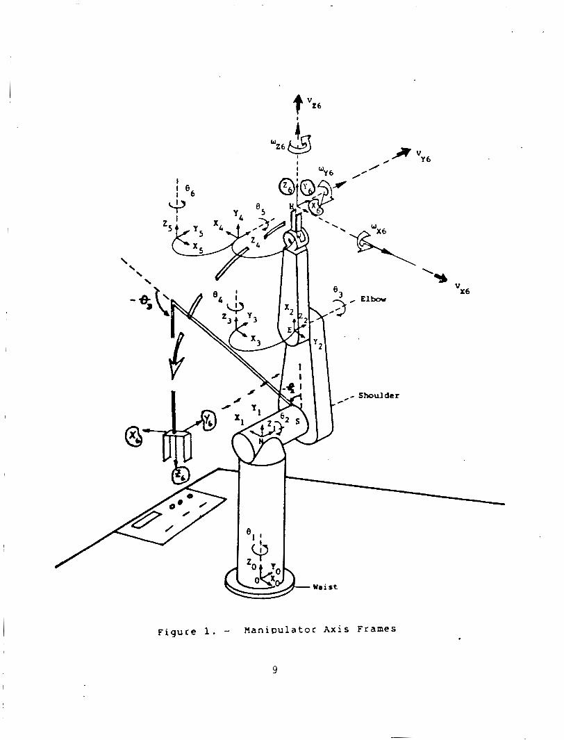
The o b j e c t i v e o f bo th methods i s t o r e s o l v e t h e t h r e e dimensional l o c a t i o n o f o b j e c t s hav ing p lanar o r min ima l ly curved surfaces r e l a t i v e t o the camera's a x i s frame. cussion, i s de f ined i n f i g u r e 1. It i s r o t a t i o n a l l y c o i n c i d e n t w i t h the frame o f the m a n i p u l a t o r ' s end e f f e c t o r , b u t t r a n s l a t i o n a l l y o f f s e t by (-15, 80, -190) m i l l i m e t e r s ( f i g u r e 1). Also, equat ions are presented i n s u f f i c i e n t d e t a i l t o a l l o w implementation, b u t are summarized w i t h o u t ex tens ive d e r i - va t ion . equat ion development.
The camera's a x i s frame, f o r t h e purpose o f the f o l l o w i n g d i s -
A complete re ference l i s t i s prov ided f o r f u r t h e r i n v e s t i g a t i o n of
The quadrangle p r o j e c t i o n method determines the l o c a t i o n and o r i e n t a t i o n of a p l a n a r o r near-planar o b j e c t from any f o u r p o i n t s on the o b j e c t t h a t descr ibe a quadrangle. the o p t i c a l parameters o f the lens/camera system, the r o t a t i o n a l and t rans- l a t i o n a l displacements between the o b j e c t and camera can be un ique ly determined. Hung e t a1 [4] prove t h a t t h e r e ex i ,s ts a unique vector , K, which r e l a t e s the t a r g e t quadrangle and i t s image such t h a t
Given the i n t e r - v e r t e x d is tances o f the quadrangle and
where < I > i s t h e quadrangle <IO, 11, 12, I 3 > t h a t i s the p r o j e c t i o n of the t a r g e t quadrangle <TO, T1, T2, T3> on the image p lane ( f i g u r e 2). T j ( j = 0,1,2,3) o f the quadrangle <T> i s a th ree component vec tor ( t j x , t j y , t j z ) represent ing the t h r e e dimensional l o c a t i o n o f the ver tex. Each ver tex I j ( j = 0,1,2,3) o f the quadrangle < I > i s a t h r e e component v e c t o r ( i j x , i j y , i j z ) represent ing the two dimensional l o c a t i o n o f the t a r g e t ' s p r o j e c t i o n on the image p lane and t h e distanc:e o f the image p lane from the camera ( i .e. t h e focal l e n g t h o f the l e n s ) . t h e f o l l o w i n g system o f equat ions:
Each ver tex
The K vector , (kO, k l , k2, k3), can be found u s i n g
I 3 = (kO/k3 1 ( 1-a1 pha-beta 1 ( IO) + ( k l / k 3 1 (a1 pha) ( I1 1 + (k2/k3 ( b e t a ( I2 1 ( 2 )
which can be so lved f o r kO/k3, k l / k3 , and k2/k3. The component k3 i s computed from:
2
k3 = / / T O - T3 / (kO/k3)(1 - alpha - b e t a I ( I 0 ) - 1311 I I II ( 3 )
For each probable t a r g e t i t i s necessary t o determine and s p e c i f y the alpha and be ta parameters based upon t h e i n t e r - v e r t e x d is tances o f the t a r g e t quadrangle. L e t PO, P1, P2 and P3 be the two dimensional coord inates o f the t a r g e t quadran- g l e ' s v e r t i c e s r e l a t i v e t o t h e t a r g e t ' s re ference frame. Then:
where
This i n f o r m a t i o n i s s u f f i c i e n t t o so lve f o r the th ree dimensional p o s i t i o n s o f the t a r g e t quadrangle v e r t i c e s r e l a t i v e t o the camera frame. The quadrangle o r i e n t a t i o n , descr ibed by the normal t o the plane occupied by the quadrangle, i s determined by s u b s t i t u t i n g the coord inates o f any th ree v e r t i c e s i n t o t h e general equat ion o f t h e plane. S o l v i n g the system o f equat ions g ives t h e f o l l o w i n g e x p l i c i t expressions f o r the o r i e n t a t i o n vector i n terms o f t h e quadrangle v e r t i c e s d e r i v e d above:
where ( 5 )
D(T) = ( tOX)( ( t l y ) ( t Z Z ) - ( t l z ) ( t Z y ) ) + ( t O y ) ( ( t l z ) ( t Z x ) - ( t l x ) ( t 2 z ) ) + ( t o 2 1 ( ( t l x 1 ( t 2y 1 - ( t l y 1 ( t 2x 1 1
and Ax, Ay, and Az are determined from A X ' , Ay', and A z ' by n o r m a l i z i n g by the magnitude o f t h e v e c t o r (AX' , Ay', Az ' ) . Th is vec tor a long w i t h t h r e e o t h e r s comprise an homogeneous t rans form m a t r i x c a l l e d i n NSAP m a t r i x C71, C81. Th is m a t r i x complete ly descr ibes the t a r g e t ' s l o c a t i o n i n the camera's a x i s frame. The approach vec tor (Ax, Ay, Az) i s the o r i e n t a t i o n vector der ived above. The s l i d i n g vec tor (Sx, Sy, Sz) i s r e l a t e d t o the s lope o f the base o f t h e quadran- g l e w i t h respec t t o the camera frame. components o f the vector , T1 - TO, normal ized by i t s length. The vec tor , (Nx, Ny, Nz) , i s the cross produc t o f the approach and s l i d i n g vec tors . The p o s i t i o n vector , (Px, Py, Pz) , i s s imply the components of the s e l e c t e d p o i n t o f approach on the t a r g e t quadrangle. commonly chosen.
I t i s composed o f the x, y, and z
The i n t e r s e c t i o n o f the d iagonals i s
The second method i s based on the e l a s t i c matching C91 approach t o p a t t e r n r e c o g n i t i o n and has a p p l i c a t i o n t o shape decomposit ion, o b j e c t r e c o g n i t i o n , and o b j e c t l o c a t i o n . It i s an adapt ion o f the l i n e a r programming technique o f goal p r o g r a m i n g t o the n o n l i n e a r problem of e l a s t i c matching C61. e l a s t i c matching can be exp la ined by e n v i s i o n i n g a t ransparent re fe rence image
Conceptual ly,
3
o v e r l a y i n g a goal image. The re fe rence image i s then warped o r d i s t o r t e d t o conform t o the goal image by l o c a l l y matching corresponding reg ions i n the two images. The re fe rence image i s a f l e x i b l e template t h a t i s modelled as a system o f equat ion p a i r s where each equat ion p a i r represents a l i n e a r combi- n a t i o n o f p a t t e r n s t h a t a p o i n t i n the re fe rence image can descr ibe i n moving t o a p o i n t i n the goal image ( f i g u r e 3) . The amount o f d isplacement each p a t t e r n c o n t r i b u t e s t o the d i s t o r t i o n i s determined by i d e n t i f y i n g the values o f the parameters, A i and B i , assoc iated w i t h each o f the d i s t o r t i o n pa t te rns . The parameter values are d e r i v e d by m i n i m i z i n g the absolute d i f f e r e n c e s between corresponding reference and goal image p o i n t s w i t h o u t v i o l a t i n g the p a t t e r n c o n s t r a i n t s . T h i s type o f problem i s e a s i l y modelled mathemat ica l ly u s i n g the 1 i n e a r programming technique o f goal programming [lo]. The computat ional procedure o f the Simplex A lgor i thm m o s t e f f i c i e n t l y resolves the opt imal values of the model I s parameters.
The e l a s t i c matching technique has been used t o recognize o b j e c t s w i t h p l a n a r o r min ima l ly curvet! sur faces and t o l o c a t e them i n t h r e e dimensions [6]. The d iscuss ion here concerns the l o c a t i o n o f an ob jec t , once i t has been recognized, and f o u r o r more p o i n t s o f known geometric r e l a t i o n s h i p e x t r a c t e d from i t s image. The objec:t i s represented i n a data base as a reasonably convex s e t o f p o i n t s whose! values descr ibe the o b j e c t i n an o r i e n t a t i o n and l o c a t i o n normal t o and centered on the o p t i c a l a x i s o f the camera, and a d i s t a n c e equal t o t h e foca:l l e n g t h o f the lens, a long the a x i s . Th is i s the '
d i s t o r t e d reference image used t o match the e x t r a c t e d image. The t h r e e dimensional l o c a t i o n o f the t a r g e t o b j e c t can be der ived from the parameters, A0 through A3 and BO through 83. Equat ions ( 6 ) through ( 9 ) show the geometr ic s i g n i f i c a n c e o f the parameters.
A0 = X ' - X : t r a n s l a t i o n ( 6 )
BO = Y ' - Y
A 1 = - ( 1 - g a i n ) : zoom ( 7 )
B 1 = -(1 - g a i n ) ga in = X ' / X o r Y ' / Y
A2-= ( X ' - X)/Y : r o t a t i o n about z ( t h e (8 )
82 = (Y ' - Y)/X o p t i c a l a x i s
A3 = -(1 - gain) /Y : perspec t ive i n f o r m a t i o n ( 9 )
8 3 = -(1 - gain) /X
Parameters A4, AS, 84, and BS y i e l d shape i n f o r m a t i o n and are used t o a i d o b j e c t r e c o g n i t i o n [SI. Equat ions (10) through (121, which are based on p r o p e r t i e s o f t h e p e r s p e c t i v e t rans format ion 1113, show the parameters ' r e l a t i o n s h i p t o the range, r o t a t i o n about y, and r o t a t i o n about x r e s p e c t i v e l y of the t a r g e t o b j e c t r e l a t ' i v e t o the camera's a x i s system.
.
range = ((f)(Wo)(Z - Al))/((l - Al)(Ws)) (10)
4
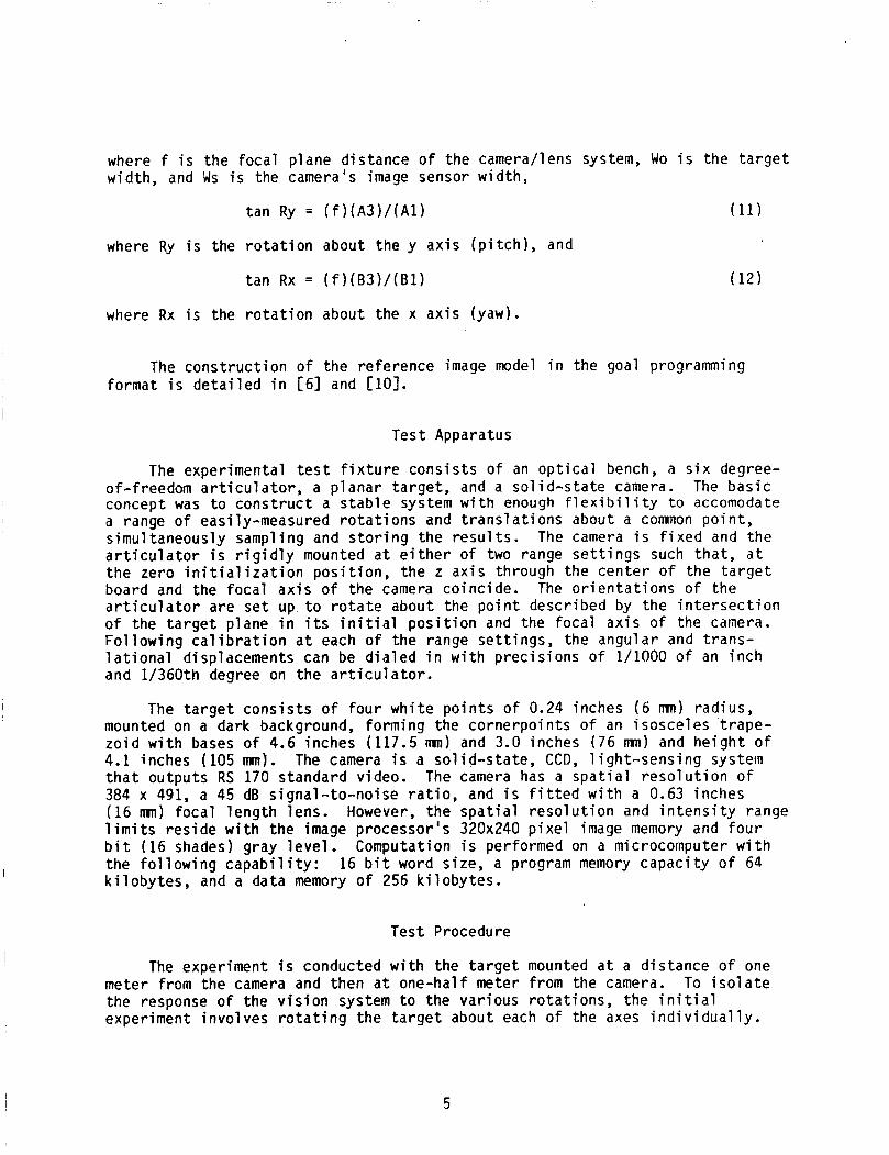
where f i s the foca l p lane d is tance o f the camera/lens system, Wo i s the t a r g e t width, and iJs i s the camera's image sensor width,
tan Ry = ( f ) ( A 3 ) / ( A 1 ) (11)
where Ry i s the r o t a t i o n about the y a x i s ( p i t c h ) , and
tan Rx = ( f ) ( B 3 ) / ( B l ) (12)
where Rx i s the r o t a t i o n about the x a x i s (yaw).
The c o n s t r u c t i o n of the re fe rence image model i n the goal programming format i s d e t a i l e d i n [6] and [ l o ] .
Test Apparatus
The exper imental t e s t f i x t u r e c o n s i s t s o f an o p t i c a l bench, a s i x degree- of-freedom a r t i c u l a t o r , a p l a n a r t a r g e t , and a s o l i d - s t a t e camera. The b a s i c concept was t o c o n s t r u c t a s t a b l e system w i t h enough f l e x i b i l i t y t o accomodate a range o f easi ly-measured r o t a t i o n s and t r a n s l a t i o n s about a common p o i n t , s imul taneously sampling and s t o r i n g the r e s u l t s . The camera i s f i x e d and t h e a r t i c u l a t o r i s r i g i d l y mounted a t e i t h e r o f two range s e t t i n g s such t h a t , a t t h e zero i n i t i a l i z a t i o n p o s i t i o n , the z a x i s through the c e n t e r o f the t a r g e t board and the foca l a x i s o f the camera co inc ide . The o r i e n t a t i o n s o f the a r t i c u l a t o r are s e t up t o r o t a t e about the p o i n t descr ibed by the i n t e r s e c t i o n o f the t a r g e t p lane i n i t s i n i t i a l p o s i t i o n and the foca l a x i s o f the camera. F o l l o w i n g c a l i b r a t i o n a t each o f the range s e t t i n g s , the angular and t rans- l a t i o n a l displacements can be d i a l e d i n w i t h p r e c i s i o n s o f 1/1000 o f an i n c h and 1/360th degree on the a r t i c u l a t o r .
The t a r g e t c o n s i s t s o f f o u r w h i t e p o i n t s o f 0.24 inches ( 6 mn) rad ius, mounted on a dark background, forming the cornerpo in ts o f an isosce les t r a p e - z o i d w i t h bases o f 4.6 inches (117.5 mn) and 3.0 inches (76 nm) and h e i g h t o f 4.1 inches (105 mm). The camera i s a s o l i d - s t a t e , CCD, l i g h t - s e n s i n g system t h a t outputs RS 170 s tandard video. 384 x 491, a 45 dB s igna l - to -no ise r a t i o , and i s f i t t e d w i t h a 0.63 inches (16 mn) f o c a l l e n g t h lens. However, the s p a t i a l r e s o l u t i o n and i n t e n s i t y range l i m i t s r e s i d e w i t h t h e image processor 's 320x240 p i x e l image memory and f o u r b i t (16 shades) gray l e v e l . the f o l l o w i n g c a p a b i l i t y : 16 b i t word s ize, a program memory c a p a c i t y o f 64 k i l o b y t e s , and a data memory o f 256 k i l o b y t e s .
The camera has a s p a t i a l r e s o l u t i o n o f
Computation i s performed on a microcomputer w i t h
Test Procedure
The experiment i s conducted w i t h the t a r g e t mounted a t a d is tance o f one meter from the camera and then a t one-hal f meter from the camera. To i s o l a t e the response o f the v i s i o n system t o the var ious r o t a t i o n s , the i n i t i a l experiment i n v o l v e s r o t a t i n g t h e t a r g e t about each o f the axes i n d i v i d u a l l y .
5
For each ax is , t h e target . i s r o t a t e d through a range o f plus-or-minus 60 degrees, beyond which process ing becomes i m p r a c t i c a l . The r o t a t i o n s a r e sampled a t 10-degree i n t e r v a l s and the t r a n s l a t i o n s a t .025 inches ( 1 mn) i n t e r v a l s over a range o f plus-or-minus 0.3 inches (7.6 mm). The t r a n s l a t i o n s are taken a t these i n t e r v a l s t o g i v e an i n d i c a t i o n o f the response t o t rans- 1 a t i onal d i s p l acements of 1-mi 11 imeter i ncrements. The exper iment i s repeated a t one-half meter, bo th t o t e s t the response o f the system t o v a r i a t i o n i n image and t a r g e t p o i n t s ize, and t o i n d i c a t e response t o a l a r g e sca le d i f f e r - e n t i a l t r a n s l a t i o n . The t a r g e t ' s p o i n t coord inates are sampled 30 t imes f o r each displacement and processed by both l o c a t i o n a lgor i thms. The t r a n s l a t i o n a l and r o t a t i o n a l s o l u t i o n s o f both a lgor i thms are then processed t o f i n d the mean, standard dev ia t ion , and conf idence l i m i t s o f each c a l c u l a t e d d i s - placement.
I n o rder t o determine the e f f e c t o f r o t a t i o n a l and t r a n s l a t i o n a l e r r o r s i n combination, an exper iment i n v i s i o n d r i v e n a c q u i s i t i o n o f a c y l i n d r i c a l s t r u t was conducted. The camera, mounted on t h e end e f f e c t o r o f a s i x degree-of- freedom manipu la to r ( f i g u r e 11, and the s t r u t were placed i n random o r i e n - t a t i o n s r e l a t i v e t o each o ther . The l o c a t i o n a lgor i thms were then used t o c o r r e c t the t r a j e c t o r y o f the end e f f e c t o r and update the o r i e n t a t i o n and l o c a t i o n o f the s t r u t u n t i l the s t r u t was acqui red by the end e f f e c t o r . Each a c q u i s i t i o n sequence was i n i t i a t e d a t a d is tance o f approx imate ly 0.75 meters 5etween the camera l e n s and the s t r u t .
CONCLUSION AND RESULTS
Two f o u r - p o i n t l o c a t i o n a lgor i thms have been discussed and an exper iment Resul ts a r e d isp layed i n t h e t o determine t h e i r accuracy has been descr ibed.
graphs o f f i g u r e s ( 4 ) and ( 5 ) . The displacement q u a n t i t i e s a r e presented i n degrees and inches because the a r t i c u l a t o r was gradated i n those u n i t s o f mea s u remen t .
The r e s u l t s obta ined con ta in the e f f e c t s o f e r r o r s i nhe ren t i n t h e v i s i o n system and the t e s t apparatus. r e s o l u t i o n o f t h e image a c q u i s i t i o n and process ing subsystem, and the s i z e of the t a r g e t p o i n t s . c o n t r o l l e d by t h e 0.35 inches (8.8 mn) by 0.26 inches (6.6 mn) image sensor area and the 320 h o r i z o n t a l by 240 v e r t i c a l p i x e l a r r a y o f the image pro- c e s s o r ' s image memory. inches (.0275 mn) change i n sensor image corresponds t o a 0.03 inches (0.8 mm) u n c e r t a i n t y o f t a r g e t p o i n t l o c a t i o n i n the x-y plane, g iven a t a r g e t d is tance of 0.5 meter and a l e n s f o c a l l e n g t h o f 0.63 inches (16 mm). Range u n c e r t a i n t y i s 0.13 inches (3.3 mnl and r o t a e i o n u n c e r t a i n t y about the x and y axes i s 1.8 degrees w i t h the t a r g e t used. R o t a t i o n about the z a x i s i s s e n s i t i v e t o 0.44 degrees o f displacement.
The pr imary e r r o r sources a r e t h e s p a t i a l
The u n c e r t a i n t y o f the l o c a t i o n o f a t a r g e t p o i n t i s
These dimensions determine t h a t a one-pixel o r 0.001
The quadrangular p r o j e c t i o n technique produces c o n s i s t e n t r e s u l t s accura te t o the i n h e r e n t e r r o r o f the system. The averaged absolute t r a n s l a t i o n a l
6
e r r o r s are 0.072 inches (1.8 mn) and 0.012 inches (0.3 m) a t 1.0 and 0.5 meters r e s p e c t i v e l y , and the mean absolute r o t a t i o n a l e r r o r s are 0.86 and 0.44 degrees a t those d is tances. The instantaneous accurac ies can be expected t o f a l l w i t h i n the conf idence l i m i t s computed f o r each displacement. The wors t case standard d e v i a t i o n f o r r o t a t i o n a l displacements i s 1.96 degrees a t 0.5 meter and 2.8 degrees a t 1.0 meter. The maximum standard d e v i a t i o n s f o r t rans- l a t i o n a l displacements are 0.02 inches (0.51 mn) a t 0.5 meter and 0.06 inches (1.5 mn) a t 1.0 meter.
The e l a s t i c matching technique data was c o l l e c t e d a t the 0.5 meter d i s t a n c e only . The mean r o t a t i o n a l e r r o r u s i n g the e l a s t i c matcher was 3.3 degrees and the worst case standard d e v i a t i o n was 4.5. There were d i f f e r e n c e s between the actual and computed r o t a t i o n s o f as much as 7 degrees. The t rans- l a t i o n s computed u s i n g the e l a s t i c matcher were as accurate as those der ived u s i n g the quadrangular p r o j e c t i o n technique. The pr imary reason f o r t h e incons is tency o f the r o t a t i o n a l performance o f the e l a s t i c matcher i s the small number o f p o i n t s i n v o l v e d i n the match. The matcher a c t u a l l y approximated the quadrangle q u i t e w e l l , w i t h each model p o i n t d isp laced t o w i t h i n two o r t h r e e p i x e l s o f the ac tua l image p o i n t , b u t d i d n o t always i d e n t i f y t h e appropr ia te parameter f o r the geometric cond i t ion . Const ra in ts were l a c k i n g t o ensure a unique solution. The consistency o f the matcher i s directly proportional to the number o f p o i n t s be ing matched, c o n s i s t e n t l y demonstrat ing r o t a t i o n a l accuracy when 16 p o i n t s a re be ing matched. It a l s o performed w e l l i n a manipu- l a t o r servo experiment [6] which i n v o l v e d accurate p o s i t i o n i n g o f the manipu- l a t o r t o o l w i t h respec t t o a rec tangu lar t a r g e t .
Both techniques have success fu l l y d r i v e n an end e f f e c t o r t o acqu i re a t a r g e t t o an accuracy o f 0.5 degree r o t a t i o n a l e r r o r and 0.02 i n c h (.5 mm) t r a n s l a t i o n a l e r r o r a t a c q u i s i t i o n . This accuracy i s c o n s i s t e n t regard less o f the r e l a t i v e o r i e n t a t i o n o f the camera/end e f f e c t o r and the t a r g e t a t t h e i n i t i a t i o n o f t h e a c q u i s i t i o n sequence. Combinations o f r o t a t i o n a l d i s - placement have l i t t l e e f f e c t on the u l t i m a t e accuracy o f these techniques when they a r e used i n a servo mode. t o t e s t the a l g o r i t h m accuracies a t both one meter and a t one-hal f meter.
A more r i g o r o u s exper iment i s now be ing devised
The quadrangular p r o j e c t i o n method i s a more c o n s i s t e n t l o c a t i o n technique than the e l a s t i c matcher when the t a r g e t c o n s i s t s o f f o u r p o i n t s . t o w i t h i n 1 degree and 0.1 i n c h (2.54 m i l l i m e t e r s ) a t 1 meter a re more than s u f f i c i e n t f o r accurate c losed- loop c o n t r o l o f a manipulator . servo mode, the measurement accuracy and noise immunity o f both methods increases as the manipulator approaches the t a r g e t .
Accuracies
When used i n a
7
REFERENCES
1. Myers, D. R., Juberts, M., and Leake, ,$. A.: "Enhanced Telemanipulator Operat ion us ing a Passive V is ion System," i n Proceedings o f IEEE Conference on Man and Cybernet ics, Tucson, Arizona, Nov. 1985.
2. Hara l i ck , R. M., "Determining Camera Parameters from the Perspec t ive P r o j e c t i o n o f a Rectangle," Technical Note, V i r g i n i a Po ly techn ic I n s t i t u t e , Blacksburg, V i r g i n i a , June 1982.
Wolfe, W. J., "A Vis ion System f o r Recognizing and Track ing Known Objects," i n Proceedings o f JPL Space Te le robo t i cs Workshop, Pasadena, C a l i f o r n i a , Janudry 20-22, 1987.
3 .
4 . Hung, Y., Yeh, P.., Harwood, D., "Passive Ranging t o Known Planar P o i n t Sets," Proceedings o f the IEEE I n t e r n a t i o n a l Conference on Robot ics and Automation, pp. 80-85, 1985.
5. Goode, P. W., Corn i l s , K.: RMonovision Techniques f o r Telerobots," i n Proceedings o f JPL Space Te le robo t i cs Workshop, Pasadena, C a l i f o r n i a , January 20-22, 1987.
Vision," Proceedings of the A I A A Guidance, Navigat ion, and Contro l Conference, August, 1986.
6. Goode, P. W.: "A M u l t i f u n c t i o n Recogn i t ion Operator f o r Te le rooo t i c
7. Paul, R. P.: Robot Man ipu la to rs : Mathematics, Programming, and
8. Lee, C.S.G.: "Robot Arm Kinematics, Dynamics, and Contro l ,I' IEEE
Cont ro l , M IT Press, Cambridge, Massachusetts, 1981.
Computer, Vol 15, No. 12, December 1982.
9. Widrow, B.: "The Rubber Mask Technique," Pa t te rn Recogni t ion, Vol 5, 1973, pp. 175-211.
10. H i l l i e r , F.. S. and Lieberman, G. J . , I n t r o d u c t i o n t o Operat ions Research, 3 rd e d i t i o n , Holden-Day, San Francisco, 1980.
11. H a r a l i c k , R. M., "Using Perspec t ive Transformat ions i n Scene Analysis," Computer Graphics and Image Processing, 13, 191-221, 1980.
8
k wZ6 &
I I
\ \
Shoulder
Figure 1. - Hanipulator A x i s Frames
9
Figure 2 . - Ouadrangle P r o j e c t i o n
: Translat ion Ao' Bo Al, B, : Cain
A2, B2
A3, 8)
A4, B4
%. Bs
f ( a . y) : -1 fwth
: Rotation f n X - Y p l r w
: P e n p e c t i n o f t r i a n g u l a r sham i n f o r m t i o n