
LOCATION OF PLANAR TARGETS I N THREE SPACE FROM MONOCULAR IMAGES
K a r i n C o r n i l s and P lesent W. Goode NASA Langley Research Center
Presented a t t he 1987 Goddard Conference on Space App l i ca t i ons o f A r t i f i c i a l I n t e l l i g e n c e ( A I ) and Robo t i cs
1
Greenbel t, Mary1 and May 13-14, 1987
( W A S A - i M - 1 0 1 8 6 d ) L ' ICATTON q F PLANAS T A P G F T S I N T h P t C ';PACT FRqM IYONRCIILAR I Y A G t S ( N A S A . L a n n l e y Hsseilrch Center) 13 p CSLL 039
N89-29991
uncl as G 3 / 6 3 0233126
https://ntrs.nasa.gov/search.jsp?R=19890020620 2018-07-25T14:51:45+00:00Z

L
LOCATION OF PLANAR TARGETS I N THREE SPACE FROM MONOCULAR IMAGES
BY
K a r i n Corni 1 s Plesent W. Goode
NASA Langley Research Center
ABSTRACT
Many pieces o f e x i s t i n g and proposed space hardware t h a t would be t a r g e t s
Examples i n c l u d e the b ios tack modules on t h e Long Dura t ion Exposure o f i n t e r e s t f o r a t e l e r o b o t can be represented as p lanar o r near-p lanar surfaces. F a c i l i t y , the panels on So lar Max, l a r g e diameter s t r u t s , and r e f u e l i n g receptac les . w i t h s u f f i c i e n t accuracy are t h e r e f o r e worth developing.
Robust and tempora l ly e f f i c i e n t methods f o r l o c a t i n g such o b j e c t s
Two techniques t h a t d e r i v e the o r i e n t a t i o n and l o c a t i o n o f an o b j e c t f rom i t s monocular image a r e discussed and the r e s u l t s o f experiments performed t o determine t rans1 a t i o n a l and r o t a t i o n a l accuracy a r e presented. Both the "quadrangle p r o j e c t i o n " and " e l a s t i c matching" techniques e x t r a c t t h r e e space i n f o r m a t i o n u s i n g a minimum o f f o u r i d e n t i f i a b l e t a r g e t p o i n t s and t h e p r i n c i - p l e s o f t h e perspec t ive t rans format ion . convex polygon whose geometric c h a r a c t e r i s t i c s a re p r e s p e c i f i e d i n a data base.
The s e l e c t e d p o i n t s must descr ibe a
The r o t a t i o n a l and t r a n s l a t i o n a l accuracy o f both techniques was t e s t e d a t v a r i o u s ranges. i n v o l v e d i n a t y p i c a l t e l e r o b o t t a r g e t a c q u i s i t i o n task. Both techniques determined t a r g e t l o c a t i o n t o an accuracy s u f f i c i e n t f o r c o n s i s t e n t and e f f i c i e n t a c q u i s i t i o n by the t e l e r o b o t .
T h i s experiment i s , r e p r e s e n t a t i @ o f the sensing requirements
INTRODUCTION
Simple and computa t iona l l y e f f i c i e n t methods f o r l o c a t i n g t a r g e t s i n 3-space are necessary f o r rea l - t ime automat ic c o n t r o l o f manipulators . c l a s s o f techniques hav ing a p p l i c a t i o n t o a broad range o f sensor-based c o n t r o l problems i s t h a t o f f o u r p o i n t l o c a t i o n a lgor i thms. p o i n t s on space hardware t o enhance i t as a manipulator t a r g e t i s f e a s i b l e . The t a r g e t s are man made o b j e c t s whose components and s t r u c t u r a l measurements a re well-documented. Typ ica l p o i n t s t h a t cou ld be e x t r a c t e d a r e those t h a t can be der ived from the moments o f the p lanar o r near-planar sur faces o f b o l t heads, f u e l i n g receptac les and large-diameter s t r u t s . The p e r s p e c t i v e pro- j e c t i o n s o f these p o i n t s through a lens system onto an image sensor can be compared t o t h e i r known in te rd is tances , and the l o c a t i o n o f the o b j e c t on which they l i e r e l a t i v e t o the sensor can be determined. both the referenced s tud ies and i n t h i s study i s the s o l i d - s t a t e camera.
One
P l a c i n g i d e n t i f i a b l e
The image sensor used i n

Previous work inc ludes a c losed form s o l u t i o n developed by H a r a l i c k C11 t h a t assumes a r e c t a n g u l a r c o n f i g u r a t i o n o f the f o u r p o i n t s . Implementation o f H a r a l i c k ' s A l g o r i t h m i n rea l - t ime r o b o t v i s i o n systems has been accomplished a t the NASA Langley Research Center, The Nat iona l Bureau o f Standards, and M a r t i n M a r i e t t a Denver Aerospace. Resul ts u s i n g t h i s a l g o r i t h m were repor ted by Myers e t a1 [Z ] and Wolfe e t a1 C31. Hung e t a1 C41 developed an a l g o r i t h m t h a t d i r e c t l y computes t h e 3-D coord inates o f the v e r t i c e s o f a quadrangle r e l a t i v e t o the camera frame. Goode and C o r n i l s C5l adapted the theory developed by Hung, Yeh, and Harwood t o t h e r e a l - t i m e c o n t r o l o f manipulators . An a l g o r i t h m developed by Goode C61 u s i n g f o u r o r more p o i n t s t o approximate a convex shape t o determine a t a r g e t ' s o r i e n t a t i o n and l o c a t i o n was a p p l i e d t o c losed- loop man ipu la to r c o n t r o l . Th is paper summarizes the techniques developed i n C51 and [6], and r e p o r t s the r e s u l t s o f an experiment designed t o determine the r o t a t i o n a l and t rans1 a t i o n a l accuracy o f the two methods.
Two Four-Point A1 g o r i thms
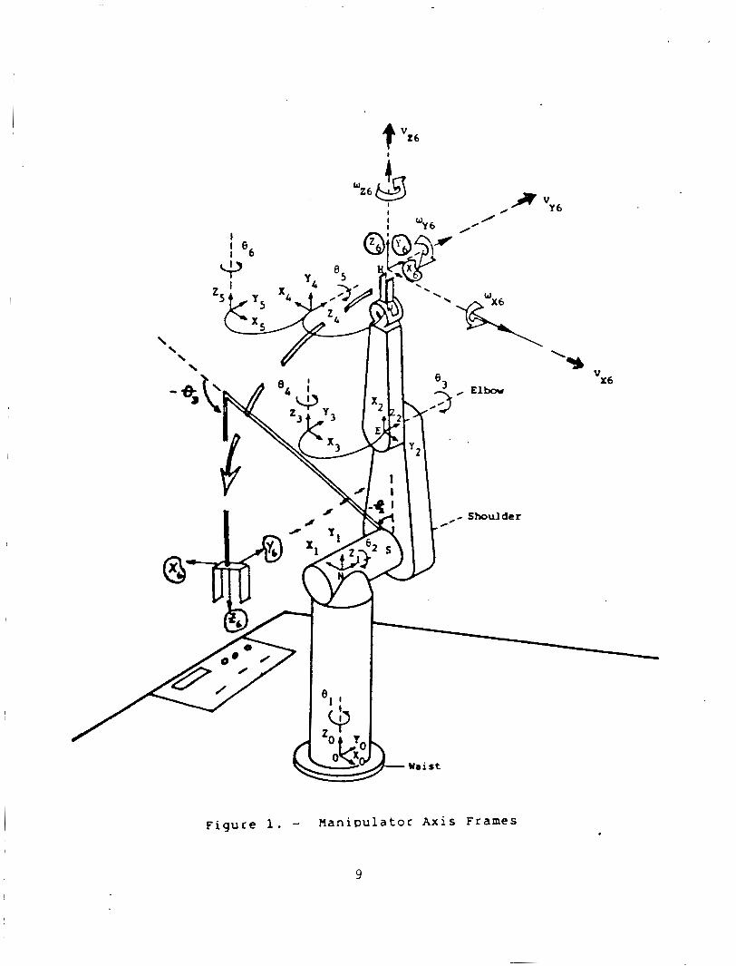
The o b j e c t i v e o f bo th methods i s t o r e s o l v e t h e t h r e e dimensional l o c a t i o n o f o b j e c t s hav ing p lanar o r min ima l ly curved surfaces r e l a t i v e t o the camera's a x i s frame. cussion, i s de f ined i n f i g u r e 1. It i s r o t a t i o n a l l y c o i n c i d e n t w i t h the frame o f the m a n i p u l a t o r ' s end e f f e c t o r , b u t t r a n s l a t i o n a l l y o f f s e t by (-15, 80, -190) m i l l i m e t e r s ( f i g u r e 1). Also, equat ions are presented i n s u f f i c i e n t d e t a i l t o a l l o w implementation, b u t are summarized w i t h o u t ex tens ive d e r i - va t ion . equat ion development.
The camera's a x i s frame, f o r t h e purpose o f the f o l l o w i n g d i s -
A complete re ference l i s t i s prov ided f o r f u r t h e r i n v e s t i g a t i o n of
The quadrangle p r o j e c t i o n method determines the l o c a t i o n and o r i e n t a t i o n of a p l a n a r o r near-planar o b j e c t from any f o u r p o i n t s on the o b j e c t t h a t descr ibe a quadrangle. the o p t i c a l parameters o f the lens/camera system, the r o t a t i o n a l and t rans- l a t i o n a l displacements between the o b j e c t and camera can be un ique ly determined. Hung e t a1 [4] prove t h a t t h e r e ex i ,s ts a unique vector , K, which r e l a t e s the t a r g e t quadrangle and i t s image such t h a t
Given the i n t e r - v e r t e x d is tances o f the quadrangle and
where < I > i s t h e quadrangle <IO, 11, 12, I 3 > t h a t i s the p r o j e c t i o n of the t a r g e t quadrangle <TO, T1, T2, T3> on the image p lane ( f i g u r e 2). T j ( j = 0,1,2,3) o f the quadrangle <T> i s a th ree component vec tor ( t j x , t j y , t j z ) represent ing the t h r e e dimensional l o c a t i o n o f the ver tex. Each ver tex I j ( j = 0,1,2,3) o f the quadrangle < I > i s a t h r e e component v e c t o r ( i j x , i j y , i j z ) represent ing the two dimensional l o c a t i o n o f the t a r g e t ' s p r o j e c t i o n on the image p lane and t h e distanc:e o f the image p lane from the camera ( i .e. t h e focal l e n g t h o f the l e n s ) . t h e f o l l o w i n g system o f equat ions:
Each ver tex
The K vector , (kO, k l , k2, k3), can be found u s i n g
I 3 = (kO/k3 1 ( 1-a1 pha-beta 1 ( IO) + ( k l / k 3 1 (a1 pha) ( I1 1 + (k2/k3 ( b e t a ( I2 1 ( 2 )
which can be so lved f o r kO/k3, k l / k3 , and k2/k3. The component k3 i s computed from:
2

k3 = / / T O - T3 / (kO/k3)(1 - alpha - b e t a I ( I 0 ) - 1311 I I II ( 3 )
For each probable t a r g e t i t i s necessary t o determine and s p e c i f y the alpha and be ta parameters based upon t h e i n t e r - v e r t e x d is tances o f the t a r g e t quadrangle. L e t PO, P1, P2 and P3 be the two dimensional coord inates o f the t a r g e t quadran- g l e ' s v e r t i c e s r e l a t i v e t o t h e t a r g e t ' s re ference frame. Then:
where
This i n f o r m a t i o n i s s u f f i c i e n t t o so lve f o r the th ree dimensional p o s i t i o n s o f the t a r g e t quadrangle v e r t i c e s r e l a t i v e t o the camera frame. The quadrangle o r i e n t a t i o n , descr ibed by the normal t o the plane occupied by the quadrangle, i s determined by s u b s t i t u t i n g the coord inates o f any th ree v e r t i c e s i n t o t h e general equat ion o f t h e plane. S o l v i n g the system o f equat ions g ives t h e f o l l o w i n g e x p l i c i t expressions f o r the o r i e n t a t i o n vector i n terms o f t h e quadrangle v e r t i c e s d e r i v e d above:
where ( 5 )
D(T) = ( tOX)( ( t l y ) ( t Z Z ) - ( t l z ) ( t Z y ) ) + ( t O y ) ( ( t l z ) ( t Z x ) - ( t l x ) ( t 2 z ) ) + ( t o 2 1 ( ( t l x 1 ( t 2y 1 - ( t l y 1 ( t 2x 1 1
and Ax, Ay, and Az are determined from A X ' , Ay', and A z ' by n o r m a l i z i n g by the magnitude o f t h e v e c t o r (AX' , Ay', Az ' ) . Th is vec tor a long w i t h t h r e e o t h e r s comprise an homogeneous t rans form m a t r i x c a l l e d i n NSAP m a t r i x C71, C81. Th is m a t r i x complete ly descr ibes the t a r g e t ' s l o c a t i o n i n the camera's a x i s frame. The approach vec tor (Ax, Ay, Az) i s the o r i e n t a t i o n vector der ived above. The s l i d i n g vec tor (Sx, Sy, Sz) i s r e l a t e d t o the s lope o f the base o f t h e quadran- g l e w i t h respec t t o the camera frame. components o f the vector , T1 - TO, normal ized by i t s length. The vec tor , (Nx, Ny, Nz) , i s the cross produc t o f the approach and s l i d i n g vec tors . The p o s i t i o n vector , (Px, Py, Pz) , i s s imply the components of the s e l e c t e d p o i n t o f approach on the t a r g e t quadrangle. commonly chosen.
I t i s composed o f the x, y, and z
The i n t e r s e c t i o n o f the d iagonals i s
The second method i s based on the e l a s t i c matching C91 approach t o p a t t e r n r e c o g n i t i o n and has a p p l i c a t i o n t o shape decomposit ion, o b j e c t r e c o g n i t i o n , and o b j e c t l o c a t i o n . It i s an adapt ion o f the l i n e a r programming technique o f goal p r o g r a m i n g t o the n o n l i n e a r problem of e l a s t i c matching C61. e l a s t i c matching can be exp la ined by e n v i s i o n i n g a t ransparent re fe rence image
Conceptual ly,
3

o v e r l a y i n g a goal image. The re fe rence image i s then warped o r d i s t o r t e d t o conform t o the goal image by l o c a l l y matching corresponding reg ions i n the two images. The re fe rence image i s a f l e x i b l e template t h a t i s modelled as a system o f equat ion p a i r s where each equat ion p a i r represents a l i n e a r combi- n a t i o n o f p a t t e r n s t h a t a p o i n t i n the re fe rence image can descr ibe i n moving t o a p o i n t i n the goal image ( f i g u r e 3) . The amount o f d isplacement each p a t t e r n c o n t r i b u t e s t o the d i s t o r t i o n i s determined by i d e n t i f y i n g the values o f the parameters, A i and B i , assoc iated w i t h each o f the d i s t o r t i o n pa t te rns . The parameter values are d e r i v e d by m i n i m i z i n g the absolute d i f f e r e n c e s between corresponding reference and goal image p o i n t s w i t h o u t v i o l a t i n g the p a t t e r n c o n s t r a i n t s . T h i s type o f problem i s e a s i l y modelled mathemat ica l ly u s i n g the 1 i n e a r programming technique o f goal programming [lo]. The computat ional procedure o f the Simplex A lgor i thm m o s t e f f i c i e n t l y resolves the opt imal values of the model I s parameters.
The e l a s t i c matching technique has been used t o recognize o b j e c t s w i t h p l a n a r o r min ima l ly curvet! sur faces and t o l o c a t e them i n t h r e e dimensions [6]. The d iscuss ion here concerns the l o c a t i o n o f an ob jec t , once i t has been recognized, and f o u r o r more p o i n t s o f known geometric r e l a t i o n s h i p e x t r a c t e d from i t s image. The objec:t i s represented i n a data base as a reasonably convex s e t o f p o i n t s whose! values descr ibe the o b j e c t i n an o r i e n t a t i o n and l o c a t i o n normal t o and centered on the o p t i c a l a x i s o f the camera, and a d i s t a n c e equal t o t h e foca:l l e n g t h o f the lens, a long the a x i s . Th is i s the '
d i s t o r t e d reference image used t o match the e x t r a c t e d image. The t h r e e dimensional l o c a t i o n o f the t a r g e t o b j e c t can be der ived from the parameters, A0 through A3 and BO through 83. Equat ions ( 6 ) through ( 9 ) show the geometr ic s i g n i f i c a n c e o f the parameters.
A0 = X ' - X : t r a n s l a t i o n ( 6 )
BO = Y ' - Y
A 1 = - ( 1 - g a i n ) : zoom ( 7 )
B 1 = -(1 - g a i n ) ga in = X ' / X o r Y ' / Y
A2-= ( X ' - X)/Y : r o t a t i o n about z ( t h e (8 )
82 = (Y ' - Y)/X o p t i c a l a x i s
A3 = -(1 - gain) /Y : perspec t ive i n f o r m a t i o n ( 9 )
8 3 = -(1 - gain) /X
Parameters A4, AS, 84, and BS y i e l d shape i n f o r m a t i o n and are used t o a i d o b j e c t r e c o g n i t i o n [SI. Equat ions (10) through (121, which are based on p r o p e r t i e s o f t h e p e r s p e c t i v e t rans format ion 1113, show the parameters ' r e l a t i o n s h i p t o the range, r o t a t i o n about y, and r o t a t i o n about x r e s p e c t i v e l y of the t a r g e t o b j e c t r e l a t ' i v e t o the camera's a x i s system.
.
range = ((f)(Wo)(Z - Al))/((l - Al)(Ws)) (10)
4
where f i s the foca l p lane d is tance o f the camera/lens system, Wo i s the t a r g e t width, and iJs i s the camera's image sensor width,
tan Ry = ( f ) ( A 3 ) / ( A 1 ) (11)
where Ry i s the r o t a t i o n about the y a x i s ( p i t c h ) , and
tan Rx = ( f ) ( B 3 ) / ( B l ) (12)
where Rx i s the r o t a t i o n about the x a x i s (yaw).
The c o n s t r u c t i o n of the re fe rence image model i n the goal programming format i s d e t a i l e d i n [6] and [ l o ] .
Test Apparatus
The exper imental t e s t f i x t u r e c o n s i s t s o f an o p t i c a l bench, a s i x degree- of-freedom a r t i c u l a t o r , a p l a n a r t a r g e t , and a s o l i d - s t a t e camera. The b a s i c concept was t o c o n s t r u c t a s t a b l e system w i t h enough f l e x i b i l i t y t o accomodate a range o f easi ly-measured r o t a t i o n s and t r a n s l a t i o n s about a common p o i n t , s imul taneously sampling and s t o r i n g the r e s u l t s . The camera i s f i x e d and t h e a r t i c u l a t o r i s r i g i d l y mounted a t e i t h e r o f two range s e t t i n g s such t h a t , a t t h e zero i n i t i a l i z a t i o n p o s i t i o n , the z a x i s through the c e n t e r o f the t a r g e t board and the foca l a x i s o f the camera co inc ide . The o r i e n t a t i o n s o f the a r t i c u l a t o r are s e t up t o r o t a t e about the p o i n t descr ibed by the i n t e r s e c t i o n o f the t a r g e t p lane i n i t s i n i t i a l p o s i t i o n and the foca l a x i s o f the camera. F o l l o w i n g c a l i b r a t i o n a t each o f the range s e t t i n g s , the angular and t rans- l a t i o n a l displacements can be d i a l e d i n w i t h p r e c i s i o n s o f 1/1000 o f an i n c h and 1/360th degree on the a r t i c u l a t o r .
The t a r g e t c o n s i s t s o f f o u r w h i t e p o i n t s o f 0.24 inches ( 6 mn) rad ius, mounted on a dark background, forming the cornerpo in ts o f an isosce les t r a p e - z o i d w i t h bases o f 4.6 inches (117.5 mn) and 3.0 inches (76 nm) and h e i g h t o f 4.1 inches (105 mm). The camera i s a s o l i d - s t a t e , CCD, l i g h t - s e n s i n g system t h a t outputs RS 170 s tandard video. 384 x 491, a 45 dB s igna l - to -no ise r a t i o , and i s f i t t e d w i t h a 0.63 inches (16 mn) f o c a l l e n g t h lens. However, the s p a t i a l r e s o l u t i o n and i n t e n s i t y range l i m i t s r e s i d e w i t h t h e image processor 's 320x240 p i x e l image memory and f o u r b i t (16 shades) gray l e v e l . the f o l l o w i n g c a p a b i l i t y : 16 b i t word s ize, a program memory c a p a c i t y o f 64 k i l o b y t e s , and a data memory o f 256 k i l o b y t e s .
The camera has a s p a t i a l r e s o l u t i o n o f
Computation i s performed on a microcomputer w i t h
Test Procedure
The experiment i s conducted w i t h the t a r g e t mounted a t a d is tance o f one meter from the camera and then a t one-hal f meter from the camera. To i s o l a t e the response o f the v i s i o n system t o the var ious r o t a t i o n s , the i n i t i a l experiment i n v o l v e s r o t a t i n g t h e t a r g e t about each o f the axes i n d i v i d u a l l y .
5

For each ax is , t h e target . i s r o t a t e d through a range o f plus-or-minus 60 degrees, beyond which process ing becomes i m p r a c t i c a l . The r o t a t i o n s a r e sampled a t 10-degree i n t e r v a l s and the t r a n s l a t i o n s a t .025 inches ( 1 mn) i n t e r v a l s over a range o f plus-or-minus 0.3 inches (7.6 mm). The t r a n s l a t i o n s are taken a t these i n t e r v a l s t o g i v e an i n d i c a t i o n o f the response t o t rans- 1 a t i onal d i s p l acements of 1-mi 11 imeter i ncrements. The exper iment i s repeated a t one-half meter, bo th t o t e s t the response o f the system t o v a r i a t i o n i n image and t a r g e t p o i n t s ize, and t o i n d i c a t e response t o a l a r g e sca le d i f f e r - e n t i a l t r a n s l a t i o n . The t a r g e t ' s p o i n t coord inates are sampled 30 t imes f o r each displacement and processed by both l o c a t i o n a lgor i thms. The t r a n s l a t i o n a l and r o t a t i o n a l s o l u t i o n s o f both a lgor i thms are then processed t o f i n d the mean, standard dev ia t ion , and conf idence l i m i t s o f each c a l c u l a t e d d i s - placement.
I n o rder t o determine the e f f e c t o f r o t a t i o n a l and t r a n s l a t i o n a l e r r o r s i n combination, an exper iment i n v i s i o n d r i v e n a c q u i s i t i o n o f a c y l i n d r i c a l s t r u t was conducted. The camera, mounted on t h e end e f f e c t o r o f a s i x degree-of- freedom manipu la to r ( f i g u r e 11, and the s t r u t were placed i n random o r i e n - t a t i o n s r e l a t i v e t o each o ther . The l o c a t i o n a lgor i thms were then used t o c o r r e c t the t r a j e c t o r y o f the end e f f e c t o r and update the o r i e n t a t i o n and l o c a t i o n o f the s t r u t u n t i l the s t r u t was acqui red by the end e f f e c t o r . Each a c q u i s i t i o n sequence was i n i t i a t e d a t a d is tance o f approx imate ly 0.75 meters 5etween the camera l e n s and the s t r u t .
CONCLUSION AND RESULTS
Two f o u r - p o i n t l o c a t i o n a lgor i thms have been discussed and an exper iment Resul ts a r e d isp layed i n t h e t o determine t h e i r accuracy has been descr ibed.
graphs o f f i g u r e s ( 4 ) and ( 5 ) . The displacement q u a n t i t i e s a r e presented i n degrees and inches because the a r t i c u l a t o r was gradated i n those u n i t s o f mea s u remen t .
The r e s u l t s obta ined con ta in the e f f e c t s o f e r r o r s i nhe ren t i n t h e v i s i o n system and the t e s t apparatus. r e s o l u t i o n o f t h e image a c q u i s i t i o n and process ing subsystem, and the s i z e of the t a r g e t p o i n t s . c o n t r o l l e d by t h e 0.35 inches (8.8 mn) by 0.26 inches (6.6 mn) image sensor area and the 320 h o r i z o n t a l by 240 v e r t i c a l p i x e l a r r a y o f the image pro- c e s s o r ' s image memory. inches (.0275 mn) change i n sensor image corresponds t o a 0.03 inches (0.8 mm) u n c e r t a i n t y o f t a r g e t p o i n t l o c a t i o n i n the x-y plane, g iven a t a r g e t d is tance of 0.5 meter and a l e n s f o c a l l e n g t h o f 0.63 inches (16 mm). Range u n c e r t a i n t y i s 0.13 inches (3.3 mnl and r o t a e i o n u n c e r t a i n t y about the x and y axes i s 1.8 degrees w i t h the t a r g e t used. R o t a t i o n about the z a x i s i s s e n s i t i v e t o 0.44 degrees o f displacement.
The pr imary e r r o r sources a r e t h e s p a t i a l
The u n c e r t a i n t y o f the l o c a t i o n o f a t a r g e t p o i n t i s
These dimensions determine t h a t a one-pixel o r 0.001
The quadrangular p r o j e c t i o n technique produces c o n s i s t e n t r e s u l t s accura te t o the i n h e r e n t e r r o r o f the system. The averaged absolute t r a n s l a t i o n a l
6
e r r o r s are 0.072 inches (1.8 mn) and 0.012 inches (0.3 m) a t 1.0 and 0.5 meters r e s p e c t i v e l y , and the mean absolute r o t a t i o n a l e r r o r s are 0.86 and 0.44 degrees a t those d is tances. The instantaneous accurac ies can be expected t o f a l l w i t h i n the conf idence l i m i t s computed f o r each displacement. The wors t case standard d e v i a t i o n f o r r o t a t i o n a l displacements i s 1.96 degrees a t 0.5 meter and 2.8 degrees a t 1.0 meter. The maximum standard d e v i a t i o n s f o r t rans- l a t i o n a l displacements are 0.02 inches (0.51 mn) a t 0.5 meter and 0.06 inches (1.5 mn) a t 1.0 meter.
The e l a s t i c matching technique data was c o l l e c t e d a t the 0.5 meter d i s t a n c e only . The mean r o t a t i o n a l e r r o r u s i n g the e l a s t i c matcher was 3.3 degrees and the worst case standard d e v i a t i o n was 4.5. There were d i f f e r e n c e s between the actual and computed r o t a t i o n s o f as much as 7 degrees. The t rans- l a t i o n s computed u s i n g the e l a s t i c matcher were as accurate as those der ived u s i n g the quadrangular p r o j e c t i o n technique. The pr imary reason f o r t h e incons is tency o f the r o t a t i o n a l performance o f the e l a s t i c matcher i s the small number o f p o i n t s i n v o l v e d i n the match. The matcher a c t u a l l y approximated the quadrangle q u i t e w e l l , w i t h each model p o i n t d isp laced t o w i t h i n two o r t h r e e p i x e l s o f the ac tua l image p o i n t , b u t d i d n o t always i d e n t i f y t h e appropr ia te parameter f o r the geometric cond i t ion . Const ra in ts were l a c k i n g t o ensure a unique solution. The consistency o f the matcher i s directly proportional to the number o f p o i n t s be ing matched, c o n s i s t e n t l y demonstrat ing r o t a t i o n a l accuracy when 16 p o i n t s a re be ing matched. It a l s o performed w e l l i n a manipu- l a t o r servo experiment [6] which i n v o l v e d accurate p o s i t i o n i n g o f the manipu- l a t o r t o o l w i t h respec t t o a rec tangu lar t a r g e t .
Both techniques have success fu l l y d r i v e n an end e f f e c t o r t o acqu i re a t a r g e t t o an accuracy o f 0.5 degree r o t a t i o n a l e r r o r and 0.02 i n c h (.5 mm) t r a n s l a t i o n a l e r r o r a t a c q u i s i t i o n . This accuracy i s c o n s i s t e n t regard less o f the r e l a t i v e o r i e n t a t i o n o f the camera/end e f f e c t o r and the t a r g e t a t t h e i n i t i a t i o n o f t h e a c q u i s i t i o n sequence. Combinations o f r o t a t i o n a l d i s - placement have l i t t l e e f f e c t on the u l t i m a t e accuracy o f these techniques when they a r e used i n a servo mode. t o t e s t the a l g o r i t h m accuracies a t both one meter and a t one-hal f meter.
A more r i g o r o u s exper iment i s now be ing devised
The quadrangular p r o j e c t i o n method i s a more c o n s i s t e n t l o c a t i o n technique than the e l a s t i c matcher when the t a r g e t c o n s i s t s o f f o u r p o i n t s . t o w i t h i n 1 degree and 0.1 i n c h (2.54 m i l l i m e t e r s ) a t 1 meter a re more than s u f f i c i e n t f o r accurate c losed- loop c o n t r o l o f a manipulator . servo mode, the measurement accuracy and noise immunity o f both methods increases as the manipulator approaches the t a r g e t .
Accuracies
When used i n a
7

REFERENCES
1. Myers, D. R., Juberts, M., and Leake, ,$. A.: "Enhanced Telemanipulator Operat ion us ing a Passive V is ion System," i n Proceedings o f IEEE Conference on Man and Cybernet ics, Tucson, Arizona, Nov. 1985.
2. Hara l i ck , R. M., "Determining Camera Parameters from the Perspec t ive P r o j e c t i o n o f a Rectangle," Technical Note, V i r g i n i a Po ly techn ic I n s t i t u t e , Blacksburg, V i r g i n i a , June 1982.
Wolfe, W. J., "A Vis ion System f o r Recognizing and Track ing Known Objects," i n Proceedings o f JPL Space Te le robo t i cs Workshop, Pasadena, C a l i f o r n i a , Janudry 20-22, 1987.
3 .
4 . Hung, Y., Yeh, P.., Harwood, D., "Passive Ranging t o Known Planar P o i n t Sets," Proceedings o f the IEEE I n t e r n a t i o n a l Conference on Robot ics and Automation, pp. 80-85, 1985.
5. Goode, P. W., Corn i l s , K.: RMonovision Techniques f o r Telerobots," i n Proceedings o f JPL Space Te le robo t i cs Workshop, Pasadena, C a l i f o r n i a , January 20-22, 1987.
Vision," Proceedings of the A I A A Guidance, Navigat ion, and Contro l Conference, August, 1986.
6. Goode, P. W.: "A M u l t i f u n c t i o n Recogn i t ion Operator f o r Te le rooo t i c
7. Paul, R. P.: Robot Man ipu la to rs : Mathematics, Programming, and
8. Lee, C.S.G.: "Robot Arm Kinematics, Dynamics, and Contro l ,I' IEEE
Cont ro l , M IT Press, Cambridge, Massachusetts, 1981.
Computer, Vol 15, No. 12, December 1982.
9. Widrow, B.: "The Rubber Mask Technique," Pa t te rn Recogni t ion, Vol 5, 1973, pp. 175-211.
10. H i l l i e r , F.. S. and Lieberman, G. J . , I n t r o d u c t i o n t o Operat ions Research, 3 rd e d i t i o n , Holden-Day, San Francisco, 1980.
11. H a r a l i c k , R. M., "Using Perspec t ive Transformat ions i n Scene Analysis," Computer Graphics and Image Processing, 13, 191-221, 1980.
8
k wZ6 &
I I
\ \
Shoulder
Figure 1. - Hanipulator A x i s Frames
9

Figure 2 . - Ouadrangle P r o j e c t i o n
: Translat ion Ao' Bo Al, B, : Cain
A2, B2
A3, 8)
A4, B4
%. Bs
f ( a . y) : -1 fwth
: Rotation f n X - Y p l r w
: P e n p e c t i n o f t r i a n g u l a r sham i n f o r m t i o n
: k . i c l r c u l r r shape l n f o r v t l a
: tlliptlcal shape I n f o r u t l a
f(l*. y-) : Isrpc fwtla
H F i g u r e 3 . - E l a s t i c Matcher
10

TRANSLATIONS AT 1 METER ROTATIONS AT 1 METER
LEGEND '"1
P
TRANSLATIONS AT .5 METERS ROTATIONS AT .5 METERS
LEGEND
h! O M c
Y
am am e 1 = m .I a *ENyQscwLyo(I (- =- (m
Figure 4 . - Displacement Error; Quadrangle Projection Algorithm
11

TRANSLATIONS AT .5 METERS
""1 LEGEND
ROTATIONS AT .5 METERS
'1 P c. n Y Y R
Y 2 3 .I
Y
0 10 a Y) m 0 10 a Y) m
?igurc 5 . - Dirplsccmcnt Error; E l a s t i c Hatcher Algorithm
12


