uniform becaaee 01 the effective lead error. ~ load distribution factors I<tis and K,tJ are ueed in the ISO strength rating formula(l) to account for the effects of the non- uniform distribution of the load on the contact stress and the bending stress at the root. Hayashi(21 solved integral equations to calculate the load distribution of helical gears. Conry and Seireg(31 developed a mathematical programming technique to estimate the load distribution and optimal amount of profile modification of spur and helical gears. In these studies, the deflection of gear teeth was estimated from that of thin cantilever plates of uniform thickness. Niemann and Reister'" proposed an ex- perimental formula for the factor of spur gears. The authors(S.61 solved some problems of the load distribution AUlHORS: TOSH1~ TOBE was a member of the Department of Precision Engineering at Toholru University rmtilltis retirement in 1985. He spent much of his professiol1Q/ life studying the strength of gears, botll at Tohohl University, where he earned his doctorate, and under Prof. C. Nieman» at Mun.rclt Technical University in Germany. KATSUMI rNOUE is an associate professor in the Department of Precision Erlgineering at Tohoku University. He earned his doctorate in engineering from the university in .1977 and had worked exten- sively with Dr. T. Tabe on gear strength problems. ~~~~·.~~_n 1), which are in meeb the hJahest point of" tooth c0n- tact of pinion, is taken as the typical example of c:alcuIadon. Each tooth is regarded as a cantilever plate of varyins thickness, and it is divided into 10 (in the direction of tooth height) by 20 (in the direction of face width) rectangular elements to analyze by FEM. (1) If b l "* b z , tooth 2 is divided into 10 x 24 elements so that teeth 1 and 2 can come in con- tact at the 21 nodes. When a unit normal load is applied to node i of gear k (k = 1, 2, corresponding to pinion and gear. respectively), the deflection at node j, Wi. {~), in the direction of the line of action can be determined as the sum of the deflection of the Fig..I - Schematics of straddle-mounted and overhang-mounted spur gears. .xllyI August 1987 11
Transcript
uniform becaaee 01 the effective lead error. ~ loaddistribution factors I<tis and K,tJ are ueed in the ISO strengthrating formula(l) to account for the effects of the non-uniform distribution of the load on the contact stress and thebending stress at the root.
Hayashi(21 solved integral equations to calculate the loaddistribution of helical gears. Conry and Seireg(31 developeda mathematical programming technique to estimate the loaddistribution and optimal amount of profile modification ofspur and helical gears. In these studies, the deflection of gearteeth was estimated from that of thin cantilever plates ofuniform thickness. Niemann and Reister'" proposed an ex-perimental formula for the factor of spur gears. Theauthors(S.61 solved some problems of the load distribution
AUlHORS:
TOSH1~ TOBE was a member of the Department of PrecisionEngineering at Toholru University rmtilltis retirement in 1985. He spentmuch of his professiol1Q/ life studying the strength of gears, botll atTohohl University, where he earned his doctorate, and under Prof.C. Nieman» at Mun.rclt Technical University in Germany.
KATSUMI rNOUE is an associate professor in the Department ofPrecision Erlgineering at Tohoku University. He earned his doctoratein engineering from the university in .1977 and had worked exten-sively with Dr. T. Tabe on gear strength problems.
~~~~·.~~_n~~1), which are in meeb the hJahest point of" tooth c0n-tact of pinion, is taken as the typical example of c:alcuIadon.Each tooth is regarded as a cantilever plate of varyinsthickness, and it is divided into 10 (in the direction of toothheight) by 20 (in the direction of face width) rectangularelements to analyze by FEM. (1) If bl "* bz, tooth 2 is dividedinto 10 x 24 elements so that teeth 1 and 2 can come in con-tact at the 21 nodes.
When a unit normal load is applied to node i of gear k(k = 1, 2, corresponding to pinion and gear. respectively),the deflection at node j, Wi. {~), in the direction of the line ofaction can be determined as the sum of the deflection of the
Fig..I - Schematics of straddle-mounted and overhang-mounted spur gears.
.xllyIAugust 1987 11
tooth and the additional displacement due to the bending andtorsional deflection of gear bodies and shafts obtained byEquations (A.I) to (A.4) in the Appendix, Introducing matrix[H(k)L which is defined by Wi. (~J, in the following fonn
[H I = [W (kJ W(k) W(kJl (1). (k) l' 2"'" 21
where
{W·.(k1
.h- (w (k) . . (k) 'W' (kJ)TJ - i, 1, Wi. 2, .•. I i,21
and (, .. }T is a transposed matrix. Any distributed load{pllel}along the contact line is related to the deflection {w(k)}at each node according to the equation
(2)
When these teeth are engaged, a certain distributed load{p} arises along the contact line and necessarily {prIll ={pIZl}.Then the relation between the load distribution andaccompanying deflection includlng relative approach can berepresented by the following equation
[H]{p} = {w} (3)
where the elements of matrices [HI and {w} are given by
H ' = H q)+ H (f) + o,,(wf'/p-)I" I, J I, J IJ I I
(4)
where aij is Kronecker's delta, Pi is the element oJ {P} andw ~ is the relative approach of teeth due to elastic contact.
The equilibrium equation and the condition of contact aregiven by
211: Pi = Pll
i=1(5)
Wi + (s;l10oo)(6)
Pi = 0 (non-contact)
where (j is the rotating angle of gears and s, is the spacingat the node i caused by the effective lead error and any crown-ing. The load distribution {p}can be determined from Equa-tion (3) under the conditions in (5) and (6).
The relative approach is estimated in this article by ap-plying Lundberg's formula(Sl to the virtual cylinders with thesame length as the face width.
Comparison of Ft:M Solutions With theExperimental Formula by Niemann and Reister
The load distribution and the maximum load intensityPm"" of the gears used in the experiment are shown in Fig. 2.The deformation of shafts, bearings and housing is neglectedin the FEM calculation because the data are not given in theirarticle, The results obtained by FEM are very dose to theresults obtained by theirexperimental formula over the loadrange of 20.6 to 345.2 N/mm. Pma>robtained by FEM is doseto the value calculated by the AGMA strength rating for-mula (9) (where stiffness is assumed to be G = 1.2 X 10⁶
lb/in2 [IO/) under the heavy transmitted load ..On the other
800 m =3,5z, ":21z2" 31Xv, "0.0599xv2,,0.0880b =45eo :,20 um 7"--\+-#:-'----1
i.....z100
"",r
Fig. 2b - Comparison of the maximum load intensity.
hand, the ISO strength rating formula (1) overestimates Pma;.cabout 49 to 8.4 per cent in comparison with the experimen-tal formula.
L.ongitudinal load Distril:mtion factorEmpirical Formula for Longitudinal load Distribution
Factor. In this section, the longitudinal load distribution factor
K - Pmax where 'n = PnHt3 - -- .. - It''mean -Pmean b
(7)
is calculated and a formula for the factor is proposed.
KHfj neglecting the effect of shaft stiffness. The longitudinalload distribution factor is affected by the total stiffness, Tosimplify the effect of the total stiHness on the load distribu-tion, it is assumed in this article that the formula for KHj3may be representedas the product of two terms: one is thelongitudinal load distribution factor of the pair of standardgears Zl'Z2 = 18:18, and the other is the modification Iac-ror of the gear ratio and the addendum modification.
The longitudinal load distribution factor KH,Bfor the stan-dard gears Z1'ZZ = 18:18 is show-n in Fig. 3. The calculationwas performed for the various combinations of the toothdimension: m = 2.5 to 10 mmand b = 30 to UO mm, andthe transmitted load Pn/b = 100 to 600 N/mm. From theseresults, the following empirical. formula was derived.
:[KHBl~:z2=18:18 = 1.00 + x(eo/b)o.9c5 (8)
where K is evaluated by the following equation.
1(= {3.26(b/m) + B.DO} (Pn/bm)-o.87 (9)The influence of the gear ratio and the addendum modifica-
tion on KH,Bis then examined and the fo~lowing formula isobtained.
The second factor of Equation (10) is the modification fac-tor. This accounts for the effects of the gear ratio and theaddendum modification on KHQ, where IjJ is found from Fig.4) as a function of b/m and 'Y. An example of the stiffnessratio,¥ is shown in Fig ,. 5 where every pair of gears is en-gaged at the pitch point. In this figure, total stiffness k iscalculated by the empirical formula of the tooth deflectionobtained by two-dimensional FEM!ll1 and by Lundberg's for-mula when m = 5, b = 60 and Pn/b = 400 N/mm.
Although the value ·of total stiffness k depends on m, band P nIb, the stiffness ratio 'Y does not vary so much, andFig. 5 may be valid for common gears. The error of Equa-tion (10) is about three per cent.
An example of the eHect of the difference of the face widthtl.b = b] - bz on KH,Bis shown in fig. 6, where the gearsare zl:z2= 18:40 and ~= 60.
KHr3 including the effect of shaft stiffness. Examples oflongitudinal load distribution factor of both straddle- andoverhang-mounted spur gears are shown in Fig. 7, where theelastic deformation of bearings and housing is neglected. In
Pn Ilbm = 20 N Imm2
40 'N/mm2801 IN/mm2
T20 N/mm2
Fig. 3- Longitudinal load distribution factor of 'standard gears itl,Z2 ..
18:18, b = ~ = b2 (Deformation of gear bodies and shahsare neglected.)
...O.06t--iI---=f'\cr'-Ht--t-----t
fig. 4-Coeffident 4l.
b - face width of par tooth (1Nft:)- distaN:e &om the Ilde
center of arc-ehaped Cl'01R111ia- diameter of shaft (mm)
c
e ----~-
st:reI8
KMP - bending moment dittrIbudon mgiUll--':-~~.
m .. module (mm) ~.!I~"'I
{I - load intensity or distn'buted Ioac:l - .... ~length alona the contact line
w - deflectloa 01 or cIIt1.- ..Wb - mean _ •• 1IIlt
IllS defIec.tIoA ofdistributecI unit load (,&mIN)
~w - displacement dlfelenc:eof gear c...t by the dl!8ectlonuniformly dIItrI&uted unit 10acI
Xp - distance from the root to thealong the tooth heisht (mm)
Xv - addendum modtfk:ation c:oeffIa:JtGtz - number of ... teeth'Y - ratio of totII tt:iffneII of peIr
of the pair of standard .... Z)
,,* - poRtion of the point where CI'o.IVMAiIiinto COIdac:t (Jnm) t;,1Jl.~~
E - bendb1a IMIDB\t recluetion ClOIiHdl.r~~'&1Suffixes 1 and 2 repneent pirdoD _r.tlli8=~ ..trespectively.
8
-0.4 '0 0.6lIy2
0.6 0 -0.4Xv,
Fig. 5 - Total stiffness k and stiffness ratio 'Y for g-ears of m - 5, b - 60and F'n/b = 400: N/mm (Example: ZI = 18. Xvi - 0, Zl - 40, X.2 = 0; k- 12.08 N/mm jLIII. 'Y .. L017!.
L15r-----~------~o
!1','--..
~x: m .. 5zl" 18z2" 40 1
b.2 = 60
1.051
1.0 ~--o 0.05 0.'
6b/~
Ag. 6 - Example of the infl'uelll:e of the difference of face width .:libon KHd.
o
o 0 20 '" 60 10 tOO 120f ...
these cases, the deflection of the shaHs exerts a great influenceIOnlongitudinal load distribution factor. When the spacingbetween tooth surfaces increases because of the deflection ofthe shafts the factor KH./lincreases, and vice versa ..The tur-nings of the curves in these figures are caused by both thecompensatien of the initial lead error and the inversion ofthe direction olthe lead error by the deflection of the shafts.
It is essential, therefore, to find the equivalent eHecti.ve leaderror ,e.equnder loading .. Therefore, the standard gear Zl:Z2
= 18: 18 was again adopted, and the longitudinal loaddistribution factor KHi3for both straddle- and overhang-mounted gear with the shaJts of various length and diameterwas calculated. The value of KH,!i0btained, was substitutedin Equation (8), and the value of lead error eo in the equa-tion, namely, the equivalent effective lead error feq. wasestimated. In most strength rating formulas, the error eo',which is the sum 'of the effective lead error eo under no-load,and the displacement diHerence IlW between the side edgesof the gears due to the deflection of the shafts,
(Ill
1S used as the equivalent lead error to calculate thelongitudinal load distribution factor. The error eo' is,however, larger than the equivalent lead error eeq 'estimatedabove, except for the very rigid mounting. The relationbetween ,eeqand eo' is expressed by the following equation.
(12)
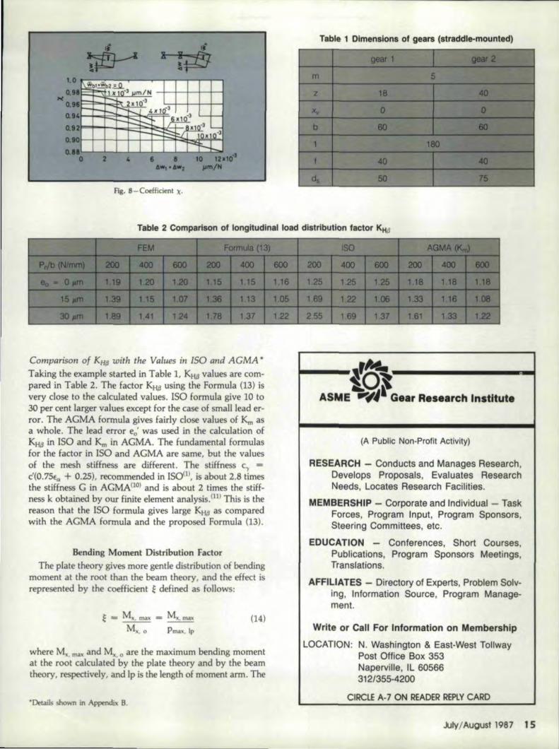
Coefficient X is shown in Fig. 8. Consequently, when theequivalent effective lead error eeq is estimated by Equations(11) and (12), the longitudinal load distribution factor KH,Bis evaluated by the fol1owing formula:
Equation (13) was tested for other pairs of gears. Its erroris about six per cent, unless mountings of small rigidity orextreme asymmetryare used.
l' 4 Gear Technology
Fig. 7a &; '7b - Examples of Iongitud inal load distribution factor For straddle-mounted (Il:'Itl and overhang-mounted gears (right).
rI
~"~-4-+~~+=~~~~~~N~~~~~~~~~~~~
o a 4 I • '0 1a.'0"6., oAWZ JIffI/N
Fla. 8-Coefficienl )1.
T:able' 2 ,Comparison, of IlongitucUnal load dltrlbutlon'actor KHP
Comparison of KHI~with ,the Vafues in ISO and AGMA *
Taking the example started in Table 1, KH,Bvalues are com-pared in Table 2. The factor KHjl using the Formula (13) isvery dose to, the calculated values. ISO formula give 10 to30 per cent larger values except for the case of small lead er-ror. The AGMA formula gives fairly close values of KI11 asa whole. The lead error eo' was used in the calculation ofKHjl in ISO and Km in AGMA. The fundamental formulasfor the factor in ISO and kGMA are same, but the valuesof the meshstiHness are different. The stiffness ,c., ""c'(O,75E" + 0.25), recommended in 150m, is about 2.8 timesthe stiffness G in kGMA(]O} and is about 2 times the stiff-ness k obtained by Our finite element analysis.nt) This is thereason that 'the ISO formula gives large KH,s as comparedwith the AGMA formula and the proposed Formula (13).
Bending Moment Distribution FactorThe plate 'theory gives more gentle distribution of bending
moment at the root 'than the beam theory, and the 'effect isrepresented by 'the coefficient ~ defined as follows:
,E=M~. mn = M~.IIW<M. It. 0 Pmax. Ip
(14)
where M~. m~" and Mx. 0 are the maximum bending momentat. the root calculated by the plate theory and by the beamtheory. respectively, and Ip is the length of moment arm. The
"Details shown in Appendix 8.
r~l()~~,----------~ASMIE ''''JIIG •• r Re. rch Ilnlntute
,(A Publlic Non-Profit Activity)
IRESEAIRCHI - Conducts and Manages Research,Develops IProposals, IEvaluates ResearchNeeds, tccatee Research FaciHties.
MEMBERSHIP - Corporat,e and Ilndividual - TaskForces, Program Input, Program Sponsors,Steeringl Committees, 'etc.
EDUCATIION- Conferences, Short Courses,Publications, Program Sponsors Meetings,TiranslaUons.
AlFFILilATIES - IDiIrectoryof IEx,pens, Problem seiv-ingl, Information Source, Program Manage-ment.
Write er 'Calli For Iln,foll'mationl 'on Membershiip
LOCATION: NI.,Washington & East-West lollwayPost Office 60x: 353Naperville, III 605663,12/355-42,0,0
OIRCLE A-7 ON READER REPllll' CARD
...lrl¥/August 1987 15
bending moment distribution factor KM~ is defined asfollows:
Mx, max
M, mean
Mx. max
Po/b) lp(15)
If the loading position and the root location adopted inthis article and in ISO are same, KM~ in our definition maybe equal to KF~ in the formula of ISO. * * From Equations(14) and (15), KMt3 is derived as follows:
(IS')
For standard gears zl :z2 = 18: 18 engaged at the highestpoint of single tooth contact of gear I, the calculated coeffi-cient ~ of gear 1,~o = [~]z1:z2=18:18, is shown in Fig. 9.Using this result, the coefficient ~ of any gears can be ap-proximately estimated by the following equation:
~ = 1.00 - (1.00 - ~o) Xp/m1.59
(16)
The value 1.59 indicates Xp/m of the gear 1 mentionedabove. The value of ~.obtained by Equation (16) is valid toestimate the bending moment distribution factor KM~ ofboth straddle- and overhang-mounted gears without anycrowning.
Total Stiffness. of Gears with Effedive Lead ErrorWhen a pair of gears with effective lead error is in mesh,
the maximum deflection at the meshing position is larger thanthe deflection of the same gears without lead error.
The total stiffness, which is defined in this article as theratio of the transmitted load and the maximum deflection,decreases with the increase of the effective lead error or KH,B.as shown in Fig.. 10. In these cases, the relative approachestimated from Lundberg's formula is included and the deflec-tion of shafts is neglected. In the case of KH(:l = 1, the stiff-ness is about six to twelve per cent larger than the stiffnesswhich is estimated by two-dimensional FEM..(11) The em-pirical formula is obtained from Fig. 10 as follows;
k = (P n/b)/[Wl + W2 + wPlmax
k = KH~-o.96[kJKH~=1 (17)
Optima~ Amount of CrowningTo minimize the longitudinal load distribution factor of
a pair of gears with effective lead error e.w this sectiondetermines the optimal amount of arc-shaped crowning. Thecenter of the curvature of the crowning is assumed to lie be-tween the side edges of the tooth.
Referring to Fig. 11, the total spacing between tooth sur-
··KF~is the longitudinal load distribution factor for bending stress in ISOllland accounts For the effect of load distribution across the face width on thebending stress at the tooth root. It is given by the following equation,
KF = KtfN = (b/h)2
l+b/h+(b/h)'
blh = ratio of face width to tooth height. the minimum of b,/h, or ~/h2
16 Gear Technology
Fig. 9 - Coefficient Eo for the calculation of KM~'
m = 5b;; 45-120
z
Fig. 10 - Total stiffness of a pair of spur gears with effective lead error.
[If1,...- b1 ----:--"'1.-
I~. I. . -.. E'eq
f2·1~. .. Y($!toddle-mQunt~d)
y (Qv~rhong - mounted)
fig. 11- Spacing between tooth surfaces caused by the effective lead error(left) and the crowning (right).
faces due to the lead frrorand the crowning is expressed inthe following form;
where 'fj = y Em" straddle-mounted gearsTJ= y - 1 for overhang-mounted gears,
When both tooth surfaces just come into contact at 'I =11 ", the position TJ" is obtained from
dSohl} =0
d1j' 'I=11:*as follows:
11*' = .... (19)
The spacing s(1I) is therefore obtained by subtracting theminimum .of 50 from 50('1) and represented in the fonowingexpression.
5(11) '=so{l1) - So min
=- 50(71) - so('I)~)
(18)
To locate the maximum load intensity at the required posi-H.onl'/'= 71 ", the shapes of crowning of both pinion and gear,(eh Cl) and ('e.2'(2), should satisfy the following equation,which is derived from Equation (19).
And to minimize the longltudinal Ioad distribution factorfor the given value of 1/10, the coefficient of '12 in Ithe Equa-tion (20.), namely,
(22)
has to be minimized,For example, the longi.tudinalload distribution of the pair
of gears studied in Table 1 is shown. in Fig. 12. In thtscakula-tion, only pinion is given the arc-shaped crowning listed in.Table 3..The solid curves 1,2,3 and 41in Fig. 12 show theload distribution of the gears with the optima] amount ofcrowning. The maximum load Pmax is reduced about 40 percent as compared with Pmax of the gears without crowning.On the other hand, the load distribution of the gears withthe larger value ofel/ct is not so reduced. Note the brokencurves in Fig. 12.
Although the method. above determines the optimalamountof crowning, it requires n". and it is not easy to deter-mine 11'" to minimize the longitudinal load distribution fac-tor. Another simple method is needed to estimate the optimal
THB FALL TECHNICAL MBBTlNGOctobtil'6·'.I".7
Top engineers trom the world's leading geartngcenters present the late.stin two intense days ofplenarY sessions. The FTM is an opportunity to
share ideas with these experts on a wide varietyof gear subjects. The meeting fonnat encouragesan active exchangeol1deas. with plenty of time
for questions. end attention to vour 1nd1v1dualtechnical Interests. Sessions w1llbe devoted 10:
GeometryBevelGear1ng
Rating and LoadsNew Inspection Techniques.
Wear and MaterialsNew Manu1acturlng Processes
'GBU. 'BDO 187Octol:) . r4~6,1.8:7
The largest show ever eoncetved entirely forthe geor industry. Browse, through the 100+ boothsdesigned to provide you maxtmurn in1onnation Inrnin1mum ttme. The wide' range ot suppliers andmanutacturers Invites you to make comparisons
right on the show floor. Vou and the exhibitors areall there for the same reason -to increase youroompetitive edge in today's tough market. See
Fig. 12 -longitudinal load distribution of the gears with the arc-shapedcrowning in Table 3.
2.5,\----t----I
s2.0+---~------l
Fig. 13-Longitudinalload distribution factor of straddle-mounted gears with the arc-shaped crowning (m = S, Zl:Zl ~ 18:40, b =b,-~ bl = 66, 1 = 180', f, ~. fl = 40, d., = 50', ck = 75, e. ~ 20J.(m).
I
e" =0'
0.5 .til 1.0../..,
amount of crowning without 11".Fig. 13 and Fig. 14 showsome results of KH.B' where only pinion is crowned withvarious amount of crowning el' From these results, the rela-tion between the optimal amount of crowning and theequivalent lead 'error eeqis obtained as follows:
2.51-----t-----j
2.01----~------l
I
0.5 JA 1.0.,1..1.01-1
--~---'o 0.5 .,1" 1.0
Fig. ]4- LOngitudinal load distribution factor of overhang-mounted gears with the arc-shaped crowning (m ~ 5, Z",Zl .. 18:40', b =b, - ~ ~ .00, 1 - 60, f] = fz = 3(), d;] = 60. d.z = 90, c]'bj = 0.5, e.·20J.(m).
18 Gear Teohnology
(23)
If the position of the center of crowning is given, the op-timal amount of crowning el opt can be found from Equa-tion (23),
When the equivalent effective lead error eeqis adopted in-stead of the error eo', .ISO recommendation for the crown-ing, or db = 0.5 and e/eeq = 0.5, is reasonable to minimizeKH.B approximately c/b = 0.5.
Some results of KIi.BandE of both straddle- and overhang-
1.O......---.----t--- __r----...,
0.1 0.2 0 3 0.4.. /b "m/mm
Fig.. lSa - Kl-f8of 'the gears with the optimal crowning.
1.0 r:-,--'"'T---""'I""------.b/m=12
o 0' 01'0
0.951----0
-1-'-..,:;.:<>-:-.,-110-. • r-..-a-.,--t----I
a ~ 0
...., '....oc ...
1.1t
1 5 ~IO
Fig. ISh - f of the gears with the optimal crowning.
mounted gears with the optimal amount 'Of crowning are plot-ted in Fig. 15. The pail' of gears used in these calculationsis m = 5, ZI:Z2 = 18:40. The bending moment distributionat the root of gears with the optimal crowning is nearlyuniform. (See Fig. 15)
ConclusionLongitudinal load distribution and bending moment
distribution at the root are calculated for the straddle- andthe overhang-mounted spur gears.
The longitudinal load distribution factor KHJj' the bendingmoment distribution factor KM,B and the total stiffness K aregiven in the illustrations. A formula for the estimation ofKHPis proposed ..The formula is very useful to estimate KHi3of spur gears whose dfective lead 'error can be 'evaluated.When KHtl is compared with the values calculated by ISO.and AGMA formulas, the load distribution factor Km ob-tained by AGMA formula is fairly dose to KHP in ourcalculation,
A method is proposed to determine the optimal amountof arc-shaped crowning of spur gears with the effective leaderror. The ISO recommendation for the determining 'Of op-timal. crowning is reasonable, and it approximately minimizesthe longitudinal load distribution factor.
Longitudinal Load Distribution . •.(Continued from page 19)
a4, = - ~(l+f+y·)JPn + a26
a5= - KS{1+f+y')lPn - KS(f+Y')lPn - 6t -oR2 6 1
a, = KS(1+f+Y')12Pn + 'Ot6
(A.3)
(2) Torsional deflection
wt = [Js(1+.f) + J(y -1- f) lpnr~
(1+f ~ y '" 1+f+y')
Wt = [Js(1 +f) + Jy'jPnr2- g
(l+f+y' ~ y ~ l+f+b)
where K =~, K S= 64 J = 32 Is = 32, ~Ed6 'irEd( TGd6' 1ICdf
(A.4)
do : pitch diameter [mm]E : modulus of elasticity = 2.06x10⁵ N I mm2
G : modulus of rigidity = 7.92xl04 N/mm2o : displacement of bearing !mm]
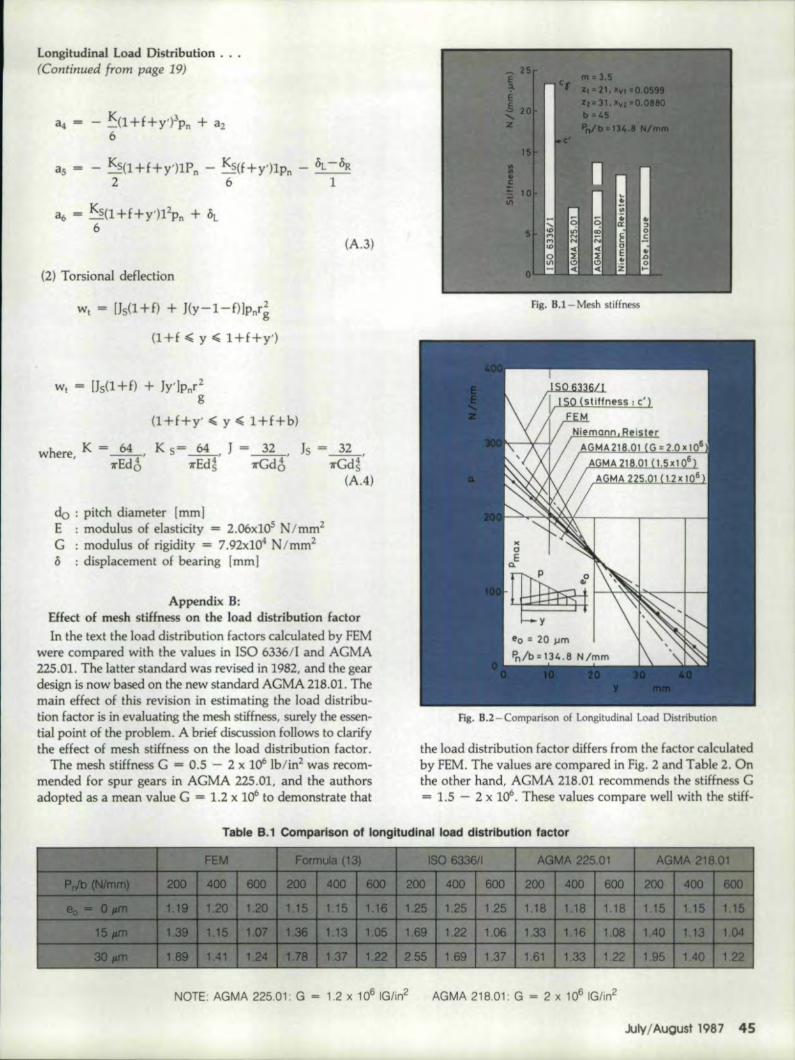
Appendix B:Effect of mesh stiffness on 'the load distribution factorIn the text the load distribution factors calculated by FEM
were compared w:ith the values in ISO 6336!l and AGMA225.01. The latter standard wasrevised in 1982, and the geardesign is now based on the new standard AGMA 218.01. Themain effect OE this revision in estimating the load distribu-tion factor is in evaluating the mesh stiffness, surely the essen-tial point of the problem. A brief discussion follows to clarifythe effect of mesh stiffness on the load distribution factor.
The mesh stiffness G = 0.5 - 2 x l061b/in2 was recom-mended for spur gears in AGMA 225.01, and the authorsadopted as a mean value G = 1.2 X 10⁶ to demonstrate that
Fig. B.1I- Mesh stiffness
Fig. 11.2- Comparison of Longitudinal Load Distribution
the load distribution factor differs from the factor calculatedby FEM. The values are compared in Fig. 2 and Table 2. Onthe other hand, AGMA 218.01 recommends the stiffness G= 1.5 - 2 x 10⁶, These values compare well with the stiff-
Ta'ble B.1 Comparison of longitudinall 10addistribuUon factor
NOTE: AGMA 225.01: G =1.2 x 10⁶ IGJin2 AGMA 218,01: G - 2 x 10⁶ IG/ln2
July/August 1987 45
ness obtained by Niemann and Reister's experiment as shawnin Fig, 8,1. They are also dose to the stiffness calculated byFEM,
In ISO 6336/1, the mesh stiffness S' the mean value of thetotal stiffness, is used to estimate the load distribution Iac-tor. Because of its definition, c1 may be used taestimate adynamic load, but it is nat logical far theestimation of theload distribution, The single stiffness c', which is approxi-mately equal to. the stiffness of atooth pair in the phase ofsingle pair contact, should be used instead, because the loaddistribution factor KHi3is used to. evaluatea contact stressat the operating pitch point. Furthermore. the root stress iscalculated for the worst loading condition (Iaading at thehighest point of single tooth contact), and the formula usesthe factor KF,s, which is related to KH(:i" The stiffness c' isquite close to the stiffness calcuated by FEM as shown inFig. A.l.
The load distributions obtained from these stiffnesses areillustrated in Fig. A. 2, which corresponds to Fig .. 2a in thetext. The load distribution obtained by AGMA 218.01 is fair-ly close to. the result calculated by FEM. If the latter isregarded as accurate, the stiffness G = 1.85 X 10" is recom-mended in this case. Using c' makes the load distribution ofISO very close to the result by FEM. The comparison of theload distribution factors is summarized in Table B.1, whichcorresponds to Table 2.
ReJer,ences,1. First draft proposal ISO/DP 6336. Part I. ISO/TC 6O(WG6-2)
386E.2. HAYASHI, K.. "Load Distribution on the Contact line of
3. CONRY, T.F. and SEIREG, A.,"A Mathematical Programm-LngTechnique for the Evaluation of toad Distribution and Op-timal Modifications for Gear Systems," Trans, ASME, Ser. B,Vol. 95, 1973, pp. 1115-1122,
4, NIEMANN, G. and REISTER, D" "Einseitiges Breitentragenbei Geradverzahnten Srimradern Messung, Berechnung undVerringerung del' Ungleichformigkeit der Lastverteilung,"Konstruktion, Vol. 18, 1966, pp. 95-106.
5. TOBE,T. and INOUE, K" "LongitudinalLoad Distribution Pac-tors of Spur Gear Teeth," Unabridged Text of Lectures of WorldCongress on Gearing, VoL 1, Paris, 1977, pp .. 211-225.
6. TOBE,T. and INOUE, K., "longitudinal Load Distribution Fac-tor of Spur Gears Considering the Effect of Shaft Stiffness."P!oceedirrr of World 5Y';Iposium ?n Gears and Gear Transmls-SIO/1S. Vol, B, Dubrovnik-Kupari, 1978. pp .. 371-381.
7. TOBE, T., KATO. M. and INOUE:. K.. "Bending of Stub Can-tilever Plate and Some Applications to Strength of Gear Teeth."Trans. ASME, Vol. 100, 1978, pp. 374-381.
11, rOBE. T., KAro, M. and INOUE, K., "True Stress and Stiff-ness of Spur Gear Tooth," Proceedings of Fifth World Con-gress on the Theory of Machines & Mechanisms, Vol. 2, Mon-treal, 1979, pp. 1165-11,
This article was presented at the Cen~ury 2 International Power Transmissions& Gearing Conference. San Francisco, CA, August, 1980. and is iwailable asASME paper 80-C2IDET-4S.