56
© BRE Global Ltd 2012 CoP 0001 Issue 1.0 Code of Practice for visual alarm devices used for fire warning Loss Prevention Code of Practice
© BRE Global Ltd 2012
CoP 0001 Issue 1.0 Code of Practice for visual alarm devices used for fire warning
Loss Prevention Code of Practice

1
This publication was jointly prepared by the LPCB with the Fire Industry Association (FIA).
This Loss Prevention Code of Practice is the joint property of BRE Global Ltd and the FIA, and is made publicly available for information purposes only. BRE Global Ltd and the FIA accept no responsibility for any non-authorised use or distribution by others of this Loss Prevention Code of Practice and may take legal action to prevent such non-authorised use or distribution

0
CONTENTS PAGE
- FOREWORD …………………………………………………….………………………….. 1 - INTRODUCTION …………………………………………………….……….…………….. 1 1 SCOPE …………………………………………………….………………..………………. 3 2 DEFINITIONS AND ABBREVIATIONS………………………….……………………….. 3 3 GUIDANCE …………………………….………………………….………………………… 4 3.1 NEED FOR VISUAL ALARM DEVICES …………………………………………………. 4 3.2 EXCHANGE OF INFORMATION AND DEFINITION OF RESPONSIBILITIES ……... 4 4 DESIGN CONSIDERATIONS …………………………………………………………….. 5 4.1 SYSTEM COMPONENTS …………………………………………………………………. 5 4.2 VISUAL ALARM DEVICES IN EXPLOSIVE GAS OR DUST ATMOSPHERES …….. 5 4.3 MONITORING, INTEGRITY & RELIABILITY OF VAD CIRCUITS TO CIE ………….. 6 4.4 ALARM ZONES …………………………………………………………………………….. 7 4.5 VISUAL ALARM SIGNALS ………………………………………………………………... 8 4.6 SELECTION, SPACING AND SITING OF VADS ………………………………………. 11 4.7 POWER SUPPLIES ………………………..………………………………………………. 19 4.8 CABLES, WIRING AND OTHER INTERCONNECTIONS …………………………….. 20 4.9 RADIO-LINKED SYSTEMS ……………………………………………………………….. 20 4.10 ELECTROMAGNETIC COMPATIBILITY ………………………………………………... 21 4.11 ELECTRICAL SAFETY ……………………………………………………………………. 22 5 INSTALLATION …………………………………………………………………………….. 22 5.1 RESPONSIBILITY OF INSTALLER …………………………………………………........ 22 5.2 INSTALLATION PRACTICES AND WORKMANSHIP …………………………………. 23 5.3 INSPECTION AND TESTING OR WIRING ………………………………..………........ 23 6 COMMISSIONING ………………………………………………….……….……………... 23 6.1 COMMISSIONING PROCEDURES ……………………………………………………… 23 6.2 DOCUMENTATION ……………………….……………………………………………….. 24 6.3 CERTIFICATION, ACCEPTANCE AND VERIFICATION ……………………………… 24 7 MAINTENANCE …………………………………………………………………………….. 24 7.1 ROUTINE TESTING ……………………………………………………………………….. 24 7.2 INSPECTION AND SERVICING ………………………………………………………….. 24 7.3 NON-ROUTINE ATTENTION ……………………………………………………………... 24 7.4 MODIFICATIONS TO THE SYSTEM …………………………………………………….. 25 8 USER RESPONSIBILITIES ……………………………………………………………….. 25 9 PUBLICATIONS REFERRED TO: ……………………………………………………….. 26 ANNEX A LOOK UP TABLES FOR VADS SITING ……………………………………….….… 27 ANNEX B TYPICAL AMBIENT ILLUMINATION LEVELS IN BUILDINGS…..……………..…. 45 ANNEX C EXAMPLES OF VAD SITING IN TYPICAL SITUATIONS………………………….. 47

1
FOREWORD This Code of Practice provides recommendations for the planning, design, installation, commissioning and maintenance of visual alarm devices (VADs) in and around buildings, other than single-family dwellings. The Code of Practice does not recommend whether or not VADs should be installed in any given premises, nor the areas in which they should be provided, although some guidance is given.
INTRODUCTION
The primary means of giving warning of fire in a building comprises an audible alarm signal (from a bell or electronic sounder) or a verbal message (from a voice alarm system). However, in many buildings, the audible message needs to be supplemented by a visual alarm signal controlled by a fire detection and alarm system that should normally comply with BS 5839-1. There are a number of situations in which visual alarm signals are appropriate, such as:
• as a means of giving warning to deaf and hard of hearing people; • in areas of high ambient noise level; • in buildings in which the initial warning of fire may be restricted to staff (e.g.
certain public assembly buildings); • in broadcasting studios, in which an audible alarm would cause interruption to live
broadcasts; • hospital operating theatres where an audible alarm may be disruptive or interrupt
operating procedures; • stage 1 visual alarm in gaseous extinguishing systems as recommended by BS
7273-1. In certain applications, VADs may be required in new buildings and extensions to existing buildings under the provision of legislation. For example, building regulations require that buildings are safely accessible for disabled people, including means of evacuation for those who are deaf or hard of hearing. This may necessitate the provision of VADs in certain buildings or parts of buildings. For example, in England and Wales, Part M of Schedule 1 to the Building Regulations 2000 (as amended) requires that reasonable provision shall be made for people to gain access to and use a building and its facilities. For compliance with this Regulation BIP 2065:2004 provides guidance in support of Part M which recommends that any fire alarm within sanitary accommodation consists of both a visual and audible signal. BIP 2065:2004 also advises that sleeping accommodation in buildings where such accommodation is provided for a significant number of people (e.g. hotels, motels and student accommodation) will satisfy the requirements of Part M if, amongst other things, all bedrooms have a visual fire alarm signal in addition to any audible signal required under Part B of the Building Regulations (which addresses fire safety). In the case of existing buildings, in England and Wales, the Regulatory Reform (Fire Safety) Order 2005 (and equivalent legislation in Scotland and Northern Ireland) requires that, where necessary in order to safeguard the safety of relevant persons, premises are equipped, to the extent that is appropriate, with suitable fire detection and fire alarm systems. Relevant persons, in the context of the Order, include all persons who are lawfully on the premises (including, therefore, deaf and hard of hearing people). Similarly, the Disability Discrimination Act 1995 (as amended) requires that reasonable adjustments be made to facilitate the use of buildings by disabled people. The
2
requirements of the Disability Discrimination Act may necessitate the provision of VADs in buildings to provide warning of fire for deaf and hard of hearing people. BS 5839-1 provides recommendations for the design, installation, commissioning and maintenance of fire detection and fire alarm systems for buildings. Specifically, it makes recommendations in respect of the following:
• adequacy in number and distribution of VADs, which should be readily visible from all normally accessible locations, throughout the area in which they are provided, under normal ambient lighting levels;
• the rate at which VADs should flash; • the height at which VADs should be mounted; • the differentiation of the visual signal from any other visual signal used in the
premises; • the intensity of output, which should be sufficient to attract attention, but not so
high as to cause difficulty with vision due to glare. The purpose of this Loss Prevention Code of Practice is to supplement the guidance given in BS 5839-1 with respect to design, installation, commissioning and maintenance of VADs. BS 8300 provides guidance on good practice in the design of domestic and non-domestic buildings and their approaches so that they are convenient to use by disabled people. It recommends that, for non-domestic buildings, in areas where people are likely to be on their own (e.g. toilets, bathrooms and isolated offices), alarm/alerting systems for people with impaired hearing, such as flashing beacons and vibrating devices, should be installed in conjunction with proprietary or conventional fire alarm systems. BS EN 54-23 specifies the requirements, test methods and performance criteria for VADs in fire detection and fire alarm systems. The performance of VADs is assessed against a minimum required illumination of 0.4 lux on surfaces perpendicular to the direction of the light emitted from the device. The measured light intensity of the device is used to define the effective space (coverage volume) that it can cover. This minimum level is such that adequate visual warning will be given on any surfaces within the coverage volume, so that the device does not necessarily have to be directly within the field of view of the recipient to be effective. In BS EN 54-23, VADs are classified in three categories namely ceiling-mounted, wall-mounted and an open class. Each of these categories is further defined by the geometry of the coverage volume which is specified by the manufacturer. The coverage volume can thus be used to determine VAD spacing within the building. This Loss Prevention Code of Practice recommends the use of VADs complying with BS EN 54-23. It recommends the application of some multiplication factors for the coverage volume to account for the expected ambient light levels and the need to depend on direct or indirect viewing of the VAD.

3
1 SCOPE
This Code of Practice gives recommendations for the planning, design, installation, commissioning and maintenance of facilities using VADs to give the primary warning of fire to certain persons in and around buildings, other than single-family dwellings. This Code of Practice does not recommend whether or not VADs should be installed in any given premises, nor the areas in which they should be provided. NOTE For the purpose of this Code of Practice it is assumed that a decision has already been taken to provide VADs. This Code of Practice is intended to be used for VADs complying with BS EN 54-23. This Code of Practice does not apply to: 1) visual indicators installed in or around premises to give those responding to a
fire alarm signal (e.g. the fire and rescue service) an indication of the location of the fire (e.g. visual indicators located outside units in a shopping mall or visual indicators used to reduce the search distance (as defined in BS 5839-1));
2) situations in which the fire strategy for the building does not necessitate the
provision of VADs as the primary means of giving a warning of fire to any persons;
3) visual indicators used to indicate system or device status, e.g. on CIE or
detectors.
2 DEFINITIONS AND ABBREVIATIONS For the purposes of this document, the terms and definitions given in BS 5839-1 and BS EN 54-23 and the following apply. ambient light level the light level normally present in an area of a building NOTE In this Code of Practice, in designing a VAD installation, account is taken of the ambient light level, which is likely to vary (e.g. over the course of a day). CIE control and indicating equipment combined VAD a VAD combined with another device of a fire detection and fire alarm system EXAMPLE: Combined VAD and alarm sounder or VAD and smoke detector. deaf person a person who cannot hear sounds less than 80 dBA hard of hearing person a person who can only hear sounds above 25 dBA but can hear sounds less than 80 dBA NOTE The above two definitions are based on information published by the Royal National Institute for Deaf people (RNID) and the Royal Association for Deaf people (RAD).

4
photosensitive epilepsy recurrent convulsions precipitated by visual stimuli, particularly flickering light 3 GUIDANCE 3.1 NEED FOR VISUAL ALARM DEVICES The need for VADs in any specific building will normally be determined by the authority responsible for enforcing fire safety legislation in that building and/or by a fire risk assessment carried out by the person on whom legislation imposes a duty to do so.
NOTE A VAD within a bedroom is not expected to wake a sleeping person. In general, it is appropriate to install VADs in any buildings that are likely to be occupied by a significant number of deaf or hard of hearing people, in areas of buildings with high ambient noise levels, in bedrooms of non-domestic accommodation in which people sleep and in a number of specialized circumstances, such as those described in the Introduction to this Code of Practice. The main criterion for installation of VADs is their ability to give a warning of fire in situations in which audible fire alarm devices cannot reliably do so or are inappropriate. Where there is uncertainty regarding the need for VADs, reference should be made, by the developer, potential purchaser or user to one or more of the following: • The relevant part of BS 9999; • Guidance documents that support fire safety legislation; • Disabled access legislation and associated standards, such as BS 8300; • Any authority responsible for enforcing fire safety legislation that applies to the
premises; • Any relevant fire risk assessment. The purchaser or user should ensure that the designer of a fire detection and alarm system is adequately apprised of the need for VADs and any relevant requirements in respect of such devices imposed by enforcing authorities. 3.2 EXCHANGE OF INFORMATION AND DEFINITION OF RESPONSIBILITIES VADs are used to supplement, in specific circumstances, other alarm devices. As such, in providing an effective means of alerting and evacuating occupants of the building, they form part of its fire safety strategy. Therefore, it is particularly important that the use of VADs is based on an agreed building evacuation plan.
In order to ensure that adequate provision is made for the use of VADs, it is advisable that, where relevant, there be consultation between the user or purchaser and the system designer. In some cases, there will also be a need for consultation between the user or purchaser, the system designer and the enforcing authority.
The following recommendations apply:

5
1) Generally, the recommendations in BS 5839-1 for exchange of information and definition of responsibilities should be followed;
2) The requirements for VADs, in particular those relating to their location and illumination output, should be ascertained as accurately as possible by consultation between the user or purchaser and other interested parties, such as the enforcing authority;
3) If a building contains alarm systems associated with hazards other than fire, the use of different signals (e.g. different colour and flash rate) and their priorities should be agreed by all interested parties; NOTE Although, in general, fire will have the highest priority, there are buildings in which other hazards may have higher priorities than fire.
4) The user or purchaser of the system (or an appointed representative) should ensure that, to the extent appropriate, consultations with the authority responsible for enforcing fire safety legislation (e.g. the building control body, fire and rescue authority, Health and Safety Executive) on the requirement for VADs take place at, or prior to, the system design stage;
5) The designer of the system should ensure that, to the extent appropriate, consultations on the requirements for VADs take place at the design stage between all relevant interested parties, including the user or purchaser, architects and, where necessary, fire engineering consultants.
4 DESIGN CONSIDERATIONS 4.1 SYSTEM COMPONENTS 4.1.1 CONFORMANCE TO EN STANDARDS VADs should conform to the requirements of BS EN 54-23. Radio linked devices should also conform to the requirements of BS EN 54-25. Devices which incorporate isolators should conform to BS EN 54-17. 4.1.2 COMBINED VADs Combined VADs should conform to the relevant BS EN standard for each element of the device. Combined VADs can comprise a number of additional and different functions, such as an alarm sounder and/or fire detector. Where such combined units are provided all elements should comply with the relevant standards when combined together. Such combined units should have documentation to qualify any changes to performance in their combined configuration. NOTE For example, it is likely that when a sounder and beacon are combined, the light dispersion from the VAD and the polar dispersion from the alarm sounder will be affected by the proximity of the other device. 4.1.3 CIE CIE should conform to BS EN 54-2. 4.1.4 POWER SUPPLY Power supply equipment should conform to BS EN 54-4. 4.2 VISUAL ALARM DEVICES IN EXPLOSIVE GAS OR DUST ATMOSPHERES 4.2.1 GENERAL

6
If it is necessary to install a VAD in areas where an explosive atmosphere could result from the presence of flammable gases, vapours or mists, or the presence of combustible dusts, special protection measures are essential to ensure that the potential for ignition of the atmosphere by the VAD or the wiring to the VAD is minimized.
BS EN 60079-0 gives general requirements for electrical apparatus for use in potentially explosive gas atmospheres.
BS EN 61241-0 gives general requirements for electrical apparatus for use in potentially explosive dust atmospheres.
4.2.2 EXPLOSIVE GAS ATMOSPHERES Intrinsically safe circuits of VADs should conform to BS EN 60079-25.
Any systems (or part of a system) protecting an area, or with cables passing through an area, in which there may be an explosive gas, vapour or mist atmosphere should conform to BS EN 60079-14 with regard to design, selection and installation of equipment.
4.2.3 EXPLOSIVE DUST ATMOSPHERES Any systems (or part of a system) protecting an area, or with cables passing through an area, in which there may be an explosive dust atmosphere should conform to BS EN 61241-14 with regard to selection and installation of equipment and BS EN 61241-17 with regard to inspection and maintenance. 4.3 MONITORING, INTEGRITY AND RELIABILITY OF VAD CIRCUITS TO
CONTROL EQUIPMENT 4.3.1 GENERAL Visual alarm circuits are external to control equipment. The VADs are generally used in addition or as an alternative to sounders to indicate the need for evacuation of the building. Therefore monitoring, integrity and reliability should be equal to that of sounders. Reference should be made to BS 5839-1 Clause 12. 4.3.2 FAULT MONITORING a) A fault indication should be given at the CIE within 100 s of the occurrence of
any of the following conditions:
1) short circuit or open circuit of any circuits serving VADs;
2) removal from its circuit of a VAD that is designed to be detachable from a base.
b) Visual indications of the faults specified in a) 1) should continue to be given at the CIE during a fire alarm condition.
4.3.3 SYSTEM INTEGRITY a) A fault on one circuit containing VADs, should not affect any other circuit; b) Any fault forming a cross-connection between a visual alarm circuit and another
circuit should not affect any circuits other than the two circuits involved; c) It is recommended that in the event of a single open circuit or short circuit fault
on any circuit that serves a VAD, at least one single fire alarm sounder normally located in the vicinity of the CIE should still sound in the event of a fire alarm condition (see BS 5839-1). Where deaf or hard of hearing persons may be
7
required to respond to this alarm condition the alarm sounder in this instance should be supplemented by a VAD;
NOTE It is possible to comply with the above recommendation by at least the following two arrangements: • wiring all VADs within the building on a single circuit, with the additional provision of
a second, independent circuit, to which only a single VAD, located in the vicinity of the CIE, is connected;
• wiring all VADs on a ring circuit capable of transmitting signals in either direction; the
first (or last) three devices on the circuit would then comprise a short circuit isolator, capable of isolating the circuit in the event of detection of a short circuit, a VAD and a further short circuit isolator.
d) Where two (or more) VAD circuits are necessary in order to satisfy the
recommendations of c) the circuits should not be contained within a common cable sheath. For example, two circuits intended to satisfy these recommendations should not be served by a common four core cable, as this would not adequately protect against the simultaneous loss of both circuits;
e) Where a VAD is combined with a fire detector, disablement of the detector
should not affect the ability of any VAD to respond to an alarm signal; f) if a VAD is combined in the base of a fire detector, removal or disablement of
the detector should not affect the ability of the VAD to respond to an alarm signal;
g) If facilities are incorporated to provide synchronisation or to control the functions
of non addressable VADs, precautions need to be taken to ensure that such facilities are not affected by other devices which may be connected to the VAD circuit and conversely that such facilities do not affect the satisfactory operation of other devices sharing the circuit.
4.4 ALARM ZONES 4.4.1 GENERAL In many buildings, the evacuation strategy will be very simple; on operation of any manual call point, or detection of fire by an automatic fire detector, fire alarm devices will operate throughout the building to indicate the need for evacuation of the entire building. In larger, more complex buildings, the “Evacuate” signal may, in the first instance, be restricted in extent (e.g. to a single floor, a limited number of floors or a limited area of the building). In order to support such arrangements, it is necessary for the building to be divided into a number of individual alarm zones, such that the operating state of fire alarm devices in any alarm zone is independent of the operating state of fire alarm devices in all other alarm zones. The fire alarm devices in the building are thus grouped, so that, at any point in time, all VADs within any given alarm zone are in the same state, i.e. quiescent or flashing. The need for sub-division of a building into discrete alarm zones may arise for a number of reasons, including:

8
• the use of phased evacuation; • to avoid unnecessary disruption when false alarms occur; • to provide a visual alarm signal in specific areas, e.g. indication of first
detector operation in a gaseous extinguishing system (see BS 7273-1). 4.4.2 OVERLAP SIGNALS The extent of any overlap of signals from VADs between alarm zones should not be sufficient to result in confusion of occupants in any area of the building. 4.4.3 COMMON VISUAL SIGNAL A common visual signal should be used throughout all alarm zones to convey the need for evacuation. 4.5 VISUAL ALARM SIGNALS 4.5.1 COLOUR AND FLASH RATE The VAD should emit a white or red light flash as required in BS EN 54-23. In addition, for the first stage of a multi-stage alarm system, the colour amber may be used (see Clause 4.5.4). Generally, white flashing light is more effective in alerting individuals as it includes a broader spectrum of colours. The flash rate should be between 0.5 Hz and 2 Hz. Care should be taken when using red flashing light since it is more likely to induce a seizure in some individuals (see Clause 4.5.5). 4.5.2 FIRE ALARM WARNINGS FOR DEAF AND HARD OF HEARING PEOPLE Deaf and hard of hearing people can be present in all parts of a building; it is important therefore that all areas are considered when planning for the provision of VADs. The most important areas for the provision of VADs are those where it is possible for a person to be alone or isolated from others with normal hearing. In public areas, deaf and hard of hearing people are likely to receive assistance from the other people present. However, in all areas, the provision of VADs should be adequate for the needs of deaf and hard of hearing people. VADs should typically be installed in: • bedrooms; NOTE These devices are not intended to wake sleeping people; there are more effective methods, such as vibrating devices. • sanitary accommodation; • certain areas where people are likely to be on their own. In all other areas in which VADs are necessary, the output of at least one VAD should be visible from any point, either directly or indirectly. 4.5.3 FIRE ALARM WARNINGS IN AREAS OF HIGH AMBIENT NOISE Where high ambient noise might be present for periods of time, it might not be practicable for fire alarm sounders to achieve sound levels greater than the 5 dB above ambient noise level recommended by BS 5839-1 to ensure audibility. Also, where the ambient noise level is likely to exceed 85 dBA, personnel are normally required to use ear defenders. Areas of high ambient noise are likely to be well defined within a building owing to health and safety audits, thereby clearly identifying the need for VADs. In areas where the ambient noise level is likely to exceed 85 dBA, VADs should be provided to

9
supplement the audible fire alarm signal. The VADs should be distributed so as to be readily visible, under the normal ambient light conditions, from all normally accessible locations throughout the area in which they are required. In industrial and manufacturing areas it is essential to ensure that the visual alarms are clearly distinguishable from any other visual signals used for machine or process alarms. 4.5.4 STAGED ALARMS In simple buildings of limited size, a single-stage fire alarm arrangement is normally used. In this arrangement, fire alarm sounders are either in the on or off state, while VADs are either flashing or off. On operation of any manual call point or automatic fire detector, the fire alarm sounders and VADs operate to provide a single, common evacuation signal throughout the premises immediately (i.e. there is a ‘single-phase’ evacuation). In certain large and/or high rise buildings, a staged fire alarm arrangement is commonly used. In this arrangement, the initial warning of fire is given in a restricted area or is restricted to key personnel, but can be extended in further stages to warn, ultimately, all occupants of the premises. The arrangement might apply regardless of whether the alarm is triggered by a manual call point or an automatic fire detector, or it might apply only to alarm signals triggered by automatic fire detectors. It is essential to ensure that the arrangement adopted for VADs exactly parallels the arrangement adopted in respect of fire alarm sounders, so that the appropriate signal (e.g. alert or evacuate) can be given by either form of warning device. There are various circumstances in which a staged fire alarm arrangement may be appropriate. These include, but are not restricted to, the following: • In certain large or high rise buildings; • Any buildings with phased evacuation; • In most hospitals (for which guidance is given in HTM 05-03 Part B); • To minimize disruption from false alarms; • In certain places of public entertainment; • In a large, widely spread range of low rise buildings, such as an industrial
complex. In all of the above cases, the evacuation strategy will normally require the support of a staged alarm system, which is capable of giving two or more stages of alarm within any area. In a two-stage alarm, the system may be capable of giving an ‘Alert’ signal in those areas not immediately affected, as a warning of impending evacuation, and an ‘Evacuate’ signal in those areas in which immediate evacuation is required. In this case, where VADs are used, there must be a means of unambiguously indicating each stage. This could, for example, take the form of two VADs, each of a different colour. The two stages of alarm could also be indicated by means of different flash rates. This may constitute a sufficient form of distinction in the case of premises occupied only by trained staff, who could readily distinguish between two flash rates, each of which is of a sufficiently low frequency to avoid risk to photosensitive epileptic persons. The use of different colours (provided these are red, amber or white) might be a suitable means of distinguishing between alarm stages. However, this will not be suitable for people with certain forms of colour-blindness, particularly if the two different signals are given by a single device that has the ability to produce two different colours of signal.

10
Where one of the colours used is amber, this should indicate the first of the multiple stages. Given the considerations described above, it is recommended that, where two different stages of alarm need to be given by VADs, two spatially separated VADs should be provided at each VAD location, each giving a signal of a different colour (selected from the options of red, amber or white). The distinction between the two devices may be further amplified by different flash rates, subject to compliance of each rate within the recommendations of Clause 4.5.1. Except in premises occupied only by a limited number of trained staff with normal colour vision, on, or adjacent to, each device there should be an appropriate legend, clearly legible at an appropriate distance at which the visual alarms might reasonably be anticipated to be viewed by occupants. NOTE 1 This recommendation is not intended to preclude the incorporation of the two, spatially separated devices within a single housing, provided, in this case, each ‘section’ of the single housing is appropriately identified by a suitably located legend. NOTE 2 Where more than one VAD is being provided with different flash rates or colours, for selected alarm stages, consideration should be given to the overall effect to avoid the occurrence of epileptic seizures see 4.5.1.& 4.5.5. Another form of two-stage alarm is one in which the initial alarm is restricted to staff, with the subsequent stage taking the form of an ‘Evacuate’ signal throughout all or part of the premises. In a three-stage alarm the system may be capable of giving a general or localized staff alarm, an ‘Alert’ signal and an ‘Evacuate’ signal. The main purpose of a fire detection and alarm system is to support the required fire and evacuation procedures. Since various arrangements are possible, it is absolutely vital that, other than in small, simple buildings, the fire procedures and evacuation strategy are formulated before final design of visual warning arrangements. The ‘cause and effect’ logic of the system, the control facilities provided and the configuration of VADs will be governed by the procedures the system is intended to support. For example, to facilitate a staged alarm arrangement, in which ‘Alert’ and ‘Evacuate’ signals can be given by VADs, it will be necessary to divide the building into different visual alarm zones. Where a staged alarm system is proposed, there should be early consultation with all relevant enforcing authorities, which should include any arrangements utilizing VADs. It should be noted that, in certain phased evacuation buildings, no single control should cause VADs to give an ‘Evacuate’ signal throughout the building; a separate ‘Evacuate’ control should be provided for each alarm zone (see sub-clause 19.2.1b) of BS 5839-1). In some buildings, a ‘silent’ staff alarm signal may be given by VADs complying with the recommendations of this Code of Practice and Clause 17 of BS 5839-1. There should then be provision, throughout all areas of the building, to warn all occupants of the building by means of an ‘Evacuate’ signal (if appropriate, preceded by an ‘Alert’ signal), which may be given by audible alarm sounders and/or VADs. A staff alarm signal should automatically change to an ‘Evacuate’ signal in at least the relevant alarm zone, unless manual intervention to stop the associated timer occurs at control equipment. The period should be agreed with all relevant enforcing authorities, but should be sufficient to enable staff to investigate the initial alarm signal; the period should not normally exceed six minutes, but should be identical in the case of both audible and visual alarm signals. Where two different stages of alarm are intended to be distinguished, in whole or in part,
11
by different flash rates, it is essential to synchronize the VADs so that, for example, the ‘Alert’ signal cannot be confused with an ‘Evacuate’ signal of a higher flash rate. Provision may be made for a visual alert signal to cease automatically after 30 seconds, provided that, at periods not exceeding three minutes, the signal is restored for a period of at least ten seconds until manually stopped. Any such arrangement should parallel exactly the arrangement adopted for audible alarm signals. 4.5.5 PHOTOSENSITIVE EPILEPSY People with photosensitive epilepsy suffer seizures which are triggered by certain frequencies of flashing lights or contrasting light and dark patterns. Seizures are most likely to be triggered by frequencies between 3 Hz and 30 Hz, although this varies from person to person; while some people are sensitive at frequencies higher than 30 Hz, it is unlikely that seizures will be triggered by frequencies less than 3 Hz. Some people are sensitive to geometric patterns, which have strong contrasts of light and dark e.g. stripes or checks. Such contrasting patterns are more likely to be a trigger if they are moving, changing direction or flashing, rather than if they are still. For the avoidance of photosensitive epileptic seizures the following apply:
a) either:
1) the product of n x f ≤ 3 Hz, where n is the number of VADs visible from any single point and f is the flash rate of each device; or 2) the VADs should be synchronized in accordance with the requirements of Clause 4.3.7 in BS EN 54-23.
b) VADs mounted side by side to provide Alert and Evacuate signals should not operate simultaneously;
c) Care should be taken when siting VADs in areas with highly reflective surfaces (see 4.6.5). For example, even if, from a particular point, only one VAD can be viewed directly, reflections from (unsynchronised) VADs might also be visible. Under these circumstances VADs might need to be synchronised.
4.6 SELECTION, SPACING AND SITING OF VADS 4.6.1 GENERAL When designing systems incorporating VADs, a number of factors determining their effectiveness in giving warning should be considered. At the onset of the design, it is important to identify the following:
a) the illumination characteristics of the VADs used; b) any factors within the application environment that might affect the visual impact of the VAD illumination, including the following:
1) level of ambient light;
2) reflectivity of surfaces;

12
3) effect of colour;
4) required field of view;
5) usage and occupation;
6) environmental conditions.
4.6.2 METHOD OF DESIGN This Loss Prevention Code of Practice permits two alternative approaches to the design of VAD installations. The first is a "pre-determined approach", which may be used for rooms of simple geometry, specified size and frequently encountered levels of ambient illumination. In this approach, the designer may use the "look-up tables" in Annex A to determine the number and siting of VADs for the room in question. The second is an "application-specific solution", which can be used in any situation, but will be essential in more complex situations that are outside the scope of the "pre-determined approach". In this 'engineered' solution, the design should be based on the recommendations contained in sub-clauses 4.6.3 to 4.6.9. 4.6.3 VAD ILLUMINATION CHARACTERISTICS BS EN 54-23 specifies VADs in terms of the range at which a required illumination of 0.4 lux is achieved. This defines the coverage volume of VADs compliant with the European standard. NOTE 1: Reference may be made to Annex A in BS EN 54-23 for method of measurement of the effective light intensity and the calculation of coverage distance.
BS EN 54-23 defines three categories of VADs for which the coverage volume is defined as follows:
a) category “C-x-y” for ceiling-mounted VADs where:
1) x is the maximum height of either 3,6 or 9 metres at which the VAD may be mounted,
2) y is the diameter in metres of the cylindrical volume covered (to a minimum level of 0.4 lux) when the device is mounted to the ceiling;
NOTE 2 For example, C-3-12 corresponds to a ceiling-mounted device giving a coverage cylindrical volume of 12 m diameter at a height of 3 m. A ceiling-mounted device can be considered to cover a square of side y/1.4 m, and a cubic volume of xy2/2 m3. For example, a VAD complying with C-3-12, will cover a volume of 3 m x 8.5 m x 8.5 m.
b) category “W-x-y” for wall-mounted VADs where:
1) x is the maximum height of the device on the wall in metres, with a minimum value of 2.4 m,
2) y is the length and width in metres of the cubic volume covered (to a minimum level of 0.4 lux) when the device is mounted to the wall at a height of x;
NOTE 3 For example, W-2.4-6 corresponds to a wall-mounted device giving a coverage cuboid volume of 2.4 m x 6 m x 6 m when mounted at a height of 2.4 m.
c) c) category “O” for VADs the coverage volume of which is fully specified by the manufacturer, including the following information:
1) the recommended mounting position for the device,
13
2) any specific requirement for mounting the device in a particular orientation, and how this orientation can be identified on the device,
3) any restrictions on the minimum and maximum allowable mounted height,
4) the shape of the coverage volume in which the required illumination of 0.4 lux is achieved, its dimensions and how it is geometrically related to the device.
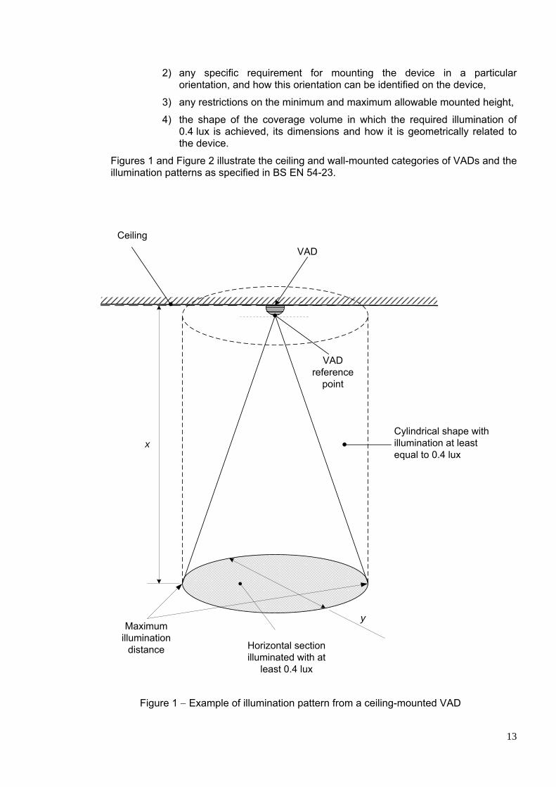
Figures 1 and Figure 2 illustrate the ceiling and wall-mounted categories of VADs and the illumination patterns as specified in BS EN 54-23.
Horizontal section illuminated with at
least 0.4 lux
x
y
Cylindrical shape with illumination at least equal to 0.4 lux
Maximum illumination
distance
Ceiling
VAD reference
point
VAD
Figure 1 − Example of illumination pattern from a ceiling-mounted VAD
14
VAD
Cuboid shape with illumination at least equal to 0.4 lux
x
y
y
Horizontal section illuminated with aleast 0.4 lux
Maximum illumination
distance
Ceiling
VAD reference
point
Figure 2 − Example of illumination pattern from a wall-mounted VAD
15
4.6.4 AMBIENT LIGHT LEVEL The ambient light level in the vicinity of a VAD will affect its visibility and, hence, its ability to give effective warning. In designing the installation, consideration should be given to the variation of the ambient light level during the periods when the VADs are intended to be effective in giving a warning of fire.
The ambient light level is determined by the extent of artificial lighting in combination with any natural lighting. A wide range of lighting levels can be found in applications where VADs are required to be used. Artificial lighting conditions vary to suit the needs of specific human activities e.g. different lighting conditions will be found in dwellings, offices, shops and places of public entertainment. The ambient light level can also be influenced by external natural light conditions such as bright sunshine, daylight, overcast sky, twilight and moonlight.
Information on the recommended illumination in workplaces and typical ambient light levels is given in Annex B.
Because of the large variations in ambient light levels which may exists in specific applications, it is important that the highest level expected should be considered when selecting VADs.
In general, the coverage volume of VADs may be increased in low ambient light levels but may need to be decreased for brightly lit spaces or in spaces that can be flooded by strong daylight, such as rooms with south-facing windows.
4.6.5 REFLECTIVE SURFACES Some surfaces may reflect or absorb light. It is important to assess and understand the types of surfaces involved as different materials will react differently to the emitted light. The reflection of light may be specular when the entire incident light is reflected in one direction from a shining surface, e.g. glass mirror, polished metal or gloss paint, or it may be diffuse when the light is reflected in a many directions from an uneven or granular surface. The reflective characteristic of most materials is such that they will exhibit both specular and diffuse reflections.
Reflective surfaces can increase the effective field of vision of the occupants in the protected area by providing multiple paths for the light to attract their attention. In assessing this, care should be taken to take into account only permanent reflective structures and the degree of specular reflection that will be given by the surfaces involved.
4.6.6 THE EFFECT OF TINTED EYE PROTECTION In some industrial environments, personnel use tinted eye protection. It should be ensured that the light output of the VADs is bright enough to overcome the attenuation provided by the eye protection. If tints are used, they will attenuate specific colours. In such circumstances, it is preferred that visual alarms should provide white light for maximum effectiveness. NOTE It is not proposed that visual alarms should overcome the very high density filters used by welders, as these are normally only used for short periods when actually welding.

16
4.6.7 FIELD OF VIEW BS EN 54-23 requires the manufacturer to declare the coverage volume (volume where the required intensity is achieved) of the VAD. Consideration should be given, however, to the presence of any obstructions, such as partitions or furniture that could affect the actual VAD coverage. At any position within a space where a VAD is required, any individual should be able to view its light directly or reflected from adjacent surfaces.
4.6.8 THE ENVIRONMENT This Code of Practice specifies VADs for two types of application environment, Type A, generally for indoor use and Type B, generally for outdoor use. For type A VADs, a minimum ingress protection of IP21C is required whilst for type B the requirement is IP33C. Type A VADs are tested for correct operation in the temperature range -10 °C to +55 °C. Type B VADs are tested for correct operation in a wider temperature of -25 °C to +70 °C. Additionally, Type B VADs are tested for higher resistance to atmospheric humidity over longer periods of time. The selection of VADs should take into consideration the nature of the environment where it is intended to be installed and a Type A or Type B VAD should be chosen accordingly.
4.6.9 SELECTION, SITING AND SPACINGS 4.6.9.1 GENERAL This clause gives general recommendations for the selection, siting and spacing of VADs. One or several VAD(s) of adequate output can be expected to serve any room or length of corridor if optimally located on perimeter walls or suspended below the ceiling so that the signal can spread throughout the space, unobstructed by furnishings, equipment, or room geometry.
Selection of VADs and their placement in unusual situations, such as large spaces with high ceilings, dark or non-reflective walls, or very high ambient lighting levels may need special consideration, possibly involving photometric calculation for system design rather than by the application of the pre-determined approach (see 4.6.2) in these guidelines.
In multipurpose facilities where movable elements may at times be deployed or in certain warehouses, libraries, convention centres and other building types where devices would not be visible when installed at specified heights, the optimal placement of VADs may require customized solutions.
Annex C gives examples of VAD siting in typical situations.
4.6.9.2 GENERAL RULES FOR SELECTION AND SITING OF VADS a) Wall-mounted VADs are likely to be effective in a wide range of applications, including
those with high ambient light levels.
b) Ceiling-mounted VADs (or VADs suspended from the ceiling) can be used as an alternative to wall mounted devices and are more practical to install in large open areas or where wall mounting is difficult.

17
c) The coverage volume of open category devices is specified by the manufacturer, the recommendations of which should be taken into consideration when determining the siting and spacing of the devices at given ambient light levels.
d) Where there is continuous surveillance in a specific direction, for example in a seated auditorium or a broadcasting studio, widespread coverage might not be necessary. In such a case, one or more VAD(s) strategically sited to be visible in the direction of surveillance might be sufficient.
e) Wherever possible, VADs should be sited such that all occupants of the room can have a clear line of sight of the device. Where, due to the specific usage of the space or fixed obstructions within it, direct line of sight cannot be achieved, the selection and siting of VADs should be such that the required level of illumination is provided on appropriate adjacent surfaces, taking into account the reflectivity of such surfaces (see Clause 4.6.5).
f) Where the effectiveness of VADs depends on indirect illumination, the surfaces on which there is dependence for visibility of the visual alarm signal should be within the volume of coverage determined from the manufacturer's data provided in accordance with the requirements of BS EN 54-23 (see Clause 4.3.6.2) unless:
• low ambient light level permits an increase in the coverage distance (see Clause 4.6.9.4); or • high ambient light level necessitates a decrease in the coverage distance (see Clauses 4.6.9.4); or • it has been determined, on the basis of risk, that the illumination requirement may be reduced or needs to be increased.
g) Where the area to be covered is larger than the coverage area of suitable devices, a sufficient number of VADs should be sited around the perimeter of the space and/or on the ceiling to ensure that the required illumination levels are satisfied.
h) Where deaf or hard of hearing people, or those wearing ear defenders, are likely to be alone for a long period of time (e.g. in a hotel bedroom or certain industrial premises) careful consideration should be given to the siting of VADs. Under these circumstances care should be taken to ensure that, in siting the VADs, there is not undue dependence on direct line of sight (e.g. where people predominantly spend their time looking at computer screens or focusing closely on a specific activity, such as electronics assembly).
i) Before selecting a VAD for a specific space, the ambient light level should be determined. Unless measures can be taken to control the ambient light (e.g. blinds or curtains in sunlit rooms) the ambient light level should be taken as the maximum anticipated. When selecting and siting VADs at the planning stage of a new building, the building designer should be consulted.
j) In the case of an existing building, the ambient light levels should be assessed by using suitable methods which:
• will always include an assessment of the maximum light level taking into consideration such factors as direct sunlight, time of the day, season variations and light controlling measures such blinds, curtains etc.;
• may include the use of a light meter, complying with BS 667 to determine the average illumination based on at least one measurement directed to each wall and the floor, taken from a central location.
k) In the case of stairwells, the illumination from a VAD should satisfy the recommendations of this Code of Practice across the area of each landing. Compliance may not be necessary throughout the stairs.
18
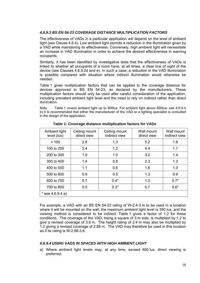
4.6.9.3 BS EN 54-23 COVERAGE DISTANCE MULTIPLICATION FACTORS The effectiveness of VADs in a particular application will depend on the level of ambient light (see Clause 4.6.4). Low ambient light permits a reduction in the illumination given by a VAD while maintaining its effectiveness. Conversely, high ambient light will necessitate an increase in VAD illumination in order to achieve the desired effectiveness in warning occupants.
Similarly, it has been identified by investigative tests that the effectiveness of VADs is linked to whether all occupants of a room have, at all times, a clear line of sight of the device (see Clauses 4.6.9.2d and e). In such a case, a reduction in the VAD illumination is possible compared with situation where indirect illumination would otherwise be needed.
Table 1 gives multiplication factors that can be applied to the coverage distance for devices approved to BS EN 54-23, as declared by the manufacturers. These multiplication factors should only be used after careful consideration of the application, including prevalent ambient light level and the need to rely on indirect rather than direct illumination.
Note Table 1 covers ambient light up to 800lux. For ambient light above 800lux- see 4.6.9.4 b) it is recommended that either the manufacturer of the VAD or a lighting specialist is consulted in the design of the application.
Table 1: Coverage distance multiplication factors for VADs
Ambient light level (lux)
Ceiling mount direct view
Ceiling mount indirect view
Wall mount direct view
Wall mount indirect view
< 100 2.8 1.3 5.2 1.8
100 to 200 2.4 1.2 4.4 1.7
200 to 300 1.9 1.0 3.2 1.4
300 to 400 1.4 0.8 2.3 1.2
400 to 500 1.1 0.6 1.8 1.0
500 to 600 0.9 0.5 1.3 0.9
600 to 700 0.7 0.4* 1.0 0.7*
700 to 800 0.5 0.3* 0.7 0.6*
* see 4.6.9.4 a)
For example, a VAD with an BS EN 54-23 rating of W-2.4-3 is to be used in a location where it will be mounted on the wall, the maximum ambient light level is 350 lux, and the viewing method is considered to be indirect. Table 1 gives a factor of 1.2 for these conditions. The coverage of the VAD, being a square of 3 m side, is multiplied by 1.2 to give a revised coverage of 3.6 m. The height rating of 2.4 m may also be multiplied by 1.2 giving a revised coverage of 2.88 m. The VAD may therefore be used in this location as if its rating is W-2.88-3,6.
4.6.9.4 USING VADS IN SPACES WITH HIGH AMBIENT LIGHT a) Where ambient light levels may, at any time, exceed 600 lux, direct viewing is
preferred;

19
b) In situations where lighting level greater than 800 lux is required, for example where highly demanding work such as minute assembly work is carried out, the selection and siting of VADs should be based on photometric calculations. Persons with specialist knowledge should be involved.
4.7 POWER SUPPLIES VADs, when operating, can place greater demands on power supplies than audible alarms. VADs, especially those based on xenon flash tube technology, may consume large amounts of power at start-up and then after each flash. These power demands, although short in duration, can affect operation of the power supply by exceeding its rated capacity and causing protective measures to operate. This can result in the VAD(s) failing to operate correctly, failing to flash or flashing irregularly, or for there to be a reduction of the power supplied to other parts of the system, causing a malfunction. The effect will be increased if several similar VADs are connected to the same supply and are synchronised in operation so that the current pulses from each VAD occur simultaneously. More recent designs of xenon VADs and those based on LED technology have better regulated power requirements, but the manufacturers’ data should be consulted to ensure compatibility between the power supply and the types and numbers of VADs to be used. In some instances, the power requirements of VADs will require localised or distributed power supplies to avoid voltage drop along cables. Addressable systems may require distributed power supplies as the power available directly from the system may be too limited to operate xenon VADs or higher output LED units directly from the loop. There should be compatibility between the VAD and power source to the device. Not all VADs will operate correctly from a pulsed power source. Power supplies should be compliant with BS EN 54-4 and the recommendations of BS 5839-1. In particular the following apply:
a) Both the normal and standby supply should each be independently capable of supplying the maximum alarm load imposed by the system, irrespective of the condition of the other supply. The high peak current loads which may be imposed by VADs should be taken into account;
b) The high peak power requirements of any VADs connected to a system should have no detrimental effect on the mandatory functions of the fire detection and fire alarm system;
c) Radio-linked VADs should comply with the power supply recommendations given in section 4.9;
d) Manufacturers of VADs and power supply equipment should make available sufficient information to allow the compatibility of power supplies to be assessed with special attention given to the handling of any high peak power requirements that may be generated by the VADs. NOTE: The manufacturer does not need to supply this with every product, but should make it available if requested

20
4.8 CABLES, WIRING AND OTHER INTERCONNECTIONS VADs form part of the primary means for giving warning of fire in particular circumstances, or for particular groups of people. It is, therefore, essential that circuits on which they are connected operate correctly at the time of a fire. It is not normally possible to predict, with any accuracy, those areas of a building in which fire can or cannot occur. At the design stage, the exact routes that cables of VADs will follow may also be unknown. Therefore, to ensure that cables used in circuits of VADs remain operational for an adequate duration, cables with an inherent ability to resist attack by fire need to be used. Accordingly, cables serving VADs should conform to the recommendations of sub-clause 26.2 of BS 5839-1 (as amended). It should be noted that this will necessitate that all cables satisfy the recommendations of sub-clause 26.2 for, at least, cables of standard fire resistance. However, in the circumstances described in sub-clause 26.2, cables of enhanced fire resistance will be necessary. 4.9 RADIO-LINKED SYSTEMS Where VADs are linked to CIE by radio communication, rather than wiring, there is a need for two-way communication between the VAD and the CIE; a radio signal from the CIE will trigger the operation of the VADs, while the VADs must be capable of transmitting a signal to the CIE for monitoring purposes. Some of the recommendations of this Loss Prevention Code of Practice, applicable to wired VADs, are unsuitable for, or cannot be applied to, radio-linked VADs. These include, in particular, those relating to power supplies and fault monitoring. Additional recommendations apply to radio-linked VADs in order to address the integrity and performance of the radio communications link between the VADs and the associated CIE. In practice, no system can have total reliability, but one of the objectives of good system design is to reduce the probability of the VADs being inoperative in the area of a fire when the fire starts. Exercising the VADs with testing and evacuation drills in excess of those recommended by the manufacturer can reduce the life of the radio-linked VAD batteries. It might be appropriate to stop the operation of VADs automatically to overcome the potential for undue discharge of VAD batteries. However, VADs with this facility should reactivate with any new fire or phased evacuation command. Such a facility should not impair the VADs’ ability to provide an adequate visual warning to the occupants of the building in the event of fire. Radio communications may also be used to link a small number of VADs to what is essentially a wired system. The recommendations of this Code of Practice apply equally to integral radio-linked VADs of this nature. Systems incorporating radio-linked VADs should comply with BS EN 54-25. The systems should also comply with all recommendations of this Code of Practice except that:
a) All radio-linked VADs should be supplied from at least two independent power supplies. These can be either: 1) The normal mains supply plus a reserve battery (primary or continuously
charged secondary); or, 2) A primary battery plus a second primary battery.
21
b) Power supplies incorporating one or more primary batteries should give 30 days
warning of impending battery failure. This should be indicated as a low battery warning condition at the CIE;
c) At the point at which the power supply(ies) to any VAD can maintain the VAD in normal operation for no more than seven days, and, in addition, 30 min in the alarm condition, a fault warning should be given at the CIE;
d) Primary power supplies should have a minimum, normal operational life of three years over the temperature range of +15ºC to +35ºC before the low power signal condition is signalled;
e) Any fault giving rise to loss of communication with a radio-linked VAD should be indicated at the CIE within two hours of occurrence of the fault.
Cables of antennae that are external to components of a radio-linked system should be monitored for open and short circuits. A fault condition should be given at the CIE within 100 s of the occurrence of such a condition. Cables of antennae that are external to the VAD, or to the CIE, should satisfy the recommendations of this Code of Practice for the fire resistance of cables. However, cables with lesser fire resistance may be used, provided they are routed through areas of low fire risk, or are protected against exposure to fire by burial in at least 12 mm of plaster or by separation from any fire risk by materials that would afford fire resistance of at least 30 min if tested in accordance with the relevant part of BS 476. Antennae should be so arranged that special tools are required for disconnection or removal of the outer housing. Facilities for automatic cessation of alarm signal of radio-linked VADs should comply with the recommendations of sub-clause 16.2.1h) of BS 5839-1 (as amended at the date of publication of this Code of Practice). A fault indication should be given within 100 s at the CIE if no valid radio transmissions are received from any VAD for two hours. After 30 s of continuous interference to the transmitted signal that can compromise the performance of any VAD, a fault indication should be given at the CIE within a further 100 s. Installation of radio-linked VADs should only take place after a comprehensive radio survey has been undertaken in accordance with the recommendations of sub-clause 27.2j) and 27.2k) of BS 5839-1 (as amended at the date of publication of this Code of Practice). At the time of commissioning, and after the installation of the VADs (and any remote antenna(e)), the records specified in sub-clause 27.2 l) of BS 5839-1 (as amended at the date of publication of this Code of Practice) should be completed. The signal levels recorded at commissioning should be within the specifications set by the manufacturer of the system. If not within the specification, appropriate remedial action should be undertaken. A copy of the signal levels should be kept on site with the system logbook. 4.10 ELECTROMAGNETIC COMPATIBILITY The installation of the VADs should comply with the recommendations of Clause 28 of BS 5839-1.

22
Particular attention should be given to the following:
• the susceptibility of the VAD to electromagnetic interference; • the level of screening afforded by the cable; • the separation distance between the fire alarm cables and the cables of other
services. Specific recommendations for EMC compliance given by the manufacturer of the VAD should be followed. 4.11 ELECTRICAL SAFETY As VADs are part of the fire alarm system, the recommendations of BS 7671 regarding safety and earthing are applicable to circuits serving VADs. LV and ELV circuits should be segregated in accordance with Clauses 26.2n) and 28 of BS 5839-1. If any ELV fire alarm cables share the same wiring containment with other cables, then the cable insulation of the fire cables should be rated for the highest voltage. Should the VAD be removable (e.g. from a base) and removal would expose, to touch, conductive parts at ELV potential, then, in wet conditions, such as swimming pools, saunas, abattoirs etc, one or more of the following should apply: • circuit voltages are less than 15V ripple free D.C. or 6 V A.C. r.m.s.; • a tool or special technique is necessary to remove parts to expose ELV parts; • the parts are positioned out of reach of persons other than authorized maintenance
personnel. Any separate power supply to VADs should comply with BS EN 54-4 and incorporate a safety isolating transformer conforming to the relevant parts of BS EN 61558. The transformer and power supply housing should be marked with the appropriate symbol, which should be easily visible and legible when inspecting or opening the equipment. It is also important for any mains (LV) power supply to have a double pole isolation facility near to the VAD supplied in order for maintenance engineers to isolate the circuits without the need to access remote parts of a building. The isolators should include a feature to enable them to be lockable to prevent unauthorized use in the normal or locked off position. 5 INSTALLATION 5.1 RESPONSIBILITY OF INSTALLER a) The installer should ensure that there is consultation with all relevant interested
parties that may include: • the user or purchaser; • the designer; • the supplier of the VADs; • consultants that include the architects, mechanical, lighting and electrical
consultants or fire engineering consultants. b) The installer should report and document any variations not clearly identified in the
documented design (other than errors or ‘snags’ for which rectification is proposed) – these variations may relate to circumstances that may have been unknown to the

23
designer e.g. change of structure of the building that will affect the effectiveness of the particular VADs being installed.
c) All metallic parts of the installation including conduit, trunking, ducting, cabling and
enclosures, should be separated from any metalwork forming part of a lightning protection system.
d) If it has been agreed that the installer is responsible for providing a set of ‘as fitted’
drawings, then all VADs should be incorporated with other fire detection and alarm devices.
e) Any mains supplies provided by the installer should comply with sub-clause 25.2
BS 5839-1. f) Any separate power supply units or standby power supplies, installed for use by
VADs, should comply with sections 25.3 and 25.4 of BS 5839-1, respectively. g) The installer should provide separate electrical installation certificates, as required
under BS 7671, for any separate mains supplies provided to support VADs h) On completion of the works, the installer should sign an Installation certificate of the
type recommended in Annex G2 of BS 5839-1. 5.2 INSTALLATION PRACTICES AND WORKMANSHIP a) The installation of the VADs should comply with the recommendations of sub-
clauses 37.1 and 37.2 of BS 5839-1. b) The recommendations of the VAD manufacturer on the correct mounting height and
orientation of VADs should be followed to ensure correct light dispersal and coverage is achieved to meet minimum light levels detailed in Clause 4.6)
c) VAD mounting bases should be provided with suitable ingress protection for the
mounting location and if necessary secure fittings to guard against potential tampering.
d) VADs should be sited so that they do not form a protruding object hazard. 5.3 INSPECTION AND TESTING OR WIRING Wiring should be inspected and tested in accordance with the recommendations of sub-clauses 38.1 and 38.2 of BS 5839-1.
6 COMMISSIONING 6.1 COMMISSIONING PROCEDURES Commissioning of VADs should be carried out in accordance with the recommendations of Clause 5 of BS 5839-1. In addition, it should be confirmed that:
a) the positioning and rating of VADs complies with Clause 4.6.9 and the system designer’s installation drawings;
b) all VADs used for indication of a fire alarm or the same phase of a multi stage
alarm arrangement are of the same colour throughout the site;

24
c) VADs cannot be confused with any other visual alarm signal within the building; d) where multiple VADs are visible from any single point, they should meet the
synchronisation requirements of sub-clauses 4.3.3 (g) and 4.5.5. 6.2 DOCUMENTATION In addition to the recommendations of Clause 40 of BS 5839-1, the documentation should also include “as fitted” drawings showing the location and light output ratings of all VADs in accordance with the formats specified in Clause 4.3.6.2 of BS EN 54-23. 6.3 CERTIFICATION, ACCEPTANCE AND VERIFICATION The certification, acceptance and verification processes recommended by BS 5839-1 apply. 7 MAINTENANCE 7.1 ROUTINE TESTING BS 5839-1 recommends that fire detection and fire alarm systems be tested every week. The main purpose of the weekly test is simply to ensure that there has not been a major failure of the entire system or a significant part of the system i.e. that the control equipment is capable of processing a fire alarm signal and providing an output to fire alarm devices (including VADs). Accordingly, it is not necessary to confirm that all circuits serving VADs operate correctly at the time of this test. However, routine testing of the system also provides an opportunity for occupants of the building to become, and remain, familiar with the visual alarm signals that the system produces. Accordingly, instructions to occupants should be that, at the time of the weekly test, any instance of poor visibility of visual alarm signals should be reported. In systems with staged alarms incorporating an ‘Alert’ and an ‘Evacuate’ visual alarm signal, the two signals should be operated, where practicable, sequentially in the order they would occur at the time of a fire (i.e. ‘Alert’ and then ‘Evacuate’). 7.2 INSPECTION AND SERVICING Inspection and servicing of equipment and circuits serving VADs, and the VADs themselves, should comply with the recommendations of Clause 45 of BS 5839-1. In particular, at the time of periodic inspection and test, the correct operation of all circuits serving VADs should be confirmed. Every year, the operation and, where applicable the synchronization, of each VAD should be checked, and, where necessary, the VAD lens should be cleaned to remove any dirt or deposits that would significantly decrease light output. It should also be confirmed that VADs are not obstructed from view. Note: The annual work described above may be carried out over the course of two or more service visits during each 12-month period. 7.3 NON-ROUTINE ATTENTION Non-routine attention includes special inspection on appointment of a new servicing

25
organisation, repair of faults or damage, inspection and test following any fire, and inspection and test following long periods of disconnection of the fire detection and fire alarm system. Non-routine attention should be carried out in accordance with the recommendations of Clause 46 of BS 5839-1. When a special inspection is carried out on appointment of a new servicing organisation, a significant failure of VADs to provide the coverage and illuminance levels recommended in Clause 4 should be regarded as a non-compliance that should be identified to the responsible person appointed by the user. It should be ensured that any organisation with which there is a contract for emergency call out to deal with any fault or damage to VADs or their circuits is competent to repair these devices and their circuits. After any fire, every VAD and VAD circuit that might have been affected by the fire should be inspected and tested in accordance with sub-clause 45.4 of BS 5839-1. In particular, VAD lenses should, where necessary, be cleaned to remove soot or other deposits. After any long period of disconnection, the recommendations for inspection and test of VADs and their circuits over a 12-month period should be undertaken. 7.4 MODIFICATIONS TO THE SYSTEM Modifications to VADs or their circuits should be carried out in accordance with the recommendations of sub-clause 46.4 of BS 5839-1. 8 USER RESPONSIBILITIES User responsibilities for VADs should be in accordance with the recommendations of Clause 47 of BS 5839-1. In particular, the person responsible for the system should ensure the following, namely that: • general fire notices include an explanation of the audible and visual warning system
in the event of a fire;
• all deaf and hard of hearing people are aware of the actions required in the event of a VAD activation;
• if a VAD is used for a staff alarm, people are adequately trained in the required
actions;
• if there are any changes to the layout or utilisation of a room or space that could result in reduced VAD effectiveness then the VAD installation design is reviewed;
• since all visual alarm signals produced by VADs within a building should have
similar characteristics, all additional or replacement VADs are compatible with those already present.
26
9 PUBLICATIONS REFERRED TO:
For undated references please refer to the latest published issue.
Reference number
Publication Year Title
1 Approved Document M
2004 Building Regulations 2000. Approved Document M
2 BS 476 (relevant parts)
- Fire tests on building materials and structures
3 BS EN 54-2 1997 Fire detection and fire alarm systems – Part 2: CIE
4 BS EN 54-4 1997 Fire detection and fire alarm systems – Part 4: Power supply equipment
5 BS EN 54-17 2005 Fire detection and fire alarm systems – Part 17: Short-circuit isolators
6 BS EN 54-23 2010 Fire detection and fire alarm systems – Part 23: Fire alarm devices – Visual Alarm Devices
7 BS EN 54-25 2008 Fire detection and fire alarm systems – Part 25: Components using radio links
8 BS 5839-1:2002 + A2:2008
2008 Part 1: Code of Practice for system design, installation, commissioning and maintenance
9 BS EN 60079-0 2009 Explosive atmospheres. Equipment. General requirements
10 BS EN 61241-0 2006 Electrical apparatus for use in the presence of combustible dust. General requirements
11 BS EN 61241-14 2004 Electrical apparatus for use in the presence of combustible dust. Selection and installation
12 BS EN 61241-17 2005 Electrical apparatus for use in the presence of combustible dust. Inspection and maintenance of electrical installations in hazardous areas
13 BS EN 61558 (relevant parts)
- Safety of power transformers, power supply units and similar products for supply voltages up to 1100 V
14 BS 667 2005 Illuminance meters — Requirements and test methods
15 BS 7273-1 2006 Code of Practice for the operation of fire protection measures. Electrical actuation of gaseous total flooding extinguishing systems
16 BS 7671 2008 Requirements for electrical installations. IEE Wiring Regulations. Seventeenth edition
17 BS 8300 2009+ A1:2010
Design of buildings and their approaches to meet the needs of disabled people. Code of Practice
18 BS 9999 2008 Code of Practice for fire safety in the design, management and use of buildings
19 DDA 1995 1995 Disability Discrimination Act 1995
20 Health and safety regulations
1996 The Health and Safety (Safety signs and signals) Regulations 1996
21 HTM 05-03:Part B
2006 Health Technical Memorandum 05-03: Operational provisions Part B - Fire detection and alarm systems
22 Regulatory Reform Order
2005 The Regulatory Reform (Fire Safety) Order 2005
23 CLEAR website Accessed March ‘12
http://learn.greenlux.org/packages/clear/visual/people/performance/lux.html
24 Wikipedia article on LUX
Accessed March ‘12 http://en.wikipedia.org/wiki/Lux

27
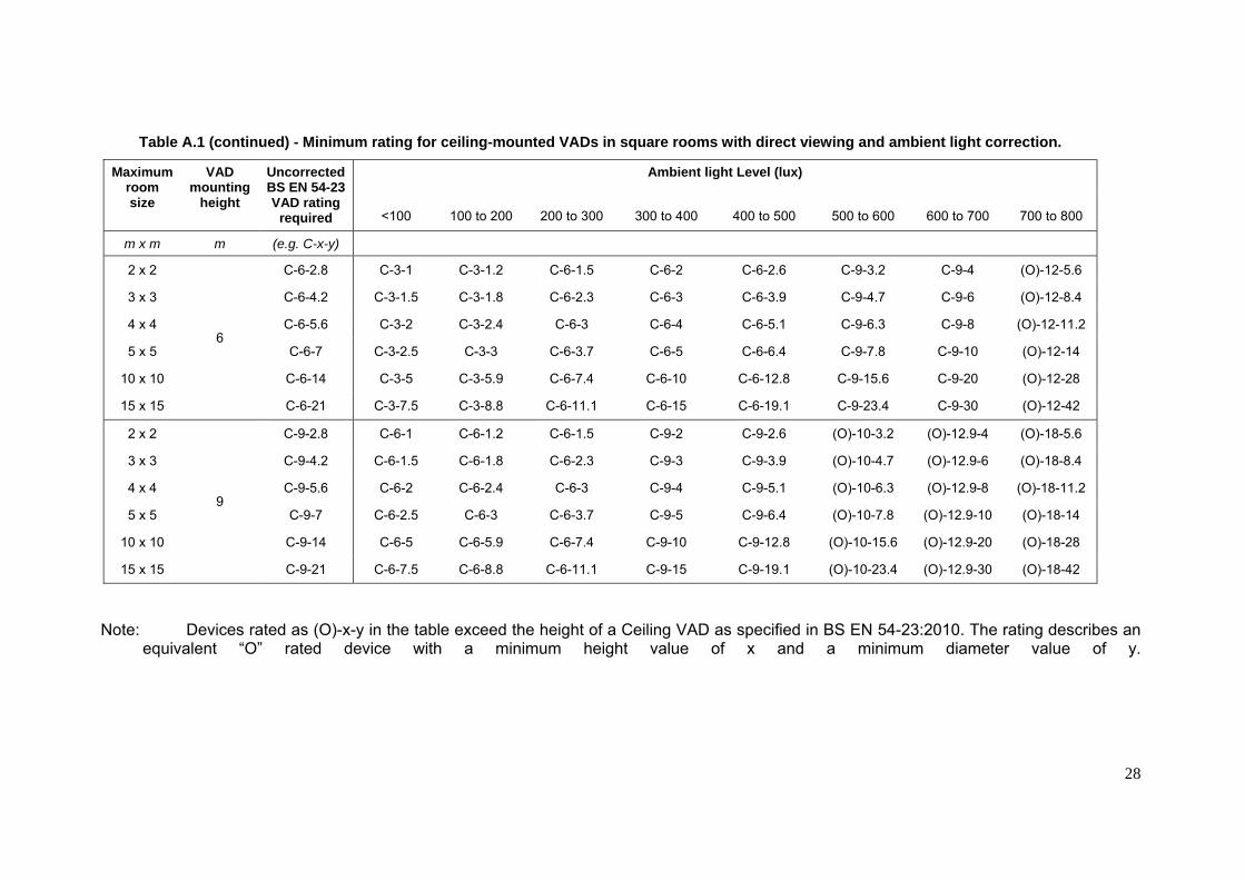
ANNEX A LOOK UP TABLES FOR VADS SITING IN PRE-DETERMINED DESIGN
A.1 INTRODUCTION Sub-clause 4.6.2 of this Code of Practice introduces two alternative approaches to the design of VAD installations. This Annex gives look-up tables that should be used when using the pre-determined design approach for rooms of simple geometry and frequently encountered ambient illumination. Tables are given for ceiling-mounted devices, wall-mounted devices and corridors.
A.2 CEILING-MOUNTED VADS
Table A.1 - Minimum rating for ceiling-mounted VADs in square rooms with direct viewing and ambient light correction.
Maximum room size
VAD mounting
height
Uncorrected BS EN 54-23 VAD rating
required
Ambient light Level (lux)
<100 100 to 200 200 to 300 300 to 400 400 to 500 500 to 600 600 to 700 700 to 800
m x m m (e.g. C-x-y)
2 x 2
3
C-3-2.8 C-3-1 C-3-1.2 C-3-1.5 C-3-2 C-3-2.6 C-6-3.2 C-6-4 C-6-5.6
3 x 3 C-3-4.2 C-3-1.5 C-3-1.8 C-3-2.3 C-3-3 C-3-3.9 C-6-4.7 C-6-6 C-6-8.4
4 x 4 C-3-5.6 C-3-2 C-3-2.4 C-3-3 C-3-4 C-3-5.1 C-6-6.3 C-6-8 C-6-11.2
5 x 5 C-3-7 C-3-2.5 C-3-3 C-3-3.7 C-3-5 C-3-6.4 C-6-7.8 C-6-10 C-6-14
10 x 10 C-3-14 C-3-5 C-3-5.9 C-3-7.4 C-3-10 C-3-12.8 C-6-15.6 C-6-20 C-6-28
15 x 15 C-3-21 C-3-7.5 C-3-8.8 C-3-11.1 C-3-15 C-3-19.1 C-6-23.4 C-6-30 C-6-42
28
Table A.1 (continued) - Minimum rating for ceiling-mounted VADs in square rooms with direct viewing and ambient light correction.
Maximum room size
VAD mounting
height
Uncorrected BS EN 54-23 VAD rating
required
Ambient light Level (lux)
<100 100 to 200 200 to 300 300 to 400 400 to 500 500 to 600 600 to 700 700 to 800
m x m m (e.g. C-x-y)
2 x 2
6
C-6-2.8 C-3-1 C-3-1.2 C-6-1.5 C-6-2 C-6-2.6 C-9-3.2 C-9-4 (O)-12-5.6
3 x 3 C-6-4.2 C-3-1.5 C-3-1.8 C-6-2.3 C-6-3 C-6-3.9 C-9-4.7 C-9-6 (O)-12-8.4
4 x 4 C-6-5.6 C-3-2 C-3-2.4 C-6-3 C-6-4 C-6-5.1 C-9-6.3 C-9-8 (O)-12-11.2
5 x 5 C-6-7 C-3-2.5 C-3-3 C-6-3.7 C-6-5 C-6-6.4 C-9-7.8 C-9-10 (O)-12-14
10 x 10 C-6-14 C-3-5 C-3-5.9 C-6-7.4 C-6-10 C-6-12.8 C-9-15.6 C-9-20 (O)-12-28
15 x 15 C-6-21 C-3-7.5 C-3-8.8 C-6-11.1 C-6-15 C-6-19.1 C-9-23.4 C-9-30 (O)-12-42
2 x 2
9
C-9-2.8 C-6-1 C-6-1.2 C-6-1.5 C-9-2 C-9-2.6 (O)-10-3.2 (O)-12.9-4 (O)-18-5.6
3 x 3 C-9-4.2 C-6-1.5 C-6-1.8 C-6-2.3 C-9-3 C-9-3.9 (O)-10-4.7 (O)-12.9-6 (O)-18-8.4
4 x 4 C-9-5.6 C-6-2 C-6-2.4 C-6-3 C-9-4 C-9-5.1 (O)-10-6.3 (O)-12.9-8 (O)-18-11.2
5 x 5 C-9-7 C-6-2.5 C-6-3 C-6-3.7 C-9-5 C-9-6.4 (O)-10-7.8 (O)-12.9-10 (O)-18-14
10 x 10 C-9-14 C-6-5 C-6-5.9 C-6-7.4 C-9-10 C-9-12.8 (O)-10-15.6 (O)-12.9-20 (O)-18-28
15 x 15 C-9-21 C-6-7.5 C-6-8.8 C-6-11.1 C-9-15 C-9-19.1 (O)-10-23.4 (O)-12.9-30 (O)-18-42
Note: Devices rated as (O)-x-y in the table exceed the height of a Ceiling VAD as specified in BS EN 54-23:2010. The rating describes an equivalent “O” rated device with a minimum height value of x and a minimum diameter value of y.

29
Table A.2 - Minimum rating for ceiling-mounted VADs in square rooms with indirect viewing and ambient light correction.
Maximum room size
VAD mounting
height
Uncorrected BS EN 54-23 VAD rating
required
Ambient light Level (lux)
<100 100 to 200 200 to 300 300 to 400 400 to 500 500 to 600 600 to 700 700 to 800
m x m m (e.g. C-x-y)
2 x 2
3
C-3-2.8 C-3-2.2 C-3-2.4 C-3-2.8 C-6-3.5 C-6-4.7 C-6-5.6 C-9-7 (O)-10-9.4
3 x 3 C-3-4.2 C-3-3.3 C-3-3.5 C-3-4.2 C-6-5.3 C-6-7 C-6-8.4 C-9-10.5 (O)-10-14
4 x 4 C-3-5.6 C-3-4.4 C-3-4.7 C-3-5.6 C-6-7 C-6-9.4 C-6-11.2 C-9-14 (O)-10-18.7
5 x 5 C-3-7 C-3-5.4 C-3-5.9 C-3-7 C-6-8.8 C-6-11.7 C-6-14 C-9-17.5 (O)-10-23.4
10 x 10 C-3-14 C-3-10.8 C-3-11.7 C-3-14 C-6-17.5 C-6-23.4 C-6-28 C-9-35 (O)-10-46.7
15 x 15 C-3-21 C-3-16.2 C-3-17.5 C-3-21 C-6-26.3 C-6-35 C-6-42 C-9-52.5 (O)-10-70
2 x 2
6
C-6-2.8 C-6-2.2 C-6-2.4 C-6-2.8 C-9-3.5 (O)-10-4.7 (O)-12-5.6 (O)-15-7 (O)-20-9.4
3 x 3 C-6-4.2 C-6-3.3 C-6-3.5 C-6-4.2 C-9-5.3 (O)-10-7 (O)-12-8.4 (O)-15-10.5 (O)-20-14
4 x 4 C-6-5.6 C-6-4.4 C-6-4.7 C-6-5.6 C-9-7 (O)-10-9.4 (O)-12-11.2 (O)-15-14 (O)-20-18.7
5 x 5 C-6-7 C-6-5.4 C-6-5.9 C-6-7 C-9-8.8 (O)-10-11.7 (O)-12-14 (O)-15-17.5 (O)-20-23.4
10 x 10 C-6-14 C-6-10.8 C-6-11.7 C-6-14 C-9-17.5 (O)-10-23.4 (O)-12-28 (O)-15-35 (O)-20-46.7
15 x 15 C-6-21 C-6-16.2 C-6-17.5 C-6-21 C-9-26.3 (O)-10-35 (O)-12-42 (O)-15-52.5 (O)-20-70

30
Table A.2 (continued)- Minimum rating for ceiling-mounted VADs in square rooms with indirect viewing and ambient light correction.
Maximum room size
VAD mounting
height
Uncorrected BS EN 54-23 VAD rating
required
Ambient light Level (lux)
<100 100 to 200 200 to 300 300 to 400 400 to 500 500 to 600 600 to 700 700 to 800
m x m m (e.g. C-x-y)
2 x 2
9
C-9-2.8 C-9-2.2 C-9-2.4 C-9-2.8 (O)-11.3-3.5 (O)-15-4.7 (O)-18-5.6 (O)-22.5-7 (O)-30-9.4
3 x 3 C-9-4.2 C-9-3.3 C-9-3.5 C-9-4.2 (O)-11.3-5.3 (O)-15-7 (O)-18-8.4 (O)-22.5-10.5 (O)-30-14
4 x 4 C-9-5.6 C-9-4.4 C-9-4.7 C-9-5.6 (O)-11.3-7 (O)-15-9.4 (O)-18-11.2 (O)-22.5-14 (O)-30-18.7
5 x 5 C-9-7 C-9-5.4 C-9-5.9 C-9-7 (O)-11.3-8.8 (O)-15-11.7 (O)-18-14 (O)-22.5-17.5 (O)-30-23.4
10 x 10 C-9-14 C-9-10.8 C-9-11.7 C-9-14 (O)-11.3-17.5 (O)-15-23.4 (O)-18-28 (O)-22.5-35 (O)-30-46.7
15 x 15 C-9-21 C-9-16.2 C-9-17.5 C-9-21 (O)-11.3-26.3 (O)-15-35 (O)-18-42 (O)-22.5-52.5 (O)-30-70
Note: Devices rated as (O)-x-y in the table exceed the height of a Ceiling VAD as specified in BS EN 54-23:2010. The rating describes an equivalent “O” rated device with a minimum height value of x and a minimum diameter value of y.

31
Table A.3 - Minimum rating for Ceiling VADs in corridors mounted at the mid-point with direct viewing and ambient light correction. Maximum corridor
size
VAD mounting
height
Uncorrected BS EN 54-23 VAD rating
required
Ambient light Level (lux)
<100 100 to 200 200 to 300 300 to 400 400 to 500 500 to 600 600 to 700 700 to 800
m x m m (e.g. C-x-y)
3 x 1.5
3
C-3-3.4 C-3-1.3 C-3-1.5 C-3-1.8 C-3-2.5 C-3-3.1 C-6-3.8 C-6-4.9 C-6-6.8
4 x 1.5 C-3-4.3 C-3-1.6 C-3-1.8 C-3-2.3 C-3-3.1 C-3-4 C-6-4.8 C-6-6.2 C-6-8.6
5 x 1.5 C-3-5.2 C-3-1.9 C-3-2.2 C-3-2.8 C-3-3.8 C-3-4.8 C-6-5.8 C-6-7.5 C-6-10.4
10 x 1.5 C-3-10.1 C-3-3.7 C-3-4.3 C-3-5.4 C-3-7.3 C-3-9.2 C-6-11.3 C-6-14.5 C-6-20.2
15 x 1.5 C-3-15 C-3-5.4 C-3-6.3 C-3-7.9 C-3-10.8 C-3-13.7 C-6-16.7 C-6-21.5 C-6-30
3 x 2
3
C-3-3.6 C-3-1.3 C-3-1.5 C-3-1.9 C-3-2.6 C-3-3.3 C-6-4 C-6-5.2 C-6-7.2
4 x 2 C-3-4.5 C-3-1.7 C-3-1.9 C-3-2.4 C-3-3.3 C-3-4.1 C-6-5 C-6-6.5 C-6-9
5 x 2 C-3-5.4 C-3-2 C-3-2.3 C-3-2.9 C-3-3.9 C-3-5 C-6-6 C-6-7.8 C-6-10.8
10 x 2 C-3-10.2 C-3-3.7 C-3-4.3 C-3-5.4 C-3-7.3 C-3-9.3 C-6-11.4 C-6-14.6 C-6-20.4
15 x 2 C-3-15.1 C-3-5.4 C-3-6.3 C-3-8 C-3-10.8 C-3-13.8 C-6-16.8 C-6-21.6 C-6-30.2
2 x 2.5
3
C-3-3.2 C-3-1.2 C-3-1.4 C-3-1.7 C-3-2.3 C-3-3 C-6-3.6 C-6-4.6 C-6-6.4
3 x 2.5 C-3-3.9 C-3-1.4 C-3-1.7 C-3-2.1 C-3-2.8 C-3-3.6 C-6-4.4 C-6-5.6 C-6-7.8
4 x 2.5 C-3-4.7 C-3-1.7 C-3-2 C-3-2.5 C-3-3.4 C-3-4.3 C-6-5.3 C-6-6.8 C-6-9.4
5 x 2.5 C-3-5.6 C-3-2 C-3-2.4 C-3-3 C-3-4 C-3-5.1 C-6-6.3 C-6-8 C-6-11.2
10 x 2.5 C-3-10.3 C-3-3.7 C-3-4.3 C-3-5.5 C-3-7.4 C-3-9.4 C-6-11.5 C-6-14.8 C-6-20.6
15 x 2.5 C-3-15.2 C-3-5.5 C-3-6.4 C-3-8 C-3-10.9 C-3-13.9 C-6-16.9 C-6-21.8 C-6-30.4
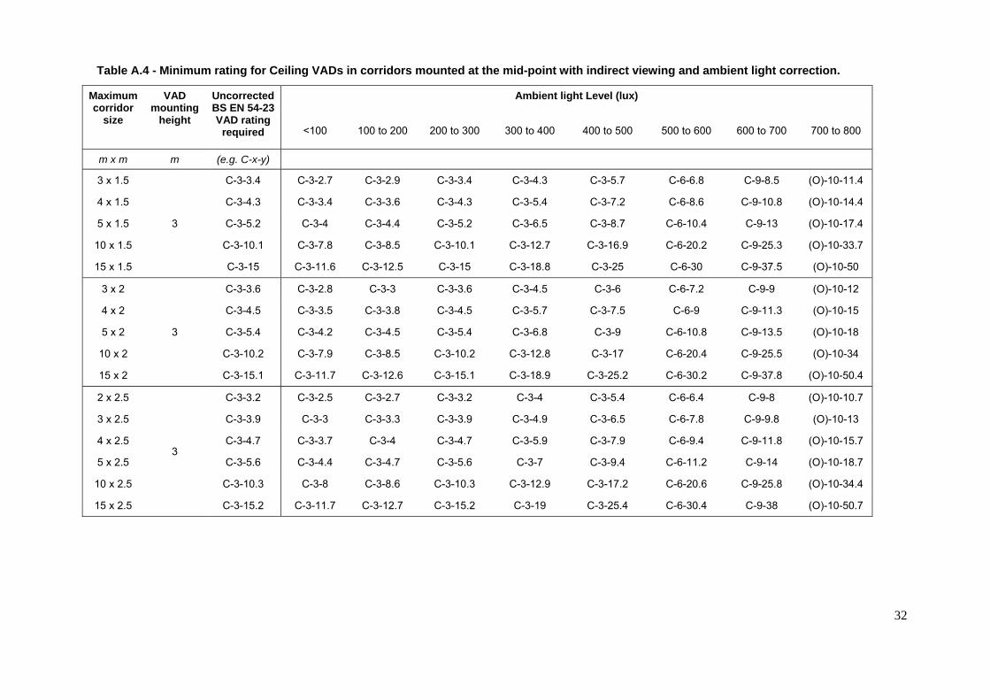
32
Table A.4 - Minimum rating for Ceiling VADs in corridors mounted at the mid-point with indirect viewing and ambient light correction.
Maximum corridor
size
VAD mounting
height
Uncorrected BS EN 54-23 VAD rating
required
Ambient light Level (lux)
<100 100 to 200 200 to 300 300 to 400 400 to 500 500 to 600 600 to 700 700 to 800
m x m m (e.g. C-x-y)
3 x 1.5
3
C-3-3.4 C-3-2.7 C-3-2.9 C-3-3.4 C-3-4.3 C-3-5.7 C-6-6.8 C-9-8.5 (O)-10-11.4
4 x 1.5 C-3-4.3 C-3-3.4 C-3-3.6 C-3-4.3 C-3-5.4 C-3-7.2 C-6-8.6 C-9-10.8 (O)-10-14.4
5 x 1.5 C-3-5.2 C-3-4 C-3-4.4 C-3-5.2 C-3-6.5 C-3-8.7 C-6-10.4 C-9-13 (O)-10-17.4
10 x 1.5 C-3-10.1 C-3-7.8 C-3-8.5 C-3-10.1 C-3-12.7 C-3-16.9 C-6-20.2 C-9-25.3 (O)-10-33.7
15 x 1.5 C-3-15 C-3-11.6 C-3-12.5 C-3-15 C-3-18.8 C-3-25 C-6-30 C-9-37.5 (O)-10-50
3 x 2
3
C-3-3.6 C-3-2.8 C-3-3 C-3-3.6 C-3-4.5 C-3-6 C-6-7.2 C-9-9 (O)-10-12
4 x 2 C-3-4.5 C-3-3.5 C-3-3.8 C-3-4.5 C-3-5.7 C-3-7.5 C-6-9 C-9-11.3 (O)-10-15
5 x 2 C-3-5.4 C-3-4.2 C-3-4.5 C-3-5.4 C-3-6.8 C-3-9 C-6-10.8 C-9-13.5 (O)-10-18
10 x 2 C-3-10.2 C-3-7.9 C-3-8.5 C-3-10.2 C-3-12.8 C-3-17 C-6-20.4 C-9-25.5 (O)-10-34
15 x 2 C-3-15.1 C-3-11.7 C-3-12.6 C-3-15.1 C-3-18.9 C-3-25.2 C-6-30.2 C-9-37.8 (O)-10-50.4
2 x 2.5
3
C-3-3.2 C-3-2.5 C-3-2.7 C-3-3.2 C-3-4 C-3-5.4 C-6-6.4 C-9-8 (O)-10-10.7
3 x 2.5 C-3-3.9 C-3-3 C-3-3.3 C-3-3.9 C-3-4.9 C-3-6.5 C-6-7.8 C-9-9.8 (O)-10-13
4 x 2.5 C-3-4.7 C-3-3.7 C-3-4 C-3-4.7 C-3-5.9 C-3-7.9 C-6-9.4 C-9-11.8 (O)-10-15.7
5 x 2.5 C-3-5.6 C-3-4.4 C-3-4.7 C-3-5.6 C-3-7 C-3-9.4 C-6-11.2 C-9-14 (O)-10-18.7
10 x 2.5 C-3-10.3 C-3-8 C-3-8.6 C-3-10.3 C-3-12.9 C-3-17.2 C-6-20.6 C-9-25.8 (O)-10-34.4
15 x 2.5 C-3-15.2 C-3-11.7 C-3-12.7 C-3-15.2 C-3-19 C-3-25.4 C-6-30.4 C-9-38 (O)-10-50.7

33
A.3 WALL-MOUNTED VADS
Table A.5 - Minimum rating for wall-mounted VADs at 2.4m in square and oblong rooms with direct viewing and ambient light correction. Maximum
room size
Number of VADs
used
Uncorrected BS EN 54-23 VAD rating
required
Ambient light Level (lux)
<100 100 to 200 200 to 300 300 to 400 400 to 500 500 to 600 600 to 700 700 to 800
m x m (eg. W–x–y)
2 x 2
1a)
W–2.4–2 W–2.4–0.4 W-2.4-0.5 W-2.4-0.7 W-2.4-0.9 W-2.4-1.2 W-2.4-1.6 W-2.4-2 W-3.4-2.9 4 x 4 W–2.4–4 W-2.4-0.8 W-2.4-1 W-2.4-1.3 W-2.4-1.8 W-2.4-2.3 W-2.4-3.1 W-2.4-4 W-3.4-5.8 6 x 6 W–2.4–6 W-2.4-1.2 W-2.4-1.4 W-2.4-1.9 W-2.4-2.7 W-2.4-3.4 W-2.4-4.7 W-2.4-6 W-3.4-8.6 9 x 9 W–2.4–9 W-2.4-1.8 W-2.4-2.1 W-2.4-2.9 W-2.4-4 W-2.4-5 W-2.4-7 W-2.4-9 W-3.4-12.9
12 x 12 W–2.4–12 W-2.4-2.4 W-2.4-2.8 W-2.4-3.8 W-2.4-5.3 W-2.4-6.7 W-2.4-9.3 W-2.4-12 W-3.4-17.2 15 x 15 W–2.4–15 W-2.4-2.9 W-2.4-3.5 W-2.4-4.7 W-2.4-6.6 W-2.4-8.4 W-2.4-11.6 W-2.4-15 W-3.4-21.5 18 x 18 W–2.4–18 W-2.4-3.5 W-2.4-4.1 W-2.4-5.7 W-2.4-7.9 W-2.4-10 W-2.4-13.9 W-2.4-18 W-3.4-25.8 21 x 21 W–2.4–21 W-2.4-4.1 W-2.4-4.8 W-2.4-6.6 W-2.4-9.2 W-2.4-11.7 W-2.4-16.2 W-2.4-21 W-3.4-30 24 x 24 W–2.4–24 W-2.4-4.7 W-2.4-5.5 W-2.4-7.5 W-2.4-10.5 W-2.4-13.4 W-2.4-18.5 W-2.4-24 W-3.4-34.3
4 x 2
2b)
W-2.4-2 W–2.4–0.4 W-2.4-0.5 W-2.4-0.7 W-2.4-0.9 W-2.4-1.2 W-2.4-1.6 W-2.4-2 W-3.4-2.9 8 x 4 W-2.4-4 W-2.4-0.8 W-2.4-1 W-2.4-1.3 W-2.4-1.8 W-2.4-2.3 W-2.4-3.1 W-2.4-4 W-3.4-5.8
12 x 6 W-2.4-6 W-2.4-1.2 W-2.4-1.4 W-2.4-1.9 W-2.4-2.7 W-2.4-3.4 W-2.4-4.7 W-2.4-6 W-3.4-8.6 15 x 7.5 W-2.4-7.5 W-2.4-1.5 W-2.4-1.8 W-2.4-2.4 W-2.4-3.3 W-2.4-4.2 W-2.4-5.8 W-2.4-7.5 W-3.4-10.8 18 x 9 W-2.4-9 W-2.4-1.8 W-2.4-2.1 W-2.4-2.9 W-2.4-4 W-2.4-5 W-2.4-7 W-2.4-9 W-3.4-12.9
21 x 10.5 W-2.4-10.5 W-2.4-2.1 W-2.4-2.4 W-2.4-3.3 W-2.4-4.6 W-2.4-5.9 W-2.4-8.1 W-2.4-10.5 W-3.4-15 24 x 12 W-2.4-12 W-2.4-2.4 W-2.4-2.8 W-2.4-3.8 W-2.4-5.3 W-2.4-6.7 W-2.4-9.3 W-2.4-12 W-3.4-17.2 28 x 14 W-2.4-14 W-2.4-2.7 W-2.4-3.2 W-2.4-4.4 W-2.4-6.1 W-2.4-7.8 W-2.4-10.8 W-2.4-14 W-3.4-20 36 x 18 W-2.4-18 W-2.4-3.5 W-2.4-4.1 W-2.4-5.7 W-2.4-7.9 W-2.4-10 W-2.4-13.9 W-2.4-18 W-3.4-25.8

34
Table A.5 (continued) - Minimum rating for wall-mounted VADs at 2.4m in square and oblong rooms with direct viewing and ambient light
correction. Maximum
room size
Number of VADs
used
Uncorrected BS EN 54-23 VAD rating
required
Ambient light Level (lux)
<100 100 to 200 200 to 300 300 to 400 400 to 500 500 to 600 600 to 700 700 to 800
m x m (eg. W–x–y)
4 x 4
4c)
W-2.4-2 W–2.4–0.4 W–2.4–0.5 W–2.4–0.7 W–2.4–0.9 W–2.4–1.2 W–2.4–1.6 W–2.4–2 W-3.4-2.9 6 x 6 W-2.4-3 W-2.4-0.6 W-2.4-0.7 W-2.4-1 W-2.4-1.4 W-2.4-1.7 W-2.4-2.4 W-2.4-3 W-3.4-4.3 9 x 9 W-2.4-4.5 W-2.4-0.9 W-2.4-1.1 W-2.4-1.5 W-2.4-2 W-2.4-2.5 W-2.4-3.5 W-2.4-4.5 W-3.4-6.5
15 x 15 W-2.4-7.5 W-2.4-1.5 W-2.4-1.8 W-2.4-2.4 W-2.4-3.3 W-2.4-4.2 W-2.4-5.8 W-2.4-7.5 W-3.4-10.8 18 x 18 W-2.4-9 W-2.4-1.8 W-2.4-2.1 W-2.4-2.9 W-2.4-4 W-2.4-5 W-2.4-7 W-2.4-9 W-3.4-12.9 21 x 21 W-2.4-10.5 W-2.4-2.1 W-2.4-2.4 W-2.4-3.3 W-2.4-4.6 W-2.4-5.9 W-2.4-8.1 W-2.4-10.5 W-3.4-15 24 x 24 W-2.4-12 W-2.4-2.4 W-2.4-2.8 W-2.4-3.8 W-2.4-5.3 W-2.4-6.7 W-2.4-9.3 W-2.4-12 W-3.4-17.2 28 x 28 W-2.4-14 W-2.4-2.7 W-2.4-3.2 W-2.4-4.4 W-2.4-6.1 W-2.4-7.8 W-2.4-10.8 W-2.4-14 W-3.4-20 32 x 32 W-2.4-16 W-2.4-3.1 W-2.4-3.7 W-2.4-5 W-2.4-7 W-2.4-8.9 W-2.4-12.4 W-2.4-16 W-3.4-22.9

35
Table A.6 - Minimum rating for wall-mounted VADs at 2.4m in square and oblong rooms with indirect viewing and ambient light correction. Maximum
room size
Number of
VADs used
Uncorrected BS EN 54-23 VAD rating
required
Ambient light Level (lux)
<100 100 to 200 200 to 300 300 to 400 400 to 500 500 to 600 600 to 700 700 to 800
m x m (eg. W–x–y)
2 x 2
1a)
W–2.4–2 W–2.4–1.2 W-2.4-1.2 W-2.4-1.5 W-2.4-1.7 W-2.4-2 W-2.7-2.3 W-3.4-2.9 W-4-3.4 4 x 4 W–2.4–4 W-2.4-2.3 W-2.4-2.4 W-2.4-2.9 W-2.4-3.4 W-2.4-4 W-2.7-4.5 W-3.4-5.8 W-4-6.7 6 x 6 W–2.4–6 W-2.4-3.4 W-2.4-3.6 W-2.4-4.3 W-2.4-5 W-2.4-6 W-2.7-6.7 W-3.4-8.6 W-4-10 9 x 9 W–2.4–9 W-2.4-5 W-2.4-5.3 W-2.4-6.5 W-2.4-7.5 W-2.4-9 W-2.7-10 W-3.4-12.9 W-4-15
12 x 12 W–2.4–12 W-2.4-6.7 W-2.4-7.1 W-2.4-8.6 W-2.4-10 W-2.4-12 W-2.7-13.4 W-3.4-17.2 W-4-20 15 x 15 W–2.4–15 W-2.4-8.4 W-2.4-8.9 W-2.4-10.8 W-2.4-12.5 W-2.4-15 W-2.7-16.7 W-3.4-21.5 W-4-25 18 x 18 W–2.4–18 W-2.4-10 W-2.4-10.6 W-2.4-12.9 W-2.4-15 W-2.4-18 W-2.7-20 W-3.4-25.8 W-4-30 21 x 21 W–2.4–21 W-2.4-11.7 W-2.4-12.4 W-2.4-15 W-2.4-17.5 W-2.4-21 W-2.7-23.4 W-3.4-30 W-4-35 24 x 24 W–2.4–24 W-2.4-13.4 W-2.4-14.2 W-2.4-17.2 W-2.4-20 W-2.4-24 W-2.7-26.7 W-3.4-34.3 W-4-40
4 x 2
2b)
W-2.4-2 W–2.4–1.2 W-2.4-1.2 W-2.4-1.5 W-2.4-1.7 W-2.4-2 W-2.7-2.3 W-3.4-2.9 W-4-3.4 8 x 4 W-2.4-4 W-2.4-2.3 W-2.4-2.4 W-2.4-2.9 W-2.4-3.4 W-2.4-4 W-2.7-4.5 W-3.4-5.8 W-4-6.7
12 x 6 W-2.4-6 W-2.4-3.4 W-2.4-3.6 W-2.4-4.3 W-2.4-5.0 W-2.4-6 W-2.7-6.7 W-3.4-8.6 W-4-10 15 x 7.5 W-2.4-7.5 W-2.4-4.2 W-2.4-4.5 W-2.4-5.4 W-2.4-6.3 W-2.4-7.5 W-2.7-8.4 W-3.4-10.8 W-4-12.5 18 x 9 W-2.4-9 W-2.4-5 W-2.4-5.3 W-2.4-6.5 W-2.4-7.5 W-2.4-9 W-2.7-10 W-3.4-12.9 W-4-15
21 x 10.5 W-2.4-10.5 W-2.4-5.9 W-2.4-6.2 W-2.4-7.5 W-2.4-8.8 W-2.4-10.5 W-2.7-11.7 W-3.4-15 W-4-17.5 24 x 12 W-2.4-12 W-2.4-6.7 W-2.4-7.1 W-2.4-8.6 W-2.4-10 W-2.4-12 W-2.7-13.4 W-3.4-17.2 W-4-20 28 x 14 W-2.4-14 W-2.4-7.8 W-2.4-8.3 W-2.4-10 W-2.4-11.7 W-2.4-14 W-2.7-15.6 W-3.4-20 W-4-23.4 36 x 18 W-2.4-18 W-2.4-10 W-2.4-10.6 W-2.4-12.9 W-2.4-15.0 W-2.4-18 W-2.7-20 W-3.4-25.8 W-4-30
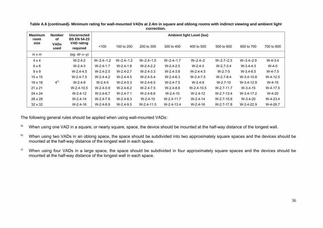
36
Table A.6 (continued)- Minimum rating for wall-mounted VADs at 2.4m in square and oblong rooms with indirect viewing and ambient light correction.
Maximum room size
Number of
VADs used
Uncorrected BS EN 54-23 VAD rating
required
Ambient light Level (lux)
<100 100 to 200 200 to 300 300 to 400 400 to 500 500 to 600 600 to 700 700 to 800
m x m (eg. W–x–y)
4 x 4
4c)
W-2.4-2 W–2.4–1.2 W–2.4–1.2 W–2.4–1.5 W–2.4–1.7 W–2.4–2 W–2.7–2.3 W–3.4–2.9 W-4-3.4 6 x 6 W-2.4-3 W-2.4-1.7 W-2.4-1.8 W-2.4-2.2 W-2.4-2.5 W-2.4-3 W-2.7-3.4 W-3.4-4.3 W-4-5 9 x 9 W-2.4-4.5 W-2.4-2.5 W-2.4-2.7 W-2.4-3.3 W-2.4-3.8 W-2.4-4.5 W-2.7-5 W-3.4-6.5 W-4-7.5
15 x 15 W-2.4-7.5 W-2.4-4.2 W-2.4-4.5 W-2.4-5.4 W-2.4-6.3 W-2.4-7.5 W-2.7-8.4 W-3.4-10.8 W-4-12.5 18 x 18 W-2.4-9 W-2.4-5 W-2.4-5.3 W-2.4-6.5 W-2.4-7.5 W-2.4-9 W-2.7-10 W-3.4-12.9 W-4-15 21 x 21 W-2.4-10.5 W-2.4-5.9 W-2.4-6.2 W-2.4-7.5 W-2.4-8.8 W-2.4-10.5 W-2.7-11.7 W-3.4-15 W-4-17.5 24 x 24 W-2.4-12 W-2.4-6.7 W-2.4-7.1 W-2.4-8.6 W-2.4-10 W-2.4-12 W-2.7-13.4 W-3.4-17.2 W-4-20 28 x 28 W-2.4-14 W-2.4-7.8 W-2.4-8.3 W-2.4-10 W-2.4-11.7 W-2.4-14 W-2.7-15.6 W-3.4-20 W-4-23.4 32 x 32 W-2.4-16 W-2.4-8.9 W-2.4-9.5 W-2.4-11.5 W-2.4-13.4 W-2.4-16 W-2.7-17.8 W-3.4-22.9 W-4-26.7
The following general rules should be applied when using wall-mounted VADs:
a) When using one VAD in a square, or nearly square, space, the device should be mounted at the half-way distance of the longest wall.
b) When using two VADs in an oblong space, the space should be subdivided into two approximately square spaces and the devices should be mounted at the half-way distance of the longest wall in each space.
c) When using four VADs in a large space, the space should be subdivided in four approximately square spaces and the devices should be mounted at the half-way distance of the longest wall in each space.

37
Table A.7 - Minimum rating for wall-mounted VADs at 2.4m in corridors with direct viewing and ambient light correction. Maximum corridor
size
Number of
VADs used
Uncorrected BS EN 54-23 VAD rating
required
Ambient light Level (lux)
<100 100 to 200 200 to 300 300 to 400 400 to 500 500 to 600 600 to 700 700 to 800
m x m (eg. W–x–y)
2 x 2
1a)
W-2.4-2 W-2.4-0.4 W-2.4-0.5 W-2.4-0.7 W-2.4-0.9 W-2.4-1.2 W-2.4-1.6 W-2.4-2 W-3.4-2.9
3 x 2 W-2.4-3 W-2.4-0.6 W-2.4-0.7 W-2.4-1 W-2.4-1.4 W-2.4-1.7 W-2.4-2.4 W-2.4-3 W-3.4-4.3
4 x 2 W-2.4-4 W-2.4-0.8 W-2.4-1 W-2.4-1.3 W-2.4-1.8 W-2.4-2.3 W-2.4-3.1 W-2.4-4 W-3.4-5.8
5 x 2 W-2.4-5 W-2.4-1 W-2.4-1.2 W-2.4-1.6 W-2.4-2.2 W-2.4-2.8 W-2.4-3.9 W-2.4-5 W-3.4-7.2
6 x 2 W-2.4-6 W-2.4-1.2 W-2.4-1.4 W-2.4-1.9 W-2.4-2.7 W-2.4-3.4 W-2.4-4.7 W-2.4-6 W-3.4-8.6
9 x 2 W-2.4-9 W-2.4-1.8 W-2.4-2.1 W-2.4-2.9 W-2.4-4 W-2.4-5 W-2.4-7 W-2.4-9 W-3.4-12.9
12 x 2 W-2.4-12 W-2.4-2.4 W-2.4-2.8 W-2.4-3.8 W-2.4-5.3 W-2.4-6.7 W-2.4-9.3 W-2.4-12 W-3.4-17.2
15 x 2 W-2.4-15 W-2.4-2.9 W-2.4-3.5 W-2.4-4.7 W-2.4-6.6 W-2.4-8.4 W-2.4-11.6 W-2.4-15 W-3.4-21.5
18 x 2 W-2.4-18 W-2.4-3.5 W-2.4-4.1 W-2.4-5.7 W-2.4-7.9 W-2.4-10 W-2.4-13.9 W-2.4-18 W-3.4-25.8
24 x 2 W-2.4-24 W-2.4-4.7 W-2.4-5.5 W-2.4-7.5 W-2.4-10.5 W-2.4-13.4 W-2.4-18.5 W-2.4-24 W-3.4-34.3
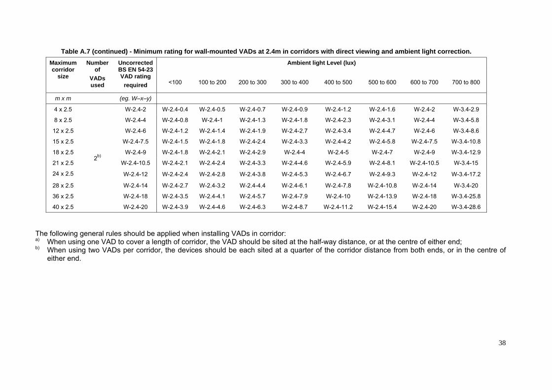
38
Table A.7 (continued) - Minimum rating for wall-mounted VADs at 2.4m in corridors with direct viewing and ambient light correction.
Maximum corridor
size
Number of
VADs used
Uncorrected BS EN 54-23 VAD rating
required
Ambient light Level (lux)
<100 100 to 200 200 to 300 300 to 400 400 to 500 500 to 600 600 to 700 700 to 800
m x m (eg. W–x–y)
4 x 2.5
2b)
W-2.4-2 W-2.4-0.4 W-2.4-0.5 W-2.4-0.7 W-2.4-0.9 W-2.4-1.2 W-2.4-1.6 W-2.4-2 W-3.4-2.9
8 x 2.5 W-2.4-4 W-2.4-0.8 W-2.4-1 W-2.4-1.3 W-2.4-1.8 W-2.4-2.3 W-2.4-3.1 W-2.4-4 W-3.4-5.8
12 x 2.5 W-2.4-6 W-2.4-1.2 W-2.4-1.4 W-2.4-1.9 W-2.4-2.7 W-2.4-3.4 W-2.4-4.7 W-2.4-6 W-3.4-8.6
15 x 2.5 W-2.4-7.5 W-2.4-1.5 W-2.4-1.8 W-2.4-2.4 W-2.4-3.3 W-2.4-4.2 W-2.4-5.8 W-2.4-7.5 W-3.4-10.8
18 x 2.5 W-2.4-9 W-2.4-1.8 W-2.4-2.1 W-2.4-2.9 W-2.4-4 W-2.4-5 W-2.4-7 W-2.4-9 W-3.4-12.9
21 x 2.5 W-2.4-10.5 W-2.4-2.1 W-2.4-2.4 W-2.4-3.3 W-2.4-4.6 W-2.4-5.9 W-2.4-8.1 W-2.4-10.5 W-3.4-15
24 x 2.5 W-2.4-12 W-2.4-2.4 W-2.4-2.8 W-2.4-3.8 W-2.4-5.3 W-2.4-6.7 W-2.4-9.3 W-2.4-12 W-3.4-17.2
28 x 2.5 W-2.4-14 W-2.4-2.7 W-2.4-3.2 W-2.4-4.4 W-2.4-6.1 W-2.4-7.8 W-2.4-10.8 W-2.4-14 W-3.4-20
36 x 2.5 W-2.4-18 W-2.4-3.5 W-2.4-4.1 W-2.4-5.7 W-2.4-7.9 W-2.4-10 W-2.4-13.9 W-2.4-18 W-3.4-25.8
40 x 2.5 W-2.4-20 W-2.4-3.9 W-2.4-4.6 W-2.4-6.3 W-2.4-8.7 W-2.4-11.2 W-2.4-15.4 W-2.4-20 W-3.4-28.6
The following general rules should be applied when installing VADs in corridor: a) When using one VAD to cover a length of corridor, the VAD should be sited at the half-way distance, or at the centre of either end; b) When using two VADs per corridor, the devices should be each sited at a quarter of the corridor distance from both ends, or in the centre of
either end.
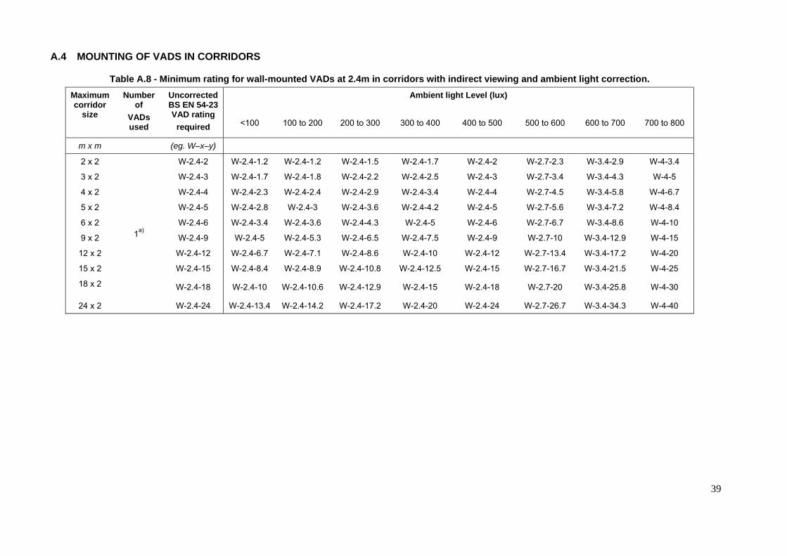
39
A.4 MOUNTING OF VADS IN CORRIDORS
Table A.8 - Minimum rating for wall-mounted VADs at 2.4m in corridors with indirect viewing and ambient light correction. Maximum corridor
size
Number of
VADs used
Uncorrected BS EN 54-23 VAD rating
required
Ambient light Level (lux)
<100 100 to 200 200 to 300 300 to 400 400 to 500 500 to 600 600 to 700 700 to 800
m x m (eg. W–x–y)
2 x 2
1a)
W-2.4-2 W-2.4-1.2 W-2.4-1.2 W-2.4-1.5 W-2.4-1.7 W-2.4-2 W-2.7-2.3 W-3.4-2.9 W-4-3.4
3 x 2 W-2.4-3 W-2.4-1.7 W-2.4-1.8 W-2.4-2.2 W-2.4-2.5 W-2.4-3 W-2.7-3.4 W-3.4-4.3 W-4-5
4 x 2 W-2.4-4 W-2.4-2.3 W-2.4-2.4 W-2.4-2.9 W-2.4-3.4 W-2.4-4 W-2.7-4.5 W-3.4-5.8 W-4-6.7
5 x 2 W-2.4-5 W-2.4-2.8 W-2.4-3 W-2.4-3.6 W-2.4-4.2 W-2.4-5 W-2.7-5.6 W-3.4-7.2 W-4-8.4
6 x 2 W-2.4-6 W-2.4-3.4 W-2.4-3.6 W-2.4-4.3 W-2.4-5 W-2.4-6 W-2.7-6.7 W-3.4-8.6 W-4-10
9 x 2 W-2.4-9 W-2.4-5 W-2.4-5.3 W-2.4-6.5 W-2.4-7.5 W-2.4-9 W-2.7-10 W-3.4-12.9 W-4-15
12 x 2 W-2.4-12 W-2.4-6.7 W-2.4-7.1 W-2.4-8.6 W-2.4-10 W-2.4-12 W-2.7-13.4 W-3.4-17.2 W-4-20
15 x 2 W-2.4-15 W-2.4-8.4 W-2.4-8.9 W-2.4-10.8 W-2.4-12.5 W-2.4-15 W-2.7-16.7 W-3.4-21.5 W-4-25
18 x 2 W-2.4-18 W-2.4-10 W-2.4-10.6 W-2.4-12.9 W-2.4-15 W-2.4-18 W-2.7-20 W-3.4-25.8 W-4-30
24 x 2 W-2.4-24 W-2.4-13.4 W-2.4-14.2 W-2.4-17.2 W-2.4-20 W-2.4-24 W-2.7-26.7 W-3.4-34.3 W-4-40

40
Table A.8 (continued)- Minimum rating for wall-mounted VADs at 2.4m in corridors with indirect viewing and ambient light correction. Maximum corridor
size
Number of
VADs used
Uncorrected BS EN 54-23 VAD rating
required
Ambient light Level (lux)
<100 100 to 200 200 to 300 300 to 400 400 to 500 500 to 600 600 to 700 700 to 800
m x m (eg. W–x–y)
4 x 2.5
2b)
W-2.4-2 W-2.4-1.2 W-2.4-1.2 W-2.4-1.5 W-2.4-1.7 W-2.4-2 W-2.7-2.3 W-3.4-2.9 W-4-3.4
8 x 2.5 W-2.4-4 W-2.4-2.3 W-2.4-2.4 W-2.4-2.9 W-2.4-3.4 W-2.4-4 W-2.7-4.5 W-3.4-5.8 W-4-6.7
12 x 2.5 W-2.4-6 W-2.4-3.4 W-2.4-3.6 W-2.4-4.3 W-2.4-5 W-2.4-6 W-2.7-6.7 W-3.4-8.6 W-4-10
15 x 2.5 W-2.4-7.5 W-2.4-4.2 W-2.4-4.5 W-2.4-5.4 W-2.4-6.3 W-2.4-7.5 W-2.7-8.4 W-3.4-10.8 W-4-12.5
18 x 2.5 W-2.4-9 W-2.4-5 W-2.4-5.3 W-2.4-6.5 W-2.4-7.5 W-2.4-9 W-2.7-10 W-3.4-12.9 W-4-15
21 x 2.5 W-2.4-10.5 W-2.4-5.9 W-2.4-6.2 W-2.4-7.5 W-2.4-8.8 W-2.4-10.5 W-2.7-11.7 W-3.4-15 W-4-17.5
24 x 2.5 W-2.4-12 W-2.4-6.7 W-2.4-7.1 W-2.4-8.6 W-2.4-10 W-2.4-12 W-2.7-13.4 W-3.4-17.2 W-4-20
28 x 2.5 W-2.4-14 W-2.4-7.8 W-2.4-8.3 W-2.4-10 W-2.4-11.7 W-2.4-14 W-2.7-15.6 W-3.4-20 W-4-23.4
36 x 2.5 W-2.4-18 W-2.4-10 W-2.4-10.6 W-2.4-12.9 W-2.4-15 W-2.4-18 W-2.7-20 W-3.4-25.8 W-4-30
40 x 2.5 W-2.4-20 W-2.4-11.2 W-2.4-11.8 W-2.4-14.3 W-2.4-16.7 W-2.4-20 W-2.7-22.3 W-3.4-28.6 W-4-33.4
The following general rules should be applied when installing VADs in corridor: a) When using one VAD to cover a length of corridor, the VAD should be sited at the half-way distance, or at the centre of either end; b) When using two VADs per corridor, the devices should be each sited at a quarter of the corridor distance from both ends, or in the centre of
either end.
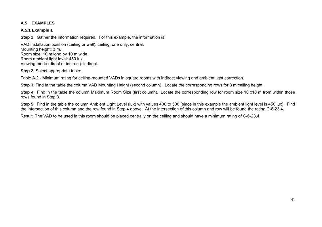
41
A.5 EXAMPLES A.5.1 Example 1 Step 1. Gather the information required. For this example, the information is:
VAD installation position (ceiling or wall): ceiling, one only, central. Mounting height: 3 m. Room size: 10 m long by 10 m wide. Room ambient light level: 450 lux. Viewing mode (direct or indirect): indirect.
Step 2. Select appropriate table:
Table A.2 - Minimum rating for ceiling-mounted VADs in square rooms with indirect viewing and ambient light correction.
Step 3. Find in the table the column VAD Mounting Height (second column). Locate the corresponding rows for 3 m ceiling height.
Step 4. Find in the table the column Maximum Room Size (first column). Locate the corresponding row for room size 10 x10 m from within those rows found in Step 3.
Step 5. Find in the table the column Ambient Light Level (lux) with values 400 to 500 (since in this example the ambient light level is 450 lux). Find the intersection of this column and the row found in Step 4 above. At the intersection of this column and row will be found the rating C-6-23.4.
Result: The VAD to be used in this room should be placed centrally on the ceiling and should have a minimum rating of C-6-23,4.

42
Table A.9 - Minimum rating for ceiling-mounted VADs in square rooms with indirect viewing and ambient light correction.
Maximum room size
VAD mounting
height
Uncorrected BS EN 54-23 VAD rating
required
Ambient light Level (lux)
<100 100 to 200 200 to 300 300 to 400 400 to 500 500 to 600 600 to 700 700 to 800
m x m m (e.g. C-x-y)
2 x 2
3
C-3-2.8 C-3-2.2 C-3-2.4 C-3-2.8 C-6-3.5 C-6-4.7 C-6-5.6 C-9-7 (O)-10-9.4
3 x 3 C-3-4.2 C-3-3.3 C-3-3.5 C-3-4.2 C-6-5.3 C-6-7 C-6-8.4 C-9-10.5 (O)-10-14
4 x 4 C-3-5.6 C-3-4.4 C-3-4.7 C-3-5.6 C-6-7 C-6-9.4 C-6-11.2 C-9-14 (O)-10-18.7
5 x 5 C-3-7 C-3-5.4 C-3-5.9 C-3-7 C-6-8.8 C-6-11.7 C-6-14 C-9-17.5 (O)-10-23.4
10 x 10 C-3-14 C-3-10.8 C-3-11.7 C-3-14 C-6-17.5 C-6-23.4 C-6-28 C-9-35 (O)-10-46.7
15 x 15 C-3-21 C-3-16.2 C-3-17.5 C-3-21 C-6-26.3 C-6-35 C-6-42 C-9-52.5 (O)-10-70

43
A.5.2 Example 2 Step 1. Gather the information required. For this example, the information is:
VAD installation position (ceiling or wall): Wall, two VADs, one at each end of the corridor. Mounting height: 2.4 m. Room size: 35 m long by 2.3 m wide. Room ambient light level: 300 lux. Viewing mode (direct or indirect): Direct.
Step 2. Select appropriate table:
Table A.7 - Minimum rating for wall-mounted VADs at 2.4m in corridors with direct viewing and ambient light correction.
Step 3. Find in the table the column which shows the number of VADs used in the room/corridor (second column). Locate the corresponding rows for two VADs
Step 4. Find in the table the column Maximum Room Size (first column). Locate the corresponding row for corridor size 35 m x 2.3 m from within those rows found in Step 3. In this example it is not an exact match, so the next highest size is 36 m x 2.5 m.
Step 5. Find in the table the column Ambient Light Level (lux) with values 200 to 300 (since in this example the ambient light level is 300 lux). Find the intersection of this column and the row found in Step 4 above. At this intersection the rating is shown as W-2.4-5.7.
Result: The VADs to be used in this corridor should be placed centrally at either end of the corridor and should have a minimum rating of W-2.4-5,7. The selection of central placement at either end allows for direct viewing by persons walking in either direction along the corridor. The VADs should not be obscured from direct sight at any point in the corridor, by, for example, items such as emergency exit signs, or decorative features.

44
Table A.10 - Minimum rating for wall-mounted VADs at 2.4m in corridors with direct viewing and ambient light correction.
Maximum corridor
size
Number of
VADs used
Uncorrected BS EN 54-23 VAD rating
required
Ambient light Level (lux)
<100 100 to 200 200 to 300 300 to 400 400 to 500 500 to 600 600 to 700 700 to 800
m x m (eg. W–x–y)
4 x 2.5
2b)
W-2.4-2 W-2.4-0.4 W-2.4-0.5 W-2.4-0.7 W-2.4-0.9 W-2.4-1.2 W-2.4-1.6 W-2.4-2 W-3.4-2.9
28 x 2.5 W-2.4-14 W-2.4-2.7 W-2.4-3.2 W-2.4-4.4 W-2.4-6.1 W-2.4-7.8 W-2.4-10.8 W-2.4-14 W-3.4-20
36 x 2.5 W-2.4-18 W-2.4-3.5 W-2.4-4.1 W-2.4-5.7 W-2.4-7.9 W-2.4-10 W-2.4-13.9 W-2.4-18 W-3.4-25.8
40 x 2.5 W-2.4-20 W-2.4-3.9 W-2.4-4.6 W-2.4-6.3 W-2.4-8.7 W-2.4-11.2 W-2.4-15.4 W-2.4-20 W-3.4-28.6
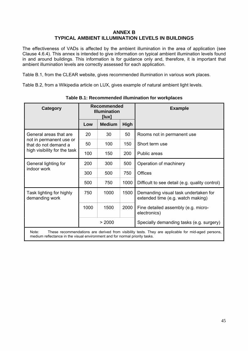
45
ANNEX B TYPICAL AMBIENT ILLUMINATION LEVELS IN BUILDINGS
The effectiveness of VADs is affected by the ambient illumination in the area of application (see Clause 4.6.4). This annex is intended to give information on typical ambient illumination levels found in and around buildings. This information is for guidance only and, therefore, it is important that ambient illumination levels are correctly assessed for each application.
Table B.1, from the CLEAR website, gives recommended illumination in various work places.
Table B.2, from a Wikipedia article on LUX, gives example of natural ambient light levels.
Table B.1: Recommended illumination for workplaces
Category Recommended Illumination
[lux]
Example
Low Medium High
General areas that are not in permanent use or that do not demand a high visibility for the task
20 30 50 Rooms not in permanent use
50 100 150 Short term use
100 150 200 Public areas
General lighting for indoor work
200 300 500 Operation of machinery
300 500 750 Offices
500 750 1000 Difficult to see detail (e.g. quality control)
Task lighting for highly demanding work
750 1000 1500 Demanding visual task undertaken for extended time (e.g. watch making)
1000 1500 2000 Fine detailed assembly (e.g. micro-electronics)
> 2000 Specially demanding tasks (e.g. surgery)
Note: These recommendations are derived from visibility tests. They are applicable for mid-aged persons, medium reflectance in the visual environment and for normal priority tasks.

46
Table B.2 - Examples of natural ambient lighting levels
Example Illumination (lux)
Moonless overcast night sky 0.0001
Moonless clear night sky with airglow 0.002
Full Moon on a clear night 0.27
Dark limit of civil twilight under a clear sky 3.4
Sunrise or sunset on a clear day. 400
Full daylight (not direct sun) 10,000-25,000
Direct sunlight on an average day 32,000 − 130,000
The outdoor light level is approximately 10,000 lux on a clear day. In buildings, in areas closest to windows, the light level may be reduced to approximately 1,000 lux although this could be significantly higher in the parts of the building that may be subjected to direct sunlight. Away from windows, the ambient light level may drop to as low as 25 to 50 lux unless it is compensated by additional lighting equipment. It is important that, in rooms which may be subjected to high level of natural external lighting, the highest lighting level expected should be considered when VADs are selected.
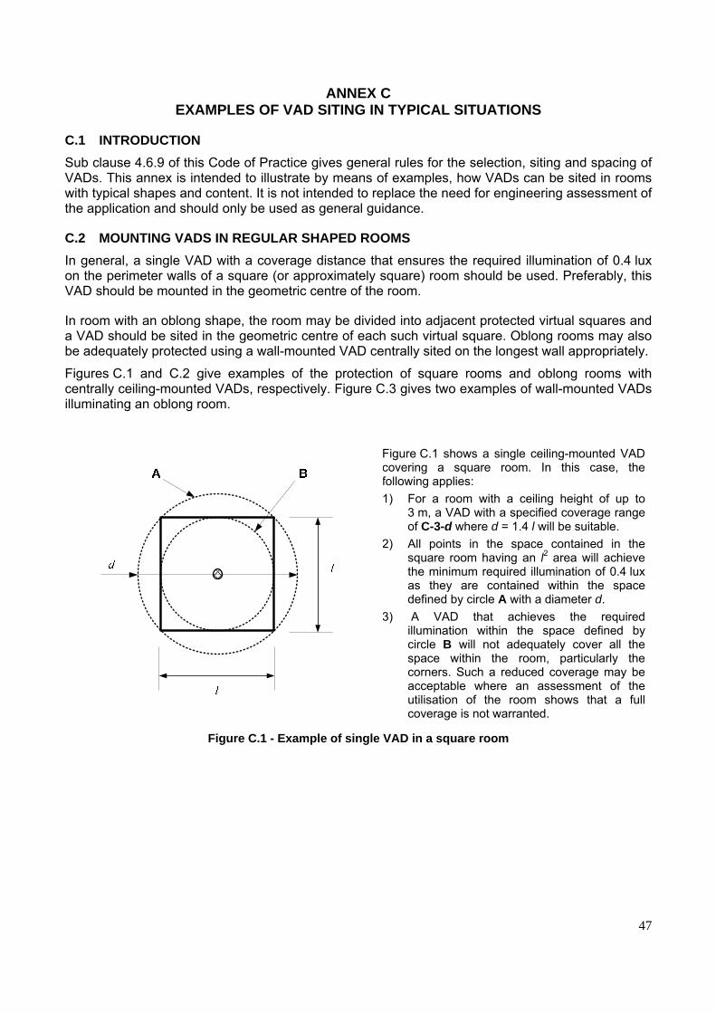
47
ANNEX C EXAMPLES OF VAD SITING IN TYPICAL SITUATIONS
C.1 INTRODUCTION Sub clause 4.6.9 of this Code of Practice gives general rules for the selection, siting and spacing of VADs. This annex is intended to illustrate by means of examples, how VADs can be sited in rooms with typical shapes and content. It is not intended to replace the need for engineering assessment of the application and should only be used as general guidance.
C.2 MOUNTING VADS IN REGULAR SHAPED ROOMS In general, a single VAD with a coverage distance that ensures the required illumination of 0.4 lux on the perimeter walls of a square (or approximately square) room should be used. Preferably, this VAD should be mounted in the geometric centre of the room.
In room with an oblong shape, the room may be divided into adjacent protected virtual squares and a VAD should be sited in the geometric centre of each such virtual square. Oblong rooms may also be adequately protected using a wall-mounted VAD centrally sited on the longest wall appropriately.
Figures C.1 and C.2 give examples of the protection of square rooms and oblong rooms with centrally ceiling-mounted VADs, respectively. Figure C.3 gives two examples of wall-mounted VADs illuminating an oblong room.
Figure C.1 shows a single ceiling-mounted VAD covering a square room. In this case, the following applies: 1) For a room with a ceiling height of up to
3 m, a VAD with a specified coverage range of C-3-d where d = 1.4 l will be suitable.
2) All points in the space contained in the square room having an l2 area will achieve the minimum required illumination of 0.4 lux as they are contained within the space defined by circle A with a diameter d.
3) A VAD that achieves the required illumination within the space defined by circle B will not adequately cover all the space within the room, particularly the corners. Such a reduced coverage may be acceptable where an assessment of the utilisation of the room shows that a full coverage is not warranted.
Figure C.1 - Example of single VAD in a square room

48
C.3 MOUNTING VADS IN L-SHAPED ROOMS An L-shaped room can be covered by a single wall-mounted VAD as shown in Figure C.4a.
Figure C.2 shows two ceiling-mounted VADs covering an oblong room, of dimensions l x w, by dividing the room in virtual squares. In this case, the following applies: 1) A VAD with a specified coverage
range of C-3-d where d = 1.4 w will be suitable.
2) Where the length does not contain an exact number of widths, a number of overlapping virtual squares may need to be used in calculating coverage.
3) A reduction of the coverage to less than 0.4 lux may be acceptable where an assessment of the utilisation of the room shows that a full coverage is not warranted.
Figure C.2 - Example of two ceiling-mounted VADs in an oblong room
Figure C.3a shows how an oblong room of dimensions l x w can be covered with two VADs. Figure C.2.3a gives an example of a room where the width, w, is less than half the length, l. Figure C.3b gives an example of a room where the width, w, is greater than half the length, l. In these cases, the following applies:
1) 2 x VADs preferably mounted on opposite walls and with a specified coverage range of l/2 x l/2 will be suitable where the width is less than the length of the room; and
2) 2 x VADs preferably mounted at the ¼ distance of the longest wall and on opposite side.
NOTE 1 Mounted VADs on opposite walls is best to ensure that one or the other are most likely to be in the field of view of the occupants of the room.
NOTE 2 In Figure C.3b, the positioning of the VADs provides a coverage overlap in the centre of the room.
Figure C.3 - Examples of two wall-mounted VADs in an oblong room

49
Alternatively, L-shaped space can be covered by several ceiling-mounted VADs as shown in Figure C.4b.
Figure C,4 shows how wall- mounted VADs can be used to cover an L-shaped room of length l, minimum width w1 and maximum width w2.
Figure C.4a shows a single wall-mounted VAD with a coverage distance of W-h-l were h is the maximum height at which the device is mounted and l is the width in metres of the cuboid which contain the L-shaped space. NOTE All points in the L-shaped room will achieve the minimum required illumination of 0.4 lux as they are contained within the space defined by the maximum coverage distance of the VAD, i.e. l.
Figure C.4b shows how three wall-mounted VADs with smaller coverage distances can be used to cover the same L-shaped room as in Figure C.4a by subdividing the room in a number of square areas. In this example, assuming that w1 is greater than l/2 and w3 is greater than l3, three VADs may be used as follows:
• 2 x W-h-w1
• 1 x W-h-w3 NOTE Figure C.4b also demonstrate how, by placing VADs on opposite walls, all occupants of the room can be in direct view of one of, at least, one of the VADs.
Figure C.4 - Example of wall-mounted VADs in an L-shaped room
Figure C.5 shows how the L-shaped room illustrated in Figure C.3 can be sub-divided in a number of square spaces and covered by a several ceiling VADs mounted in the centre of each virtual space and having adequate coverage distance, i.e. d1 or d2. NOTE In practice, one device type capable of covering the worst case distance would be used in all positions.
Figure C.5 - Example of several ceiling-mounted VADs in an L-shaped room
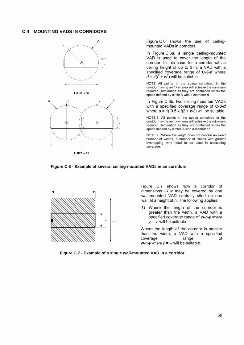
50
C.4 MOUNTING VADS IN CORRIDORS
Figure C.6 shows the use of ceiling-mounted VADs in corridors.
In Figure C.6a, a single ceiling-mounted VAD is used to cover the length of the corridor. In this case, for a corridor with a ceiling height of up to 3 m, a VAD with a specified coverage range of C-3-d where d = √(l2 + w2) will be suitable. NOTE All points in the space contained in the corridor having an l x w area will achieve the minimum required illumination as they are contained within the space defined by circle A with a diameter d.
In Figure C.6b, two ceiling-mounted VADs with a specified coverage range of C-3-d where d = √((0.5 x l)2 + w2) will be suitable. NOTE 1 All points in the space contained in the corridor having an l x w area will achieve the minimum required illumination as they are contained within the space defined by circles A with a diameter d.
NOTE 2 Where the length does not contain an exact number of widths, a number of circles with greater overlapping may need to be used in calculating coverage.
Figure C.6 - Example of several ceiling-mounted VADs in an corridors
Figure C.7 shows how a corridor of dimensions l x w may be covered by one wall-mounted VAD centrally sited on one wall at a height of h. The following applies:
1) Where the length of the corridor is greater than the width, a VAD with a specified coverage range of W-h-y where y = l will be suitable.
Where the length of the corridor is smaller than the width, a VAD with a specified coverage range of W-h-y where y = w will be suitable.
Figure C.7 - Example of a single wall-mounted VAD in a corridor
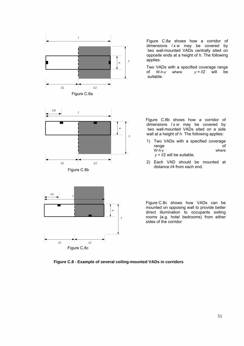
51
l
l/2 l/2
w
y
l/4
Figure C.8c
l
l/2 l/2
w
y
l/4
Figure C.8b
l
l/2 l/2
w y
Figure C.8a
Figure C.8a shows how a corridor of dimensions l x w may be covered by two wall-mounted VADs centrally sited on opposite ends at a height of h. The following applies:
Two VADs with a specified coverage range of W-h-y where y = l/2 will be suitable.
Figure C.8b shows how a corridor of dimensions l x w may be covered by two wall-mounted VADs sited on a side wall at a height of h. The following applies:
1) Two VADs with a specified coverage range of W-h-y where y = l/2 will be suitable.
2) Each VAD should be mounted at distance l/4 from each end.
Figure C.8c shows how VADs can be mounted on opposing wall to provide better direct illumination to occupants exiting rooms (e.g. hotel bedrooms) from either sides of the corridor
Figure C.8 - Example of several ceiling-mounted VADs in corridors
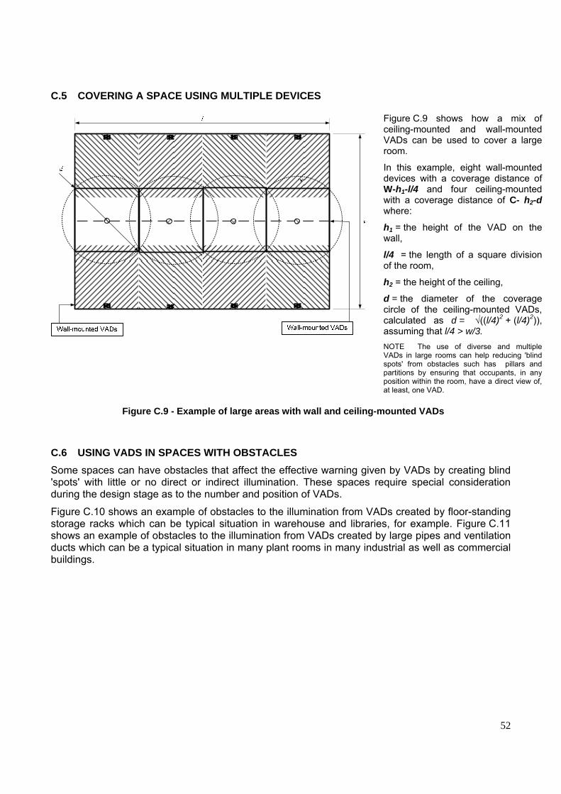
52
C.5 COVERING A SPACE USING MULTIPLE DEVICES
Figure C.9 shows how a mix of ceiling-mounted and wall-mounted VADs can be used to cover a large room.
In this example, eight wall-mounted devices with a coverage distance of W-h1-l/4 and four ceiling-mounted with a coverage distance of C- h2-d where:
h1 = the height of the VAD on the wall,
l/4 = the length of a square division of the room, h2 = the height of the ceiling,
d = the diameter of the coverage circle of the ceiling-mounted VADs, calculated as d = √((l/4)2 + (l/4)2)), assuming that l/4 > w/3. NOTE The use of diverse and multiple VADs in large rooms can help reducing 'blind spots' from obstacles such has pillars and partitions by ensuring that occupants, in any position within the room, have a direct view of, at least, one VAD.
Figure C.9 - Example of large areas with wall and ceiling-mounted VADs
C.6 USING VADS IN SPACES WITH OBSTACLES Some spaces can have obstacles that affect the effective warning given by VADs by creating blind 'spots' with little or no direct or indirect illumination. These spaces require special consideration during the design stage as to the number and position of VADs.
Figure C.10 shows an example of obstacles to the illumination from VADs created by floor-standing storage racks which can be typical situation in warehouse and libraries, for example. Figure C.11 shows an example of obstacles to the illumination from VADs created by large pipes and ventilation ducts which can be a typical situation in many plant rooms in many industrial as well as commercial buildings.

53
In spaces with storage racks, the racks and associated shelving can potentially mask VADs from occupants in the space between the racks. Figure C.10 shows an example of an area of a room with a number of racks. The area is equipped with two ceiling-mounted VADs. Occupants in A areas are in spaces directly illuminated by one of the VADs while there is no direct illumination from either VAD in B areas. In such cases, care should be taken that:
or both of the following should be applied:
1) sufficient numbers of VADs are installed such that any persons within the space between racks have a direct view of, at least, one VAD;
2) the VADs installed provide sufficient illumination of the storage rack surfaces to ensure adequate warning of occupants who do not have direct view of the, at least, one VAD.
Figure C.10 - Example of VADs in space with floor standing storage racks
AAB B
Duct
Supply pipes
b
In plant rooms, supply pipes and ducts (e.g. ventilation ducts) can often mask VADs from occupants of the room, with potentially adverse effect on the effectiveness of the warning given to them. Figure C.11 shows an example of a room with ventilation duct, ceiling suspended and wall-mounted supply pipes. The room is furnished with one wall-mounted VAD and one ceiling-mounted VAD. Occupants in A areas are in spaces illuminated by one or more VADs while both VADs are masked from the occupants in the B areas. In such cases, care should be taken that:
1) sufficient numbers of VADs are installed such that the occupied areas of the room are adequately illuminated, and/or
2) the VADs installed provide adequate illumination of surfaces that are adjacent to occupants of the room where those occupants do not have a direct view of, at least, one VAD.
Figure C.11 - Example of VADs in plant rooms with pipes and ventilation ducts


