23
Page 1 Lotus Europa 2037R Wiring August 25, 2012 Updated January 15, 2018. europawire2018.odg
| Date post: | 06-Feb-2018 |
| Category: |
Documents |
| Upload: | truongmien |
| View: | 231 times |
| Download: | 0 times |

Page 1
Lotus Europa 2037R Wiring
August 25, 2012Updated January 15, 2018.
europawire2018.odg
Horn
Radiator Fan BlackBox
Fuses
MegaSquirtFuel/Water Fuses
Knock Sense control
Fuel Pump
Alternator
Ignition Coils
ThermostatEmergencyElectrical
On/Off
Engine coolantWater pump,Davies Craig
EWP 80
LC-1 controller
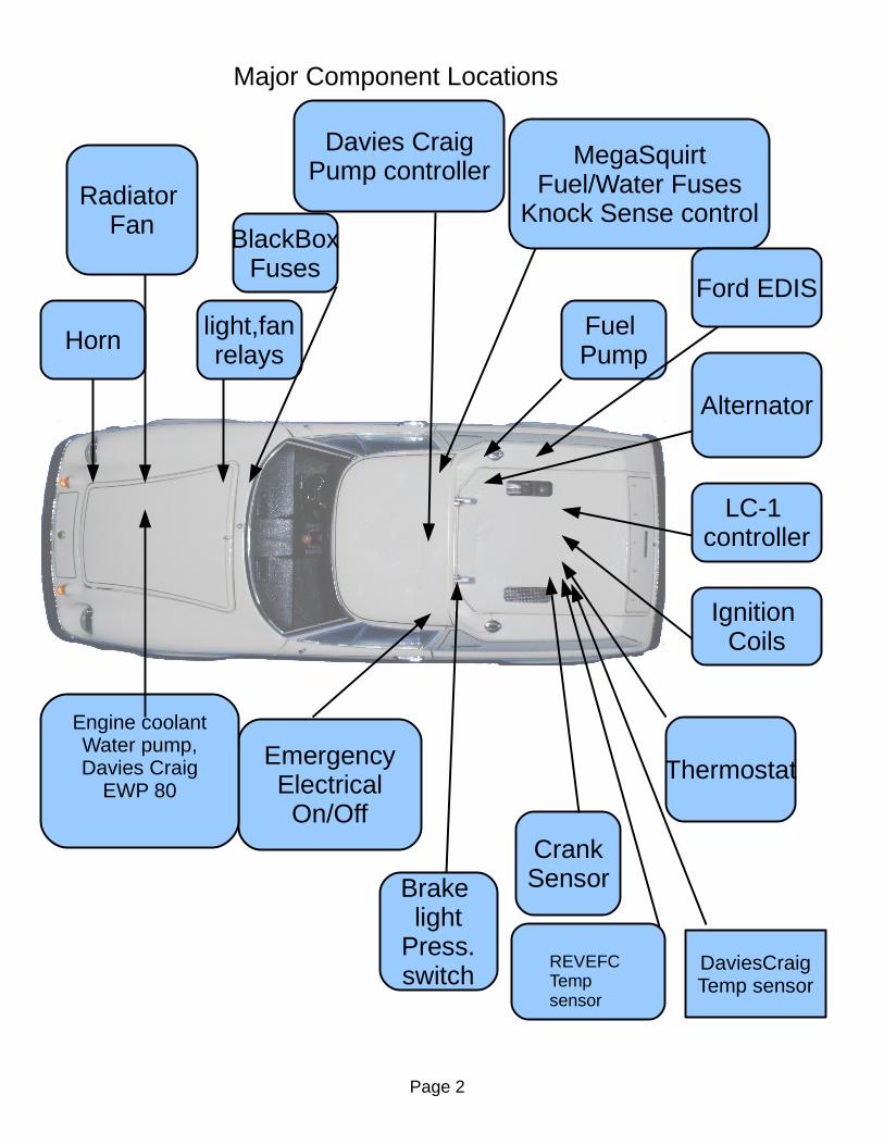
Major Component Locations
CrankSensor
light,fanrelays
Ford EDIS
DaviesCraigTemp sensor
REVEFCTemp sensor
Davies CraigPump controller
Brake light
Press.switch
Page 2

The BlackBox fuse panel (abbreviated here as BB) is from Enos Custom Components, EnosCustom.com. The LC-1 is by Innovate and It interfaces between the wide-band air/fuel(lambda) sensorAnd Megasquirt.
Much of the wire is labeled every 4 inches and comes from Enos Custom Components. Some of the wire is ordinary auto store wire but has labels I attached at each end. None of the wire follows British color coding standards. Nearly all of the wire is rather larger than Lotus standard automotive usage!.
Unfortunately some of the Enos wires such as Horn Switch are black (though labeled every 4 inches). In addition wires to an external-power-socket near the BlackBox (to drive a phone charger or GPS device) are black. Really only ground wires should be black.
Page 3

Here is the BlackBox in the passenger footwell – with the cover removed. The two large red wires with the big screw are power from the battery and from the blackbox to the ignition key. So the big red wires are hot (unless the battery disconnect switch is turned to off). The single large yellow wire comes from the ignition key and it is hot when the ignition key is turned as far as the accessory position.
44
Page 4
The square relay is the Horn relay. Of the two round flasher tins the left one is the hazard flasher and the right is the turn signal flasher. The horizontal orange wire replaces a resistor as the ignition runs at a full 12 volts not the 6 volts used on many older cars (we use electronics here).
On other pages the black box is generally indicated by a rectangular square with the wordsBlack Box at the top and the Block positions hinted at. See Page 5 for the actual Black BoxConnection positions, .
5
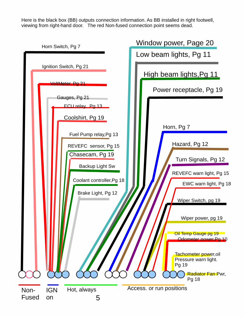
Here is the black box (BB) outputs connection information. As BB installed in right footwell, viewing from right-hand door. The red Non-fused connection point seems dead.
Radiator Fan Pwr,Pg 18
Tachometer power,oilPressure warn light. Pg 19
Odometer power,Pg 10
Wiper Switch, pg 19
Wiper power, pg 19
Turn Signals, Pg 12
Hazard, Pg 12
Horn, Pg 7
Power receptacle, Pg 19
High beam lights,Pg 11
Low beam lights, Pg 11
Window power, Page 20
Brake Light, Pg 12
Fuel Pump relay,Pg 13
Backup Light Sw
Gauges, Pg 21
VoltMeter, Pg 21
Horn Switch, Pg 7
Ignition Switch, Pg 21
Non-Fused
IGN on
Hot, always Access. or run positions
Oil Temp Gauge pg 19
Coolant controller,Pg 18
Coolshirt, Pg 19
Chasecam, Pg 19
REVEFC sensor, Pg 15
REVEFC warn light, Pg 15
EWC warn light, Pg 18
ECU relay, Pg 13

This indicates the major wiring positions. Black here are The major ground wires. Red is the main bundle of wiresFrom the dash and black-box. Green is wires between engine and Megasquirt. Blue is some wires for engine management. Various wire groups (lights, for example) are not shown here.
6

7
The HornSwitch position on Black Box runs to theHorn button then to ground.
Horn switch Position onBlack Box
Horn ButtonOn Dash Ground
Horn
Ground
Horn in frontOf radiator
Black Box provides the relayAnd fuse for the horn.
Black Box
HornSwitch
HazardFlashwarning
Voltmeter
Oil Pressure
Coolant Temp
Fuel Level
Oil TempGauge Hazard
switch
Fan Not connected
RH window motor
LH window motor
Headlightswitch
Horn button
Fuel Pumpswitch
Wiper Switch
SpeedometerCalibrationbutton
Small red light EWPControllererror
KnockSensorLight
Big Red LightREVEFCSense coolanthot
Red LightNot connected
Ash tray notInstalled as it
Rattles!
88
8

Tachometer,Voltage pulsesensing
HeadlightHigh BeamOn/off
TPI-TechElectronic speedometer
DirectionalSignal(blinks)
Oil PressureLow ifon
The TPI (aka Daytona) speedometer is just slightly larger diameter than theStock instrument. Recalibration is a bit fiddly as there is just a single button,(see previous page for location), but it is only needed if changing tire size. The light inside the Speedo is a bit dim and the digits are a bit small.
9

10
Black BoxOdometer Power
Speedometer Back,Connector sizeexaggerated
SpeedSensorGround
Odo light powerSwitched with lights
Speedo Calibrationpushbutton
Speed SenseTransaxleRear end
White speedSense wireShown yellow
Lights, page 11, LS

11
Lights circuits are complicated. This is this begins the power side. The power is from black box 'alarm cig lighter' which is always hot. Three wires out. Dark Gray (labeled low beam). Two greens labeled High Beam. Relays ensure only low power goes through switches.
Footwell Hibeam
relay
FootwellLobeamRelay
BehindDash:
Lights RelayDash:LightsSwitch
InstrumentLights
Tail Lights, Lic PlateLightsRunning lights
LS ref From Pg 10:Speedo light
Headlight
Headlight
BlackboxAlarmCigLtr
SteeringColumn:Hi LoBeam Switch
High Beam
Low Beam

12
Lt Gray really white
Green/white Output wire
Green/RedOutput wire
A pair of xor circuits, one per side, would fix the brake-lightOverriding turn signal issue.
TurnSignal
Hazard
Brake Lt
Black Box:
LeftFront
Turnsig
RightRear
Turnsig
LeftRear
Turnsig
RightFront
Turnsig
Brake SwitchIn Engine
compartment
HazardSwitch
DashGreen Turn
SigLight
The diodes prevent the brake wires from connecting left and right turn signals. A defect is that If brakes pressed both rears light, no rear turnsignal while brakes pressed. Colors to the diodesAnd wires to the turn signal light were hard to determine (oops).
Steering Col:Turn SignalSwitch
Right Turn
Left Turn
Diodes under dash Near (under) left end ofradio slot.

Page 13
Battery
ECU
FuelRelay
ECURelay Power
Fusepanel
FuelPump
Knocksensor
KnockSense
controller
FuelPumpswitch
InertialFuel
Pumpcutoff
EDIS
Tacho-meter
Dashboard and pass. footwell
Behind passenger seat
Engine Compartment
ECUrelay
FuelPumpRelay
BlackBox
Injector1,4
Injector2,3
LC-1Lambdamodule
For rpmdisplay
KnockSenseDashlight
ToEWPPg 18
ECU wiringFuses near Power Fuse panelNot shown
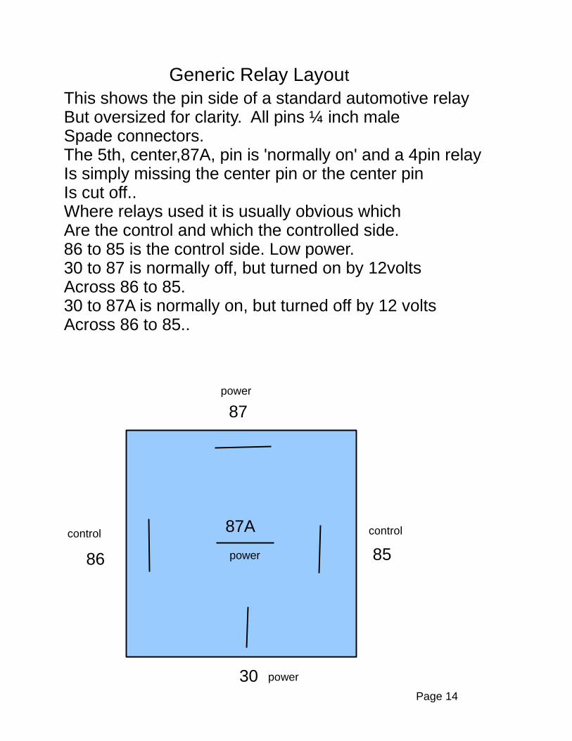
Generic Relay LayoutThis shows the pin side of a standard automotive relayBut oversized for clarity. All pins ¼ inch maleSpade connectors.The 5th, center,87A, pin is 'normally on' and a 4pin relayIs simply missing the center pin or the center pinIs cut off..Where relays used it is usually obvious whichAre the control and which the controlled side.86 to 85 is the control side. Low power.30 to 87 is normally off, but turned on by 12voltsAcross 86 to 85.30 to 87A is normally on, but turned off by 12 voltsAcross 86 to 85..
8586
87
30
87Acontrol control
power
power
power
Page 14
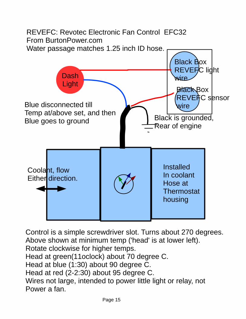
REVEFC: Revotec Electronic Fan Control EFC32From BurtonPower.com Water passage matches 1.25 inch ID hose.
Black BoxREVEFC sensorwire
Black is grounded,Rear of engine
Blue disconnected tillTemp at/above set, and thenBlue goes to ground
Control is a simple screwdriver slot. Turns about 270 degrees.Above shown at minimum temp ('head' is at lower left).Rotate clockwise for higher temps.Head at green(11oclock) about 70 degree C.Head at blue (1:30) about 90 degree C.Head at red (2-2:30) about 95 degree C.Wires not large, intended to power little light or relay, notPower a fan.
Coolant, flowEither direction.
DashLight
InstalledIn coolantHose atThermostat housing
Black BoxREVEFC lightwire
Page 15

Page 16
1
FordCoilPack
EDIS wiringFord EDIS-4 module is on right side of engine bay between oil filter and fuel filter. Wires for connectors 1,3,5,and 6 are shielded and the shields grounded through connector 7. It is tricky to avoid accidentally grounding the wrong thing. But the EDIS is tough and will survive wiring errors. Physical location of the crank sensor pickup is critical. 20-50 thousandths of an inch from the end of the pickup to the flywheell pins. Use Megatune logging to diagnose errors.View is looking into wiring harness connector.. PIP and SAW are signals between Megasquirt and EDIS. See Megasquirt documentation. As installed, #1 is at the bottom., #12 at the top.
VR Sensor,
At flywheel
1
2
3
Coil PackConnector
4
2
5
6
7
8
9
10
11
12
3
shieldshieldIgn+
PowerFuse panel
Pg 13
Plug in
Neg Pos
PIP: to DB37 pin24
SAW: to DB37 pin 36
To Tachometer
25uFcapacitor
Bottom
Top

Innovate LC-1 wiring
Innovate LC-1 acts as the intermediary between the exhaust gasses (via a bung in the exhaust) and Megasquirt. It plugs into power, the ECU, and of course the Bosch wide-band exhaust sensor. Never run the engine with the Bosch sensor in the exhaust unless the LC-1 is powered,An unpowered sensor will be destroyed.
Innovate LC-1Attached to frame near starter
BoschSensorPlugsIn here
PowerECU relay
Pg 13
The wires (shown right side here) are in a cable that goes to the ECU location inThe passenger compartment. The yellow wire is useless.The brown is the signal that Megasquirt wants for the exhaust gas.
Yellow notconnected
Red is red LED behind passenger seat. Slow steady blinkMeans warming up. On and unblinking means operatingNormally. Pulses followed by off (and repeating) meansError condition, see LC-1 manual.
Momentary switch is right by LED, push this whileSensor is unscrewed from BUNG in exhaust to doA free air calibration. See LC-1 manual.
Page 17
To ECUGas sense
Pg 13
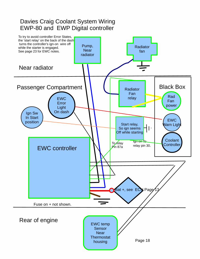
Davies Craig Coolant System WiringEWP-80 and EWP Digital controller
Pump,Near
radiator
Radiatorfan
EWC controller
EWC tempSensorNear
Thermostathousing
RadFan
power
RadiatorFanrelay
Black Box
Near radiator
Passenger Compartment
Rear of engine
Bat +, see ECU Page 13
EWCErrorLight
On dash
CoolantController
Ign on To relay pin 30.
Fuse on + not shown.
Page 18
EWCWarn LightStart relay,
So ign seemsOff while starting
Ign SwIn Startposition
To relayPin 87a
To try to avoid controller Error States,the 'start relay' on the back of the dash turns the controller's ign-on wire off while the starter is engaged.See page 23 for EWC notes.

Miscellaneous Circuits
Black Box
TachometerPower, oil
Press. warn
OilTemp
Gauge
WiperSwitch
andPower
PowerReceptacle
Chasecam
TachometerOil Press
Warn
Press. Sw.On frame By engine
Oil TempGauge
On dash
Oil TempSender
On Oil FilterHsg
White wire
WiperSwitchWiper
Connector1
2
3
4
5 4
3
21
RLG Red Lt Grn
ULG blue lt grn
NLG brown lt grn
Standard automotivePower
recepticle
ChaseCamrecorder
WeatherPackconnector
Page19
CoolshirtCoolshirtSystempump
WeatherPackconnector
Pump Speed
controller
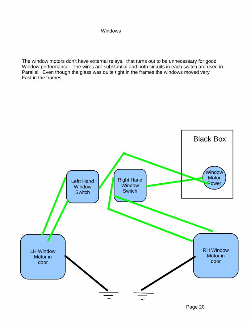
Windows
The window motors don't have external relays, that turns out to be unnecessary for goodWindow performance. The wires are substantial and both circuits in each switch are used inParallel. Even though the glass was quite tight in the frames the windows moved veryFast in the frames..
Black Box
WindowMotorPower
Right HandWindowSwitch
Leftt HandWindowSwitch
RH WindowMotor in
door
LH WindowMotor in
door
Page 20

Page 21
Gauges, Voltmeter
Black Box
Gauges
Voltmeter
Voltage converter
Gauge and voltmeter circuits are all between the black box and the gauges on the dash.
The actual VoltmeterOn dash
Fuel gaugeOn dash
Water TempGauge on
dash
Water TempSender onThermostat
Housing
Fuel sensorNot
connected
10 volts here
White gauge power wires here all labeled “gauge” on the wire itself.
white
Brown wireLabeled“fuel gauge”
Key Switch toStart engine
Solenoid onStartermotor
1 start
2 battery power
3 Ign. on.
5 Accessory on
IgnitionSwitch
When on at switchTells Black Box Ignition is on.
ACCESS12Volts
AtStarter
To EWCController
Relay,Pg 18
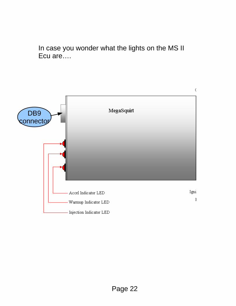
In case you wonder what the lights on the MS IIEcu are….
DB9connector
Page 22
Page 23
EWC Controller notes: If the engine is cold and the EWC is powered the EWC will goInto an error condition after a couple minutes, flashing lights. EWC expects the temperatures to get above 86 degrees F within the initial couple of minutes. See the EWC book for additional error conditions.


