26
2011‐02‐23 1 Filter Box Operating and Service Manual.doc Operating and Service Manual Front End Electronics Crate Low Voltage Power Supply Filter Filter Box Revision – D

2011‐02‐23
1 Filter Box Operating and Service Manual.doc
Operating and Service Manual
Front End Electronics Crate
Low Voltage Power Supply Filter
Filter Box Revision – D

2011‐02‐23
2 Filter Box Operating and Service Manual.doc
TABLE OF CONTENTS
Contents SPECIFICATION ........................................................................................................................................................................ 5
Monitor Port ........................................................................................................................................................................... 7
Input Output Terminals ........................................................................................................................................................... 8
THEORY of OPERATION ......................................................................................................................................................... 10
Filter Frequency Response .................................................................................................................................................... 12
Assembly Notes: .................................................................................................................................................................... 13
Primary Shield/Cover Removal ............................................................................................................................................. 13
Primary Shield/Cover Replacement ...................................................................................................................................... 13
PCB Assembly ........................................................................................................................................................................ 14
Schematic .............................................................................................................................................................................. 15
Single Filter Section ............................................................................................................................................................... 16
Mechanical Drawings ............................................................................................................................................................ 24
Bill Of Materials ..................................................................................................................................................................... 25
APPENDIX .............................................................................................................................................................................. 26
Title Document # ............................................................................................................................................................... 26
Figure 1: Filter Box with Primary Shield removed .................................................................................................................. 3
Figure 2: Filter with Primary Cover Installed .......................................................................................................................... 4
Figure 3 Filter Box Monitor Port Pinout .................................................................................................................................. 7
Figure 4 Filter Box PCB Top ..................................................................................................................................................... 8
Figure 5 Vicor OUT to Filter IN ................................................................................................................................................ 8
Figure 6 Filter Box OUT to Analog Backplane with G10 Cover installed ................................................................................. 9
Figure 7: Single Filter Schematic ........................................................................................................................................... 10
Figure 8: Typical Ripple reduction with current increase. .................................................................................................... 11
Figure 9: Attenuation ............................................................................................................................................................ 12
2011‐02‐23
3 Filter Box Operating and Service Manual.doc
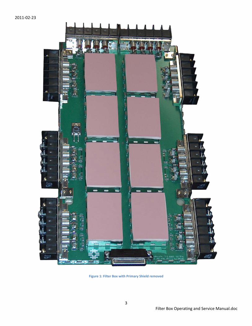
Figure 1: Filter Box with Primary Shield removed

2011‐02‐23
4 Filter Box Operating and Service Manual.doc
Figure 2: Filter with Primary Cover Installed

2011‐02‐23
5 Filter Box Operating and Service Manual.doc
SPECIFICATION
• Eight (8) Independent channels
• Voltage Rating 100V
• Current Rating 15A
• Resistance (each leg) 13 to 19 milliOhms
• Attenuation Common & Differential Modes45db/decade starting at 30KHz
• Monitor Port 2.00V @ Normal Operating Levels
o 8 Analog Channels
o 1 Over Temperature Switch

2011‐02‐23
6 Filter Box Operating and Service Manual.doc
o GENERAL INFORMATION
The Filter Box is designed to be part of the Low Voltage Power Supply for the Front End Electronics (FEE) and Heater Crates. The filter removes most of the switching noise produced by the commercial Vicor power supply. The Filter Box also provides a voltage monitor port and over temperature signal for the Internal Crate Controller (ICC). The over temperature switch closes a 60°C.
The FEE crates require eight (8) voltage rails, two for digital and six for analog circuitry. The Heater crates require four (4) rails, two for control circuits and two for power circuits. Each rail has its own filter and each filter is electrically identical.
The filter uses feed‐through capacitors for input and output connections to the main box. The main box is a Faraday shield. The top, bottom and center layers of the circuit board will act as EMI shields and will be connected to chassis ground. Each filter section or channel within the box has individual shields. The box dimensions are approximately 12”x6”x0.75”. The box is mounted directly to the Vicor power supply. The outputs of the Vicor connect directly to the inputs of the filter box. The output of the Filter Box connects directly to the Analog Backplane that distributes power to the Front‐End Electronics Transition cards.
The filter is a differential /common mode filter and all components are rated to handle a minimum of 15 Amps continuous.
Thermal management is handled by conduction from components to the PCB, then from secondary shield through thermal pad to the primary shields attached to the Vicor chassis.
PCB Details:
• The PCB will require a minimum of 8 layers. Power plane layer require 2 ounce copper while all other layers can be 1 ounce.
• The PC board itself will act as one side of the EMI chassis of the Filter Box. • All electrical connections into and out of the Filter Box are made through filtered barrier strips. • Power planes will transfer the voltages to and from the individual filters. • Inputs (noisy) to and Outputs (quiet) from the filter box will be separated by the center ground plane.

2011‐02‐23
7 Filter Box Operating and Service Manual.doc
Monitor Port This port provides a way to monitor the output voltages of the Filter Box. The signals are current limited and scaled such that at normal operating voltages the output is 2.00 volts.
Figure 3 Filter Box Monitor Port Pinout
+++
+
+
++
+
++
Blue ovals indicate Heater Monitoring
Red ovals indicate Front End Electronics Monitoring

2011‐02‐23
8 Filter Box Operating and Service Manual.doc
Input Output Terminals The Filter Box is installed on the Vicor supply so the terminals on the end are above the supply terminals. We are trying to make the wiring short in length.
Figure 4 Filter Box PCB Top
Figure 5 Vicor OUT to Filter IN

2011‐02‐23
9 Filter Box Operating and Service Manual.doc
Figure 6 Filter Box OUT to Analog Backplane with G10 Cover installed

2011‐02‐23
10 Filter Box Operating and Service Manual.doc
THEORY of OPERATION Several conditions require the use of switching power supplies in the DECam project. The primary restriction is the limited space available. Switching supplies are however inherently noisy and cannot be uses with sensitive electronics without removing as much switching noise as possible.
The filter box uses a standard differential and common mode filter arrangement. The lowest current component can handle a maximum current of 19Amps.
Figure 7: Single Filter Schematic
Measurements show that the Vicor supply produces larger amounts of common‐mode noise than differential‐mode noise. The filter addresses both issues.
The filter box is a six sided enclosure that forms a Faraday shield. The box is electrically tied to the Vicor chassis allowing the common mode noise to return to the source (Vicor outputs) as quickly as possible. Inputs to the box are minimum length twisted pairs. Output lengths are also minimized going directly to the Analog Backplane.
Each output from the Vicor is isolated until it reaches the Analog backplane. There all the returns are connected together and through a large braid tied to the FEE crate chassis. This is our single point star connection. Any other connections of the power rails will form a ground loop and must be avoided.
The common mode choke inside the filter must have current flowing to work properly. In fact the more current that flows the better the filter works. There is a tradeoff between the maximum current and the inductance of the choke.
Figure 8 shows a typical reduction in noise ripple from no current on the top trace to 5 Amps on the bottom trace in 1 Amp steps.

2011‐02‐23
11 Filter Box Operating and Service Manual.doc
Figure 8: Typical Ripple reduction with current increase.

2011‐02‐23
12 Filter Box Operating and Service Manual.doc
Filter Frequency Response
Figure 9: Attenuation

2011‐02‐23
13 Filter Box Operating and Service Manual.doc
Assembly Notes: There are a few procedures that must be preformed to yield a box that will fit properly into the final FEE crate.
Primary Shield/Cover Removal The primary shield and PCB are held together by 16 brass screws, two on each of the terminal blocks. These screws sandwich the shield between the terminal block and its mounting bracket. The Primary shield has slotted holes so they only need to be loosened to remove the cover. There is also two nuts on the subminiature ‘D’ connector that need to be removed before the shield can be separated from the PCB. At this point the shield will be held by the EMI fence on the monitor end (‘D’ sub) and in the space on each side. It is best to pry the cover off with a screwdriver to avoid bending it or the fencing.
Primary Shield/Cover Replacement Assembling the Primary shield/cover requires some adjustments to ensure proper fit with the mounting brackets. The thermal pads on the Secondary shields press against the Primary shield and must be compressed slightly during assembly. The Primary shield is first attached to the Vicor top. Next the PCB is carefully positioned so all the fingers on each EMI fence engage before seating the four mounting bracket stops to contact the cover.

2011‐02‐23
14 Filter Box Operating and Service Manual.doc
PCB Assembly

2011‐02‐23
15 Filter Box Operating and Service Manual.doc
Schematic

2011‐02‐23
16 Filter Box Operating and Service Manual.doc
Single Filter Section

2011‐02‐23
17 Filter Box Operating and Service Manual.doc
Data Sheets

2011‐02‐23
18 Filter Box Operating and Service Manual.doc

2011‐02‐23
19 Filter Box Operating and Service Manual.doc

2011‐02‐23
20 Filter Box Operating and Service Manual.doc

2011‐02‐23
21 Filter Box Operating and Service Manual.doc

2011‐02‐23
22 Filter Box Operating and Service Manual.doc

2011‐02‐23
23 Filter Box Operating and Service Manual.doc

2011‐02‐23
24 Filter Box Operating and Service Manual.doc
Mechanical Drawings
DES FRONT END DC FILTER BOX SCHEMATIC/PCB ED‐173687‐1/2
DES FRONT END DC FILTER BOX ASSEMBLY MD‐173688‐A
DES FRONT END DC FILTER BOX PRIMARY EMI SHIELD MD‐173689‐D
DES FRONT END DC FILTER BOX EMI 1.5IN 3‐PIN FENCE MD‐173690‐1
DES FRONT END DC FILTER BOX EMI 2.25IN 4‐PIN FENCE MD‐173691‐1
DES FRONT END DC FILTER BOX EMI 2.25IN 5‐PIN FENCE MD‐173691‐2
DES FRONT END DC FILTER BOX BARRIER STRIP BRACKET MD‐173692‐D
DES FRONT END DC FILTER BOX PCB MOUNTING BRACKET MD‐173693‐D
DECAM FRONT END ELECTRONICS FITLER BOX G10 INSULATOR MD‐173735‐1

2011‐02‐23
25 Filter Box Operating and Service Manual.doc
Bill Of Materials
Filte
r B
ox A
ssem
bly
Uni
t Qua
ntity
CA
D N
ame
Par
t #M
anuf
actu
reD
escr
iptio
nP
CB
1P
CB
112
x6_p
cbE
D-1
7368
7-2
Ferm
i-Des
ign
Filte
r Boa
rd P
CB
81-
1/2
x 2-
1/4
EMI C
over
11.
5-2.
25_s
hiel
d1.
5x2.
25x0
.5FO
TOFA
BS
econ
dary
EM
I Shi
eld
1-1/
2 x
2-1/
48
Cap
10.
01uF
-sm
0603
PA
N E
CJ-
2VB
2A10
3KP
anas
onic
0.01
uf C
0805
10%
100
wvd
c8
Fenc
e2
EM
I_1.
5in-
3pin
_fen
ce29
-CB
SLe
ader
Tec
hE
MI F
ence
29
per M
D-1
7369
x8
Fenc
e1
EM
I_2.
25in
-4pi
n_fe
nce
29-C
BS
Lead
er T
ech
EM
I Fen
ce 2
9 pe
r MD
-173
690
8Fe
nce
1E
MI_
2.25
in-5
pin_
fenc
e29
-CB
SLe
ader
Tec
hE
MI F
ence
29
per M
D-1
7369
18
Cap
4c5
750x
7r2a
475m
TDK
C57
50X7
R2A
475M
TDK
4.7u
f C22
20 2
0% 1
00w
vdc
8C
hoke
1P
ulse
P05
02P
0502
NL
Pul
seP
ulse
P05
02 C
omm
on M
ode
Cho
ke8
Pad
1Th
erm
alP
ad 1
.5x2
.25
BG
4079
55B
erqu
ist
0.12
5" T
herm
al P
ad B
erq
1M
onito
ring
Rec
pt.
1am
p745
78-3
AM
P 7
4578
3-4
Am
pD
-Typ
e R
ecpt
Ass
y 25
pin
RA
1R
esis
tor
1G
ener
ic R
esis
tor
RN
732B
TTD
K57
60B
25K
OA
576o
hms_
1%_.
1W
1
Res
isto
r2
Gen
eric
Res
isto
rR
N73
2BTT
DK
1241
B25
KO
A1.
24K
ohm
s_1%
_.12
5W
1R
esis
tor
1G
ener
ic R
esis
tor
RN
732B
TTD
K13
00B
25K
OA
130o
hms_
1%_.
125W
1R
esis
tor
1G
ener
ic R
esis
tor
RN
732B
TTD
K15
01B
25K
OA
1.50
Koh
ms_
1%_.
125W
1
Res
isto
r4
Gen
eric
Res
isto
rR
N73
2BTT
DK
2000
B25
KO
A20
0ohm
s_1%
_.12
5W
1
Res
isto
r3
Gen
eric
Res
isto
rR
N73
2BTT
DK
3010
B25
KO
A30
1ohm
s_1%
_.12
5W
1
Res
isto
r1
Gen
eric
Res
isto
rR
N73
2BTT
DK
3162
B25
KO
A*3
1.2K
ohm
s_1%
_.12
5W
1R
esis
tor
1G
ener
ic R
esis
tor
RN
732B
TTD
K33
21B
25K
OA
3.32
Koh
ms_
1%_.
125W
1
Res
isto
r1
Gen
eric
Res
isto
rR
N73
2BTT
DK
6650
B25
KO
A66
5ohm
s_1%
_.12
5W
1
Res
isto
r3
Gen
eric
Res
isto
rR
N73
2BTT
DK
8061
B25
KO
A8.
06K
ohm
s_1%
_.12
5W
1Th
erm
al S
witc
h1
Airp
ax_6
700
67F0
60A
IRP
AX
Nor
mal
ly O
pen
Clo
se @
60C
8Fe
edth
ru C
aps
1T7
602
T760
4-60
2Tu
soni
xFe
edTh
ru C
ap8
Bar
rier
Str
ip B
rack
et1
barri
er_s
trip_
brac
ket-d
MD
-173
692-
DFe
rmi-D
esig
nB
arrie
r Stri
p M
ount
ing
Bra
cket
84-
40 x
5/1
6" P
anH
d2
4-40
_5_1
6pan
hd-b
r4-
40 x
5/1
6 pa
nhd
bras
s sc
rew
88-
32 x
3/4
" P
anH
d2
8_32
_3_4
panh
d-br
8-32
x 3
/4 p
anhd
bra
ss s
crew
4M
ount
ing
Bra
cket
1m
ount
-brk
t-dM
D-1
7369
3-D
Ferm
i-Des
ign
PC
B M
ount
ing
Bra
cket
44-
40 x
1/4
" P
anH
d2
4-40
_1_4
panh
d4-
40 x
1/4
" pa
nhd
scre
w s
sC
over
112
x 6
EM
I Cov
er1
12x6
_shi
eld
MD
-173
689-
DFe
rmi-D
esig
nP
rimar
y E
MI S
hiel
d
* re
quire
s 31
.6K
||2.4
9Meg
= 3
1.2K
Single Filter Assembly Monitoring Circuit
Bar
rier
Stri
p A
ssem
bly
Mou
ntin
g B
rack
et

2011‐02‐23
26 Filter Box Operating and Service Manual.doc
APPENDIX
Other documents available on DES Document Database http://des‐docdb.fnal.gov:8080/
Title Document #
Vicor Filtering for Monsoon Crate Use 765
Vicor Switching Supply Noise Studies 902
DECam‐Vicor Filter Box 1969
Master Reference List ‐ Power Supply Filter Box 2932
Power Supply Filter Box Testing 2927
Power Supply Filter Box 1380
ICC Front End Electronics Over Voltage Circuit 4264
DECam‐Vicor Filter Box Testing 4379


