70
LSC-40C TRANSFER CAR SYSTEM World Headquarters 801 Johnson St. • Alpena, Michigan, 49707 • U.S.A. Phone (517) 354-4111 MAINTENANCE/OPERATION MANUAL 466367F9902 MAY 1999 • US$250
LSC-40CTRANSFER CAR SYSTEM
World Headquarters801 Johnson St. • Alpena, Michigan, 49707 • U.S.A.
Phone (517) 354-4111
MAINTENANCE/OPERATION MANUAL466367F9902
MAY 1999 • US$250

COMPANY NAME: ..............................................................
SERIAL NUMBER: ..............................................................
ASSEMBLY NUMBER: ..............................................................
WIRING DIAGRAM NUMBER: ..............................................................
INSTALLATION DRAWING NUMBER: ............................................................
LSC-40C Machine Maintenance/Operation
i
Table of Contents
466367F9902US F1 07JE99
LSC-40C
TABLE OF CONTENTS
LIST OF FIGURES . . . . . . . . . . . . . . . . . . . . . . . . . . . . . . . . . . . . . . . . . . . . . . . . . . . .iv
LIST OF TABLES . . . . . . . . . . . . . . . . . . . . . . . . . . . . . . . . . . . . . . . . . . . . . . . . . . . . .vi
SPECIFICATIONS . . . . . . . . . . . . . . . . . . . . . . . . . . . . . . . . . . . . . . . . . . . . . . . . . . . . .vii
ELECTRICAL DATA . . . . . . . . . . . . . . . . . . . . . . . . . . . . . . . . . . . . . . . . . . . . . . . . . . .ix
SAFETY BULLETIN . . . . . . . . . . . . . . . . . . . . . . . . . . . . . . . . . . . . . . . . . . . . . . . . . . .x
SAFETY SIGNS . . . . . . . . . . . . . . . . . . . . . . . . . . . . . . . . . . . . . . . . . . . . . . . . . . . . . .xi
SECTION 1 INTRODUCTION
1.1 MECHANICAL COMPONENT OVERVIEW . . . . . . . . . . . . . . . . . . . . . . .1-1
1.1.1 Racks . . . . . . . . . . . . . . . . . . . . . . . . . . . . . . . . . . . . . . . . . . . . . .1-1
1.1.2 Rail System . . . . . . . . . . . . . . . . . . . . . . . . . . . . . . . . . . . . . . . . . .1-3
1.1.3 Crawler . . . . . . . . . . . . . . . . . . . . . . . . . . . . . . . . . . . . . . . . . . . . .1-3
1.1.4 Car . . . . . . . . . . . . . . . . . . . . . . . . . . . . . . . . . . . . . . . . . . . . . . . .1-3
1.1.5 Side Shifter . . . . . . . . . . . . . . . . . . . . . . . . . . . . . . . . . . . . . . . . . .1-3
1.1.6 Rack Conveyor . . . . . . . . . . . . . . . . . . . . . . . . . . . . . . . . . . . . . . .1-3
1.2 ELECTRONIC COMPONENT OVERVIEW . . . . . . . . . . . . . . . . . . . . . . .1-3
1.2.1 Small Logic Controller/Graphic Control Station . . . . . . . . . . . . . . . .1-3
1.2.2 Sensors . . . . . . . . . . . . . . . . . . . . . . . . . . . . . . . . . . . . . . . . . . . .1-3
1.2.3 Actuators . . . . . . . . . . . . . . . . . . . . . . . . . . . . . . . . . . . . . . . . . . . .1-3
1.3 START-UP PROCEDURE . . . . . . . . . . . . . . . . . . . . . . . . . . . . . . . . . . . .1-4
1.4 SHUT-DOWN PROCEDURE . . . . . . . . . . . . . . . . . . . . . . . . . . . . . . . . .1-4
SECTION 2 MECHANICAL OPERATION
2.1 TRANSPORT CURED RACK TO SIDE SHIFTER . . . . . . . . . . . . . . . . . .2-1
2.2 RETRIEVE GREEN RACK FROM RACK CONVEYOR . . . . . . . . . . . . . .2-2
2.3 TRANSPORT GREEN RACK TO KILN . . . . . . . . . . . . . . . . . . . . . . . . . .2-3
2.4 RETRIEVE CURED RACK FROM STORAGE . . . . . . . . . . . . . . . . . . . .2-4
2.5 TRANSPORT CURED RACK TO RACK CONVEYOR . . . . . . . . . . . . . . .2-5
2.6 RETRIEVE GREEN RACK FROM SIDE SHIFTER . . . . . . . . . . . . . . . . .2-6
2.7 TRANSPORT GREEN RACK TO KILN . . . . . . . . . . . . . . . . . . . . . . . . . .2-7
2.8 RETRIEVE CURED RACK FROM STORAGE . . . . . . . . . . . . . . . . . . . .2-8
SECTION 3 CAR CONTROL SYSTEMS
3.1 CAR MANUAL CONTROLS . . . . . . . . . . . . . . . . . . . . . . . . . . . . . . . . . .3-2
3.2 CAR GRAPHIC CONTROLS SCREEN . . . . . . . . . . . . . . . . . . . . . . . . .3-3
Table of ContentsLSC-40C Machine Maintenance/Operation TABLE OF CONTENTS
ii 466367F9902US F1 07JE99
3.2.1 Main Menu Screen . . . . . . . . . . . . . . . . . . . . . . . . . . . . . . . . . . . .3-4
3.2.2 Car Program Screen . . . . . . . . . . . . . . . . . . . . . . . . . . . . . . . . . . .3-5
3.2.3 Crawler Fault Diagnostic Screen . . . . . . . . . . . . . . . . . . . . . . . . . .3-6
3.2.4 Rack Shuttle Main Menu Screen . . . . . . . . . . . . . . . . . . . . . . . . . .3-8
3.2.5 Rack Shuttle Program Screen . . . . . . . . . . . . . . . . . . . . . . . . . . . .3-9
3.2.6 Kiln Sequence Table Screen . . . . . . . . . . . . . . . . . . . . . . . . . . . . .3-10
3.2.7 Kiln Map Screen . . . . . . . . . . . . . . . . . . . . . . . . . . . . . . . . . . . . . .3-11
3.2.8 Electrical Part Numbers Screen . . . . . . . . . . . . . . . . . . . . . . . . . . .3-12
3.2.9 Transfer Car Switch Locations Screen . . . . . . . . . . . . . . . . . . . . . .3-13
3.2.10 Input/Output Status Screen . . . . . . . . . . . . . . . . . . . . . . . . . . . . .3-15
3.3 SENSOR TYPES . . . . . . . . . . . . . . . . . . . . . . . . . . . . . . . . . . . . . . . . . .3-16
3.4 SAFETY BARS . . . . . . . . . . . . . . . . . . . . . . . . . . . . . . . . . . . . . . . . . . .3-16
3.5 CAR SENSORS . . . . . . . . . . . . . . . . . . . . . . . . . . . . . . . . . . . . . . . . . . .3-16
3.5.1 Motion Control Sensors . . . . . . . . . . . . . . . . . . . . . . . . . . . . . . . . .3-16
3.5.2 Crawler Location Sensor . . . . . . . . . . . . . . . . . . . . . . . . . . . . . . . .3-18
3.5.3 Raillock Position . . . . . . . . . . . . . . . . . . . . . . . . . . . . . . . . . . . . . .3-18
3.6 CAR INPUT/OUTPUT MODULES . . . . . . . . . . . . . . . . . . . . . . . . . . . . .3-19
SECTION 4 CRAWLER CONTROL SYSTEMS
4.1 CRAWLER CONTROL STATION . . . . . . . . . . . . . . . . . . . . . . . . . . . . . .4-1
4.2 SENSOR TYPES . . . . . . . . . . . . . . . . . . . . . . . . . . . . . . . . . . . . . . . . . .4-2
4.3 SAFETY BARS . . . . . . . . . . . . . . . . . . . . . . . . . . . . . . . . . . . . . . . . . . .4-2
4.4 CRAWLER SENSORS . . . . . . . . . . . . . . . . . . . . . . . . . . . . . . . . . . . . . .4-2
4.4.1 Raillock Sensors . . . . . . . . . . . . . . . . . . . . . . . . . . . . . . . . . . . . . .4-4
4.4.2 Motion Control Sensors . . . . . . . . . . . . . . . . . . . . . . . . . . . . . . . . .4-4
4.4.3 Pendant Control Station Sensors . . . . . . . . . . . . . . . . . . . . . . . . . .4-4
4.4.4 Elevator Position Sensors . . . . . . . . . . . . . . . . . . . . . . . . . . . . . . .4-4
4.4.5 Cable Reel Sensors . . . . . . . . . . . . . . . . . . . . . . . . . . . . . . . . . . .4-4
4.5 SIDE SHIFTER INTERFACE . . . . . . . . . . . . . . . . . . . . . . . . . . . . . . . . .4-4
4.6 CRAWLER INPUT/ OUTPUT MODULES . . . . . . . . . . . . . . . . . . . . . . . .4-4
SECTION 5 MAINTENANCE
5.1 MAINTENANCE OVERVIEW . . . . . . . . . . . . . . . . . . . . . . . . . . . . . . . . .5-1
5.2 SENSOR MAINTENANCE . . . . . . . . . . . . . . . . . . . . . . . . . . . . . . . . . . .5-1
5.2.1 Sensor Position . . . . . . . . . . . . . . . . . . . . . . . . . . . . . . . . . . . . . . .5-1
5.2.2 Sensor Cleaning . . . . . . . . . . . . . . . . . . . . . . . . . . . . . . . . . . . . . .5-2
5.2.3 Enter Side Shifter Emitter . . . . . . . . . . . . . . . . . . . . . . . . . . . . . . .5-2
5.3 SAFETY DEVICES . . . . . . . . . . . . . . . . . . . . . . . . . . . . . . . . . . . . . . . .5-2
TABLE OF CONTENTS LSC-40C Machine Maintenance/Operation
iii
Table of Contents
466367F9902US F1 07JE99
5.4 HYDRAULIC SYSTEMS . . . . . . . . . . . . . . . . . . . . . . . . . . . . . . . . . . . . .5-2
5.4.1 Leakage . . . . . . . . . . . . . . . . . . . . . . . . . . . . . . . . . . . . . . . . . . . .5-2
5.4.2 Hydraulic Fittings . . . . . . . . . . . . . . . . . . . . . . . . . . . . . . . . . . . . . .5-2
5.4.3 Hydraulic Filters . . . . . . . . . . . . . . . . . . . . . . . . . . . . . . . . . . . . . .5-3
5.4.4 Fluid Condition . . . . . . . . . . . . . . . . . . . . . . . . . . . . . . . . . . . . . . .5-4
5.5 RAILS . . . . . . . . . . . . . . . . . . . . . . . . . . . . . . . . . . . . . . . . . . . . . . . . . .5-4
5.6 CABLE REEL . . . . . . . . . . . . . . . . . . . . . . . . . . . . . . . . . . . . . . . . . . . .5-4
5.6.1 Cable Replacement for Unmounted Reel . . . . . . . . . . . . . . . . . . . .5-7
5.6.2 Spring Replacement . . . . . . . . . . . . . . . . . . . . . . . . . . . . . . . . . . .5-8
5.7 LITHIUM BATTERIES . . . . . . . . . . . . . . . . . . . . . . . . . . . . . . . . . . . . . .5-10
5.8 MAINTENANCE TIME TABLE . . . . . . . . . . . . . . . . . . . . . . . . . . . . . . . .5-11
SECTION 6 TROUBLESHOOTING
6.1 CAR DIAGNOSTICS . . . . . . . . . . . . . . . . . . . . . . . . . . . . . . . . . . . . . . .6-1
6.2 CRAWLER DIAGNOSTICS . . . . . . . . . . . . . . . . . . . . . . . . . . . . . . . . . .6-1
6.3 OTHER DIAGNOSTIC CHECKS . . . . . . . . . . . . . . . . . . . . . . . . . . . . . .6-2
6.3.1 Battery . . . . . . . . . . . . . . . . . . . . . . . . . . . . . . . . . . . . . . . . . . . . .6-2
6.3.2 Fuses . . . . . . . . . . . . . . . . . . . . . . . . . . . . . . . . . . . . . . . . . . . . . .6-2
6.3.3 Circuit Breakers . . . . . . . . . . . . . . . . . . . . . . . . . . . . . . . . . . . . . . .6-3
6.3.4 Memory Loss . . . . . . . . . . . . . . . . . . . . . . . . . . . . . . . . . . . . . . . .6-4
6.3.5 Hydraulics Failure . . . . . . . . . . . . . . . . . . . . . . . . . . . . . . . . . . . . .6-4
6.4 TECHNICAL ASSISTANCE . . . . . . . . . . . . . . . . . . . . . . . . . . . . . . . . . .6-4
List of FiguresLSC-40C Machine Maintenance/Operation TABLE OF CONTENTS
iv 466367F9902US F1 07JE99
SECTION 1 INTRODUCTION
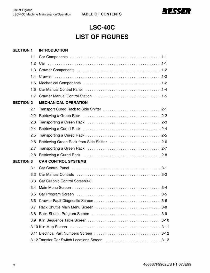
1.1 Car Components . . . . . . . . . . . . . . . . . . . . . . . . . . . . . . . . . . . . . . . . . .1-1
1.2 Car . . . . . . . . . . . . . . . . . . . . . . . . . . . . . . . . . . . . . . . . . . . . . . . . . . . .1-1
1.3 Crawler Components . . . . . . . . . . . . . . . . . . . . . . . . . . . . . . . . . . . . . . .1-2
1.4 Crawler . . . . . . . . . . . . . . . . . . . . . . . . . . . . . . . . . . . . . . . . . . . . . . . . .1-2
1.5 Mechanical Components . . . . . . . . . . . . . . . . . . . . . . . . . . . . . . . . . . . .1-2
1.6 Car Manual Control Panel . . . . . . . . . . . . . . . . . . . . . . . . . . . . . . . . . . .1-4
1.7 Crawler Manual Control Station . . . . . . . . . . . . . . . . . . . . . . . . . . . . . . .1-5
SECTION 2 MECHANICAL OPERATION
2.1 Transport Cured Rack to Side Shifter . . . . . . . . . . . . . . . . . . . . . . . . . . .2-1
2.2 Retrieving a Green Rack . . . . . . . . . . . . . . . . . . . . . . . . . . . . . . . . . . . .2-2
2.3 Transporting a Green Rack . . . . . . . . . . . . . . . . . . . . . . . . . . . . . . . . . .2-3
2.4 Retrieving a Cured Rack . . . . . . . . . . . . . . . . . . . . . . . . . . . . . . . . . . . .2-4
2.5 Transporting a Cured Rack . . . . . . . . . . . . . . . . . . . . . . . . . . . . . . . . . . .2-5
2.6 Retrieving Green Rack from Side Shifter . . . . . . . . . . . . . . . . . . . . . . . .2-6
2.7 Transporting a Green Rack . . . . . . . . . . . . . . . . . . . . . . . . . . . . . . . . . .2-7
2.8 Retrieving a Cured Rack . . . . . . . . . . . . . . . . . . . . . . . . . . . . . . . . . . . .2-8
SECTION 3 CAR CONTROL SYSTEMS
3.1 Car Control Panel . . . . . . . . . . . . . . . . . . . . . . . . . . . . . . . . . . . . . . . . .3-1
3.2 Car Manual Controls . . . . . . . . . . . . . . . . . . . . . . . . . . . . . . . . . . . . . . .3-2
3.3 Car Graphic Control Screen3-3
3.4 Main Menu Screen . . . . . . . . . . . . . . . . . . . . . . . . . . . . . . . . . . . . . . . . .3-4
3.5 Car Program Screen . . . . . . . . . . . . . . . . . . . . . . . . . . . . . . . . . . . . . . .3-5
3.6 Crawler Fault Diagnostic Screen . . . . . . . . . . . . . . . . . . . . . . . . . . . . . . .3-6
3.7 Rack Shuttle Main Menu Screen . . . . . . . . . . . . . . . . . . . . . . . . . . . . . .3-8
3.8 Rack Shuttle Program Screen . . . . . . . . . . . . . . . . . . . . . . . . . . . . . . . .3-9
3.9 Kiln Sequence Table Screen . . . . . . . . . . . . . . . . . . . . . . . . . . . . . . . . . .3-10
3.10 Kiln Map Screen . . . . . . . . . . . . . . . . . . . . . . . . . . . . . . . . . . . . . . . . . .3-11
3.11 Electrical Part Numbers Screen . . . . . . . . . . . . . . . . . . . . . . . . . . . . . . .3-12
3.12 Transfer Car Switch Locations Screen . . . . . . . . . . . . . . . . . . . . . . . . . .3-13
LSC-40C
LIST OF FIGURES

TABLE OF CONTENTS LSC-40C Machine Maintenance/Operation
v
List of Figures
466367F9902US F1 07JE99
3.13 Input/Output Status Screen . . . . . . . . . . . . . . . . . . . . . . . . . . . . . . . . . .3-15
3.14 Car Sensor Locations . . . . . . . . . . . . . . . . . . . . . . . . . . . . . . . . . . . . . . .3-16
3.15 Raillock Operation . . . . . . . . . . . . . . . . . . . . . . . . . . . . . . . . . . . . . . . . .3-18
3.16 Car Input/Output Modules . . . . . . . . . . . . . . . . . . . . . . . . . . . . . . . . . . .3-19
SECTION 4 CRAWLER CONTROL STATION
4.1 Crawler Control Station . . . . . . . . . . . . . . . . . . . . . . . . . . . . . . . . . . . . .4-1
4.2 Crawler Sensor Locations . . . . . . . . . . . . . . . . . . . . . . . . . . . . . . . . . . .4-2
4.3 Crawler Input/Output Modules . . . . . . . . . . . . . . . . . . . . . . . . . . . . . . . .4-4
SECTION 5 MAINTENANCE
5.1 Sensor Adjustments . . . . . . . . . . . . . . . . . . . . . . . . . . . . . . . . . . . . . . . .5-1
5.2 Pipe Threads . . . . . . . . . . . . . . . . . . . . . . . . . . . . . . . . . . . . . . . . . . . . .5-2
5.3 Flare Fitting . . . . . . . . . . . . . . . . . . . . . . . . . . . . . . . . . . . . . . . . . . . . . .5-3
5.4 Hydraulic Filter . . . . . . . . . . . . . . . . . . . . . . . . . . . . . . . . . . . . . . . . . . . .5-3
5.5 Cable Reel Assembly . . . . . . . . . . . . . . . . . . . . . . . . . . . . . . . . . . . . . . .5-6
5.6 Cable Winding . . . . . . . . . . . . . . . . . . . . . . . . . . . . . . . . . . . . . . . . . . . .5-6
5.7 Spring Replacement . . . . . . . . . . . . . . . . . . . . . . . . . . . . . . . . . . . . . . . .5-7
5.8 Lithium Battery and EEPROM . . . . . . . . . . . . . . . . . . . . . . . . . . . . . . . .5-10
SECTION 6 TROUBLESHOOTING
6.1 Car Battery, Fuses, EEPROM and Circuit Breakers . . . . . . . . . . . . . . . .6-2
6.2 Crawler Battery, Fuses, EEPROM and Circuit Breakers . . . . . . . . . . . . .6-3
6.3 External Hydraulic Valves . . . . . . . . . . . . . . . . . . . . . . . . . . . . . . . . . . . .6-4
List of TablesLSC-40C Machine Maintenance/Operation TABLE OF CONTENTS
vi 466367F9902US F1 07JE99
LSC-40C
LIST OF TABLES
SECTION 6 TROUBLESHOOTING
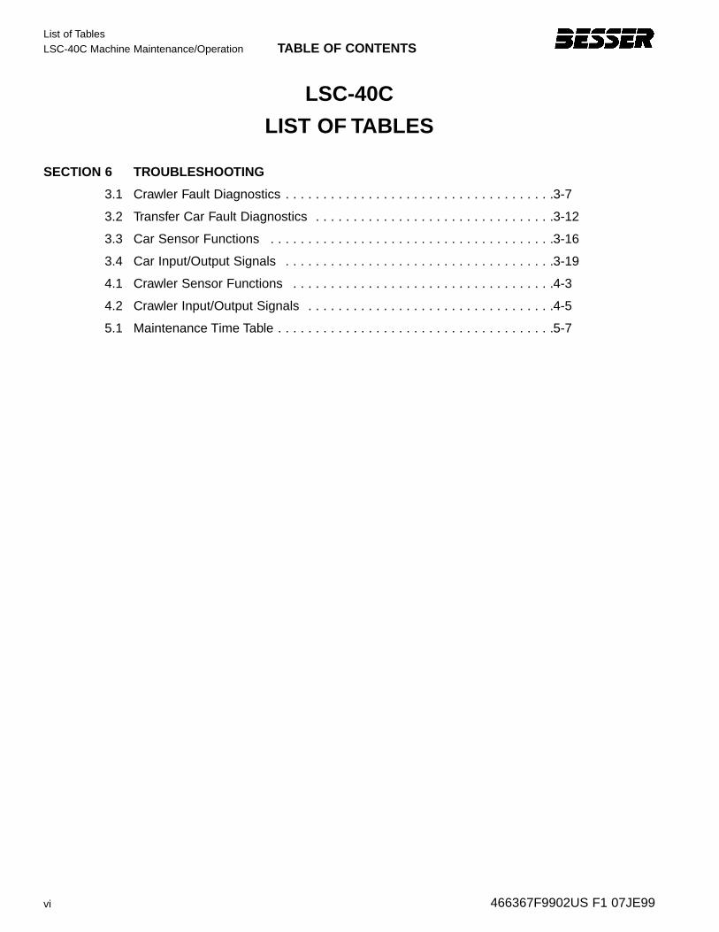
3.1 Crawler Fault Diagnostics . . . . . . . . . . . . . . . . . . . . . . . . . . . . . . . . . . . .3-7
3.2 Transfer Car Fault Diagnostics . . . . . . . . . . . . . . . . . . . . . . . . . . . . . . . .3-12
3.3 Car Sensor Functions . . . . . . . . . . . . . . . . . . . . . . . . . . . . . . . . . . . . . .3-16
3.4 Car Input/Output Signals . . . . . . . . . . . . . . . . . . . . . . . . . . . . . . . . . . . .3-19
4.1 Crawler Sensor Functions . . . . . . . . . . . . . . . . . . . . . . . . . . . . . . . . . . .4-3
4.2 Crawler Input/Output Signals . . . . . . . . . . . . . . . . . . . . . . . . . . . . . . . . .4-5
5.1 Maintenance Time Table . . . . . . . . . . . . . . . . . . . . . . . . . . . . . . . . . . . . .5-7
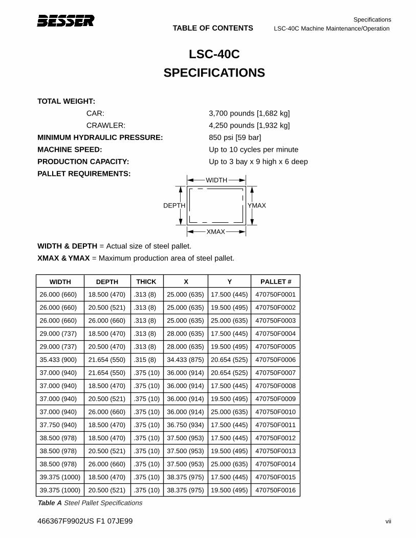
TABLE OF CONTENTS LSC-40C Machine Maintenance/Operation
vii
Specifications
466367F9902US F1 07JE99
LSC-40C
SPECIFICATIONS
TOTAL WEIGHT:
CAR: 3,700 pounds [1,682 kg]
CRAWLER: 4,250 pounds [1,932 kg]
MINIMUM HYDRAULIC PRESSURE: 850 psi [59 bar]
MACHINE SPEED: Up to 10 cycles per minute
PRODUCTION CAPACITY: Up to 3 bay x 9 high x 6 deep
PALLET REQ UIREMENTS:
WIDTH & DEPTH = Actual size of steel pallet.
XMAX & YMAX = Maximum production area of steel pallet.
WIDTH
XMAX
YMAXDEPTH
WIDTH
26.000 (660)
26.000 (660)
26.000 (660)
29.000 (737)
29.000 (737)
35.433 (900)
37.000 (940)
37.000 (940)
37.000 (940)
37.000 (940)
37.750 (940)
38.500 (978)
38.500 (978)
38.500 (978)
39.375 (1000)
39.375 (1000)
25.000 (635)
25.000 (635)
25.000 (635)
28.000 (635)
28.000 (635)
34.433 (875)
36.000 (914)
36.000 (914)
36.000 (914)
36.000 (914)
36.750 (934)
37.500 (953)
37.500 (953)
37.500 (953)
38.375 (975)
38.375 (975)
18.500 (470)
20.500 (521)
26.000 (660)
18.500 (470)
20.500 (470)
21.654 (550)
21.654 (550)
18.500 (470)
20.500 (521)
26.000 (660)
18.500 (470)
18.500 (470)
20.500 (521)
26.000 (660)
18.500 (470)
20.500 (521)
17.500 (445)
19.500 (495)
25.000 (635)
17.500 (445)
19.500 (495)
20.654 (525)
20.654 (525)
17.500 (445)
19.500 (495)
25.000 (635)
17.500 (445)
17.500 (445)
19.500 (495)
25.000 (635)
17.500 (445)
19.500 (495)
470750F0001
470750F0002
470750F0003
470750F0004
470750F0005
470750F0006
470750F0007
470750F0008
470750F0009
470750F0010
470750F0011
470750F0012
470750F0013
470750F0014
470750F0015
470750F0016
.313 (8)
.313 (8)
.313 (8)
.313 (8)
.313 (8)
.315 (8)
.375 (10)
.375 (10)
.375 (10)
.375 (10)
.375 (10)
.375 (10)
.375 (10)
.375 (10)
.375 (10)
.375 (10)
DEPTH THICK X Y PALLET #
Table A Steel Pallet Specifications
SpecificationsLSC-40C Machine Maintenance/Operation TABLE OF CONTENTS
viii 466367F9902US F1 07JE99
OPERATING CONDITIONS: Besser machinery and equipment is designed to comply with the essential health and safety regulations(EHSR) that apply to directives which are applicable toan industrial environment.Buyer shall utilize this equipment in a manner consistentwith its design and only in an industrial environment.
OPERATING RANGES: Here are the normal operating ranges for machinesensors (limit, proximity) and control devices contained within the control panels.
Ambient operating temperature rang e: 32° to 122°F [0° to 50°C]
Humidity rang e: 10 to 95% (non-condensing)
Line v olta ge: 90 to 132 volts – AC 50/60 Hz
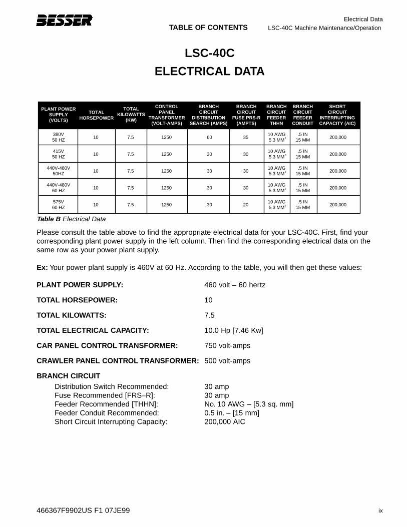
TABLE OF CONTENTS LSC-40C Machine Maintenance/Operation
ix
Electrical Data
466367F9902US F1 07JE99
LSC-40C
ELECTRICAL DATA
TOTALHORSEPOWER
PLANT POWERSUPPLY(VOLTS)
380V50 HZ
415V50 HZ
440V-480V50HZ
440V-480V60 HZ
575V60 HZ
10
10
10
10
10
7.5
7.5
7.5
7.5
7.5
1250
1250
1250
1250
1250
60
30
30
30
30
35
30
30
30
20
10 AWG5.3 MM
10 AWG5.3 MM
10 AWG5.3 MM
10 AWG5.3 MM
10 AWG5.3 MM
.5 IN15 MM
.5 IN15 MM
.5 IN15 MM
.5 IN15 MM
.5 IN15 MM
200,000
200,000
200,000
200,000
200,000
TOTALKILOWATTS
(KW)
CONTROLPANEL
TRANSFORMER(VOLT-AMPS)
BRANCHCIRCUIT
DISTRIBUTIONSEARCH (AMPS)
BRANCHCIRCUIT
FUSE PRS-R(AMPTS)
BRANCHCIRCUITFEEDER
THHN
BRANCH CIRCUITFEEDERCONDUIT
SHORTCIRCUIT
INTERRUPTINGCAPACITY (AIC)
2
2
2
2
2
Table B Electrical Data
Please consult the table above to find the appropriate electrical data for your LSC-40C. First, find yourcorresponding plant power supply in the left column. Then find the corresponding electrical data on thesame row as your power plant supply.
Ex: Your power plant supply is 460V at 60 Hz. According to the table, you will then get these values:
PLANT POWER SUPPLY: 460 volt – 60 hertz
TOTAL HORSEPOWER: 10
TOTAL KILO WATTS: 7.5
TOTAL ELECTRICAL CAP ACITY: 10.0 Hp [7.46 Kw]
CAR PANEL CONTROL TRANSFORMER: 750 volt-amps
CRAWLER PANEL CONTROL TRANSFORMER: 500 volt-amps
BRANCH CIRCUIT Distribution Switch Recommended: 30 ampFuse Recommended [FRS–R]: 30 ampFeeder Recommended [THHN]: No. 10 AWG – [5.3 sq. mm]Feeder Conduit Recommended: 0.5 in. – [15 mm]Short Circuit Interrupting Capacity: 200,000 AIC
Safety BulletinLSC-40C Machine Maintenance/Operation TABLE OF CONTENTS
x 466367F9902US F1 07JE99
SAFETY BULLETINThis notice is issued to advise you that some previously accepted shop practices may not be keeping upwith changing Federal and State Safety and Health Standards. Your current shop practices may notemphasize the need for proper precautions to insure safe operation and use of machines, tools, automaticloaders and allied equipment and/or warn against the use of certain solvents or other cleaning substancesthat are now considered unsafe or prohibited by law. Since many of your shop practices may not reflectcurrent safety practices and procedures, particularly with regard to the safe operation of equipment, it isimportant that you review your practices to ensure compliance with Federal and State Safety and HealthStandards.
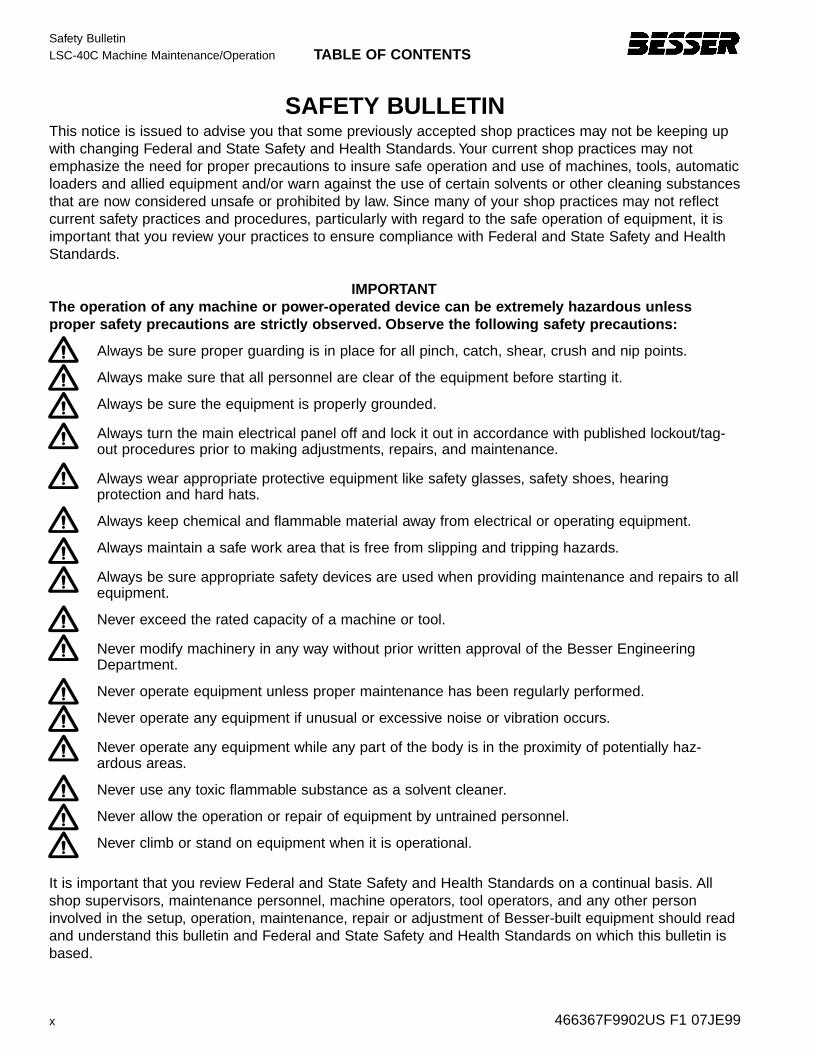
IMPORTANTThe operation of an y mac hine or po wer-operated de vice can be e xtremel y hazar dous unless proper saf ety precautions are strictl y obser ved. Obser ve the f ollo wing saf ety precautions:
Always be sure proper guarding is in place for all pinch, catch, shear, crush and nip points.
Always make sure that all personnel are clear of the equipment before starting it.
Always be sure the equipment is properly grounded.
Always turn the main electrical panel off and lock it out in accordance with published lockout/tag-out procedures prior to making adjustments, repairs, and maintenance.
Always wear appropriate protective equipment like safety glasses, safety shoes, hearing protection and hard hats.
Always keep chemical and flammable material away from electrical or operating equipment.
Always maintain a safe work area that is free from slipping and tripping hazards.
Always be sure appropriate safety devices are used when providing maintenance and repairs to allequipment.
Never exceed the rated capacity of a machine or tool.
Never modify machinery in any way without prior written approval of the Besser EngineeringDepartment.
Never operate equipment unless proper maintenance has been regularly performed.
Never operate any equipment if unusual or excessive noise or vibration occurs.
Never operate any equipment while any part of the body is in the proximity of potentially haz-ardous areas.
Never use any toxic flammable substance as a solvent cleaner.
Never allow the operation or repair of equipment by untrained personnel.
Never climb or stand on equipment when it is operational.
It is important that you review Federal and State Safety and Health Standards on a continual basis. Allshop supervisors, maintenance personnel, machine operators, tool operators, and any other personinvolved in the setup, operation, maintenance, repair or adjustment of Besser-built equipment should readand understand this bulletin and Federal and State Safety and Health Standards on which this bulletin isbased.

TABLE OF CONTENTS LSC-40C Machine Maintenance/Operation
xi
Safety Signs
466367F9902US F1 07JE99
SAFETY SIGNSSign Description Required1 All Panels ............................................................................................................12 Mixer ...................................................................................................................43 Concrete Products Machine................................................................................1
Depalleter............................................................................................................24 Mixer ...................................................................................................................25 Skiploader ...........................................................................................................46 Skiploader/Mixer Platforms .................................................................................87 Skiploader/Mixer Platforms .................................................................................88 Vertical: Pallet Transport System ........................................................................2
Horizontal: LSC-40/LSC-100...............................................................................6Pallet Transport System ......................................................................................4
9 Besser-Matic .......................................................................................................410 Besser-Matic .......................................................................................................411 Skiploader ...........................................................................................................412 All Panels ............................................................................................................113 Overhead Block Transfer.....................................................................................414 Concrete Products Machine................................................................................115 Concrete Products Machine................................................................................216 Conveyors .........................................................................................................1217 Cuber ..................................................................................................................818 Cuber ..................................................................................................................3
Block Turnovers...................................................................................................2Slat Conveyors ....................................................................................................2
To or der saf ety decals, contact y our local Besser representativeor the Besser Central Or der Depar tment.
Thank y ou!
Safety SignsLSC-40C Machine Maintenance/Operation TABLE OF CONTENTS
xii 466367F9902US F1 07JE99
DDANGERANGER
PELIGRPELIGROO
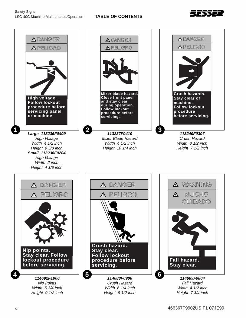
Mixer blade hazard.Close front paneland stay clearduring operation.Follow lockout procedure before servicing.
113237F0410Mixer Blade Hazard
Width 4 1/2 inchHeight 10 1/4 inch
DDANGERANGER
PELIGRPELIGROO
High voltage.Follow lockoutprocedure beforeservicing panel or machine.
Large 113236F0409High Voltage
Width 4 1/2 inchHeight 9 5/8 inch
Small 113236F0204High VoltageWidth 2 inch
Height 4 1/8 inch
DDANGERANGER
PELIGRPELIGROO
Crush hazards.Stay clear ofmachine.Follow lockoutprocedurebefore servicing.
113240F0307Crush Hazard
Width 3 1/2 inchHeight 7 1/2 inch
DDANGERANGER
PELIGRPELIGROO
Crush hazard.Stay clear.Follow lockoutprocedure beforeservicing.
114688F0906Crush Hazard
Width 6 1/4 inchHeight 9 1/2 inch
DDANGERANGER
PELIGRPELIGROO
Nip points.Stay clear. Followlockout procedurebefore servicing.
114692F1006Nip Points
Width 5 3/4 inchHeight 9 1/2 inch
WWARNINGARNING
MUCHOMUCHOCUIDCUIDADOADO
Fall hazard.Stay clear.
114689F0804Fall Hazard
Width 4 1/2 inchHeight 7 3/4 inch
1 2 3
4 5 6
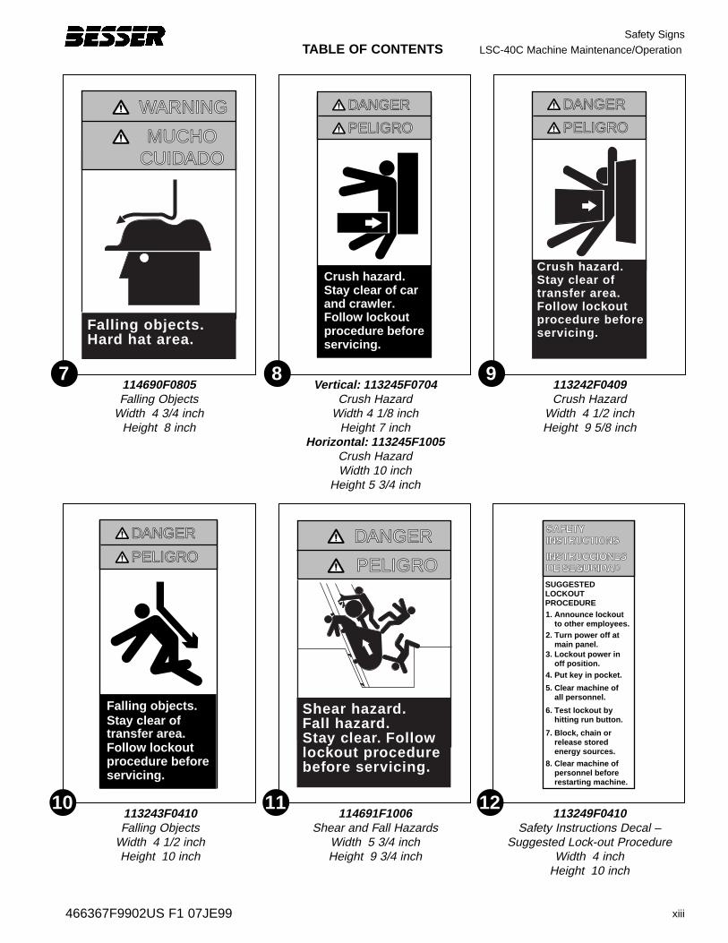
TABLE OF CONTENTS LSC-40C Machine Maintenance/Operation
xiii
Safety Signs
466367F9902US F1 07JE99
Crush hazard.Stay clear of carand crawler.Follow lockoutprocedure beforeservicing.
DDANGERANGER
PELIGRPELIGROO
Vertical: 113245F0704Crush Hazard
Width 4 1/8 inchHeight 7 inch
Horizontal: 113245F1005Crush HazardWidth 10 inch
Height 5 3/4 inch
WWARNINGARNING
MUCHOMUCHOCUIDCUIDADOADO
Falling objects.Hard hat area.
114690F0805Falling Objects
Width 4 3/4 inchHeight 8 inch
DDANGERANGER
PELIGRPELIGROO
Crush hazard.Stay clear oftransfer area.Follow lockout procedure beforeservicing.
113242F0409Crush Hazard
Width 4 1/2 inchHeight 9 5/8 inch
DDANGERANGER
PELIGRPELIGROO
Shear hazard.Fall hazard.Stay clear. Followlockout procedurebefore servicing.
114691F1006Shear and Fall Hazards
Width 5 3/4 inchHeight 9 3/4 inch
SUGGESTEDLOCKOUTPROCEDURE1. Announce lockout to other employees.2. Turn power off at main panel.3. Lockout power in off position.4. Put key in pocket.
5. Clear machine of all personnel.
6. Test lockout by hitting run button.
7. Block, chain or release stored energy sources.
8. Clear machine of personnel before restarting machine.
113249F0410Safety Instructions Decal –
Suggested Lock-out ProcedureWidth 4 inch
Height 10 inch
Falling objects.Stay clear oftransfer area.Follow lockoutprocedure beforeservicing.
DDANGERANGER
PELIGRPELIGROO
113243F0410Falling Objects
Width 4 1/2 inchHeight 10 inch
7 9
11
8
10 12
Safety SignsLSC-40C Machine Maintenance/Operation TABLE OF CONTENTS
xiv 466367F9902US F1 07JE99
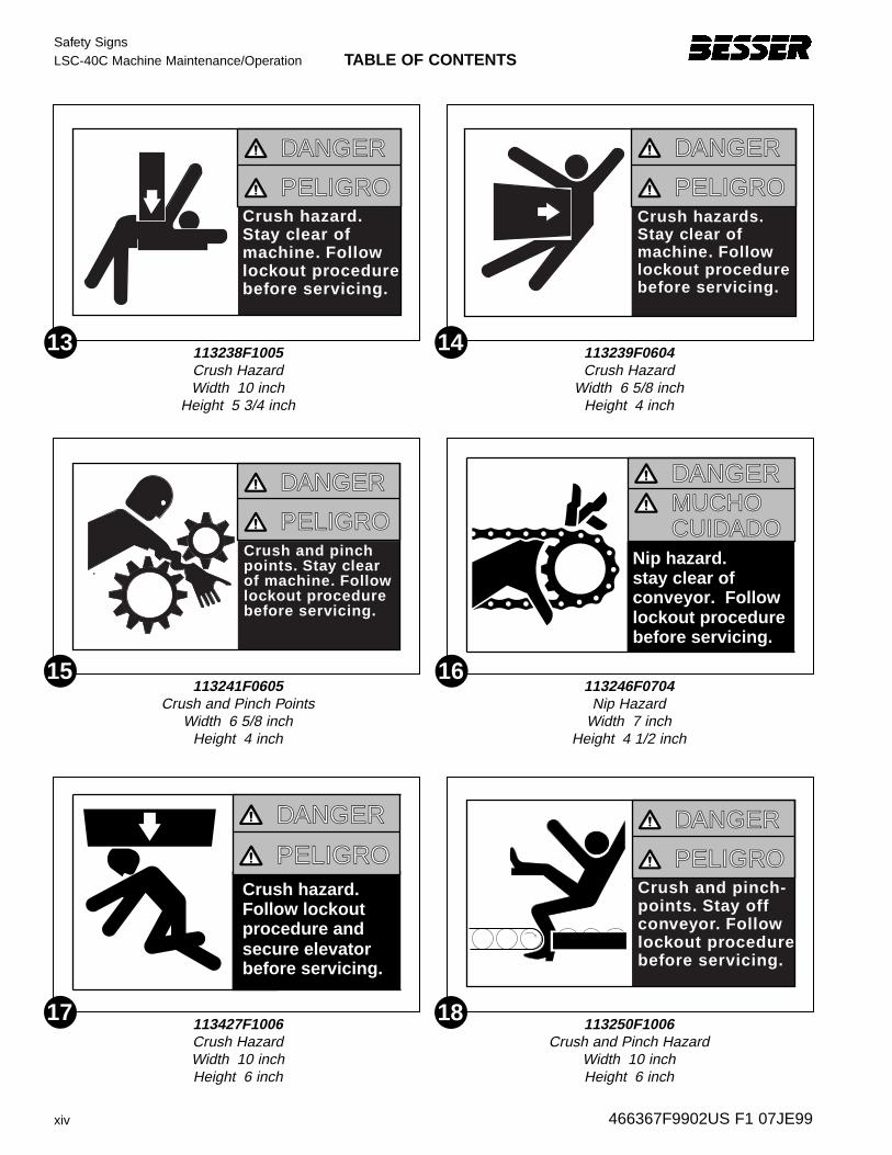
DDANGERANGER
PELIGRPELIGROOCrush hazard.Stay clear of machine. Follow lockout procedure before servicing.
DDANGERANGER
PELIGRPELIGROOCrush hazards.Stay clear of machine. Follow lockout procedure before servicing.
113238F1005Crush HazardWidth 10 inch
Height 5 3/4 inch
113239F0604Crush Hazard
Width 6 5/8 inchHeight 4 inch
DDANGERANGER
PELIGRPELIGROOCrush and pinchpoints. Stay clearof machine. Followlockout procedurebefore servicing.
Nip hazard.
lockout procedureconveyor. Follow
before servicing.
stay clear of
DDANGERANGERMUCHOMUCHOCUIDCUIDADOADO
113241F0605Crush and Pinch Points
Width 6 5/8 inchHeight 4 inch
113246F0704Nip Hazard
Width 7 inchHeight 4 1/2 inch
Crush hazard.
secure elevatorprocedure and
before servicing.
Follow lockout
DDANGERANGER
PELIGRPELIGROODDANGERANGER
PELIGRPELIGROOCrush and pinch-points. Stay off conveyor. Followlockout procedurebefore servicing.
113427F1006Crush HazardWidth 10 inchHeight 6 inch
113250F1006Crush and Pinch Hazard
Width 10 inchHeight 6 inch
13
15
14
17
16
18
1-1466367F9902US F1 07JE99
MAINTENANCE/OPERATION LSC-40C Machine Maintenance/Operation
SECTION 1
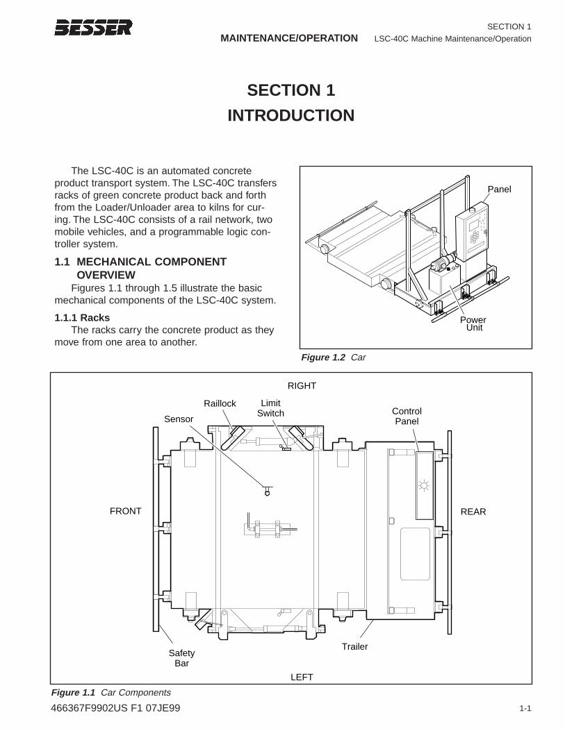
The LSC-40C is an automated concreteproduct transport system. The LSC-40C transfersracks of green concrete product back and forthfrom the Loader/Unloader area to kilns for cur-ing. The LSC-40C consists of a rail network, twomobile vehicles, and a programmable logic con-troller system.
1.1 MECHANICAL COMPONENT OVERVIEW
Figures 1.1 through 1.5 illustrate the basicmechanical components of the LSC-40C system.
1.1.1 RacksThe racks carry the concrete product as they
move from one area to another.
SECTION 1
INTRODUCTION
Raillock
Sensor
LimitSwitch Control
Panel
TrailerSafety
Bar
RIGHT
LEFT
REARFRONT
Figure 1.1 Car Components
Panel
Power Unit
Figure 1.2 Car
SECTION 1
LSC-40C Machine Maintenance/Operation MAINTENANCE/OPERATION
1-2 466367F9902US F1 07JE99
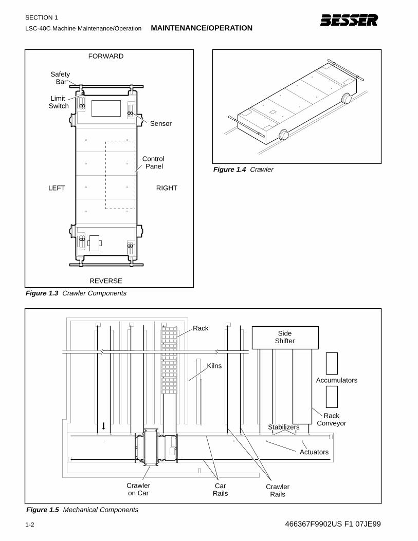
Figure 1.4 Crawler
Kilns
Crawleron Car
CrawlerRails
CarRails
Rack
Actuators
SideShifter
Rack Conveyor
Accumulators
Stabilizers
Figure 1.5 Mechanical Components
Sensor
FORWARD
REVERSE
RIGHTLEFT
Control Panel
Limit Switch
Safety Bar
Figure 1.3 Crawler Components
MAINTENANCE/OPERATION LSC-40C Machine Maintenance/Operation
1-3
SECTION 1
466367F9902US F1 07JE99
1.1.2 Rail SystemThere are two different rail paths and gauges.
Wide gauge rails carry the car. Narrow gaugerails at right angles to the car rails carry thecrawler to the side shifter, the rack conveyor andinto the kilns.
1.1.3 CrawlerThe crawler lifts and transports racks between
the car and the:• Side shifter• Rack conveyor • Kilns
1.1.4 CarThe car carries the crawler between the
Loader/Unloader area and the kiln area.
1.1.5 Side ShifterThe side shifter loads, shifts and stores racks
until removed by the crawler.
1.1.6 Rack ConveyorThe rack conveyor receives cured racks from
the crawler and transports them to the Unloader.
1.2 ELECTRONIC COMPONENTOVERVIEWA range of electronic components monitor and
control LSC-40C operation. This section providesonly a brief overview of three components thatare fundamental to the mechanical operation ofthe system:
• Logic controller/graphic control station• Sensors• ActuatorsSections 3 and 4 provide details of electronic
components including sensor function.
1.2.1 Small Logic Contr oller/Graphic Contr ol Station
Both car and crawler have Small LogicControllers (SLC-500) which control the sequenceof operations of each vehicle. The car’s graphiccontrol station functions as a man-machine inter-face. The crawler has two control stations locatedat each end of the crawler. The control stationsuse indicator lamps to show operational statusand faults.
1.2.2 Sensor sSensors located on the car and crawler moni-
tor and control all mechanical operations. Sensorsare also essential to the LSC-40C safety protec-tion system. There are three types of sensors:
• Limit switches (LS) are spring-loadedelectromechanical devices that monitor theposition of:– Safety bars on both the car and crawler– Car raillocks
• Proximity sensors (PRS) on both the carand the crawler monitor a magnetic field tosignal various operating conditions. Forexample, upward-sensing PRSs on thecrawler detect the presence of a rack aspart of the control process for crawler move-ment. Downward-sensing PRSs on the cardetect floor-level actuators as part of thecontrol process for car movement.
• A photo-electric sensor (PER) provides alight and reflection process as a means bywhich crawler movements are controlledwhen traveling on the rails leading to theside shifter.
1.2.3 Actuator sActuators are floor-level steel plates installed
on the centerline of every set of crawler rails.Downward-sensing proximity sensors on the caruse the actuators to help control car movement.
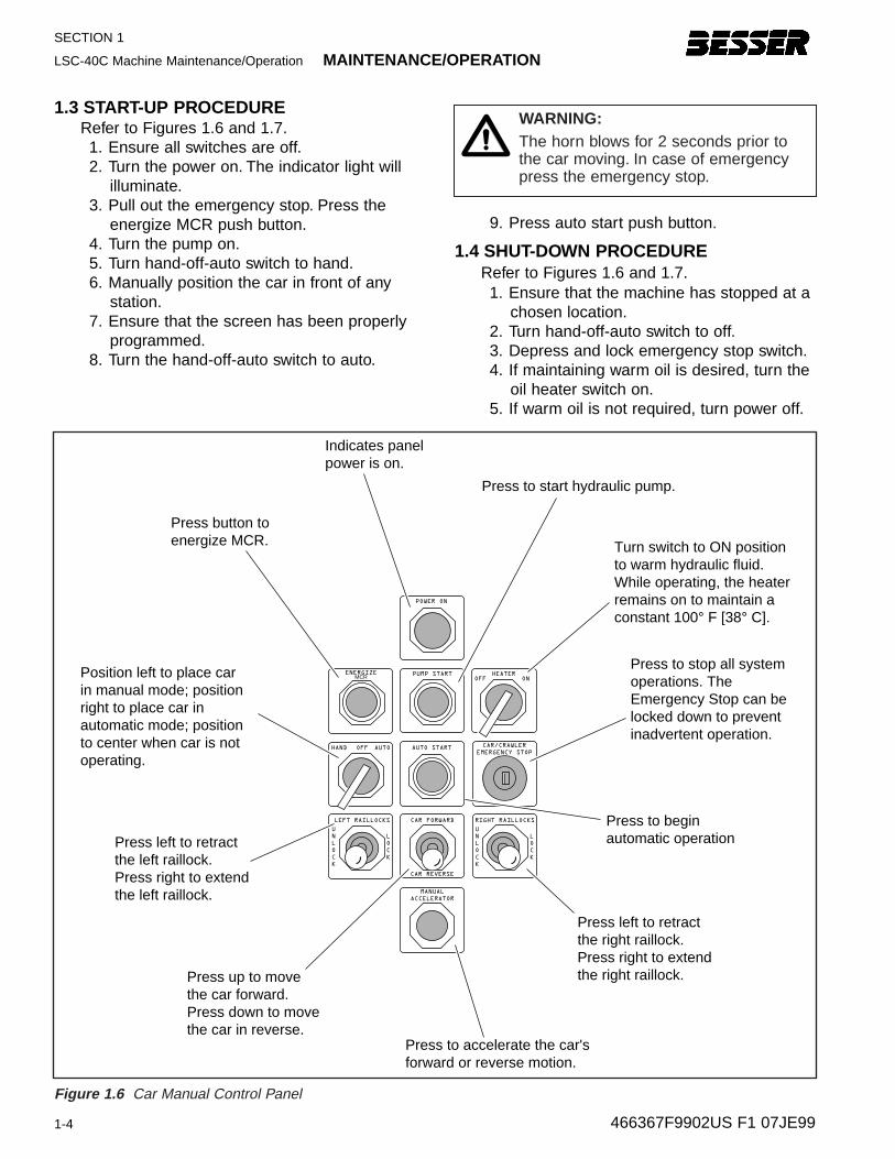
1.3 START-UP PROCEDURERefer to Figures 1.6 and 1.7.1. Ensure all switches are off.2. Turn the power on. The indicator light will
illuminate.3. Pull out the emergency stop. Press the
energize MCR push button.4. Turn the pump on.5. Turn hand-off-auto switch to hand.6. Manually position the car in front of any
station.7. Ensure that the screen has been properly
programmed.8. Turn the hand-off-auto switch to auto.
9. Press auto start push button.
1.4 SHUT-DOWN PROCEDURERefer to Figures 1.6 and 1.7.1. Ensure that the machine has stopped at a
chosen location.2. Turn hand-off-auto switch to off.3. Depress and lock emergency stop switch.4. If maintaining warm oil is desired, turn the
oil heater switch on.5. If warm oil is not required, turn power off.
SECTION 1
LSC-40C Machine Maintenance/Operation MAINTENANCE/OPERATION
1-4 466367F9902US F1 07JE99
HEATEROFF ON
OFF
LEFT RAILLOCKS RIGHT RAILLOCKSCAR FORWARD
MANUAL
ACCELERATOR
CAR/CRAWLER
EMERGENCY STOPAUTOHAND
PUMP STARTENERGIZEMCR
POWER ON
Indicates panelpower is on.
Press button toenergize MCR.
Press to stop all systemoperations. TheEmergency Stop can belocked down to preventinadvertent operation.
Press left to retract the left raillock.Press right to extend the left raillock.
Press up to move the car forward.Press down to move the car in reverse.
Press to accelerate the car'sforward or reverse motion.
Press left to retract the right raillock.Press right to extend the right raillock.
Press to start hydraulic pump.
Turn switch to ON positionto warm hydraulic fluid.While operating, the heater remains on to maintain a constant 100° F [38° C].
Position left to place carin manual mode; position right to place car inautomatic mode; positionto center when car is notoperating.
Press to begin automatic operation
AUTO START
CAR REVERSE
U
N
L
O
C
K
L
O
C
K
U
N
L
O
C
K
L
O
C
K
Figure 1.6 Car Manual Control Panel
WARNING:The horn blows for 2 seconds prior tothe car moving. In case of emergencypress the emergency stop.
MAINTENANCE/OPERATION LSC-40C Machine Maintenance/Operation
1-5
SECTION 1
466367F9902US F1 07JE99
LOADER
1
R R R
G
R R
R R R
2 3 4
STATION/FAULT
FAULTSTATION INCREMENT
KILN STORAGE UNLOADERCRAWLER
CENTERED
PENDANT STATION
EXTENDED
OIL HEATER
AUTO START CRAWLER EMERGENCY
STOPPULL TO
START
PUSH TO
STOP
HAND OFF AUTO
PUMP STARTDOWN UP
ELEVATOR
OFF
HEATER
ON
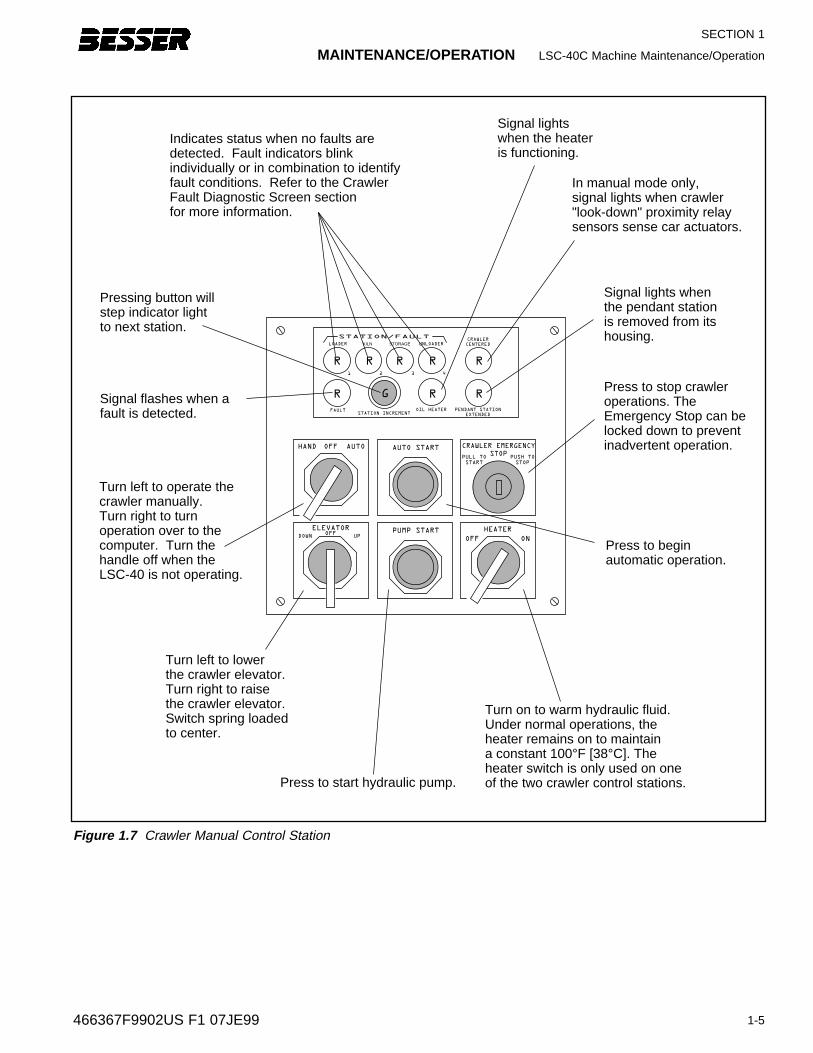
Press to stop crawleroperations. TheEmergency Stop can belocked down to preventinadvertent operation.
Press to beginautomatic operation.
Signal lights whenthe pendant stationis removed from its housing.
Pressing button willstep indicator lightto next station.
Signal flashes when a fault is detected.
In manual mode only,signal lights when crawler "look-down" proximity relay sensors sense car actuators.
Signal lightswhen the heateris functioning.
Indicates status when no faults are detected. Fault indicators blink individually or in combination to identify fault conditions. Refer to the Crawler Fault Diagnostic Screen sectionfor more information.
Press to start hydraulic pump.
Turn on to warm hydraulic fluid.Under normal operations, theheater remains on to maintaina constant 100°F [38°C]. The heater switch is only used on one of the two crawler control stations.
Turn left to operate the crawler manually. Turn right to turnoperation over to thecomputer. Turn thehandle off when theLSC-40 is not operating.
Turn left to lower the crawler elevator.Turn right to raise the crawler elevator.Switch spring loadedto center.
OFF
Figure 1.7 Crawler Manual Control Station

SECTION 1
LSC-40C Machine Maintenance/Operation MAINTENANCE/OPERATION
1-6 466367F9902US F1 07JE99
2-1466367F9902US F1 07JE99
MAINTENANCE/OPERATION LSC-40C Machine Maintenance/Operation
SECTION 2
SECTION 2
MECHANICAL OPERATION
This section is an overview of LSC-40C operation with a focus on mechanical systemsand movement of components. Steps in a typicaloperating cycle of the Unloader side shifter are:
• 2.1 Transport Cured Rack to Side Shifter• 2.2 Retrieve Green Rack from Rack
Conveyor• 2.3 Transport Green Rack to Kiln• 2.4 Retrieve Cured Rack from StorageSteps in a typical operating cycle of the
Loader side shifter are:• 2.5 Transport Cured Rack to Rack Conveyor• 2.6 Retrieve Green Rack from Side Shifter• 2.7 Transport Green Rack to Kiln• 2.8 Retrieve Cured Rack from Storage
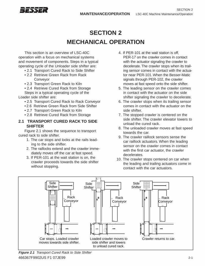
2.1 TRANSPORT CURED RACK TO SIDESHIFTER
Figure 2.1 shows the sequence to transportcured rack to side shifter.
1. The car stops and locks at the rails lead-ing to the side shifter.
2. The raillocks extend and the crawler imme-diately moves off the car at fast speed.
3. If PER-101 at the wait station is on, thecrawler proceeds towards the side shifterwithout stopping.
4. If PER-101 at the wait station is off, PER-17 on the crawler comes in contactwith the actuator signaling the crawler todecelerate. The crawler stops when its trail-ing sensor comes in contact with the actua-tor near PER-101. When the Besser-Maticsignals through PER-102, the crawlermoves at fast speed onto the side shifter.
5. The leading sensor on the crawler comesin contact with the actuator on the sideshifter signaling the crawler to decelerate.
6. The crawler stops when its trailing sensorcomes in contact with the actuator on theside shifter.
7. The stopped crawler is centered on theside shifter. The crawler elevator lowers tounload the cured rack.
8. The unloaded crawler moves at fast speedtowards the car.
9. The crawler raillock sensors sense the car raillock actuators. When the leadingsensor on the crawler comes in contactwith the first car actuator, the crawlerdecelerates.
10. The crawler stops centered on car whenthe leading and trailing actuators come incontact with the car actuators.
SideShifter
RackConveyor
Car stops. Loaded crawler moves towards side shifter.
Loaded crawler moves toside shifter and lowers to unload cured rack.
Crawler returns to car.
SideShifter
SideShifter
SideShifter
RackConveyor
RackConveyor
SideShifter
Figure 2.1 Transport Cured Rack to Side Shifter
2-2 466367F9902US F1 07JE99
SECTION 2LSC-40C Machine Maintenance/Operation MAINTENANCE/OPERATION
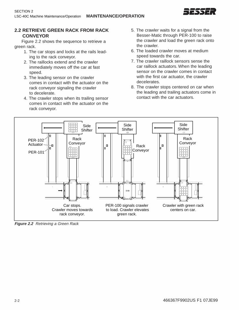
2.2 RETRIEVE GREEN RACK FROM RACKCONVEYORFigure 2.2 shows the sequence to retrieve a
green rack.1. The car stops and locks at the rails lead-
ing to the rack conveyor.2. The raillocks extend and the crawler
immediately moves off the car at fastspeed.
3. The leading sensor on the crawler comes in contact with the actuator on therack conveyor signaling the crawler to decelerate.
4. The crawler stops when its trailing sensorcomes in contact with the actuator on therack conveyor.
5. The crawler waits for a signal from theBesser-Matic through PER-100 to raisethe crawler and load the green rack ontothe crawler.
6. The loaded crawler moves at mediumspeed towards the car.
7. The crawler raillock sensors sense the car raillock actuators. When the leadingsensor on the crawler comes in contactwith the first car actuator, the crawlerdecelerates.
8. The crawler stops centered on car whenthe leading and trailing actuators come incontact with the car actuators.
RackConveyor
PER-102Actuator
PER-101
Car stops.Crawler moves towards
rack conveyor.
PER-100 signals crawler to load. Crawler elevates
green rack.
Crawler with green rackcenters on car.
SideShifter
RackConveyor
SideShifter
RackConveyor
SideShifter
SideShifter
SideShifter
Figure 2.2 Retrieving a Green Rack
2-3466367F9902US F1 07JE99
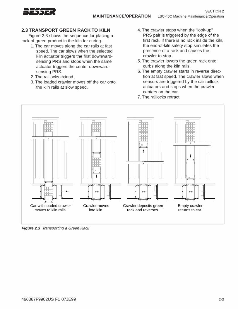
2.3 TRANSPORT GREEN RACK TO KILNFigure 2.3 shows the sequence for placing a
rack of green product in the kiln for curing.1. The car moves along the car rails at fast
speed. The car slows when the selectedkiln actuator triggers the first downward-sensing PRS and stops when the sameactuator triggers the center downward-sensing PRS.
2. The raillocks extend.3. The loaded crawler moves off the car onto
the kiln rails at slow speed.
MAINTENANCE/OPERATION LSC-40C Machine Maintenance/Operation
SECTION 2
4. The crawler stops when the “look-up”PRS pair is triggered by the edge of thefirst rack. If there is no rack inside the kiln,the end-of-kiln safety stop simulates thepresence of a rack and causes thecrawler to stop.
5. The crawler lowers the green rack ontocurbs along the kiln rails.
6. The empty crawler starts in reverse direc-tion at fast speed. The crawler slows whensensors are triggered by the car raillockactuators and stops when the crawlercenters on the car.
7. The raillocks retract.
Car with loaded crawlermoves to kiln rails.
Crawler movesinto kiln.
Crawler deposits greenrack and reverses.
Empty crawlerreturns to car.
Figure 2.3 Transporting a Green Rack
SECTION 2
LSC-40C Machine Maintenance/Operation MAINTENANCE/OPERATION
2-4 466367F9902US F1 07JE99
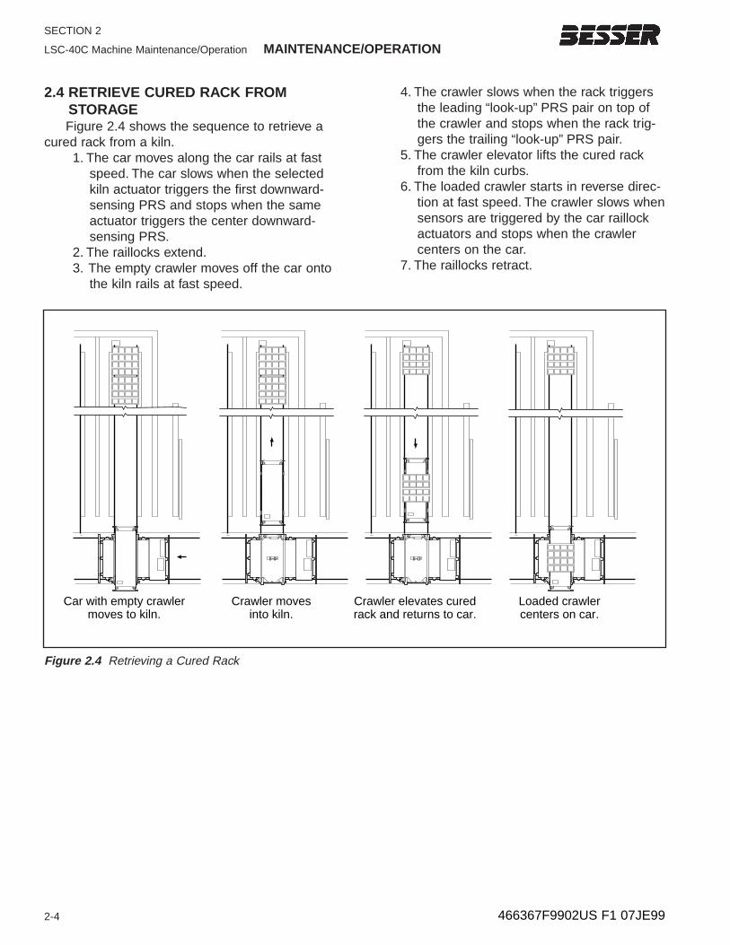
2.4 RETRIEVE CURED RACK FROM STORAGEFigure 2.4 shows the sequence to retrieve a
cured rack from a kiln.1. The car moves along the car rails at fast
speed. The car slows when the selectedkiln actuator triggers the first downward-sensing PRS and stops when the sameactuator triggers the center downward-sensing PRS.
2. The raillocks extend.3. The empty crawler moves off the car onto
the kiln rails at fast speed.
4. The crawler slows when the rack triggersthe leading “look-up” PRS pair on top ofthe crawler and stops when the rack trig-gers the trailing “look-up” PRS pair.
5. The crawler elevator lifts the cured rackfrom the kiln curbs.
6. The loaded crawler starts in reverse direc-tion at fast speed. The crawler slows whensensors are triggered by the car raillockactuators and stops when the crawlercenters on the car.
7. The raillocks retract.
Car with empty crawlermoves to kiln.
Crawler movesinto kiln.
Crawler elevates curedrack and returns to car.
Loaded crawlercenters on car.
Figure 2.4 Retrieving a Cured Rack
MAINTENANCE/OPERATION LSC-40 Machine Maintenance/Operation
2-5
SECTION 2
466367F9902US F1 07JE99
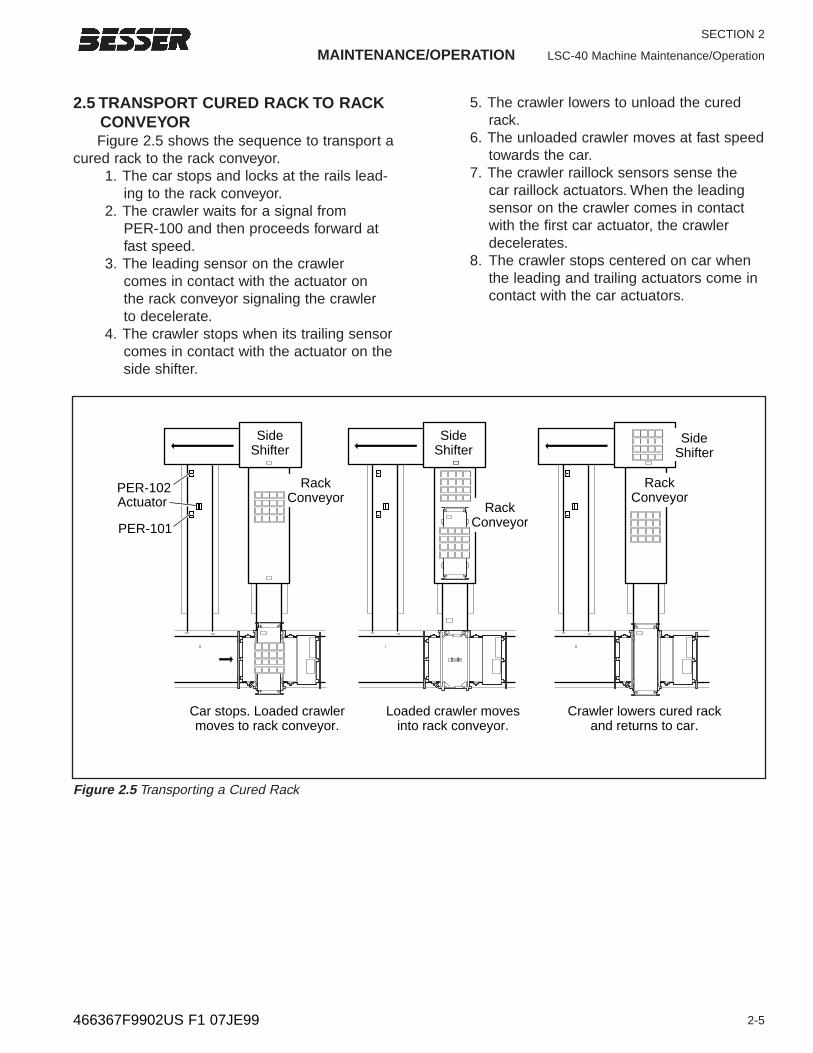
2.5 TRANSPORT CURED RACK TO RACKCONVEYORFigure 2.5 shows the sequence to transport a
cured rack to the rack conveyor.1. The car stops and locks at the rails lead-
ing to the rack conveyor.2. The crawler waits for a signal from
PER-100 and then proceeds forward atfast speed.
3. The leading sensor on the crawler comes in contact with the actuator on the rack conveyor signaling the crawler to decelerate.
4. The crawler stops when its trailing sensorcomes in contact with the actuator on theside shifter.
5. The crawler lowers to unload the curedrack.
6. The unloaded crawler moves at fast speedtowards the car.
7. The crawler raillock sensors sense the car raillock actuators. When the leadingsensor on the crawler comes in contactwith the first car actuator, the crawlerdecelerates.
8. The crawler stops centered on car whenthe leading and trailing actuators come incontact with the car actuators.
RackConveyor
Car stops. Loaded crawlermoves to rack conveyor.
Loaded crawler moves into rack conveyor.
Crawler lowers cured rackand returns to car.
RackConveyor
RackConveyor
SideShifter
SideShifter
SideShifter
PER-102Actuator
PER-101
Figure 2.5 Transporting a Cured Rack
SECTION 2
LSC-40 Machine Maintenance/Operation MAINTENANCE/OPERATION
2-6 466367F9902US F1 07JE99
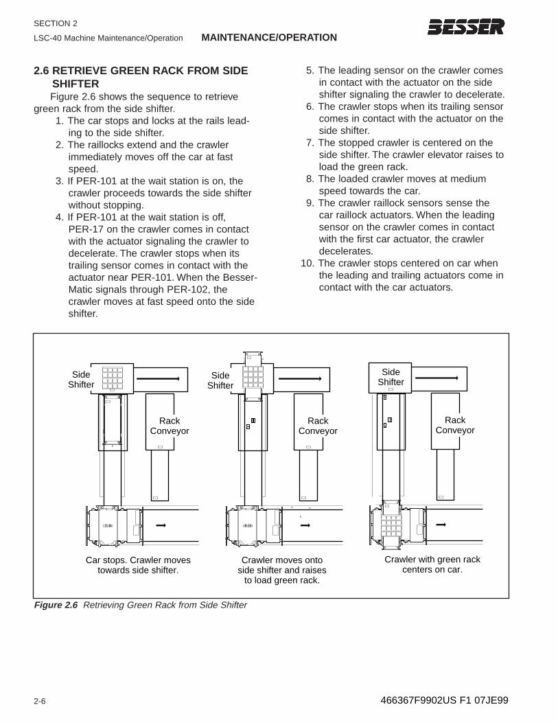
2.6 RETRIEVE GREEN RACK FROM SIDESHIFTERFigure 2.6 shows the sequence to retrieve
green rack from the side shifter.1. The car stops and locks at the rails lead-
ing to the side shifter.2. The raillocks extend and the crawler
immediately moves off the car at fastspeed.
3. If PER-101 at the wait station is on, thecrawler proceeds towards the side shifterwithout stopping.
4. If PER-101 at the wait station is off, PER-17 on the crawler comes in contactwith the actuator signaling the crawler todecelerate. The crawler stops when itstrailing sensor comes in contact with theactuator near PER-101. When the Besser-Matic signals through PER-102, thecrawler moves at fast speed onto the sideshifter.
5. The leading sensor on the crawler comesin contact with the actuator on the sideshifter signaling the crawler to decelerate.
6. The crawler stops when its trailing sensorcomes in contact with the actuator on theside shifter.
7. The stopped crawler is centered on theside shifter. The crawler elevator raises toload the green rack.
8. The loaded crawler moves at mediumspeed towards the car.
9. The crawler raillock sensors sense the car raillock actuators. When the leadingsensor on the crawler comes in contactwith the first car actuator, the crawlerdecelerates.
10. The crawler stops centered on car whenthe leading and trailing actuators come incontact with the car actuators.
SideShifter
RackConveyor
Car stops. Crawler moves towards side shifter.
Crawler moves onto side shifter and raises
to load green rack.
Crawler with green rackcenters on car.
SideShifter
SideShifter
SideShifter
RackConveyor
RackConveyor
SideShifter
Figure 2.6 Retrieving Green Rack from Side Shifter

MAINTENANCE/OPERATION LSC-40 Machine Maintenance/Operation
2-7
SECTION 2
466367F9902US F1 07JE99
2.7 TRANSPORT GREEN RACK TO KILNFigure 2.7 shows the sequence for placing a
rack of green product in the kiln for curing.1. The car moves along the car rails at fast
speed. The car slows when the selectedkiln actuator triggers the first downward-sensing PRS and stops when the sameactuator triggers the center downward-sensing PRS.
2. The raillocks extend.3. The loaded crawler moves off the car onto
the kiln rails at slow speed.
4. The crawler stops when the “look-up”PRS pair is triggered by the edge of thefirst rack. If there is no rack inside the kiln,the end-of-kiln safety stop simulates thepresence of a rack and causes thecrawler to stop.
5. The crawler lowers the green rack ontocurbs along the kiln rails.
6. The empty crawler starts in reverse direc-tion at fast speed. The crawler slows whensensors are triggered by the car raillockactuators and stops when the crawlercenters on the car.
7. The raillocks retract.
Car with loaded crawlermoves to kiln rails.
Crawler movesinto kiln.
Crawler deposits greenrack and reverses.
Empty crawlerreturns to car.
Figure 2.7 Transporting a Green Rack

SECTION 2
LSC-40 Machine Maintenance/Operation MAINTENANCE/OPERATION
2-8 466367F9902US F1 07JE99
2.8 RETRIEVE CURED RACK FROM STORAGEFigure 2.8 shows the sequence to retrieve a
cured rack from a kiln.1. The car moves along the car rails at fast
speed. The car slows when the selectedkiln actuator triggers the first downward-sensing PRS and stops when the sameactuator triggers the center downward-sensing PRS.
2. The raillocks extend.3. The empty crawler moves off the car onto
the kiln rails at fast speed.
4. The crawler slows when the rack triggersthe leading “look-up” PRS pair on top ofthe crawler and stops when the rack trig-gers the trailing “look-up” PRS pair.
5. The crawler elevator lifts the cured rackfrom the kiln curbs.
6. The loaded crawler starts in reverse direc-tion at fast speed. The crawler slows whensensors are triggered by the car raillockactuators and stops when the crawlercenters on the car.
7. The raillocks retract.
Car with empty crawlermoves to kiln.
Crawler movesinto kiln.
Crawler elevates curedrack and returns to car.
Loaded crawlercenters on car.
Figure 2.8 Retrieving a Cured Rack
MAINTENANCE/OPERATION LSC-40C Machine Maintenance/Operation
3-1
SECTION 3
466367F9902US F1 07JE99
LOCATION:
SEQUENCE:
LOADING KILN:
RACK COUNT:
UNLOADING KILN:
F1PROGRAM
CAR
F2RESET
RACK
ALARM
F3RAIL
LOCKS
ENABLED
F4CRAWLER
DIAG.
CENTER
F5KILN
MAP
F6INPUT/
OUTPUT
STATUS
F7 F8DATA
TABLE
DISPLAY
SENSOR
WIRING &
LOCATION
CAR INFORMATION:
OPERATOR ACTION:
OPERATOR MESSAGE CENTER
MAIN MENU
F9
F1
F10
F2
F11
F3
F12
F4
F13
F5
F14
F6
F15
F7
F16
F8
A
D
7
4
1
0. -
B
E
8
5
2
C
F
9
6
3
HEATEROFF ON
OFF
LEFT RAILLOCKS RIGHT RAILLOCKSCAR FORWARD
MANUAL
ACCELERATOR
AUTO START CAR/CRAWLER
EMERGENCY STOPAUTOHAND
PUMP STARTENERGIZEMCR
POWER ON
U
N
L
O
C
K
L
O
C
K
U
N
L
O
C
K
L
O
C
K
CAR REVERSE
Figure 3.1 Car Control Panel
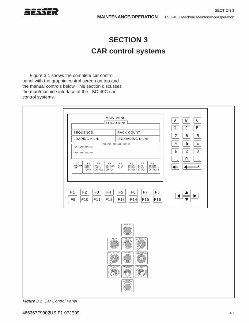
SECTION 3
CAR control systems
Figure 3.1 shows the complete car controlpanel with the graphic control screen on top andthe manual controls below. This section discussesthe man/machine interface of the LSC-40C carcontrol systems.
SECTION 3
LSC-40A Machine Maintenance/Operation MAINTENANCE/OPERATION
3-2 466367F9902US F1 07JE99
HEATEROFF ON
OFF
LEFT RAILLOCKS RIGHT RAILLOCKSCAR FORWARD
MANUAL CAR
ACCELERATOR
AUTO START CAR/CRAWLER/
EMERGENCY STOPAUTOHAND
PUMP STARTENERGIZEMCR
POWER ON
Indicates panelpower is on.
Press button toenergize MCR.
Press to stop all systemoperations. TheEmergency Stop can belocked down to preventinadvertent operation.
Press to beginautomatic operation.Press left to retract
the left raillock.Press right to extend the left raillock.
Press up to move the car forward.Press down to move the car in reverse.
Press to speed up the car'sforward or reverse motion.
Press left to retract the right raillock.Press right to extend the right raillock.
Press to start hydraulic pump.
Turn switch to on positionto warm hydraulic fluid.While operating, the heater remains on to maintain a constant 100° temperature.
Turn left to operate the car manually.Turn right to turn operation over to the computer.Turn the handle off when thecar is not operating.
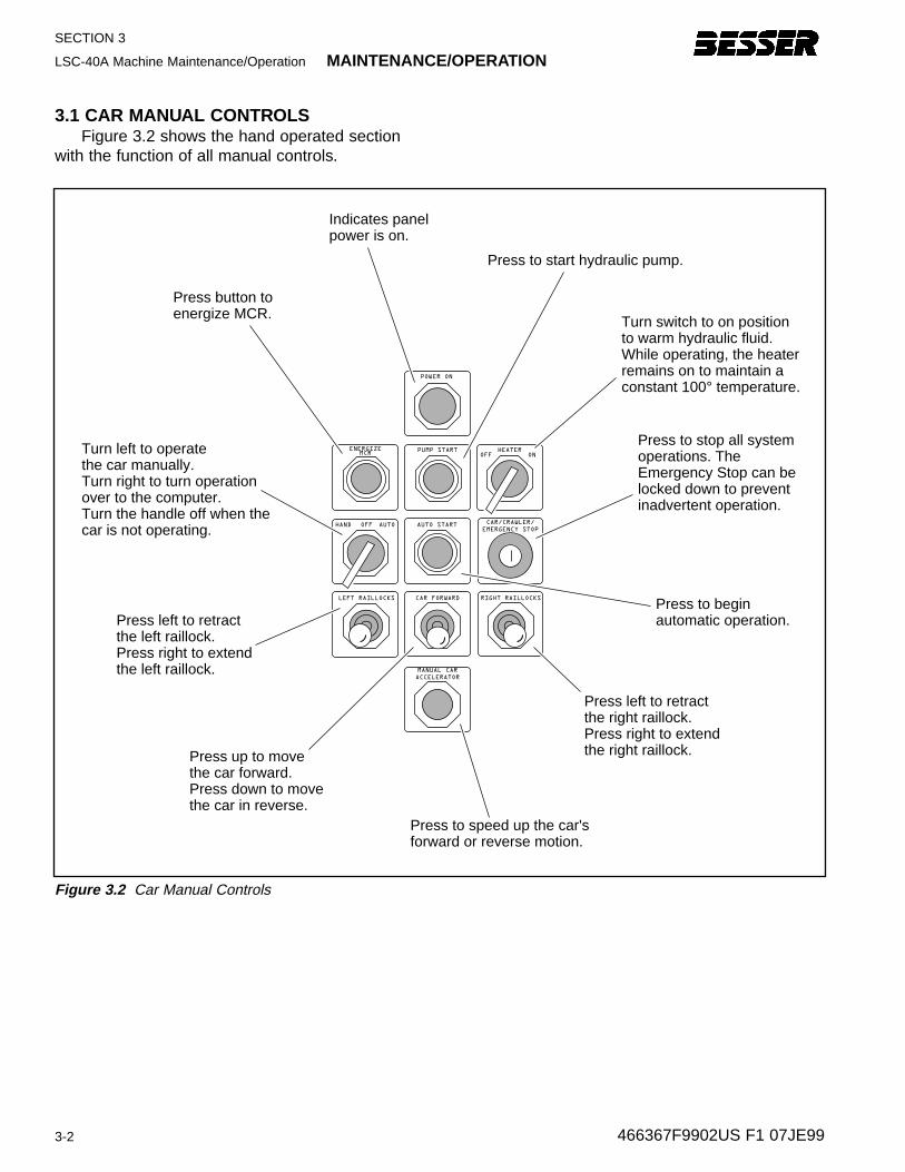
Figure 3.2 Car Manual Controls
3.1 CAR MANUAL CONTROLSFigure 3.2 shows the hand operated section
with the function of all manual controls.
MAINTENANCE/OPERATION LSC-40A Machine Maintenance/Operation
3-3
SECTION 3
466367F9902US F1 07JE99
Selects the new screen described above
Use arrows to move between choices in the information area
Deletesthe choice selected Arrow
confirms choice
Describes the programming area of the screen
Provides information to program for operation
LOCATION:
SEQUENCE:
LOADING KILN:
RACK COUNT:
UNLOADING KILN:
F1PROGRAM
CAR
F2RESET
RACK
ALARM
F3RAIL
LOCKS
ENABLED
F4CRAWLER
DIAG.
CENTER
F5KILN
MAP
F6INPUT/
OUTPUT
STATUS
F7 F8DATA
TABLE
DISPLAY
SENSOR
WIRING &
LOCATION
CAR INFORMATION:
OPERATOR ACTION:
OPERATOR MESSAGE CENTER
MAIN MENU
F9
F1
F10
F2
F11
F3
F12
F4
F13
F5
F14
F6
F15
F7
F16
F8
A
D
7
4
1
0. -
B
E
8
5
2
C
F
9
6
3
Describes theother screenchoices available
Instructs aboutoperator or caractions
AlphanumericKeypad
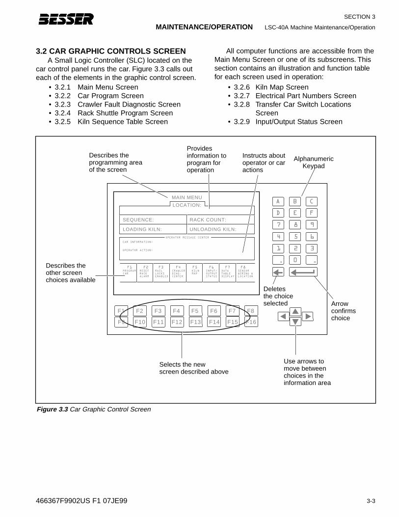
3.2 CAR GRAPHIC CONTROLS SCREENA Small Logic Controller (SLC) located on the
car control panel runs the car. Figure 3.3 calls outeach of the elements in the graphic control screen.
All computer functions are accessible from theMain Menu Screen or one of its subscreens. Thissection contains an illustration and function tablefor each screen used in operation:
• 3.2.1 Main Menu Screen• 3.2.2 Car Program Screen• 3.2.3 Crawler Fault Diagnostic Screen• 3.2.4 Rack Shuttle Program Screen• 3.2.5 Kiln Sequence Table Screen
• 3.2.6 Kiln Map Screen• 3.2.7 Electrical Part Numbers Screen• 3.2.8 Transfer Car Switch Locations
Screen• 3.2.9 Input/Output Status Screen
Figure 3.3 Car Graphic Control Screen
SECTION 3
LSC-40C Machine Maintenance/Operation MAINTENANCE/OPERATION
3-4 466367F9902US F1 07JE99
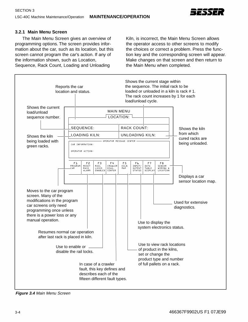
3.2.1 Main Men u ScreenThe Main Menu Screen gives an overview of
programming options. The screen provides infor-mation about the car, such as its location, but thisscreen cannot program the car’s action. If any ofthe information shown, such as Location,Sequence, Rack Count, Loading and Unloading
Kiln, is incorrect, the Main Menu Screen allowsthe operator access to other screens to modifythe choices or correct a problem. Press the func-tion key and the corresponding screen will appear.Make changes on that screen and then return tothe Main Menu when completed.
Figure 3.4 Main Menu Screen
In case of a crawlerfault, this key defines and describes each of the fifteen different fault types.
Moves to the car program screen. Many of themodifications in the program car screens only need programming once unless there is a power loss or any manual operation.
Used for extensivediagnostics.
Use to display the system electronics status.
Use to view rack locationsof product in the kilns, set or change the product type and number of full pallets on a rack.
Use to enable or disable the rail locks.
Reports the car location and status.
Shows the currentload/unload sequence number.
Shows the kiln being loaded with green racks.
Shows the current stage within the sequence. The initial rack to be loaded or unloaded in a kiln is rack # 1.The rack count increases by 1 for each load/unload cycle.
Shows the kilnfrom which cured racks are being unloaded.
Resumes normal car operationafter last rack is placed in kiln.
LOCATION:
SEQUENCE:
LOADING KILN:
RACK COUNT:
UNLOADING KILN:
CAR INFORMATION:
OPERATOR ACTION:
OPERATOR MESSAGE CENTER
MAIN MENU
Displays a car sensor location map.
F1PROGRAM
CAR
F2RESET
RACK
ALARM
F3RAIL
LOCKS
ENABLED
F4CRAWLER
DIAG.
CENTER
F5KILN
MAP
F6INPUT/
OUTPUT
STATUS
F7 F8DATA
TABLE
DISPLAY
SENSOR
WIRING &
LOCATION
MAINTENANCE/OPERATION LSC-40C Machine Maintenance/Operation
3-5
SECTION 3
466367F9902US F1 07JE99
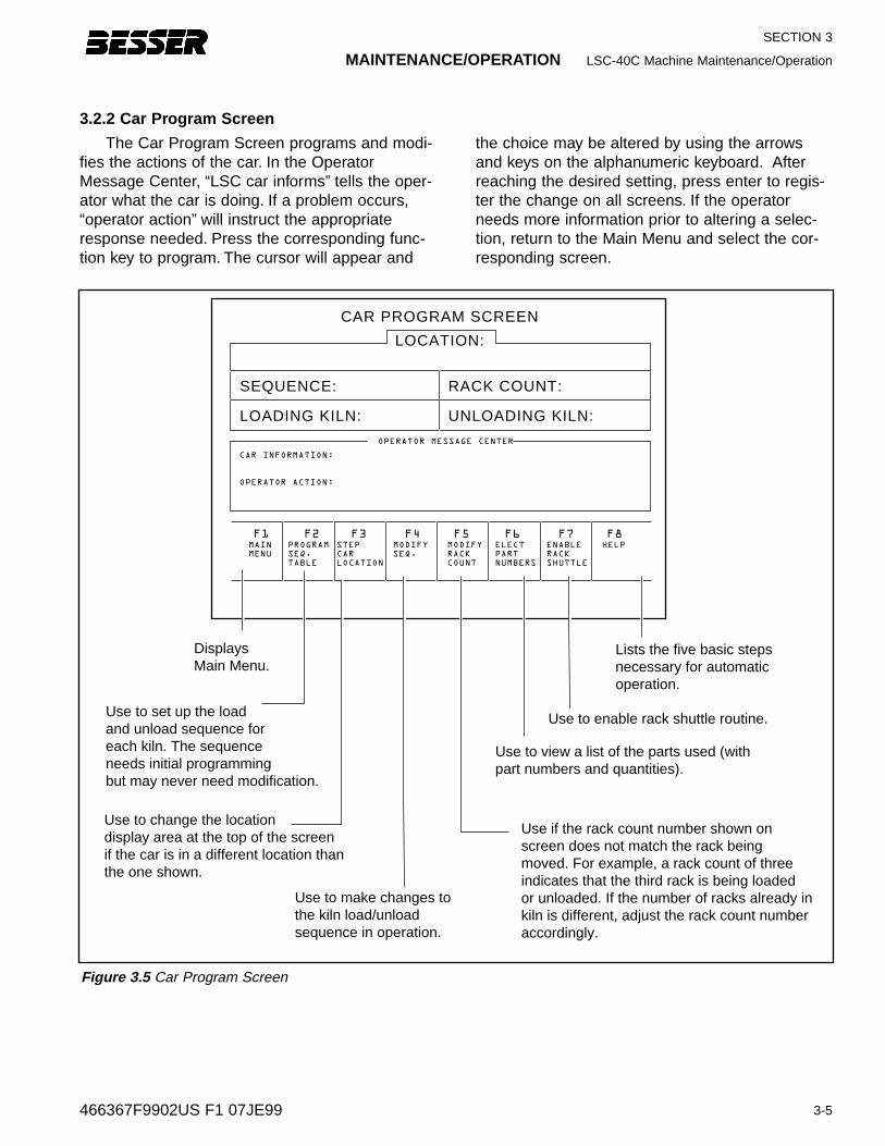
The Car Program Screen programs and modi-fies the actions of the car. In the OperatorMessage Center, “LSC car informs” tells the oper-ator what the car is doing. If a problem occurs,“operator action” will instruct the appropriateresponse needed. Press the corresponding func-tion key to program. The cursor will appear and
the choice may be altered by using the arrowsand keys on the alphanumeric keyboard. Afterreaching the desired setting, press enter to regis-ter the change on all screens. If the operatorneeds more information prior to altering a selec-tion, return to the Main Menu and select the cor-responding screen.
LOCATION:
SEQUENCE:
LOADING KILN:
RACK COUNT:
UNLOADING KILN:
F1MAIN
MENU
F2PROGRAM
SEQ.
TABLE
F3STEP
CAR
LOCATION
F4MODIFY
SEQ.
F5MODIFY
RACK
COUNT
F6ELECT
PART
NUMBERS
F7 F8ENABLE
RACK
SHUTTLE
HELP
CAR INFORMATION:
OPERATOR ACTION:
OPERATOR MESSAGE CENTER
CAR PROGRAM SCREEN
Use to make changes tothe kiln load/unload sequence in operation.
Displays Main Menu.
Use to set up the loadand unload sequence for each kiln. The sequence needs initial programming but may never need modification.
Use to enable rack shuttle routine.
Use to change the location display area at the top of the screenif the car is in a different location than the one shown.
Lists the five basic stepsnecessary for automatic operation.
Use if the rack count number shown onscreen does not match the rack beingmoved. For example, a rack count of three indicates that the third rack is being loadedor unloaded. If the number of racks already inkiln is different, adjust the rack count numberaccordingly.
Use to view a list of the parts used (withpart numbers and quantities).
3.2.2 Car Program Screen
Figure 3.5 Car Program Screen
SECTION 3
LSC-40C Machine Maintenance/Operation MAINTENANCE/OPERATION
3-6 466367F9902US F1 07JE99
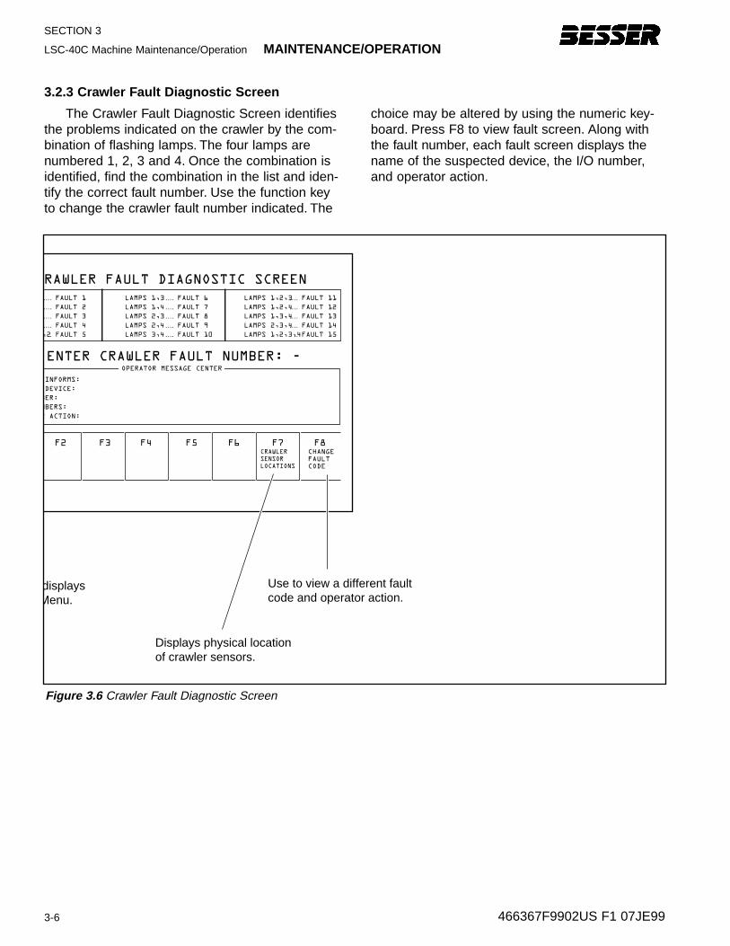
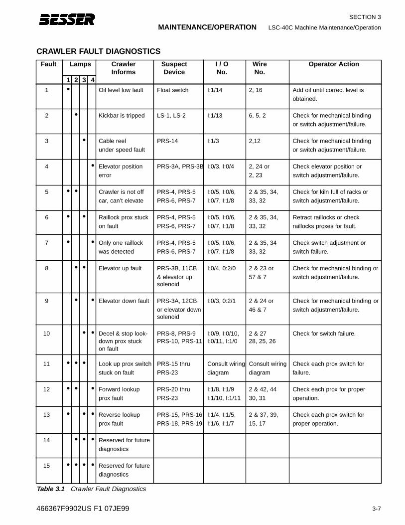
The Crawler Fault Diagnostic Screen identifiesthe problems indicated on the crawler by the com-bination of flashing lamps. The four lamps arenumbered 1, 2, 3 and 4. Once the combination isidentified, find the combination in the list and iden-tify the correct fault number. Use the function keyto change the crawler fault number indicated. The
choice may be altered by using the numeric key-board. Press F8 to view fault screen. Along withthe fault number, each fault screen displays thename of the suspected device, the I/O number,and operator action.
Figure 3.6 Crawler Fault Diagnostic Screen
3.2.3 Crawler F ault Dia gnostic Screen
ENTER CRAWLER FAULT NUMBER: -
F2 F3 F4 F5 F6 F7 F8CHANGE
FAULT
CODE
INFORMS:
DEVICE:
BER:
MBERS:
R ACTION:
OPERATOR MESSAGE CENTER
RAWLER FAULT DIAGNOSTIC SCREEN
,2
FAULT 1
FAULT 2
FAULT 3
FAULT 4
FAULT 5
....
....
....
....
..
LAMPS 1,3
LAMPS 1,4
LAMPS 2,3
LAMPS 2,4
LAMPS 3,4
FAULT 6
FAULT 7
FAULT 8
FAULT 9
FAULT 10
....
....
....
....
....
LAMPS 1,2,3
LAMPS 1,2,4
LAMPS 1,3,4
LAMPS 2,3,4
LAMPS 1,2,3,4
FAULT 11
FAULT 12
FAULT 13
FAULT 14
FAULT 15
....
....
....
....
..
displays Menu.
Use to view a different faultcode and operator action.
CRAWLER
SENSOR
LOCATIONS
Displays physical locationof crawler sensors.
3-7
SECTION 3
466367F9902US F1 07JE99
Fault Lamps Crawler Suspect I / O Wire Operator ActionInforms Device No. No.
1 2 3 41 • Oil level low fault Float switch I:1/14 2, 16 Add oil until correct level is
obtained.
2 • Kickbar is tripped LS-1, LS-2 I:1/13 6, 5, 2 Check for mechanical binding
or switch adjustment/failure.
3 • Cable reel PRS-14 I:1/3 2,12 Check for mechanical binding
under speed fault or switch adjustment/failure.
4 • Elevator position PRS-3A, PRS-3B I:0/3, I:0/4 2, 24 or Check elevator position or
error 2, 23 switch adjustment/failure.
5 • • Crawler is not off PRS-4, PRS-5 I:0/5, I:0/6, 2 & 35, 34, Check for kiln full of racks or
car, can’t elevate PRS-6, PRS-7 I:0/7, I:1/8 33, 32 switch adjustment/failure.
6 • • Raillock prox stuck PRS-4, PRS-5 I:0/5, I:0/6, 2 & 35, 34, Retract raillocks or check
on fault PRS-6, PRS-7 I:0/7, I:1/8 33, 32 raillocks proxes for fault.
7 • • Only one raillock PRS-4, PRS-5 I:0/5, I:0/6, 2 & 35, 34 Check switch adjustment or
was detected PRS-6, PRS-7 I:0/7, I:1/8 33, 32 switch failure.
8 • • Elevator up fault PRS-3B, 11CB I:0/4, 0:2/0 2 & 23 or Check for mechanical binding or
& elevator up 57 & 7 switch adjustment/failure.solenoid
9 • • Elevator down fault PRS-3A, 12CB I:0/3, 0:2/1 2 & 24 or Check for mechanical binding or
or elevator down 46 & 7 switch adjustment/failure.solenoid
10 • • Decel & stop look- PRS-8, PRS-9 I:0/9, I:0/10, 2 & 27 Check for switch failure.down prox stuck PRS-10, PRS-11 I:0/11, I:1/0 28, 25, 26on fault
11 • • • Look up prox switch PRS-15 thru Consult wiring Consult wiring Check each prox switch for
stuck on fault PRS-23 diagram diagram failure.
12 • • • Forward lookup PRS-20 thru I:1/8, I:1/9 2 & 42, 44 Check each prox for proper
prox fault PRS-23 I:1/10, I:1/11 30, 31 operation.
13 • • • Reverse lookup PRS-15, PRS-16 I:1/4, I:1/5, 2 & 37, 39, Check each prox switch for
prox fault PRS-18, PRS-19 I:1/6, I:1/7 15, 17 proper operation.
14 • • • Reserved for future
diagnostics
15 • • • • Reserved for future
diagnostics
CRAWLER FAULT DIAGNOSTICS
Table 3.1 Crawler Fault Diagnostics
MAINTENANCE/OPERATION LSC-40C Machine Maintenance/Operation
SECTION 3
LSC-40C Machine Maintenance/Operation MAINTENANCE/OPERATION
3-8 466367F9902US F1 07JE99
3.2.4 Rack Shuttle Main Men u Screen
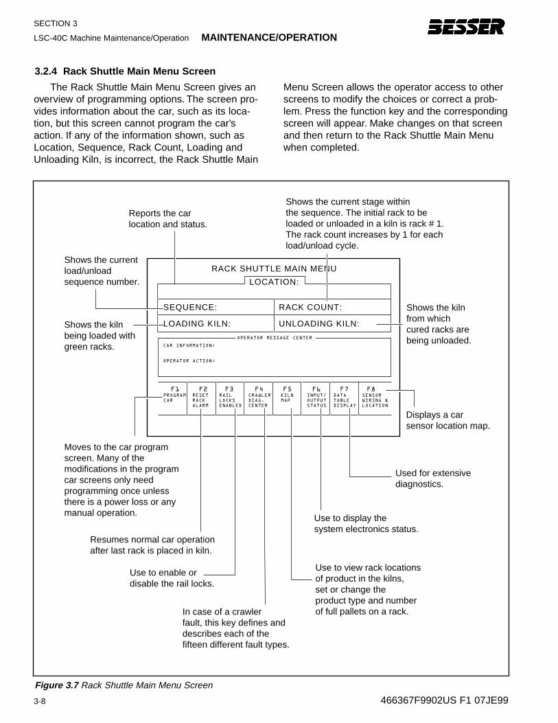
The Rack Shuttle Main Menu Screen gives anoverview of programming options. The screen pro-vides information about the car, such as its loca-tion, but this screen cannot program the car’saction. If any of the information shown, such asLocation, Sequence, Rack Count, Loading andUnloading Kiln, is incorrect, the Rack Shuttle Main
Menu Screen allows the operator access to otherscreens to modify the choices or correct a prob-lem. Press the function key and the correspondingscreen will appear. Make changes on that screenand then return to the Rack Shuttle Main Menuwhen completed.
LOCATION:
SEQUENCE:
LOADING KILN:
RACK COUNT:
UNLOADING KILN:
F1PROGRAM
CAR
F2RESET
RACK
ALARM
F3RAIL
LOCKS
ENABLED
F4CRAWLER
DIAG.
CENTER
F5KILN
MAP
F6INPUT/
OUTPUT
STATUS
F7 F8DATA
TABLE
DISPLAY
SENSOR
WIRING &
LOCATION
CAR INFORMATION:
OPERATOR ACTION:
OPERATOR MESSAGE CENTER
RACK SHUTTLE MAIN MENU
In case of a crawlerfault, this key defines and describes each of the fifteen different fault types.
Moves to the car program screen. Many of themodifications in the program car screens only need programming once unless there is a power loss or any manual operation.
Used for extensivediagnostics.
Use to display the system electronics status.
Use to view rack locationsof product in the kilns, set or change the product type and number of full pallets on a rack.
Use to enable or disable the rail locks.
Reports the car location and status.
Shows the currentload/unload sequence number.
Shows the kiln being loaded with green racks.
Shows the current stage within the sequence. The initial rack to be loaded or unloaded in a kiln is rack # 1.The rack count increases by 1 for each load/unload cycle.
Shows the kilnfrom which cured racks are being unloaded.
Resumes normal car operationafter last rack is placed in kiln.
Displays a car sensor location map.
Figure 3.7 Rack Shuttle Main Menu Screen
MAINTENANCE/OPERATION LSC-40C Machine Maintenance/Operation
3-9
SECTION 3
466367F9902US F1 07JE99
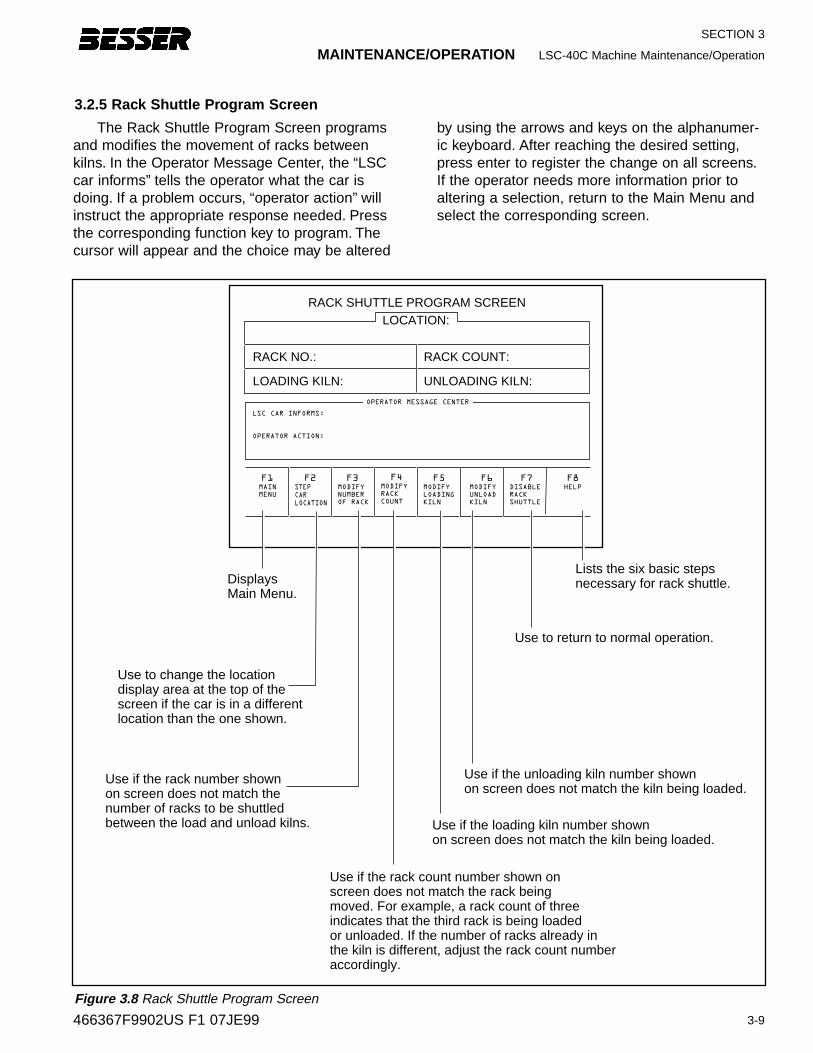
3.2.5 Rack Shuttle Pr ogram Screen
The Rack Shuttle Program Screen programsand modifies the movement of racks betweenkilns. In the Operator Message Center, the “LSCcar informs” tells the operator what the car isdoing. If a problem occurs, “operator action” willinstruct the appropriate response needed. Pressthe corresponding function key to program. Thecursor will appear and the choice may be altered
by using the arrows and keys on the alphanumer-ic keyboard. After reaching the desired setting,press enter to register the change on all screens.If the operator needs more information prior toaltering a selection, return to the Main Menu andselect the corresponding screen.
Use if the rack number shownon screen does not match thenumber of racks to be shuttled between the load and unload kilns.
Displays Main Menu.
Use to return to normal operation.
Use to change the location display area at the top of the screen if the car is in a different location than the one shown.
Lists the six basic stepsnecessary for rack shuttle.
LOCATION:
RACK NO.:
LOADING KILN:
RACK COUNT:
UNLOADING KILN:
F1MAIN
MENU
F2 F3MODIFY
NUMBER
OF RACK
F4MODIFY
RACK
COUNT
F5MODIFY
LOADING
KILN
F6MODIFY
UNLOAD
KILN
F7 F8DISABLE
RACK
SHUTTLE
HELP
LSC CAR INFORMS:
OPERATOR ACTION:
OPERATOR MESSAGE CENTER
RACK SHUTTLE PROGRAM SCREEN
STEP
CAR
LOCATION
Use if the rack count number shown onscreen does not match the rack beingmoved. For example, a rack count of three indicates that the third rack is being loadedor unloaded. If the number of racks already inthe kiln is different, adjust the rack count numberaccordingly.
Use if the loading kiln number shown on screen does not match the kiln being loaded.
Use if the unloading kiln number shown on screen does not match the kiln being loaded.
Figure 3.8 Rack Shuttle Program Screen
SECTION 3
LSC-40C Machine Maintenance/Operation MAINTENANCE/OPERATION
3-10 466367F9902US F1 07JE99
F1MAIN
MENU
MODIFY
SEQ.
TABLE
F2 F3 F4 F5 F6 F7 F8
KILN SEQUENCE TABLE
SEQUENCE
NUMBER
01
02
03
04
05
06
07
08
09
10
11
12
LOAD
KILN
01
02
03
04
05
06
07
08
09
10
00
00
UNLOAD
KILN
02
03
04
05
06
07
08
09
10
01
00
00
SEQUENCE
NUMBER
13
14
15
16
17
18
19
20
21
22
23
24
LOAD
KILN
00
00
00
00
00
00
00
00
00
00
00
00
UNLOAD
KILN
00
00
00
00
00
00
00
00
00
00
00
00
Displays the Main Menu.
Use to change any of the kiln numbers in the table.
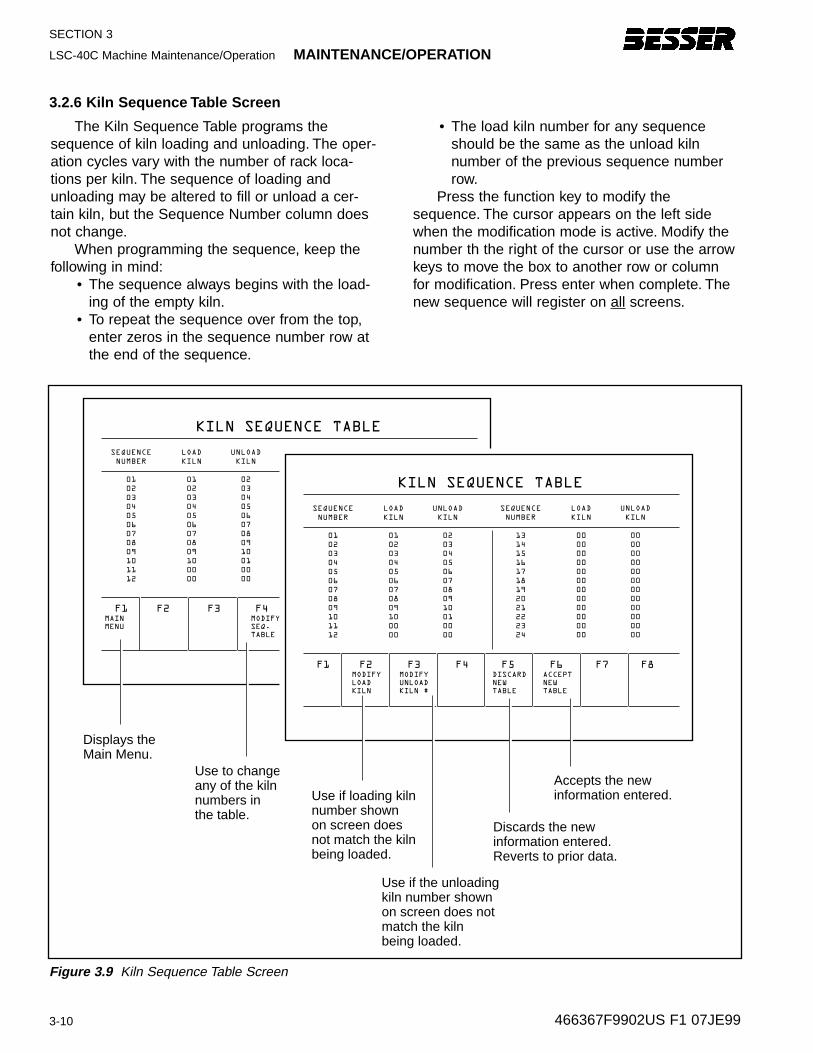
The Kiln Sequence Table programs thesequence of kiln loading and unloading. The oper-ation cycles vary with the number of rack loca-tions per kiln. The sequence of loading andunloading may be altered to fill or unload a cer-tain kiln, but the Sequence Number column doesnot change.
When programming the sequence, keep thefollowing in mind:
• The sequence always begins with the load-ing of the empty kiln.
• To repeat the sequence over from the top,enter zeros in the sequence number row atthe end of the sequence.
• The load kiln number for any sequenceshould be the same as the unload kiln number of the previous sequence numberrow.
Press the function key to modify thesequence. The cursor appears on the left sidewhen the modification mode is active. Modify thenumber th the right of the cursor or use the arrowkeys to move the box to another row or columnfor modification. Press enter when complete. Thenew sequence will register on all screens.
3.2.6 Kiln Sequence Table Screen
F1MODIFY
LOAD
KILN
MODIFY
UNLOAD
KILN #
ACCEPT
NEW
TABLE
DISCARD
NEW
TABLE
F2 F3 F4 F5 F6 F7 F8
KILN SEQUENCE TABLE
SEQUENCE
NUMBER
01
02
03
04
05
06
07
08
09
10
11
12
LOAD
KILN
01
02
03
04
05
06
07
08
09
10
00
00
UNLOAD
KILN
02
03
04
05
06
07
08
09
10
01
00
00
SEQUENCE
NUMBER
13
14
15
16
17
18
19
20
21
22
23
24
LOAD
KILN
00
00
00
00
00
00
00
00
00
00
00
00
UNLOAD
KILN
00
00
00
00
00
00
00
00
00
00
00
00
Use if loading kiln number shownon screen does not match the kiln being loaded.
Discards the new information entered.Reverts to prior data.
Use if the unloading kiln number shownon screen does not match the kiln being loaded.
Accepts the newinformation entered.
Figure 3.9 Kiln Sequence Table Screen
MAINTENANCE/OPERATION LSC-40C Machine Maintenance/Operation
3-11
SECTION 3
466367F9902US F1 07JE99
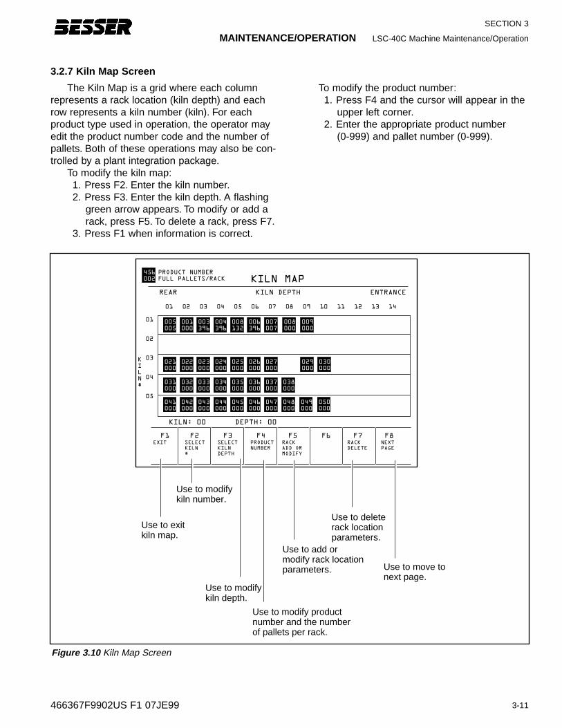
3.2.7 Kiln Map Screen
The Kiln Map is a grid where each columnrepresents a rack location (kiln depth) and eachrow represents a kiln number (kiln). For eachproduct type used in operation, the operator mayedit the product number code and the number ofpallets. Both of these operations may also be con-trolled by a plant integration package.
To modify the kiln map:1. Press F2. Enter the kiln number.2. Press F3. Enter the kiln depth. A flashing
green arrow appears. To modify or add arack, press F5. To delete a rack, press F7.
3. Press F1 when information is correct.
To modify the product number:1. Press F4 and the cursor will appear in the
upper left corner.2. Enter the appropriate product number
(0-999) and pallet number (0-999).
01 02 03 04 05 06 07 08 09 10 11 12 13 14
KILN MAP
REAR KILN DEPTH ENTRANCE
01
02
03
04
05
456
002
PRODUCT NUMBER
FULL PALLETS/RACK
005
005
021
000
031
000
041
000
001
000
022
000
032
000
042
000
003
396
023
000
033
000
043
000
004
396
024
000
034
000
044
000
008
132
025
000
035
000
045
000
006
396
026
000
036
000
046
000
007
007
008
000
009
000
027
000
029
000
030
000
037
000
038
000
047
000
048
000
049
000
050
000
K
I
L
N
#
F1SELECT
KILN
#
SELECT
KILN
DEPTH
PRODUCT
NUMBER
RACK
ADD OR
MODIFY
RACK
DELETE
NEXT
PAGE
F2 F3 F4 F5 F6 F7 F8
Use to modify kiln number.
Use to add ormodify rack locationparameters.
EXIT
KILN: 00 DEPTH: 00
Use to exitkiln map.
Use to modifykiln depth.
Use to modify product number and the number of pallets per rack.
Use to deleterack locationparameters.
Use to move to next page.
Figure 3.10 Kiln Map Screen
SECTION 3
LSC-40C Machine Maintenance/Operation MAINTENANCE/OPERATION
3-12 466367F9902US F1 07JE99
Figure 3.11 Electrical Part Numbers Screen
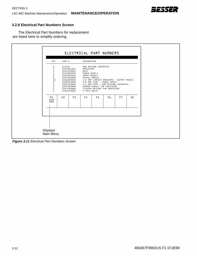
3.2.8 Electrical P art Number s Screen
F1MAIN
MENU
F2 F3 F4 F5 F6 F7 F8
ELECTRICAL PART NUMBERS
1
1
1
1
2
2
13
1
1
1
1
1
114763
113773FL524
113772F00A7
113772F00P2
113772FIA16
113772F00A8
113118F0012
112974F1030
112974F0015
113773F00M2
113773F00BA
113115F0003
MAN MACHINE INTERFACE
PROCESSOR
RACK
POWER SUPPLY
INPUT MODULE
OUTPUT MODULE
1.2 AMP CIRCUIT BREAKERS - OUTPUT MODULE
3.0 AMP FUSE - POWER SUPPLY
1.5 AMP FUSE - MAN MACHINE INTERFACE
EEPROM MODULE FOR PROCESSOR
LITHIUM BATTERY FOR PROCESSOR
4 POLE RELAY
QTY PART # DESCRIPTION
Displays Main Menu.
The Electrical Part Numbers for replacementare listed here to simplify ordering.
MAINTENANCE/OPERATION LSC-40C Machine Maintenance/Operation
3-13
SECTION 3
466367F9902US F1 07JE99
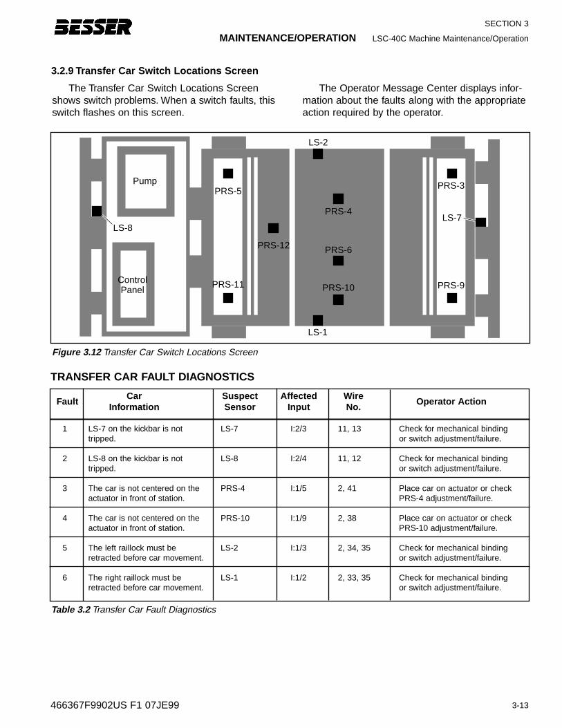
3.2.9 Transf er Car Switc h Locations Screen
Pump
LS-8
PRS-11
PRS-5
PRS-12
LS-2
PRS-4
PRS-3
PRS-9
LS-7
PRS-6
PRS-10
LS-1
ControlPanel
Figure 3.12 Transfer Car Switch Locations Screen
The Transfer Car Switch Locations Screenshows switch problems. When a switch faults, thisswitch flashes on this screen.
The Operator Message Center displays infor-mation about the faults along with the appropriateaction required by the operator.
FaultCar Suspect Aff ected Wire
Operator ActionInformation Sensor Input No.
1 LS-7 on the kickbar is not LS-7 I:2/3 11, 13 Check for mechanical bindingtripped. or switch adjustment/failure.
2 LS-8 on the kickbar is not LS-8 I:2/4 11, 12 Check for mechanical bindingtripped. or switch adjustment/failure.
3 The car is not centered on the PRS-4 I:1/5 2, 41 Place car on actuator or checkactuator in front of station. PRS-4 adjustment/failure.
4 The car is not centered on the PRS-10 I:1/9 2, 38 Place car on actuator or checkactuator in front of station. PRS-10 adjustment/failure.
5 The left raillock must be LS-2 I:1/3 2, 34, 35 Check for mechanical bindingretracted before car movement. or switch adjustment/failure.
6 The right raillock must be LS-1 I:1/2 2, 33, 35 Check for mechanical bindingretracted before car movement. or switch adjustment/failure.
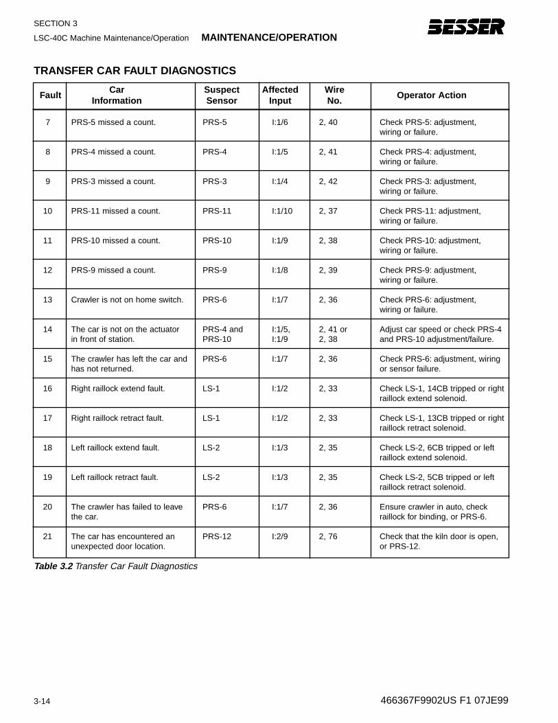
TRANSFER CAR FAULT DIAGNOSTICS
Table 3.2 Transfer Car Fault Diagnostics
SECTION 3
LSC-40C Machine Maintenance/Operation MAINTENANCE/OPERATION
3-14 466367F9902US F1 07JE99
FaultCar Suspect Aff ected Wire
Operator ActionInformation Sensor Input No.
7 PRS-5 missed a count. PRS-5 I:1/6 2, 40 Check PRS-5: adjustment,wiring or failure.
8 PRS-4 missed a count. PRS-4 I:1/5 2, 41 Check PRS-4: adjustment,wiring or failure.
9 PRS-3 missed a count. PRS-3 I:1/4 2, 42 Check PRS-3: adjustment,wiring or failure.
10 PRS-11 missed a count. PRS-11 I:1/10 2, 37 Check PRS-11: adjustment,wiring or failure.
11 PRS-10 missed a count. PRS-10 I:1/9 2, 38 Check PRS-10: adjustment,wiring or failure.
12 PRS-9 missed a count. PRS-9 I:1/8 2, 39 Check PRS-9: adjustment,wiring or failure.
13 Crawler is not on home switch. PRS-6 I:1/7 2, 36 Check PRS-6: adjustment,wiring or failure.
14 The car is not on the actuator PRS-4 and I:1/5, 2, 41 or Adjust car speed or check PRS-4in front of station. PRS-10 I:1/9 2, 38 and PRS-10 adjustment/failure.
15 The crawler has left the car and PRS-6 I:1/7 2, 36 Check PRS-6: adjustment, wiringhas not returned. or sensor failure.
16 Right raillock extend fault. LS-1 I:1/2 2, 33 Check LS-1, 14CB tripped or rightraillock extend solenoid.
17 Right raillock retract fault. LS-1 I:1/2 2, 33 Check LS-1, 13CB tripped or rightraillock retract solenoid.
18 Left raillock extend fault. LS-2 I:1/3 2, 35 Check LS-2, 6CB tripped or leftraillock extend solenoid.
19 Left raillock retract fault. LS-2 I:1/3 2, 35 Check LS-2, 5CB tripped or leftraillock retract solenoid.
20 The crawler has failed to leave PRS-6 I:1/7 2, 36 Ensure crawler in auto, checkthe car. raillock for binding, or PRS-6.
21 The car has encountered an PRS-12 I:2/9 2, 76 Check that the kiln door is open,unexpected door location. or PRS-12.
TRANSFER CAR FAULT DIAGNOSTICS
Table 3.2 Transfer Car Fault Diagnostics
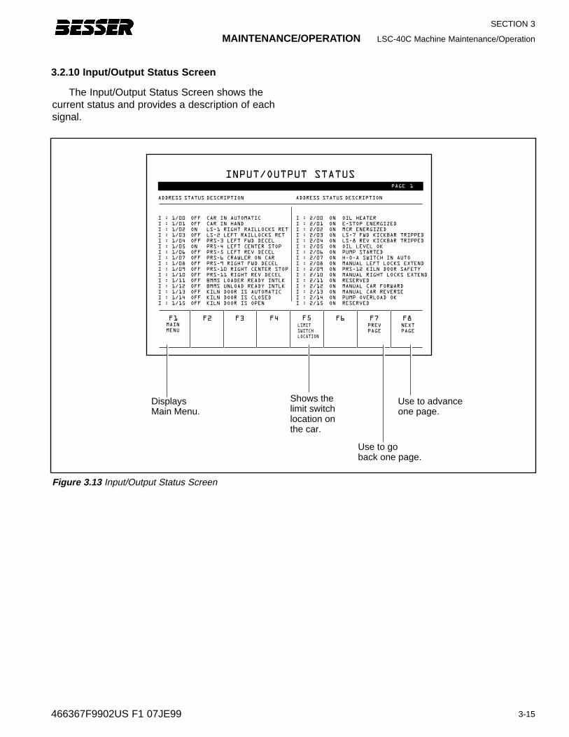
MAINTENANCE/OPERATION LSC-40C Machine Maintenance/Operation
3-15
SECTION 3
466367F9902US F1 07JE99
The Input/Output Status Screen shows thecurrent status and provides a description of eachsignal.
Figure 3.13 Input/Output Status Screen
3.2.10 Input/Output Status Screen
F1MAIN
MENULIMIT
SWITCH
LOCATION
NEXT
PAGE
PREV
PAGE
F2 F3 F4 F5 F6 F7 F8
INPUT/OUTPUT STATUS
ADDRESS STATUS DESCRIPTION
PAGE 1
I : 1/00
I : 1/01
I : 1/02
I : 1/03
I : 1/04
I : 1/05
I : 1/06
I : 1/07
I : 1/08
I : 1/09
I : 1/10
I : 1/11
I : 1/12
I : 1/13
I : 1/14
I : 1/15
OFF
OFF
ON
OFF
OFF
ON
OFF
OFF
OFF
OFF
OFF
OFF
OFF
OFF
OFF
OFF
CAR IN AUTOMATIC
CAR IN HAND
LS-1 RIGHT RAILLOCKS RET
LS-2 LEFT RAILLOCKS RET
PRS-3 LEFT FWD DECEL
PRS-4 LEFT CENTER STOP
PRS-5 LEFT REV DECEL
PRS-6 CRAWLER ON CAR
PRS-9 RIGHT FWD DECEL
PRS-10 RIGHT CENTER STOP
PRS-11 RIGHT REV DECEL
BMMS LOADER READY INTLK
BMMS UNLOAD READY INTLK
KILN DOOR IS AUTOMATIC
KILN DOOR IS CLOSED
KILN DOOR IS OPEN
ADDRESS STATUS DESCRIPTION
I : 2/00
I : 2/01
I : 2/02
I : 2/03
I : 2/04
I : 2/05
I : 2/06
I : 2/07
I : 2/08
I : 2/09
I : 2/10
I : 2/11
I : 2/12
I : 2/13
I : 2/14
I : 2/15
ON
ON
ON
ON
ON
ON
ON
ON
ON
ON
ON
ON
ON
ON
ON
ON
OIL HEATER
E-STOP ENERGIZED
MCR ENERGIZED
LS-7 FWD KICKBAR TRIPPED
LS-8 REV KICKBAR TRIPPED
OIL LEVEL OK
PUMP STARTED
H-O-A SWITCH IN AUTO
MANUAL LEFT LOCKS EXTEND
PRS-12 KILN DOOR SAFETY
MANUAL RIGHT LOCKS EXTEND
RESERVED
MANUAL CAR FORWARD
MANUAL CAR REVERSE
PUMP OVERLOAD OK
RESERVED
Displays Main Menu.
Shows the limit switchlocation onthe car.
Use to go back one page.
Use to advance one page.
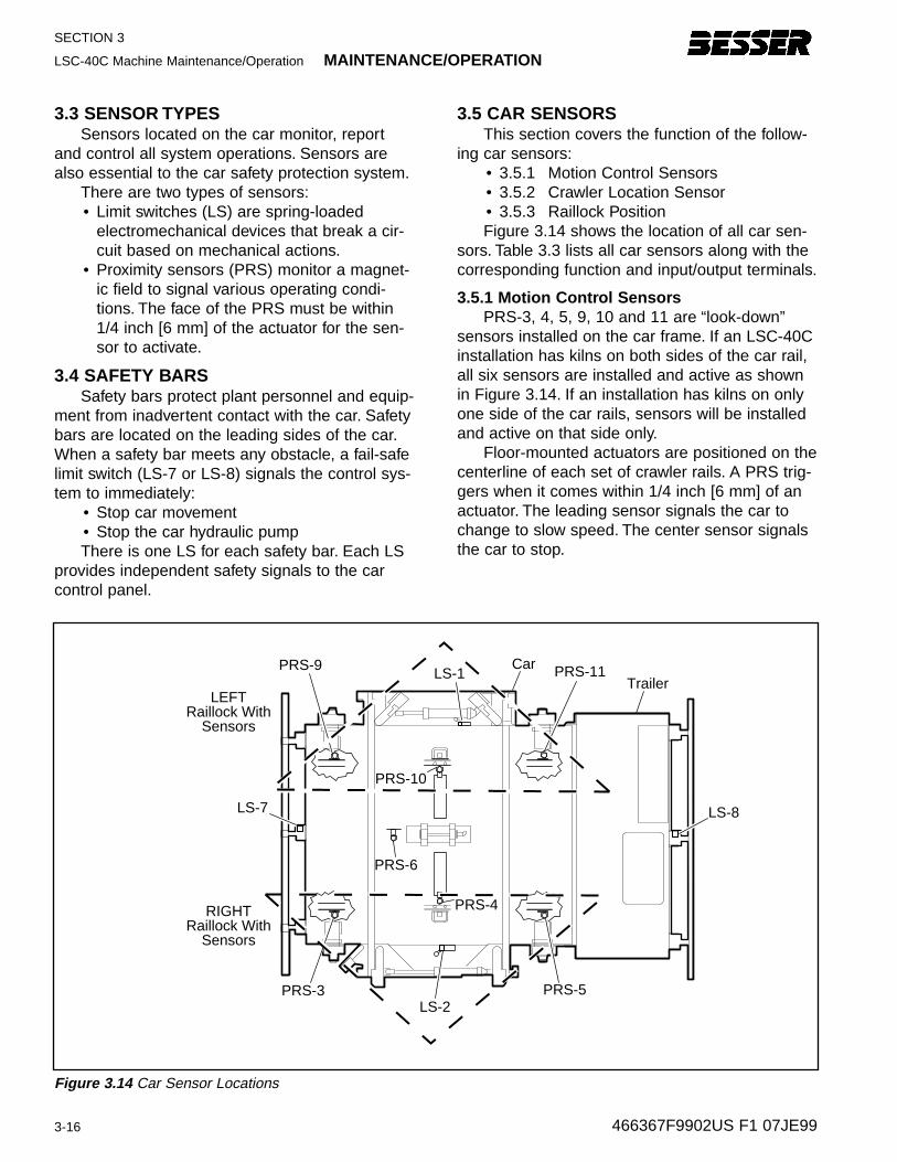
SECTION 3
LSC-40C Machine Maintenance/Operation MAINTENANCE/OPERATION
3-16 466367F9902US F1 07JE99
3.3 SENSOR TYPESSensors located on the car monitor, report
and control all system operations. Sensors arealso essential to the car safety protection system.
There are two types of sensors:• Limit switches (LS) are spring-loaded
electromechanical devices that break a cir-cuit based on mechanical actions.
• Proximity sensors (PRS) monitor a magnet-ic field to signal various operating condi-tions. The face of the PRS must be within1/4 inch [6 mm] of the actuator for the sen-sor to activate.
3.4 SAFETY BARSSafety bars protect plant personnel and equip-
ment from inadvertent contact with the car. Safetybars are located on the leading sides of the car.When a safety bar meets any obstacle, a fail-safelimit switch (LS-7 or LS-8) signals the control sys-tem to immediately:
• Stop car movement• Stop the car hydraulic pumpThere is one LS for each safety bar. Each LS
provides independent safety signals to the carcontrol panel.
3.5 CAR SENSORSThis section covers the function of the follow-
ing car sensors:• 3.5.1 Motion Control Sensors• 3.5.2 Crawler Location Sensor• 3.5.3 Raillock PositionFigure 3.14 shows the location of all car sen-
sors. Table 3.3 lists all car sensors along with thecorresponding function and input/output terminals.
3.5.1 Motion Contr ol Sensor sPRS-3, 4, 5, 9, 10 and 11 are “look-down”
sensors installed on the car frame. If an LSC-40Cinstallation has kilns on both sides of the car rail,all six sensors are installed and active as shownin Figure 3.14. If an installation has kilns on onlyone side of the car rails, sensors will be installedand active on that side only.
Floor-mounted actuators are positioned on thecenterline of each set of crawler rails. A PRS trig-gers when it comes within 1/4 inch [6 mm] of anactuator. The leading sensor signals the car tochange to slow speed. The center sensor signalsthe car to stop.
PRS-9
LEFTRaillock With
Sensors
RIGHTRaillock With
Sensors
PRS-10
LS-1
PRS-6
PRS-4
LS-2
PRS-11
LS-8LS-7
PRS-3 PRS-5
CarTrailer
Figure 3.14 Car Sensor Locations
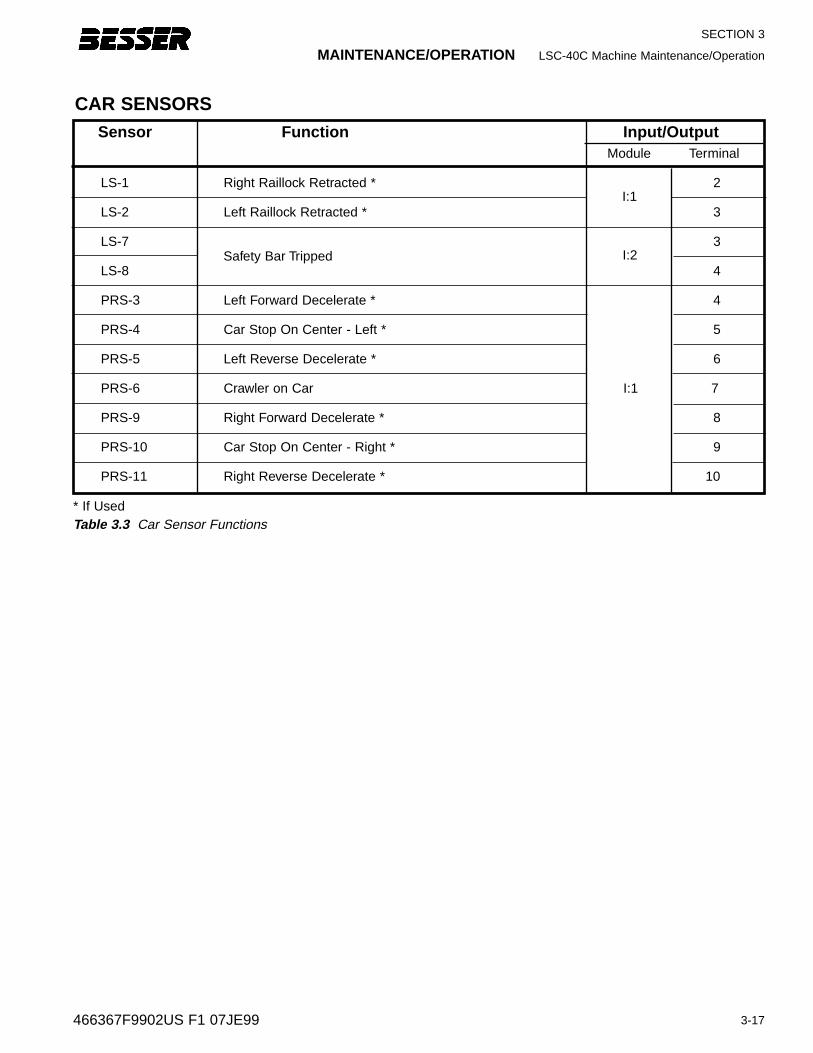
MAINTENANCE/OPERATION LSC-40C Machine Maintenance/Operation
3-17
SECTION 3
466367F9902US F1 07JE99
Sensor Function Input/OutputModule Terminal
LS-1 Right Raillock Retracted * 2
LS-2 Left Raillock Retracted * 3
LS-7 3
LS-8 4
PRS-3 Left Forward Decelerate * 4
PRS-4 Car Stop On Center - Left * 5
PRS-5 Left Reverse Decelerate * 6
PRS-6 Crawler on Car I:1 7
PRS-9 Right Forward Decelerate * 8
PRS-10 Car Stop On Center - Right * 9
PRS-11 Right Reverse Decelerate * 10
CAR SENSORS
* If UsedTable 3.3 Car Sensor Functions
Safety Bar Tripped
I:1
I:2
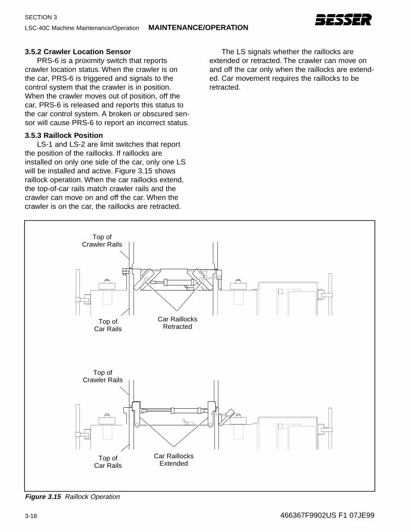
SECTION 3
LSC-40C Machine Maintenance/Operation MAINTENANCE/OPERATION
3-18 466367F9902US F1 07JE99
3.5.2 Crawler Location SensorPRS-6 is a proximity switch that reports
crawler location status. When the crawler is onthe car, PRS-6 is triggered and signals to thecontrol system that the crawler is in position.When the crawler moves out of position, off thecar, PRS-6 is released and reports this status tothe car control system. A broken or obscured sen-sor will cause PRS-6 to report an incorrect status.
3.5.3 Railloc k PositionLS-1 and LS-2 are limit switches that report
the position of the raillocks. If raillocks areinstalled on only one side of the car, only one LSwill be installed and active. Figure 3.15 showsraillock operation. When the car raillocks extend,the top-of-car rails match crawler rails and thecrawler can move on and off the car. When thecrawler is on the car, the raillocks are retracted.
The LS signals whether the raillocks areextended or retracted. The crawler can move onand off the car only when the raillocks are extend-ed. Car movement requires the raillocks to beretracted.
Top ofCrawler Rails
Top ofCrawler Rails
Car RaillocksExtended
Car RaillocksRetracted
Top ofCar Rails
Top ofCar Rails
Figure 3.15 Raillock Operation
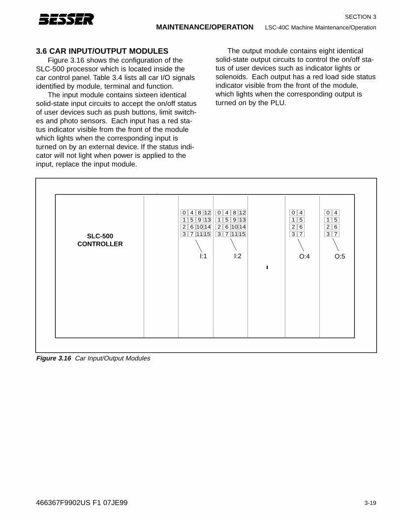
MAINTENANCE/OPERATION LSC-40C Machine Maintenance/Operation
3-19
SECTION 3
466367F9902US F1 07JE99
3.6 CAR INPUT/OUTPUT MODULESFigure 3.16 shows the configuration of the
SLC-500 processor which is located inside thecar control panel. Table 3.4 lists all car I/O signalsidentified by module, terminal and function.
The input module contains sixteen identicalsolid-state input circuits to accept the on/off statusof user devices such as push buttons, limit switch-es and photo sensors. Each input has a red sta-tus indicator visible from the front of the modulewhich lights when the corresponding input isturned on by an external device. If the status indi-cator will not light when power is applied to theinput, replace the input module.
-
0
SLC-500 CONTROLLER
4 8 121 5 9 132 6 10 143 7 11 15
0 4 8 121 5 9 132 6 10 143 7 11 15
0 41 52 63 7
0 41 52 63 7
I:1 I:2 O:4 O:5
Figure 3.16 Car Input/Output Modules
The output module contains eight identicalsolid-state output circuits to control the on/off sta-tus of user devices such as indicator lights orsolenoids. Each output has a red load side statusindicator visible from the front of the module,which lights when the corresponding output isturned on by the PLU.
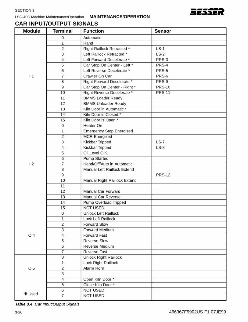
SECTION 3
LSC-40C Machine Maintenance/Operation MAINTENANCE/OPERATION
3-20 466367F9902US F1 07JE99
CAR INPUT/OUTPUT SIGNALSModule Terminal Function Sensor
0 Automatic1 Hand2 Right Raillock Retracted * LS-13 Left Raillock Retracted * LS-24 Left Forward Decelerate * PRS-35 Car Stop On Center - Left * PRS-46 Left Reverse Decelerate * PRS-5
I:1 7 Crawler On Car PRS-68 Right Forward Decelerate * PRS-99 Car Stop On Center - Right * PRS-10
10 Right Reverse Decelerate * PRS-1111 BMMS Loader Ready 12 BMMS Unloader Ready 13 Kiln Door in Automatic *14 Kiln Door is Closed *15 Kiln Door is Open *0 Heater On1 Emergency Stop Energized2 MCR Energized3 Kickbar Tripped LS-74 Kickbar Tripped LS-85 Oil Level O.K.6 Pump Started
I:2 7 Hand/Off/Auto in Automatic8 Manual Left Raillock Extend9 PRS-12
10 Manual Right Raillock Extend1112 Manual Car Forward13 Manual Car Reverse14 Pump Overload Tripped15 NOT USED0 Unlock Left Raillock1 Lock Left Raillock2 Forward Slow3 Forward Medium
O:4 4 Forward Fast5 Reverse Slow6 Reverse Medium7 Reverse Fast0 Unlock Right Raillock1 Lock Right Raillock
O:5 2 Alarm Horn34 Open Kiln Door *5 Close Kiln Door *6 NOT USED7 NOT USED*If Used
Table 3.4 Car Input/Output Signals
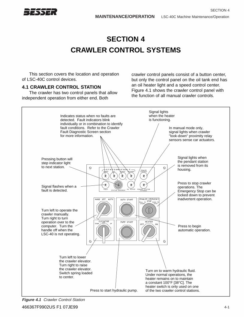
MAINTENANCE/OPERATION LSC-40C Machine Maintenance/Operation
4-1
SECTION 4
466367F9902US F1 07JE99
This section covers the location and operationof LSC-40C control devices.
4.1 CRAWLER CONTROL STATIONThe crawler has two control panels that allow
independent operation from either end. Both
crawler control panels consist of a button center,but only the control panel on the oil tank end hasan oil heater light and a speed control center.Figure 4.1 shows the crawler control panel withthe function of all manual crawler controls.
SECTION 4
CRAWLER CONTROL SYSTEMS
LOADER
1
R R R
G
R R
R R R
2 3 4
STATION/FAULT
FAULTSTATION INCREMENT
KILN STORAGE UNLOADERCRAWLER
CENTERED
PENDANT STATION
EXTENDED
OIL HEATER
AUTO START CRAWLER EMERGENCY
STOPPULL TO
START
PUSH TO
STOP
HAND OFF AUTO
PUMP STARTDOWN UP
ELEVATOR
OFF
HEATER
ON
Press to stop crawleroperations. TheEmergency Stop can belocked down to preventinadvertent operation.
Press to beginautomatic operation.
Signal lights whenthe pendant stationis removed from its housing.
Pressing button willstep indicator lightto next station.
Signal flashes when a fault is detected.
In manual mode only,signal lights when crawler "look-down" proximity relay sensors sense car actuators.
Signal lightswhen the heateris functioning.
Indicates status when no faults are detected. Fault indicators blink individually or in combination to identify fault conditions. Refer to the Crawler Fault Diagnostic Screen sectionfor more information.
Press to start hydraulic pump.
Turn on to warm hydraulic fluid.Under normal operations, theheater remains on to maintaina constant 100°F [38°C]. The heater switch is only used on one of the two crawler control stations.
Turn left to operate the crawler manually. Turn right to turnoperation over to thecomputer. Turn thehandle off when theLSC-40 is not operating.
Turn left to lower the crawler elevator.Turn right to raise the crawler elevator.Switch spring loadedto center.
OFF
Figure 4.1 Crawler Control Station
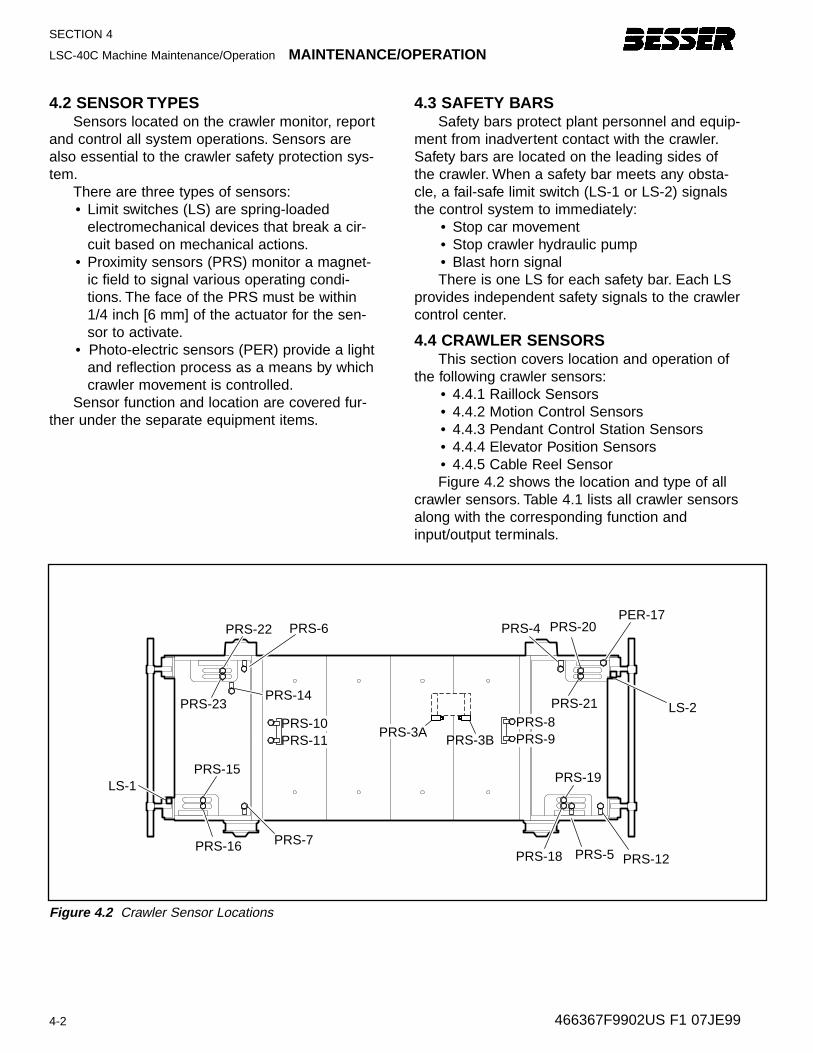
4-2
SECTION 4
LSC-40C Machine Maintenance/Operation MAINTENANCE/OPERATION
4.2 SENSOR TYPESSensors located on the crawler monitor, report
and control all system operations. Sensors arealso essential to the crawler safety protection sys-tem.
There are three types of sensors:• Limit switches (LS) are spring-loaded
electromechanical devices that break a cir-cuit based on mechanical actions.
• Proximity sensors (PRS) monitor a magnet-ic field to signal various operating condi-tions. The face of the PRS must be within1/4 inch [6 mm] of the actuator for the sen-sor to activate.
• Photo-electric sensors (PER) provide a lightand reflection process as a means by whichcrawler movement is controlled.
Sensor function and location are covered fur-ther under the separate equipment items.
4.3 SAFETY BARSSafety bars protect plant personnel and equip-
ment from inadvertent contact with the crawler.Safety bars are located on the leading sides ofthe crawler. When a safety bar meets any obsta-cle, a fail-safe limit switch (LS-1 or LS-2) signalsthe control system to immediately:
• Stop car movement• Stop crawler hydraulic pump• Blast horn signalThere is one LS for each safety bar. Each LS
provides independent safety signals to the crawlercontrol center.
4.4 CRAWLER SENSORSThis section covers location and operation of
the following crawler sensors:• 4.4.1 Raillock Sensors• 4.4.2 Motion Control Sensors• 4.4.3 Pendant Control Station Sensors• 4.4.4 Elevator Position Sensors• 4.4.5 Cable Reel SensorFigure 4.2 shows the location and type of all
crawler sensors. Table 4.1 lists all crawler sensorsalong with the corresponding function andinput/output terminals.
PRS-20PRS-4
PRS-21
PRS-12
PRS-19
PRS-5PRS-18PRS-16
PRS-15 LS-1
PRS-6PRS-22
PRS-23
PRS-7
PER-17
LS-2PRS-10PRS-11
PRS-14
PRS-3APRS-3B
PRS-8PRS-9
Figure 4.2 Crawler Sensor Locations
466367F9902US F1 07JE99
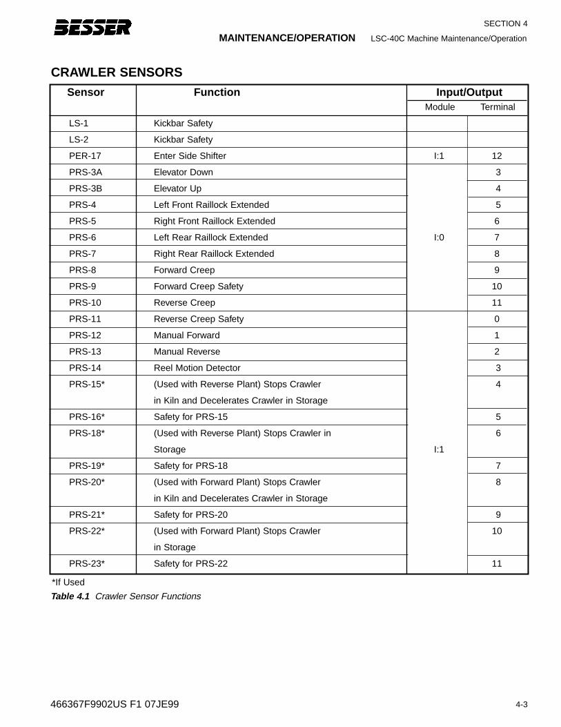
4-3
SECTION 4
466367F9902US F1 07JE99
CRAWLER SENSORS
*If Used
Sensor Function Input/OutputModule Terminal
LS-1 Kickbar Safety
LS-2 Kickbar Safety
PER-17 Enter Side Shifter I:1 12
PRS-3A Elevator Down 3
PRS-3B Elevator Up 4
PRS-4 Left Front Raillock Extended 5
PRS-5 Right Front Raillock Extended 6
PRS-6 Left Rear Raillock Extended I:0 7
PRS-7 Right Rear Raillock Extended 8
PRS-8 Forward Creep 9
PRS-9 Forward Creep Safety 10
PRS-10 Reverse Creep 11
PRS-11 Reverse Creep Safety 0
PRS-12 Manual Forward 1
PRS-13 Manual Reverse 2
PRS-14 Reel Motion Detector 3
PRS-15* (Used with Reverse Plant) Stops Crawler 4
in Kiln and Decelerates Crawler in Storage
PRS-16* Safety for PRS-15 5
PRS-18* (Used with Reverse Plant) Stops Crawler in 6
Storage I:1
PRS-19* Safety for PRS-18 7
PRS-20* (Used with Forward Plant) Stops Crawler 8
in Kiln and Decelerates Crawler in Storage
PRS-21* Safety for PRS-20 9
PRS-22* (Used with Forward Plant) Stops Crawler 10
in Storage
PRS-23* Safety for PRS-22 11
Table 4.1 Crawler Sensor Functions
MAINTENANCE/OPERATION LSC-40C Machine Maintenance/Operation
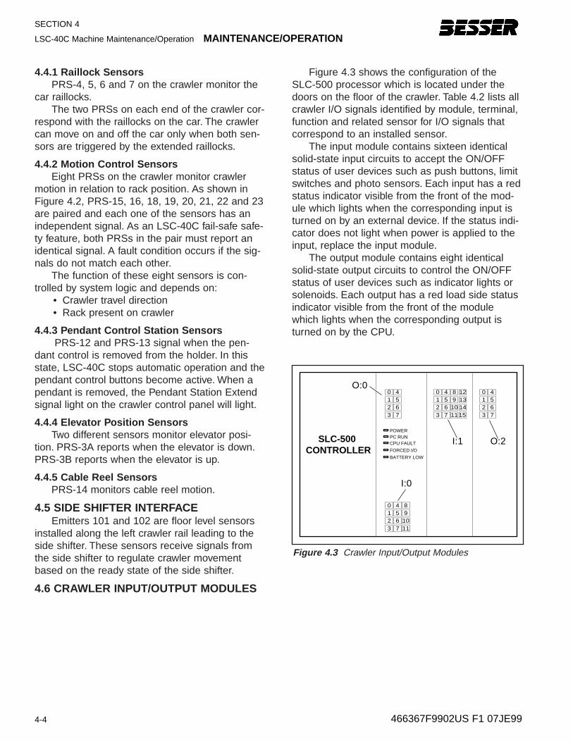
SECTION 4
LSC-40C Machine Maintenance/Operation MAINTENANCE/OPERATION
4-4 466367F9902US F1 07JE99
SLC-500 CONTROLLER
0 4 8 121 5 9 132 6 10 143 7 11
0 4 81 5 92 6 103 7 11
15
0 41 52 63 7
0 41 52 63 7
POWERPC RUNCPU FAULT
FORCED I/O
BATTERY LOW
O:0
I:0
I:1 O:2
Figure 4.3 Crawler Input/Output Modules
4.4.1 Railloc k Sensor s PRS-4, 5, 6 and 7 on the crawler monitor the
car raillocks.The two PRSs on each end of the crawler cor-
respond with the raillocks on the car. The crawlercan move on and off the car only when both sen-sors are triggered by the extended raillocks.
4.4.2 Motion Contr ol Sensor sEight PRSs on the crawler monitor crawler
motion in relation to rack position. As shown inFigure 4.2, PRS-15, 16, 18, 19, 20, 21, 22 and 23are paired and each one of the sensors has anindependent signal. As an LSC-40C fail-safe safe-ty feature, both PRSs in the pair must report anidentical signal. A fault condition occurs if the sig-nals do not match each other.
The function of these eight sensors is con-trolled by system logic and depends on:
• Crawler travel direction • Rack present on crawler
4.4.3 Pendant Contr ol Station Sensor sPRS-12 and PRS-13 signal when the pen-
dant control is removed from the holder. In thisstate, LSC-40C stops automatic operation and thependant control buttons become active. When apendant is removed, the Pendant Station Extendsignal light on the crawler control panel will light.
4.4.4 Elevator Position Sensor sTwo different sensors monitor elevator posi-
tion. PRS-3A reports when the elevator is down.PRS-3B reports when the elevator is up.
4.4.5 Cable Reel Sensor sPRS-14 monitors cable reel motion.
4.5 SIDE SHIFTER INTERFACEEmitters 101 and 102 are floor level sensors
installed along the left crawler rail leading to theside shifter. These sensors receive signals fromthe side shifter to regulate crawler movementbased on the ready state of the side shifter.
4.6 CRAWLER INPUT/OUTPUT MODULES
Figure 4.3 shows the configuration of theSLC-500 processor which is located under thedoors on the floor of the crawler. Table 4.2 lists allcrawler I/O signals identified by module, terminal,function and related sensor for I/O signals thatcorrespond to an installed sensor.
The input module contains sixteen identicalsolid-state input circuits to accept the ON/OFFstatus of user devices such as push buttons, limitswitches and photo sensors. Each input has a redstatus indicator visible from the front of the mod-ule which lights when the corresponding input isturned on by an external device. If the status indi-cator does not light when power is applied to theinput, replace the input module.
The output module contains eight identicalsolid-state output circuits to control the ON/OFFstatus of user devices such as indicator lights orsolenoids. Each output has a red load side statusindicator visible from the front of the modulewhich lights when the corresponding output isturned on by the CPU.
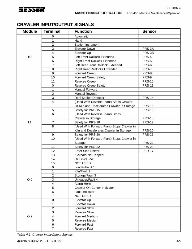
MAINTENANCE/OPERATION LSC-40C Machine Maintenance/Operation
4-5
SECTION 4
466367F9902US F1 07JE99
CRAWLER INPUT/OUTPUT SIGNALS
Module Terminal Function Sensor0 Automatic1 Hand2 Station Increment3 Elevator Down PRS-3A4 Elevator Up PRS-3B
I:0 5 Left Front Raillock Extended PRS-4 6 Right Front Raillock Extended PRS-5 7 Left Rear Front Raillock Extended PRS-6 8 Right Rear Raillocks Extended PRS-7 9 Forward Creep PRS-8
10 Forward Creep Safety PRS-911 Reverse Creep PRS-100 Reverse Creep Safety PRS-111 Manual Forward2 Manual Reverse3 Reel Motion Detector PRS-144 (Used With Reverse Plant) Stops Crawler
in Kiln and Decelerates Crawler in Storage PRS-155 Safety for PRS-15 PRS-166 (Used With Reverse Plant) Stops
Crawler in Storage PRS-18I:1 7 Safety for PRS-18 PRS-19
8 (Used With Forward Plant) Stops Crawler in Kiln and Decelerates Crawler in Storage PRS-20
9 Safety for PRS-20 PRS-2110 (Used With Forward Plant) Stops Crawler in
Storage PRS-2211 Safety for PRS-22 PRS-2312 Enter Side Shifter PER-1713 Kickbars Not Tripped14 Oil Level Low15 NOT USED0 Loader/Fault 11 Kiln/Fault 22 Storage/Fault 3
O:0 3 Unloader/Fault 44 Alarm Horn5 Crawler On Center Indicator6 Fault Indicator7 NOT USED0 Elevator Up1 Elevator Down2 Forward Slow3 Reverse Slow
O:2 4 Forward Medium5 Reverse Medium6 Forward Fast7 Reverse Fast
Table 4.2 Crawler Input/Output Signals

SECTION 4
LSC-40C Machine Operation/Maintenance OPERATION/MAINTENANCE
4-6 466367F9902US F1 07JE99
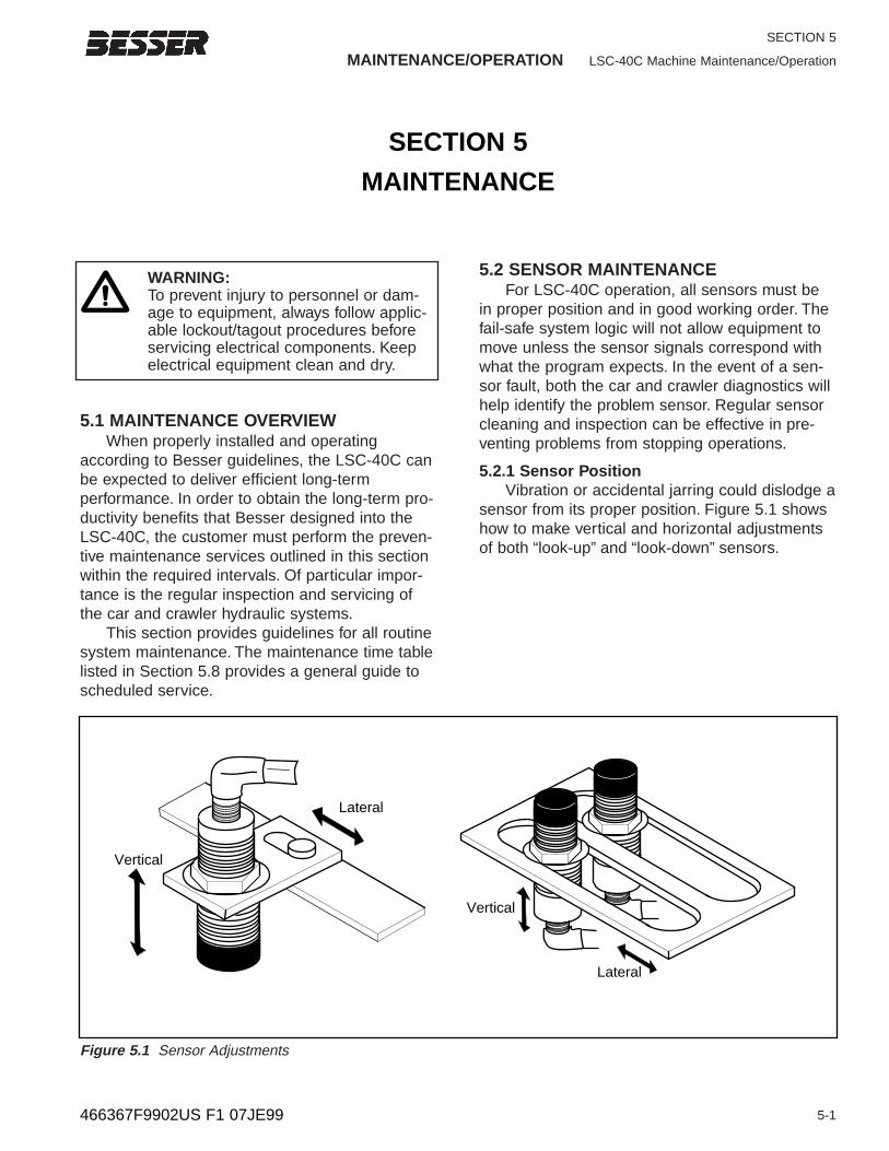
MAINTENANCE/OPERATION LSC-40C Machine Maintenance/Operation
5-1
SECTION 5
5.1 MAINTENANCE OVERVIEWWhen properly installed and operating
according to Besser guidelines, the LSC-40C canbe expected to deliver efficient long-term performance. In order to obtain the long-term pro-ductivity benefits that Besser designed into theLSC-40C, the customer must perform the preven-tive maintenance services outlined in this sectionwithin the required intervals. Of particular impor-tance is the regular inspection and servicing ofthe car and crawler hydraulic systems.
This section provides guidelines for all routinesystem maintenance. The maintenance time tablelisted in Section 5.8 provides a general guide toscheduled service.
5.2 SENSOR MAINTENANCEFor LSC-40C operation, all sensors must be
in proper position and in good working order. Thefail-safe system logic will not allow equipment tomove unless the sensor signals correspond withwhat the program expects. In the event of a sen-sor fault, both the car and crawler diagnostics willhelp identify the problem sensor. Regular sensorcleaning and inspection can be effective in pre-venting problems from stopping operations.
5.2.1 Sensor PositionVibration or accidental jarring could dislodge a
sensor from its proper position. Figure 5.1 showshow to make vertical and horizontal adjustmentsof both “look-up” and “look-down” sensors.
466367F9902US F1 07JE99
SECTION 5
MAINTENANCE
Vertical
Lateral
Figure 5.1 Sensor Adjustments
WARNING:To prevent injury to personnel or dam-age to equipment, always follow applic-able lockout/tagout procedures beforeservicing electrical components. Keepelectrical equipment clean and dry.
Vertical
Lateral
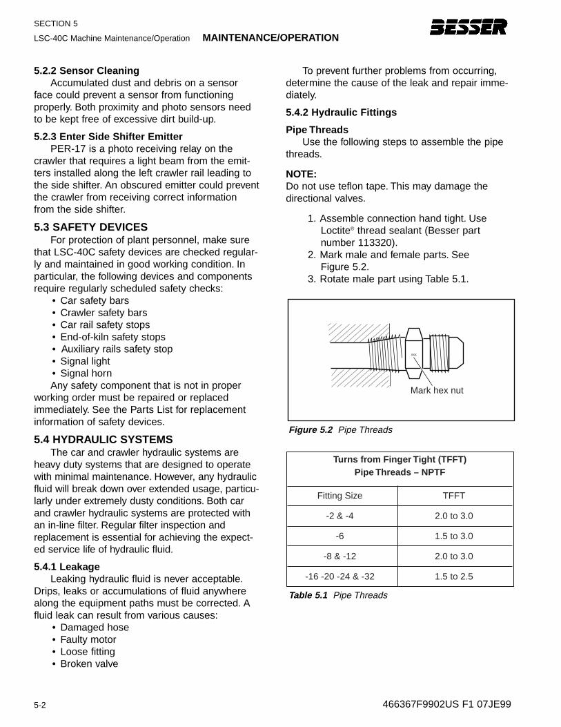
SECTION 5
LSC-40C Machine Maintenance/Operation MAINTENANCE/OPERATION
5-2
5.2.2 Sensor CleaningAccumulated dust and debris on a sensor
face could prevent a sensor from functioningproperly. Both proximity and photo sensors needto be kept free of excessive dirt build-up.
5.2.3 Enter Side Shifter EmitterPER-17 is a photo receiving relay on the
crawler that requires a light beam from the emit-ters installed along the left crawler rail leading tothe side shifter. An obscured emitter could preventthe crawler from receiving correct informationfrom the side shifter.
5.3 SAFETY DEVICESFor protection of plant personnel, make sure
that LSC-40C safety devices are checked regular-ly and maintained in good working condition. Inparticular, the following devices and componentsrequire regularly scheduled safety checks:
• Car safety bars• Crawler safety bars• Car rail safety stops• End-of-kiln safety stops• Auxiliary rails safety stop• Signal light• Signal hornAny safety component that is not in proper
working order must be repaired or replacedimmediately. See the Parts List for replacementinformation of safety devices.
5.4 HYDRAULIC SYSTEMSThe car and crawler hydraulic systems are
heavy duty systems that are designed to operatewith minimal maintenance. However, any hydraulicfluid will break down over extended usage, particu-larly under extremely dusty conditions. Both carand crawler hydraulic systems are protected withan in-line filter. Regular filter inspection andreplacement is essential for achieving the expect-ed service life of hydraulic fluid.
5.4.1 LeakageLeaking hydraulic fluid is never acceptable.
Drips, leaks or accumulations of fluid anywherealong the equipment paths must be corrected. Afluid leak can result from various causes:
• Damaged hose• Faulty motor• Loose fitting• Broken valve
466367F9902US F1 07JE99
xxx
Mark hex nut
Figure 5.2 Pipe Threads
Turns from Finger Tight (TFFT)Pipe Threads – NPTF
Fitting Size
-2 & -4
-6
-8 & -12
-16 -20 -24 & -32
TFFT
2.0 to 3.0
1.5 to 3.0
2.0 to 3.0
1.5 to 2.5
Table 5.1 Pipe Threads
To prevent further problems from occurring,determine the cause of the leak and repair imme-diately.
5.4.2 Hydraulic Fittings
Pipe ThreadsUse the following steps to assemble the pipe
threads.
NOTE:Do not use teflon tape. This may damage thedirectional valves.
1. Assemble connection hand tight. UseLoctite® thread sealant (Besser part number 113320).
2. Mark male and female parts. See Figure 5.2.
3. Rotate male part using Table 5.1.
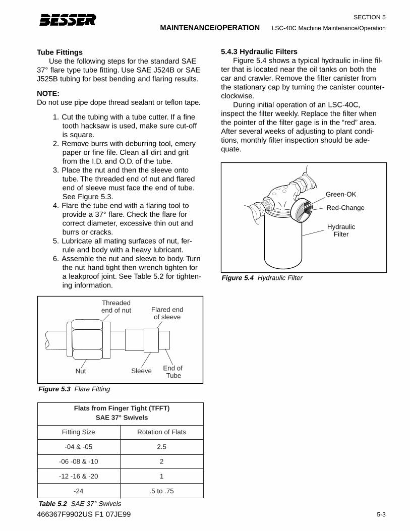
MAINTENANCE/OPERATION LSC-40C Machine Maintenance/Operation
5-3
SECTION 5
Tube FittingsUse the following steps for the standard SAE
37° flare type tube fitting. Use SAE J524B or SAEJ525B tubing for best bending and flaring results.
NOTE:Do not use pipe dope thread sealant or teflon tape.
1. Cut the tubing with a tube cutter. If a finetooth hacksaw is used, make sure cut-offis square.
2. Remove burrs with deburring tool, emerypaper or fine file. Clean all dirt and gritfrom the I.D. and O.D. of the tube.
3. Place the nut and then the sleeve ontotube. The threaded end of nut and flaredend of sleeve must face the end of tube.See Figure 5.3.
4. Flare the tube end with a flaring tool toprovide a 37° flare. Check the flare forcorrect diameter, excessive thin out andburrs or cracks.
5. Lubricate all mating surfaces of nut, fer-rule and body with a heavy lubricant.
6. Assemble the nut and sleeve to body. Turnthe nut hand tight then wrench tighten fora leakproof joint. See Table 5.2 for tighten-ing information.
5.4.3 Hydraulic Filter sFigure 5.4 shows a typical hydraulic in-line fil-
ter that is located near the oil tanks on both thecar and crawler. Remove the filter canister fromthe stationary cap by turning the canister counter-clockwise.
During initial operation of an LSC-40C,inspect the filter weekly. Replace the filter whenthe pointer of the filter gage is in the “red” area.After several weeks of adjusting to plant condi-tions, monthly filter inspection should be ade-quate.
466367F9902US F1 07JE99
Green-OK
Red-Change
HydraulicFilter
Figure 5.4 Hydraulic Filter
End of Tube
Sleeve
Threadedend of nut Flared end
of sleeve
Nut
Figure 5.3 Flare Fitting
Flats from Finger Tight (TFFT)SAE 37° Swivels
Fitting Size
-04 & -05
-06 -08 & -10
-12 -16 & -20
-24
Rotation of Flats
2.5
2
1
.5 to .75
Table 5.2 SAE 37° Swivels
5.4.4 Fluid ConditionAside from contamination, hydraulic fluid can
undergo physical and chemical changes thatreduce its effectiveness. Resulting problems fromusing decomposed fluid include:
• Accelerated pump wear • Reduced motor power • Slower equipment movementBesser Company offers an inspection kit
(Besser Part No. 114546) to analyze hydraulicfluid condition. The kit analyzes the last four fluidsamples providing a data comparison of:
• Particle counts• Water content • Viscosity• Wear metal and additive contentA diagnostic statement provides a layman
explanation of the test and its results regardingthe condition of the equipment and the hydraulicfluid. The information is graphed against ISO(International Standards Organization) standardsto show the overall cleanliness of the system.
5-4 466367F9902US F1 07JE99
SECTION 5LSC-40C Machine Maintenance/Operation MAINTENANCE/OPERATION
5.5 RAILSLSC-40C equipment is sufficiently heavy that
normal levels of concrete dust should not hindermovement. As often as required by plant condi-tions, clean out the grooves along the car andcrawler rails to prevent a build-up of debris. Also,make sure that the top surfaces of the actuatorsare kept clean.
5.6 CABLE REELThis section covers two cable reel service pro-
cedures:• Cable Replacement• Spring ReplacementThe cable is subjected to surface wear and
fatigue from continual unwinding and winding. Thereare three internal cable reel springs. A loose or flop-py cable that rewinds with reduced spring tensionindicates the need for spring replacement.
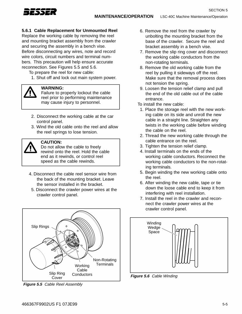
6. Remove the reel from the crawler byunbolting the mounting bracket from thebase of the crawler. Secure the reel andbracket assembly in a bench vise.
7. Remove the slip ring cover and disconnectthe working cable conductors from thenon-rotating terminals.
8. Remove the old working cable from thereel by pulling it sideways off the reel.Make sure that the removal process doesnot tension the spring.
9. Loosen the tension relief clamp and pullthe end of the old cable out of the cableentrance.
To install the new cable:1. Place the storage reel with the new work-
ing cable on its side and unroll the newcable in a straight line. Straighten anytwists in the working cable before windingthe cable on the reel.
2. Thread the new working cable through thecable entrance on the reel.
3. Tighten the tension relief clamp.4. Install terminals on the ends of the
working cable conductors. Reconnect theworking cable conductors to the non-rotat-ing terminals.
5. Begin winding the new working cable ontothe reel.
6. After winding the new cable, tape or tiedown the loose cable end to keep it frominterfering with reel installation.
7. Install the reel in the crawler and recon-nect the crawler power wires at thecrawler control panel.
MAINTENANCE/OPERATION LSC-40C Machine Maintenance/Operation
5-5
SECTION 5
5.6.1 Cable Replacement f or Unmounted ReelReplace the working cable by removing the reeland mounting bracket assembly from the crawlerand securing the assembly in a bench vise.Before disconnecting any wires, note and recordwire colors, circuit numbers and terminal num-bers. This precaution will help ensure accuratereconnection. See Figures 5.5 and 5.6.
To prepare the reel for new cable:1. Shut off and lock out main system power.
2. Disconnect the working cable at the carcontrol panel.
3. Wind the old cable onto the reel and allowthe reel springs to lose tension.
4. Disconnect the cable reel sensor wire fromthe back of the mounting bracket. Leavethe sensor installed in the bracket.
5. Disconnect the crawler power wires at thecrawler control panel.
466367F9902US F1 07JE99
WindingWedgeSpace
Figure 5.6 Cable WindingSlip Ring
Cover
Slip Rings
WorkingCable
Conductors
Non-RotatingTerminals
Figure 5.5 Cable Reel Assembly
WARNING:Failure to properly lockout the cablereel prior to performing maintenancemay cause injury to personnel.
CAUTION:Do not allow the cable to freelyrewind onto the reel. Hold the cableend as it rewinds, or control reelspeed as the cable rewinds.
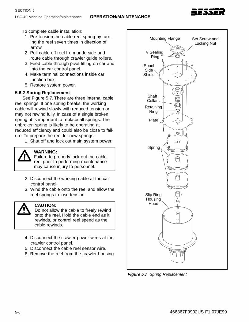
SECTION 5
LSC-40 Machine Operation/Maintenance OPERATION/MAINTENANCE
5-6
To complete cable installation:1. Pre-tension the cable reel spring by turn-
ing the reel seven times in direction ofarrow.
2. Pull cable off reel from underside androute cable through crawler guide rollers.
3. Feed cable through pivot fitting on car andinto the car control panel.
4. Make terminal connections inside carjunction box.
5. Restore system power.
5.6.2 Spring ReplacementSee Figure 5.7. There are three internal cable
reel springs. If one spring breaks, the workingcable will rewind slowly with reduced tension ormay not rewind fully. In case of a single brokenspring, it is important to replace all springs. Theunbroken spring is likely to be operating atreduced efficiency and could also be close to fail-ure. To prepare the reel for new springs:
1. Shut off and lock out main system power.
2. Disconnect the working cable at the carcontrol panel.
3. Wind the cable onto the reel and allow thereel springs to lose tension.
4. Disconnect the crawler power wires at thecrawler control panel.
5. Disconnect the cable reel sensor wire.6. Remove the reel from the crawler housing.
466367F9902US F1 07JE99
WARNING:Failure to properly lock out the cablereel prior to performing maintenancemay cause injury to personnel.
CAUTION:Do not allow the cable to freely rewindonto the reel. Hold the cable end as itrewinds, or control reel speed as thecable rewinds.
Mounting Flange
SpoolSide
Shield
ShaftCollar
RetainingRing
Plate
Spring
V Sealing Ring
Set Screw andLocking Nut
Slip RingHousing
Hood
Figure 5.7 Spring Replacement
OPERATION/MAINTENANCE LSC-40 Machine Operation/Maintenance
5-7
SECTION 5
7. Before starting disassembly, make surethat there is no tension on the springs.The outer mounting flange should turnfreely.
8. Loosen the screws holding the mountingflange and the spool side shield in place.After removing the spool shield, the othercomponents can be pulled off the shaft.The spring removal process can beobserved from Figure 5.7.
9. Unless a new working cable is beingreplaced at the same time, it is not neces-sary to remove the slip ring cover or dis-connect the working cable conductors.
NOTE:When installing new springs, pay close attentionto the assembly sequence of the plate andsprings.
To assemble the cable reel:1. Follow the sequence shown in Figure 5.7.
Press down on the shaft to secure com-ponents snugly.
2. Replace springs or other components asneeded.
To place cable reel back in service:1. Install the reel in the crawler and recon-
nect the crawler power wires and thecable reel sensor wire.
2. Pre-tension the cable reel spring by turn-ing the reel seven times in direction ofarrow.
3. Pull cable off reel from underside androute cable through crawler guide rollers.
4. Feed cable through pivot fitting on car andinto the car control panel.
5. Make terminal connections inside car con-trol panel.
6. Restore system power.
466367F9902US F1 07JE99
WARNING:Exercise extreme care when workingwith cable reel springs. A spring undertension is dangerous and could causeserious injury.
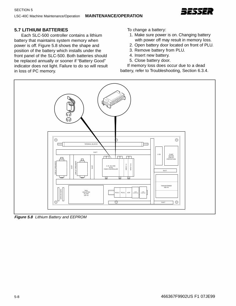
SECTION 5
LSC-40C Machine Maintenance/Operation MAINTENANCE/OPERATION
5-8
5.7 LITHIUM BATTERIESEach SLC-500 controller contains a lithium
battery that maintains system memory whenpower is off. Figure 5.8 shows the shape andposition of the battery which installs under thefront panel of the SLC-500. Both batteries shouldbe replaced annually or sooner if “Battery Good”indicator does not light. Failure to do so will resultin loss of PC memory.
To change a battery:1. Make sure power is on. Changing battery
with power off may result in memory loss.2. Open battery door located on front of PLU.3. Remove battery from PLU.4. Insert new battery.5. Close battery door.
If memory loss does occur due to a dead battery, refer to Troubleshooting, Section 6.3.4.
466367F9902US F1 07JE99
TERMINAL BLOCKS
DUCT
A. B. SLC-50020 I/O
FIXED CONTROLLER
TEALISOLATION
FILTER150 VA
PCS-2 PCS-1 ACR
DUCT
DUCT
1 CB PUMPMOTORCIRCUIT
PROTECTION
TRANSFORMER500 VA
PUMPCONTACTOR
PUMPOVERLOAD
DU
CT
INP
UT
I-1
INP
UT
O-2
DU
CT
CIR
CU
IT B
RE
AK
ER
S
CIR
CU
IT B
RE
AK
ER
S
GR
OU
ND
BA
RS
Figure 5.8 Lithium Battery and EEPROM
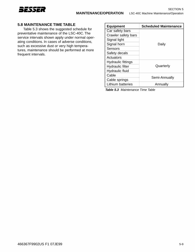
5-9466367F9902US F1 07JE99
MAINTENANCE/OPERATION LSC-40C Machine Maintenance/Operation
SECTION 5
5.8 MAINTENANCE TIME TABLETable 5.3 shows the suggested schedule for
preventative maintenance of the LSC-40C. Theservice intervals shown apply under normal oper-ating conditions. In cases of adverse conditions,such as excessive dust or very high tempera-tures, maintenance should be performed at morefrequent intervals.
Table 5.3 Maintenance Time Table
Equipment Scheduled MaintenanceCar safety barsCrawler safety barsSignal lightSignal horn DailySensorsSafety decalsActuatorsHydraulic fittingsHydraulic filterHydraulic fluidCableCable springsLithium batteries Annually
Quarterly
Semi-Annually

SECTION 5
LSC-40 Machine Operation/Maintenance OPERATION/MAINTENANCE
5-10 466367F9902US F1 07JE99
MAINTENANCE/OPERATION LSC-40C Machine Maintenance/Operation
6-1
SECTION 6
Most troubleshooting is handled by the com-puter messages in the car and crawler diagnos-tics. Here are some common problems:
• 6.1 Car Diagnostics• 6.2 Crawler Diagnostics• 6.3 Other Diagnostic Checks
6.1 CAR DIAGNOSTICSIf an error originates with the car, the Operator
Message Center on the Car Program Screen dis-plays an error message and the required operatoraction. See Section 3.2.8.
6.2 CRAWLER DIAGNOSTICSIf an error originates with the crawler, one or
more lamps on the crawler control panel illumi-nate to identify the error condition. Use theCrawler Fault Diagnostic Charts to determineerror and proper action. See Section 3.2.3.
466367F9902US F1 07JE99
SECTION 6
TROUBLESHOOTING
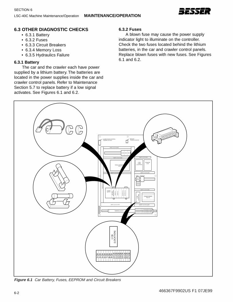
SECTION 6
LSC-40C Machine Maintenance/Operation MAINTENANCE/OPERATION
6-2
6.3 OTHER DIAGNOSTIC CHECKS• 6.3.1 Battery • 6.3.2 Fuses• 6.3.3 Circuit Breakers• 6.3.4 Memory Loss• 6.3.5 Hydraulics Failure
6.3.1 Batter yThe car and the crawler each have power
supplied by a lithium battery. The batteries arelocated in the power supplies inside the car andcrawler control panels. Refer to MaintenanceSection 5.7 to replace battery if a low signal activates. See Figures 6.1 and 6.2.
6.3.2 FusesA blown fuse may cause the power supply
indicator light to illuminate on the controller.Check the two fuses located behind the lithiumbatteries, in the car and crawler control panels.Replace blown fuses with new fuses. See Figures6.1 and 6.2.
OU
TP
UT
0-5
OU
TP
UT
0-4
INP
UT
I-2
- -
INP
UT
I-1
SLC
500
PR
OC
ES
SO
RPOWERSUPPLY
DUCT 2 X 3 X 17.00
TERMINAL BLOCKS
GR
OU
ND
BA
R
DU
CT
1.5
X 3
X 3
1.00
DUCT 1 X 3 X 15.00
DUCT 1 X 3 X 15.50DUCT 1 X 3 X 9.00
1 MPCPUMP
(LOCATION)
ACR1
BEACONTERMINAL BLOCKS
MCR RSCR
DUCT 1 X 3 X 15.50
NOISE SUPPRESSOR300 VA
CRAWLERPUMP
AUXCONTACT
OVERLOAD(LOCATION)
DUCT 1 X 3 X 11.00
DUCT 1 X 3 X 11.00
1 C
B(L
OC
AT
ION
)
TRANSFORMER750 VA
DUCT 1 X 3 X 11.00
2-C
B
CRAWLER4-CB
3-C
B5-
CB
6-C
B7-
CB
8-C
B9-
CB
10-C
B11
-CB
12-C
B13
-CB
14-C
B15
-CB
16-C
B17
-CB
ALARM & RADIO CONTROLTERMINAL BLOCKS
1 C
B(L
OC
AT
ION
)
2-C
B3-
CB
5-C
B6-
CB
7-C
B8-
CB
9-C
B10
-CB
11-C
B12
-CB
13-C
B14
-CB
15-C
B16
-CB
17-C
B
Figure 6.1 Car Battery, Fuses, EEPROM and Circuit Breakers
466367F9902US F1 07JE99
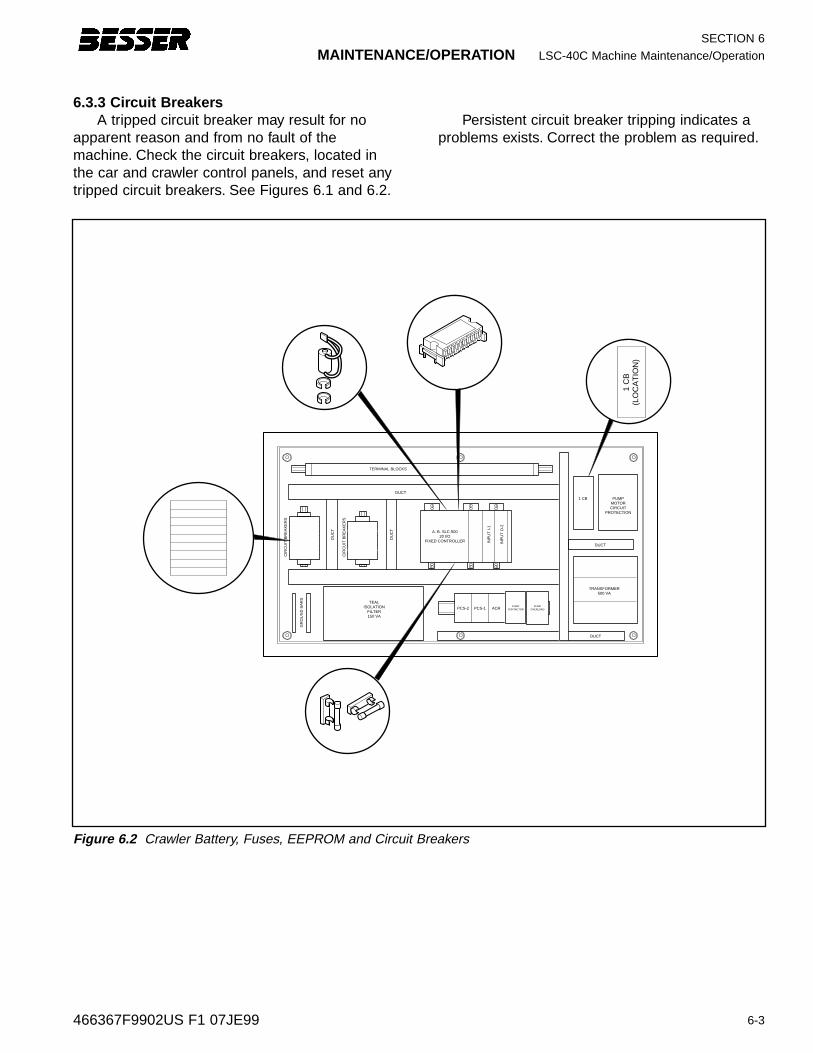
6-3466367F9902US F1 07JE99
MAINTENANCE/OPERATION LSC-40C Machine Maintenance/Operation
SECTION 6
1 C
B(L
OC
AT
ION
)
TERMINAL BLOCKS
DUCT
A. B. SLC-50020 I/O
FIXED CONTROLLER
TEALISOLATION
FILTER150 VA
PCS-2 PCS-1 ACR
DUCT
DUCT
1 CB PUMPMOTORCIRCUIT
PROTECTION
TRANSFORMER500 VA
PUMPCONTACTOR
PUMPOVERLOAD
DU
CT
INP
UT
I-1
INP
UT
O-2
DU
CT
CIR
CU
IT B
RE
AK
ER
S
CIR
CU
IT B
RE
AK
ER
S
GR
OU
ND
BA
RS
Figure 6.2 Crawler Battery, Fuses, EEPROM and Circuit Breakers
6.3.3 Circuit Breaker sA tripped circuit breaker may result for no
apparent reason and from no fault of themachine. Check the circuit breakers, located inthe car and crawler control panels, and reset anytripped circuit breakers. See Figures 6.1 and 6.2.
Persistent circuit breaker tripping indicates aproblems exists. Correct the problem as required.
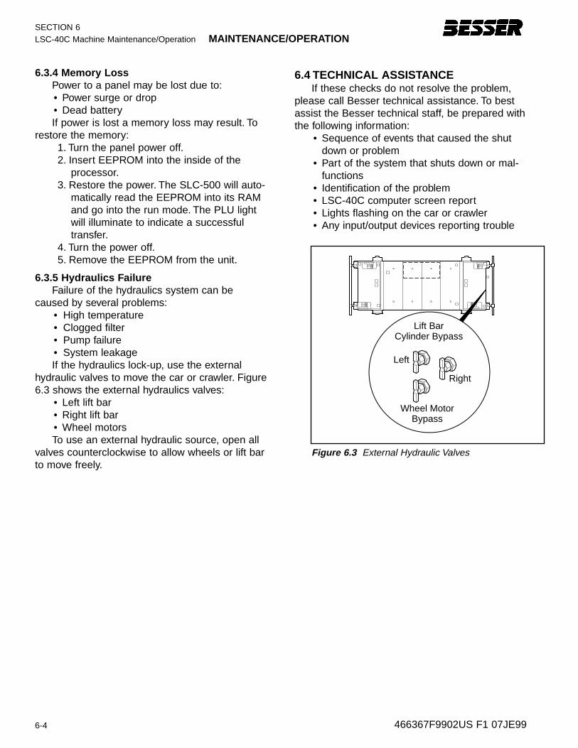
6-4 466367F9902US F1 07JE99
6.4 TECHNICAL ASSISTANCEIf these checks do not resolve the problem,
please call Besser technical assistance. To bestassist the Besser technical staff, be prepared withthe following information:
• Sequence of events that caused the shutdown or problem
• Part of the system that shuts down or mal-functions
• Identification of the problem• LSC-40C computer screen report• Lights flashing on the car or crawler• Any input/output devices reporting trouble
Left
Right
Wheel MotorBypass
Lift BarCylinder Bypass
Figure 6.3 External Hydraulic Valves
SECTION 6LSC-40C Machine Maintenance/Operation MAINTENANCE/OPERATION
6.3.4 Memor y LossPower to a panel may be lost due to:• Power surge or drop• Dead batteryIf power is lost a memory loss may result. To
restore the memory:1. Turn the panel power off.2. Insert EEPROM into the inside of the
processor.3. Restore the power. The SLC-500 will auto-
matically read the EEPROM into its RAMand go into the run mode. The PLU lightwill illuminate to indicate a successfultransfer.
4. Turn the power off.5. Remove the EEPROM from the unit.
6.3.5 Hydraulics F ailureFailure of the hydraulics system can be
caused by several problems:• High temperature• Clogged filter• Pump failure• System leakageIf the hydraulics lock-up, use the external
hydraulic valves to move the car or crawler. Figure6.3 shows the external hydraulics valves:
• Left lift bar• Right lift bar• Wheel motorsTo use an external hydraulic source, open all
valves counterclockwise to allow wheels or lift barto move freely.


