LST42H PRINTED IN U.S.A. FORM NO. 3-141 (10/12/21) 42" SNOW THROWER the fastest way to purchase parts www.speedepart.com youtube.com/c/agrifab Video Instruction Guide Want more information or assembly tips?
Transcript
LST42H
PRINTED IN U.S.A. FORM NO. 3-141 (10/12/21)
42" SNOW THROWER
the fastest way to purchase parts www.speedepart.com
youtube .com/c /a g r i fa b
VideoInstructionGuide
Want more information or assembly tips?
2
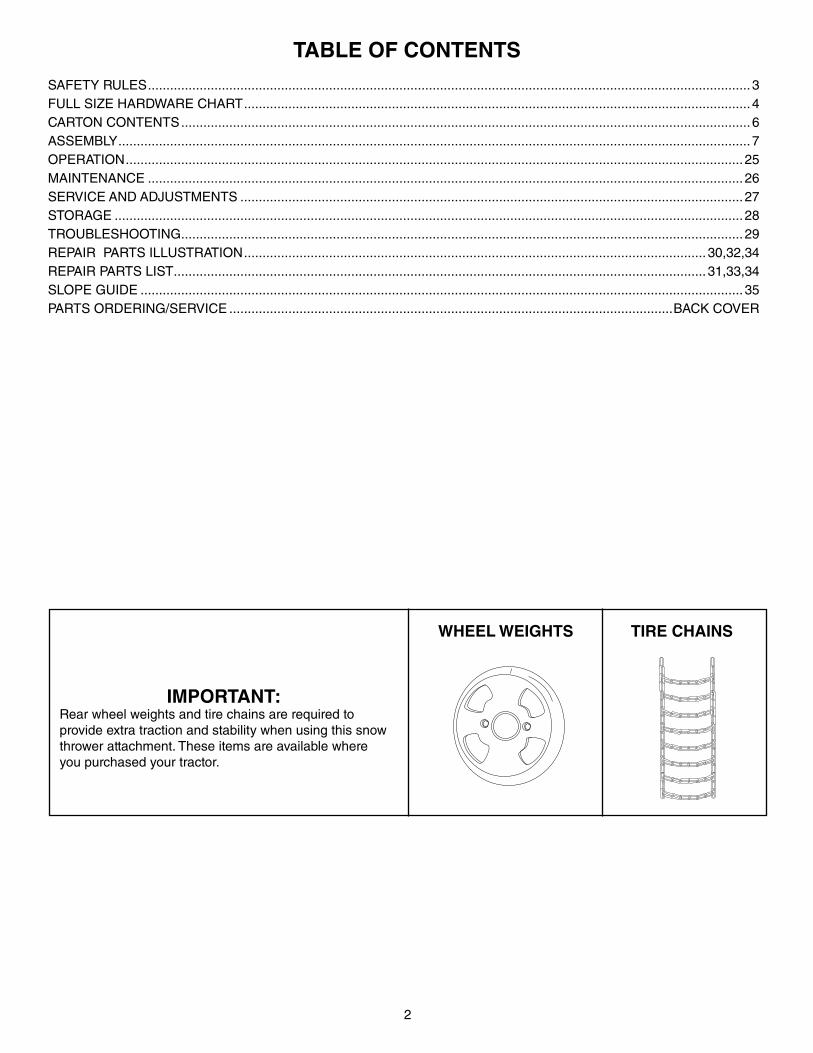
TABLE OF CONTENTS
SAFETY RULES ...................................................................................................................................................................3FULL SIZE HARDWARE CHART .........................................................................................................................................4CARTON CONTENTS ..........................................................................................................................................................6ASSEMBLY ...........................................................................................................................................................................7OPERATION .......................................................................................................................................................................25MAINTENANCE .................................................................................................................................................................26SERVICE AND ADJUSTMENTS ........................................................................................................................................27STORAGE ..........................................................................................................................................................................28TROUBLESHOOTING ........................................................................................................................................................29REPAIR PARTS ILLUSTRATION .............................................................................................................................30,32,34REPAIR PARTS LIST ................................................................................................................................................31,33,34SLOPE GUIDE ...................................................................................................................................................................35 PARTS ORDERING/SERVICE ........................................................................................................................BACK COVER
IMPORTANT:Rear wheel weights and tire chains are required to provide extra traction and stability when using this snow thrower attachment. These items are available where you purchased your tractor.
WHEEL WEIGHTS TIRE CHAINS
3
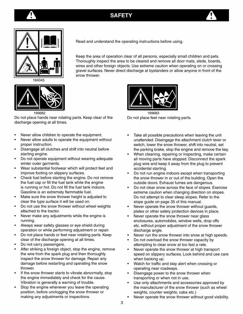
SAFETY
Read and understand the operating instructions before using.
Keep the area of operation clear of all persons, especially small children and pets.Thoroughly inspect the area to be cleared and remove all door mats, sleds, boards, wires and other foreign objects. Use extreme caution when operating on or crossing gravel surfaces. Never direct discharge at bystanders or allow anyone in front of the snow thrower.
Do not place hands near rotating parts. Keep clear of the discharge opening at all times.
Do not place feet near rotating parts.
• Never allow children to operate the equipment.• Never allow adults to operate the equipment without
proper instruction.• Disengage all clutches and shift into neutral before
starting engine.• Do not operate equipment without wearing adequate
winter outer garments.• Wear substantial footwear which will protect feet and
improve footing on slippery surfaces.• Check fuel before starting the engine. Do not remove
the fuel cap or fill the fuel tank while the engine is running or hot. Do not fill the fuel tank indoors. Gasoline is an extremely flammable fuel.
• Make sure the snow thrower height is adjusted to clear the type surface it will be used on.
• Do not use the snow thrower without wheel weights attached to the tractor.
• Never make any adjustments while the engine is running.
• Always wear safety glasses or eye shield during operation or while performing adjustment or repair.
• Do not place hands or feet near rotating parts. Keep clear of the discharge opening at all times.
• Do not carry passengers.• After striking a foreign object, stop the engine, remove
the wire from the spark plug and then thoroughly inspect the snow thrower for damage. Repair any damage before restarting and operating the snow thrower.
• If the snow thrower starts to vibrate abnormally, stop the engine immediately and check for the cause. Vibration is generally a warning of trouble.
• Stop the engine whenever you leave the operating position, before unclogging the snow thrower or making any adjustments or inspections.
• Take all possible precautions when leaving the unit unattended. Disengage the attachment clutch lever or switch, lower the snow thrower, shift into neutral, set the parking brake, stop the engine and remove the key.
• When cleaning, repairing or inspecting, make certain all moving parts have stopped. Disconnect the spark plug wire and keep it away from the plug to prevent accidental starting.
• Do not run engine indoors except when transporting the snow thrower in or out of the building. Open the outside doors. Exhaust fumes are dangerous.
• Do not clear snow across the face of slopes. Exercise extreme caution when changing direction on slopes. Do not attempt to clear steep slopes. Refer to the slope guide on page 35 of this manual.
• Never operate the snow thrower without guards, plates or other safety protection devices in place.
• Never operate the snow thrower near glass enclosures, automobiles, window wells, drop offs etc. without proper adjustment of the snow thrower discharge angle.
• Never run the snow thrower into snow at high speeds.• Do not overload the snow thrower capacity by
attempting to clear snow at too fast a rate.• Never operate the snow thrower at high transport
speed on slippery surfaces. Look behind and use care when backing up.
• Watch for traffic and stay alert when crossing or operating near roadways.
• Disengage power to the snow thrower when transporting or when not in use.
• Use only attachments and accessories approved by the manufacturer of the snow thrower (such as wheel weights, counter weights, cabs etc.)
• Never operate the snow thrower without good visibility.
184045
199683199682
4
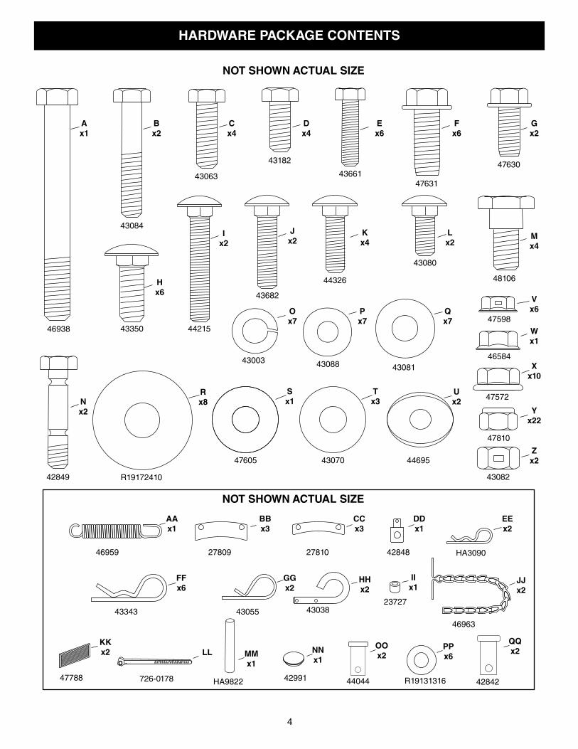
HARDWARE PACKAGE CONTENTS
Jx2
Hx6
Lx2
Px7
Xx10
Vx6
Yx22
Wx1
Rx8
Sx1
Ux2
Zx2
Ox7
NOT SHOWN ACTUAL SIZE
NOT SHOWN ACTUAL SIZE
Nx2
Qx7
Ax1
46938
43084
43182
4366147631
43350 44215
43682
44326
43080
42849
43003 43088 43081
R19172410
47605 44695
43082
47810
47572
46584
47598
43063
AAx1
GGx2
EEx2
DDx1
CCx3
BBx3
FFx6
LL
HHx2
IIx1
JJx2
KKx2
46959 27809 27810 42848 HA3090
43343 43055 43038
46963
726-017847788 HA9822 42991 44044 42842R19131316
23727
MMx1
NNx1
QQx2
OOx2
PPx6
Bx2
Cx4
Dx4
Ex6
Fx6
Mx4
47630
48106
Gx2
Ix2
Kx4
Tx3
43070
5
REF. QTY. DESCRIPTION
A 1 Hex Bolt, 3/8" x 3-1/4"
B 2 Hex Bolt, 5/16" x 1-3/4"
C 4 Hex Bolt, 5/16" x 1"
D 4 Hex Bolt, 5/16" x 3/4"
E 6 Hex Bolt, 1/4" x 1"
F 6 Hex Bolt, 3/8" x 1" (Thread Forming)
G 2 Hex Bolt, 5/16" x 3/4" (Thread Forming)
H 6 Carriage Bolt, 3/8" x 1"
I 2 Carriage Bolt, 5/16" x 1-3/4"
J 2 Carriage Bolt , 5/16" x 1-1/4"
K 4 Carriage Bolt, 5/16" x 1"
L 2 Carriage Bolt, 5/16" x 3/4"
M 4 Shoulder Bolt
N 2 Shear Bolt (spare parts)
O 7 Lock Washer, 3/8"
P 7 Washer, 1/4"
Q 22 Washer, 5/16" (Extra washers included)
R 8 Washer, 1/2"
S 1 Washer, 3/8" (Thin)
T 3 Washer, 3/8"
U 2 Bowed Washer
V 6 Flanged Nut, 1/4"
REF. QTY. DESCRIPTION
W 1 Flanged Nut, 5/16"
X 10 Flanged Nut, 3/8"
Y 22 Nylock Nut, 5/16" (2 spare parts)
Z 2 Hex Lock Nut, 3/8"
AA 1 Spring
BB 3 Chute Keeper
CC 3 Chute Spacer
DD 1 Trunnion
EE 2 Hairpin Cotter, 5/64"
FF 6 Hairpin Cotter, 1/8"
GG 2 Hairpin Cotter, 3/32"
HH 2 Lock Pin
II 1 Small Spacer
JJ 2 Chain, Tensioning
KK 2 Tail Reflector
LL 2 Nylon Tie
MM 1 Grip
NN 1 Plug
OO 2 Clevis Pin, 3/8" x 3/4"
PP 6 Washer
QQ 2 Clevis Pin, 1/2" x 7/8"
6
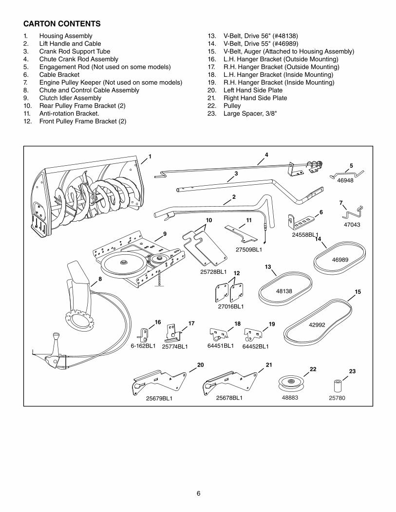
CARTON CONTENTS
1. Housing Assembly2. Lift Handle and Cable3. Crank Rod Support Tube4. Chute Crank Rod Assembly5. Engagement Rod (Not used on some models)6. Cable Bracket7. Engine Pulley Keeper (Not used on some models)8. Chute and Control Cable Assembly9. Clutch Idler Assembly10. Rear Pulley Frame Bracket (2)11. Anti-rotation Bracket.12. Front Pulley Frame Bracket (2)
13. V-Belt, Drive 56" (#48138) 14. V-Belt, Drive 55" (#46989)15. V-Belt, Auger (Attached to Housing Assembly)16. L.H. Hanger Bracket (Outside Mounting)17. R.H. Hanger Bracket (Outside Mounting)18. L.H. Hanger Bracket (Inside Mounting)19. R.H. Hanger Bracket (Inside Mounting)20. Left Hand Side Plate21. Right Hand Side Plate22. Pulley23. Large Spacer, 3/8"
46989
48138
42992
11
5
7
17
2
4
6
191816
8
15
13
1
9
3
20 21
14
25678BL125679BL1
27509BL1
64452BL164451BL125774BL16-162BL1
47043
46948
25728BL1
24558BL1
10
12
27016BL1
48883 25780
22 23
7
• Remove all parts and hardware packages from the carton. Lay out parts and hardware and identify using the illustrations on pages 4 and 6.
NOTE: Not all of the supplied parts and hardware will be needed for your particular tractor. Unneeded items may be discarded after you have completed assembly and checked operation of unit. DO NOT DISCARD the two spare shear bolts and 5/16" nylock nuts. Refer to the Service and Adjustments section on page 27.
Before performing these instructions, refer to the Service and Adjustments section of your tractor owner's manual for specific safety instructions.
• Allow engine, muffler and exhaust deflector to cool before beginning.
• Remove any front or rear attachment which is mounted to your tractor.
• Remove the mower deck. Refer to your tractor owner's manual for removal instructions. Mark all loose parts and save for reassembly.
• Remove the tractor hood. Refer to your tractor owner's manual for removal instructions.
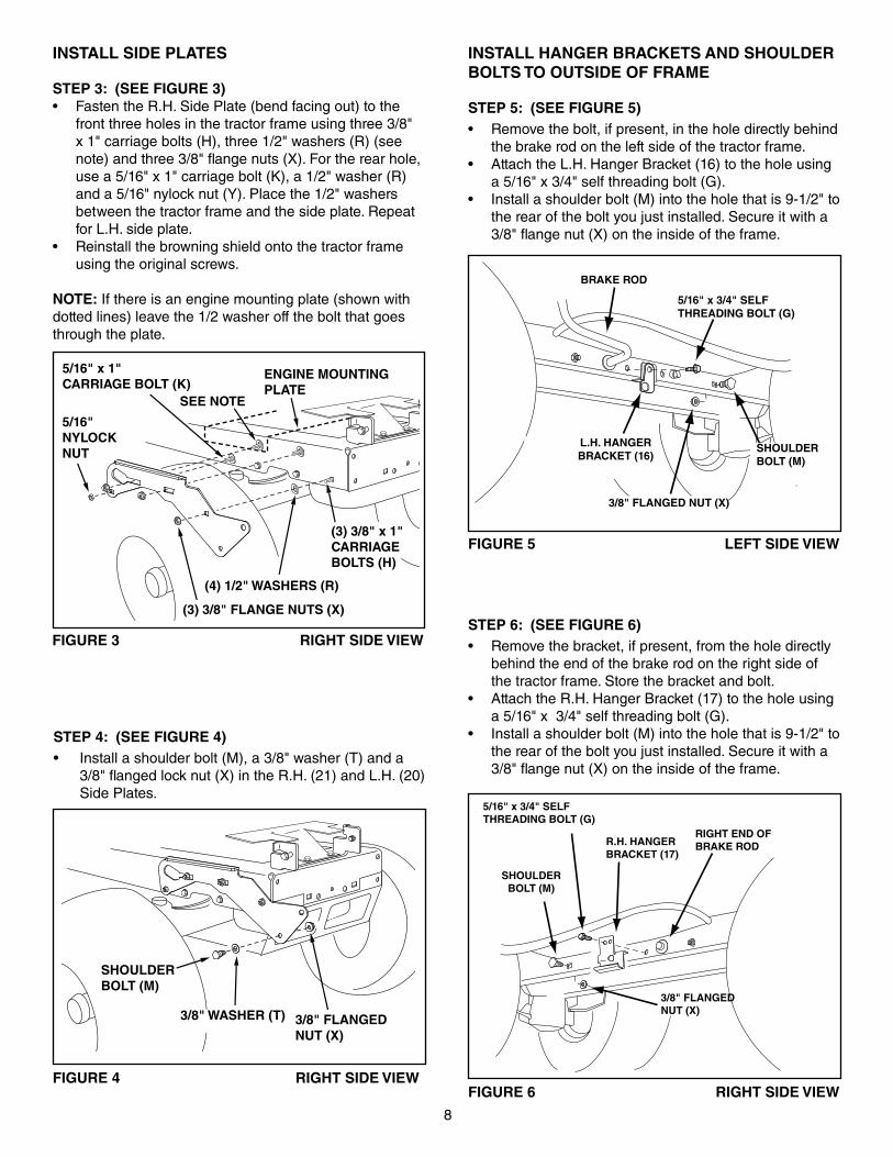
FIGURE 2 RIGHT SIDE VIEW
IMPORTANT: Right hand (R.H.) and left hand (L.H.) side of the tractor are determined from the operators position while seated on the tractor.
REMOVE BROWNING SHIELD
REMOVE FRONT SCREWS
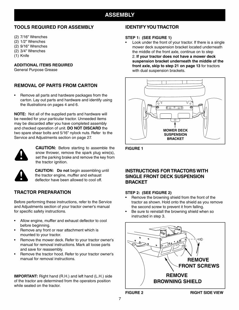
MOWER DECK SUSPENSION
BRACKET
FIGURE 1
INSTRUCTIONS FOR TRACTORS WITH SINGLE FRONT DECK SUSPENSION BRACKET
STEP 2: (SEE FIGURE 2)• Remove the browning shield from the front of the
tractor as shown. Hold onto the shield as you remove the second screw to prevent it from falling.
• Be sure to reinstall the browning shield when so instructed in step 3.
IDENTIFY YOU TRACTOR
STEP 1: (SEE FIGURE 1)• Look under the front of your tractor. If there is a single
mower deck suspension bracket located underneath the middle of the front axle, continue on to step 2. If your tractor does not have a mower deck suspension bracket underneath the middle of the front axle, skip to step 21 on page 13 for tractors with dual suspension brackets.
ASSEMBLY
CAUTION: Before starting to assemble the snow thrower, remove the spark plug wire(s), set the parking brake and remove the key from the tractor ignition.
CAUTION: Do not begin assembling until the tractor engine, muffler and exhaust deflector have been allowed to cool off.
8
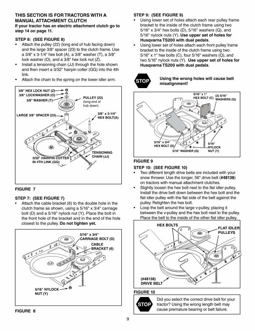
STEP 4: (SEE FIGURE 4)• Install a shoulder bolt (M), a 3/8" washer (T) and a
3/8" flanged lock nut (X) in the R.H. (21) and L.H. (20) Side Plates.
FIGURE 4 RIGHT SIDE VIEW
FIGURE 3 RIGHT SIDE VIEW
5/16"NYLOCKNUT
5/16" x 1"CARRIAGE BOLT (K)
ENGINE MOUNTING PLATE
(4) 1/2" WASHERS (R)
(3) 3/8" FLANGE NUTS (X)
(3) 3/8" x 1"CARRIAGEBOLTS (H)
SEE NOTE
INSTALL SIDE PLATES
STEP 3: (SEE FIGURE 3)• Fasten the R.H. Side Plate (bend facing out) to the
front three holes in the tractor frame using three 3/8" x 1" carriage bolts (H), three 1/2" washers (R) (see note) and three 3/8" flange nuts (X). For the rear hole, use a 5/16" x 1" carriage bolt (K), a 1/2" washer (R) and a 5/16" nylock nut (Y). Place the 1/2" washers between the tractor frame and the side plate. Repeat for L.H. side plate.
• Reinstall the browning shield onto the tractor frame using the original screws.
NOTE: If there is an engine mounting plate (shown with dotted lines) leave the 1/2 washer off the bolt that goes through the plate.
INSTALL HANGER BRACKETS AND SHOULDER BOLTS TO OUTSIDE OF FRAME
STEP 5: (SEE FIGURE 5)• Remove the bolt, if present, in the hole directly behind
the brake rod on the left side of the tractor frame.• Attach the L.H. Hanger Bracket (16) to the hole using
a 5/16" x 3/4" self threading bolt (G).• Install a shoulder bolt (M) into the hole that is 9-1/2" to
the rear of the bolt you just installed. Secure it with a 3/8" flange nut (X) on the inside of the frame.
FIGURE 5 LEFT SIDE VIEW
5/16" x 3/4" SELFTHREADING BOLT (G)
L.H. HANGERBRACKET (16)
BRAKE ROD
3/8" FLANGED NUT (X)
SHOULDERBOLT (M)
5/16" x 3/4" SELFTHREADING BOLT (G)
R.H. HANGERBRACKET (17)
RIGHT END OFBRAKE ROD
3/8" FLANGEDNUT (X)
SHOULDERBOLT (M)
STEP 6: (SEE FIGURE 6)• Remove the bracket, if present, from the hole directly
behind the end of the brake rod on the right side of the tractor frame. Store the bracket and bolt.
• Attach the R.H. Hanger Bracket (17) to the hole using a 5/16" x 3/4" self threading bolt (G).
• Install a shoulder bolt (M) into the hole that is 9-1/2" to the rear of the bolt you just installed. Secure it with a 3/8" flange nut (X) on the inside of the frame.
FIGURE 6 RIGHT SIDE VIEW
3/8" WASHER (T)
SHOULDER BOLT (M)
3/8" FLANGEDNUT (X)
9
STEP 7: (SEE FIGURE 7)• Attach the cable bracket (6) to the double hole in the
clutch frame as shown, using a 5/16" x 3/4" carriage bolt (D) and a 5/16" nylock nut (Y). Place the bolt in the front hole of the bracket and in the end of the hole closest to the pulley. Do not tighten yet.
FIGURE 7
FIGURE 9
STEP 9: (SEE FIGURE 9)• Using lower set of holes attach each rear pulley frame
bracket to the inside of the clutch frame using two 5/16" x 3/4" hex bolts (D), 5/16" washers (Q), and 5/16" nylock nuts (Y). Use upper set of holes for Husqvarna TS200 with dual pedals.
• Using lower set of holes attach each front pulley frame bracket to the inside of the clutch frame using two 5/16" x 1" hex bolts (C), four 5/16" washers (Q), and two 5/16" nylock nuts (Y). Use upper set of holes for Husqvarna TS200 with dual pedals.
THIS SECTION IS FOR TRACTORS WITH A MANUAL ATTACHMENT CLUTCH If your tractor has an electric attachment clutch go to step 14 on page 11.
FIGURE 10
STOPDid you select the correct drive belt for your tractor? Using the wrong length belt may cause premature bearing or belt failure.
STEP 10: (SEE FIGURE 10)• Two different length drive belts are included with your
snow thrower. Use the longer, 56" drive belt (#48138) on tractors with manual attachment clutches.
• Slightly loosen the hex bolt next to the flat idler pulley. Install the drive belt down between the hex bolt and the flat idler pulley with the flat side of the belt against the pulley. Retighten the hex bolt.
• Loop the belt around the large v-pulley, placing it between the v-pulley and the hex bolt next to the pulley. Place the belt to the inside of the other flat idler pulley.
FIGURE 8
STEP 8: (SEE FIGURE 8)• Attach the pulley (22) (long end of hub facing down)
and the large 3/8" spacer (23) to the clutch frame. Use a 3/8" x 3-1/4" hex bolt (A), a 3/8" washer (T), a 3/8" lock washer (O), and a 3/8" hex lock nut (Z).
• Install a tensioning chain (JJ) through the hole shown and then insert a 3/32" hairpin cotter (GG) into the 4th link.
• Attach the chain to the spring on the lower idler arm.
CABLEBRACKET (6)
5/16" x 3/4"CARRIAGE BOLT (D)
5/16" NYLOCK NUT (Y)
5/16" x 1"HEX BOLT (C)
5/16" x 3/4"HEX BOLT (D)
5/16"NYLOCKNUT (Y)5/16" WASHER (Q)
(2) 5/16"WASHERS (Q)
HEX BOLTS
(#48138)DRIVE BELT
FLAT IDLERPULLEYS
LARGE 3/8" SPACER (23)
3/8" LOCKWASHER (O)3/8" HEX LOCK NUT (Z)
3/8" WASHER (T)
3/8" x 3-1/4"HEX BOLT(A)
TENSIONINGCHAIN (JJ)
PULLEY (22)(long end ofhub down)
3/32" HAIRPIN COTTERIN 4TH LINK (GG)
STOP Using the wrong holes will cause belt misalignment!
10
FIGURE 12 VIEWED FROM LEFT SIDE
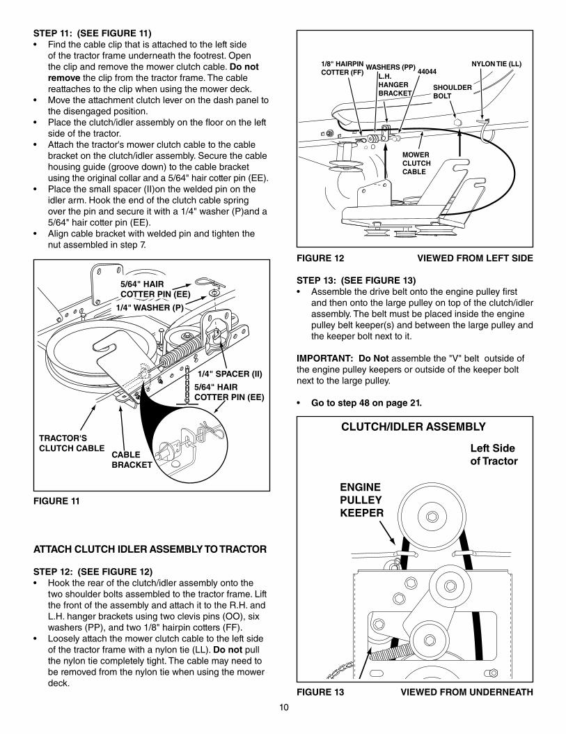
STEP 13: (SEE FIGURE 13)• Assemble the drive belt onto the engine pulley first
and then onto the large pulley on top of the clutch/idler assembly. The belt must be placed inside the engine pulley belt keeper(s) and between the large pulley and the keeper bolt next to it.
IMPORTANT: Do Not assemble the "V" belt outside of the engine pulley keepers or outside of the keeper bolt next to the large pulley.
• Go to step 48 on page 21.
FIGURE 13 VIEWED FROM UNDERNEATH
CLUTCH/IDLER ASSEMBLY
FIGURE 11
ATTACH CLUTCH IDLER ASSEMBLY TO TRACTOR
STEP 12: (SEE FIGURE 12)• Hook the rear of the clutch/idler assembly onto the
two shoulder bolts assembled to the tractor frame. Lift the front of the assembly and attach it to the R.H. and L.H. hanger brackets using two clevis pins (OO), six washers (PP), and two 1/8" hairpin cotters (FF).
• Loosely attach the mower clutch cable to the left side of the tractor frame with a nylon tie (LL). Do not pull the nylon tie completely tight. The cable may need to be removed from the nylon tie when using the mower deck.
STEP 11: (SEE FIGURE 11)• Find the cable clip that is attached to the left side
of the tractor frame underneath the footrest. Open the clip and remove the mower clutch cable. Do not remove the clip from the tractor frame. The cable reattaches to the clip when using the mower deck.
• Move the attachment clutch lever on the dash panel to the disengaged position.
• Place the clutch/idler assembly on the floor on the left side of the tractor.
• Attach the tractor's mower clutch cable to the cable bracket on the clutch/idler assembly. Secure the cable housing guide (groove down) to the cable bracket using the original collar and a 5/64" hair cotter pin (EE).
• Place the small spacer (II)on the welded pin on the idler arm. Hook the end of the clutch cable spring over the pin and secure it with a 1/4" washer (P)and a 5/64" hair cotter pin (EE).
• Align cable bracket with welded pin and tighten the nut assembled in step 7.
L.H. HANGERBRACKET
1/8" HAIRPINCOTTER (FF)
NYLON TIE (LL)WASHERS (PP)44044
SHOULDERBOLT
MOWERCLUTCHCABLE
1/4" SPACER (II)
5/64" HAIRCOTTER PIN (EE)
CABLEBRACKET
TRACTOR'SCLUTCH CABLE
5/64" HAIRCOTTER PIN (EE)
1/4" WASHER (P)
ENGINEPULLEYENGINEPULLEY
Left Sideof Tractor
ENGINEPULLEYKEEPER
KEEPER BOLTIDLERPULLEY
11
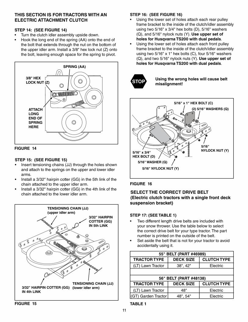
THIS SECTION IS FOR TRACTORS WITH AN ELECTRIC ATTACHMENT CLUTCH
STEP 14: (SEE FIGURE 14)• Turn the clutch idler assembly upside down.• Hook the long end of the spring (AA) onto the end of
the bolt that extends through the nut on the bottom of the upper idler arm. Install a 3/8" hex lock nut (Z) onto the bolt, leaving enough space for the spring to pivot.
FIGURE 14
FIGURE 16
STEP 16: (SEE FIGURE 16)• Using the lower set of holes attach each rear pulley
frame bracket to the inside of the clutch/idler assembly using two 5/16" x 3/4" hex bolts (D), 5/16" washers (Q), and 5/16" nylock nuts (Y). Use upper set of holes for Husqvarna TS200 with dual pedals.
• Using the lower set of holes attach each front pulley frame bracket to the inside of the clutch/idler assembly using two 5/16" x 1" hex bolts (C), four 5/16" washers (Q), and two 5/16" nylock nuts (Y). Use upper set of holes for Husqvarna TS200 with dual pedals.
STEP 15: (SEE FIGURE 15)• Insert tensioning chains (JJ) through the holes shown
and attach to the springs on the upper and lower idler arms.
• Install a 3/32" hairpin cotter (GG) in the 5th link of the chain attached to the upper idler arm.
• Install a 3/32" hairpin cotter (GG) in the 4th link of the chain attached to the lower idler arm.
FIGURE 15
STEP 17: (SEE TABLE 1)• Two different length drive belts are included with
your snow thrower. Use the table below to select the correct drive belt for your type tractor. The part number is printed on the outside of the belt.
• Set aside the belt that is not for your tractor to avoid accidentally using it.
SELECT THE CORRECT DRIVE BELT(Electric clutch tractors with a single front deck suspension bracket)
55" BELT (PART #46989) TRACTOR TYPE DECK SIZE CLUTCH TYPE
(LT) Lawn Tractor 38", 42" Electric
56" BELT (PART #48138) TRACTOR TYPE DECK SIZE CLUTCH TYPE
(LT) Lawn Tractor 48" Electric (GT) Garden Tractor 48", 54" Electric
TABLE 1
3/8" HEXLOCK NUT (Z)
SPRING (AA)
ATTACHLONGEND OFSPRINGHERE
TENSIONING CHAIN (JJ)(lower idler arm)
TENSIONING CHAIN (JJ)(upper idler arm)
3/32" HAIRPINCOTTER (GG)IN 5th LINK
3/32" HAIRPIN COTTER (GG)IN 4th LINK
5/16" x 1" HEX BOLT (C)
5/16" x 3/4"HEX BOLT (D)
5/16" NYLOCK NUT (Y)
5/16" WASHER (Q)
5/16"NYLOCK NUT (Y)
(2) 5/16" WASHERS (Q)
STOP Using the wrong holes will cause belt misalignment!
12
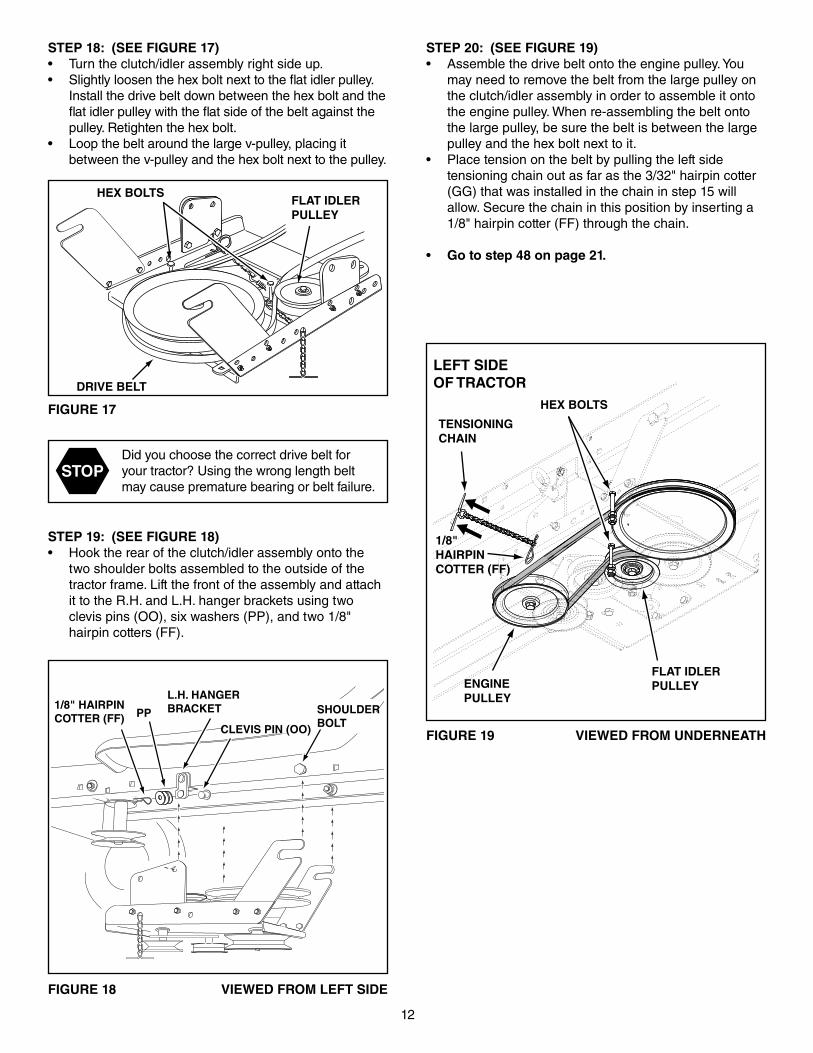
STEP 19: (SEE FIGURE 18)• Hook the rear of the clutch/idler assembly onto the
two shoulder bolts assembled to the outside of the tractor frame. Lift the front of the assembly and attach it to the R.H. and L.H. hanger brackets using two clevis pins (OO), six washers (PP), and two 1/8" hairpin cotters (FF).
FIGURE 18 VIEWED FROM LEFT SIDE
FIGURE 19 VIEWED FROM UNDERNEATH
FIGURE 17
STEP 18: (SEE FIGURE 17)• Turn the clutch/idler assembly right side up.• Slightly loosen the hex bolt next to the flat idler pulley.
Install the drive belt down between the hex bolt and the flat idler pulley with the flat side of the belt against the pulley. Retighten the hex bolt.
• Loop the belt around the large v-pulley, placing it between the v-pulley and the hex bolt next to the pulley.
STOPDid you choose the correct drive belt for your tractor? Using the wrong length belt may cause premature bearing or belt failure.
DRIVE BELT
FLAT IDLERPULLEY
HEX BOLTS
1/8" HAIRPINCOTTER (FF)
L.H. HANGERBRACKETPP
CLEVIS PIN (OO)
SHOULDERBOLT
1/8"HAIRPINCOTTER (FF)
ENGINEPULLEY
HEX BOLTS
FLAT IDLERPULLEY
TENSIONINGCHAIN
LEFT SIDEOF TRACTOR
STEP 20: (SEE FIGURE 19)• Assemble the drive belt onto the engine pulley. You
may need to remove the belt from the large pulley on the clutch/idler assembly in order to assemble it onto the engine pulley. When re-assembling the belt onto the large pulley, be sure the belt is between the large pulley and the hex bolt next to it.
• Place tension on the belt by pulling the left side tensioning chain out as far as the 3/32" hairpin cotter (GG) that was installed in the chain in step 15 will allow. Secure the chain in this position by inserting a 1/8" hairpin cotter (FF) through the chain.
• Go to step 48 on page 21.
13
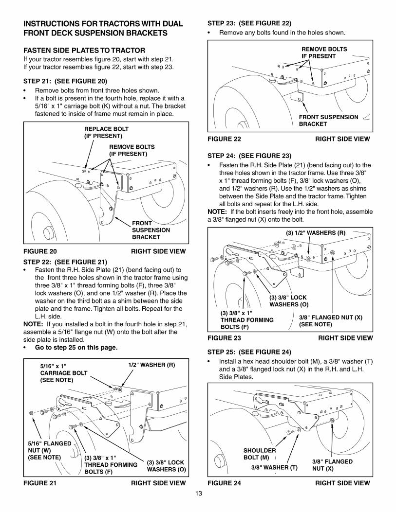
STEP 22: (SEE FIGURE 21)• Fasten the R.H. Side Plate (21) (bend facing out) to
the front three holes shown in the tractor frame using three 3/8" x 1" thread forming bolts (F), three 3/8" lock washers (O), and one 1/2" washer (R). Place the washer on the third bolt as a shim between the side plate and the frame. Tighten all bolts. Repeat for the L.H. side.
NOTE: If you installed a bolt in the fourth hole in step 21, assemble a 5/16" flange nut (W) onto the bolt after the side plate is installed.• Go to step 25 on this page.
(3) 3/8" x 1"THREAD FORMINGBOLTS (F)
5/16" FLANGEDNUT (W)(SEE NOTE)
(3) 3/8" LOCKWASHERS (O)
1/2" WASHER (R)5/16" x 1"CARRIAGE BOLT(SEE NOTE)
FIGURE 21 RIGHT SIDE VIEW
FRONT SUSPENSIONBRACKET
REMOVE BOLTS IF PRESENT
FIGURE 22 RIGHT SIDE VIEW
STEP 23: (SEE FIGURE 22)• Remove any bolts found in the holes shown.
STEP 21: (SEE FIGURE 20)• Remove bolts from front three holes shown.• If a bolt is present in the fourth hole, replace it with a
5/16" x 1" carriage bolt (K) without a nut. The bracket fastened to inside of frame must remain in place.
FRONTSUSPENSIONBRACKET
REPLACE BOLT(IF PRESENT)
REMOVE BOLTS(IF PRESENT)
FIGURE 20 RIGHT SIDE VIEW
INSTRUCTIONS FOR TRACTORS WITH DUAL FRONT DECK SUSPENSION BRACKETS
FASTEN SIDE PLATES TO TRACTORIf your tractor resembles figure 20, start with step 21. If your tractor resembles figure 22, start with step 23.
STEP 25: (SEE FIGURE 24)• Install a hex head shoulder bolt (M), a 3/8" washer (T)
and a 3/8" flanged lock nut (X) in the R.H. and L.H. Side Plates.
FIGURE 24 RIGHT SIDE VIEW
3/8" WASHER (T)
SHOULDER BOLT (M)
3/8" FLANGEDNUT (X)
STEP 24: (SEE FIGURE 23)• Fasten the R.H. Side Plate (21) (bend facing out) to the
three holes shown in the tractor frame. Use three 3/8" x 1" thread forming bolts (F), 3/8" lock washers (O), and 1/2" washers (R). Use the 1/2" washers as shims between the Side Plate and the tractor frame. Tighten all bolts and repeat for the L.H. side.
NOTE: If the bolt inserts freely into the front hole, assemble a 3/8" flanged nut (X) onto the bolt.
(3) 3/8" x 1"THREAD FORMINGBOLTS (F)
(3) 3/8" LOCKWASHERS (O)
3/8" FLANGED NUT (X)(SEE NOTE)
(3) 1/2" WASHERS (R)
FIGURE 23 RIGHT SIDE VIEW
14
FIGURE 28 RIGHT SIDE VIEW
INSTALLING HANGER BRACKETS For better clearance, lower the tractor's suspension arms using the attachment lift lever.
STEP 26: (SEE FIGURE 25 or 26)On Tractors With Foot Rest Brackets• Remove the bolt and nut that fasten the L.H. and R.H.
foot rest brackets to the frame.• Attach the L.H. Hanger Bracket (18) (marked "L")
to the inside of the tractor frame using two 3/8" x 1" carriage bolts (H) and 3/8" flanged nuts (X). Bolt heads go on inside of tractor frame. Repeat for the R.H. side.
FIGURE 26 LEFT SIDE VIEW
FIGURE 25 LEFT SIDE VIEW
On Tractors Without Foot Rest Brackets• Find the empty hole beneath the foot rest. Attach the
L.H. Hanger Bracket (marked "L") to the inside of the frame using a 3/8" x 1" carriage bolt and a 3/8" flanged nut. Bolt head goes on inside of tractor frame. Repeat for the R.H. side.
STEP 28: (SEE FIGURE 28)• Assemble a shoulder bolt (M)and 3/8" flanged nut (X)
to the R.H. side of the tractor frame, using the first empty hole to the rear of the R.H. hanger bracket (19). Bolt goes on inside of frame.
FIGURE 27 LEFT SIDE VIEW
INSTALLING SHOULDER BOLTS
STEP 27: (SEE FIGURE 27)• Remove the bolt, washer and nut which fasten the
sway bar bracket to the L.H. side of the tractor frame. Replace with a shoulder bolt (M) and a 3/8" flanged nut (X). Bolt goes on inside of frame.
BOLT REMOVEDFROM THIS HOLE
SWAY BARBRACKET
SHOULDER BOLT (M)
3/8"FLANGED
NUT (X)
3/8" x 1"CARRIAGEBOLT (H)
3/8" FLANGED NUT (X)
L.H. HANGERBRACKET (18)
SUSPENSION ARM
SHOULDER BOLT (M)
3/8"FLANGEDNUT (X)
R.H. HANGER BRACKET (19)
BOLT REMOVEDFROM THIS HOLE
3/8" x 1"CARRIAGEBOLT (H)
3/8" FLANGEDNUT (X)
L.H. HANGERBRACKET (18)
SUSPENSION ARM
15
INSTALLING CLUTCH/IDLER ASSEMBLY This section covers the installation of the Clutch/Idler assembly to tractors with attachment clutches that are either rod operated (p. 15), cable operated (p. 17) or electric (p. 19). Use the appropriate instructions for your tractor.
ROD OPERATED MANUAL ATTACHMENT CLUTCH
STEP 29: (SEE FIGURE 29)• Move the attachment clutch lever on the dash panel to
the disengaged (down) position.• Screw the trunnion (DD) onto the end of the snow
thrower engagement rod (5).• Locate the clutch arm (where the mower clutch rod
was connected) underneath the right hand side the tractor, just to the inside of the suspension arm. If there is an extension attached to the clutch lever, the extension, bolt and nut must be removed and stored with the mower deck.
IMPORTANT: Re-attach the extension to the clutch lever before reinstalling the mower deck.
• Position the engagement rod (5) to the inside of the clutch arm and insert the drilled end of the rod through the arm. Secure with a 5/64" hairpin cotter (EE).
FIGURE 29 RIGHT SIDE VIEW
ENGAGEMENT ROD (5)
5/64" HAIRPINCOTTER (EE)
TRACTOR'S CLUTCH ARM
SUSPENSION ARM
TRUNNION (DD)
REMOVE EXTENSION,BOLT AND NUT(IF PRESENT)
STEP 30: (SEE FIGURE 30)• Attach the two rear pulley frame brackets (10) to the
inside of the clutch/idler assembly using two 5/16" x 1" hex bolts (C), eight 5/16" washers (Q), and two 5/16" nylock nuts (Y) for each bracket.
• Attach the two front pulley frame brackets to the inside of the clutch/idler assembly using two 5/16" x 3/4" hex bolts (D), 5/16" washers (Q), and 5/16" nylock nuts (Y)for each bracket. Add extra washers if needed.
FIGURE 30
FIGURE 31
STOPDid you choose the correct drive belt for your tractor? Using the wrong length belt may cause premature bearing or belt failure.
STEP 31: (SEE FIGURE 31)• Two different length drive belts are included with
your snow thrower. Tractors with manual attachment clutches and dual front deck suspension brackets use the 55" drive belt with #46989 printed on the outside of the belt. DO NOT USE the other belt.
• Slightly loosen the hex bolt next to the flat idler pulley. Install the drive belt down between the hex bolt and the flat idler pulley with the flat side of the belt against the pulley. Retighten the hex bolt.
• Loop the belt around the large v-pulley, placing it between the v-pulley and the hex bolt next to the pulley.
TENSIONING CHAIN (JJ)(lower idler arm)
5/16" x 3/4"HEX BOLT (D)
5/16" x 1"HEX BOLT (C)
5/16" NYLOCK NUT (Y)
5/16"WASHER (Q)
(4) 5/16" WASHERS (Q)
3/32" HAIRPINCOTTER (GG)IN 4th LINK
#46989DRIVE BELT
FLAT IDLERPULLEY
HEX BOLTS
• Insert a tensioning chain through the hole shown and attach it to the spring on the lower idler arm.
• Install a 3/32" hairpin cotter (GG) in the 4th link of the chain.
16
FIGURE 33 RIGHT SIDE VIEW
FIGURE 32 RIGHT SIDE VIEW
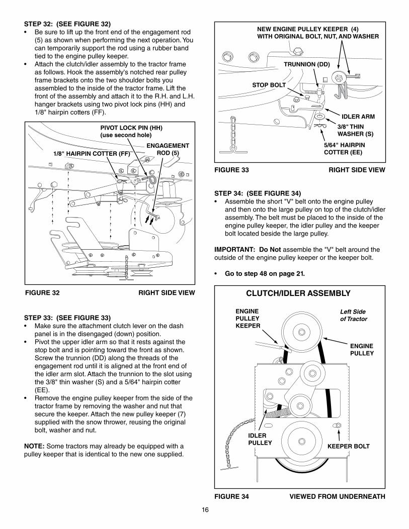
STEP 33: (SEE FIGURE 33)• Make sure the attachment clutch lever on the dash
panel is in the disengaged (down) position.• Pivot the upper idler arm so that it rests against the
stop bolt and is pointing toward the front as shown. Screw the trunnion (DD) along the threads of the engagement rod until it is aligned at the front end of the idler arm slot. Attach the trunnion to the slot using the 3/8" thin washer (S) and a 5/64" hairpin cotter (EE).
• Remove the engine pulley keeper from the side of the tractor frame by removing the washer and nut that secure the keeper. Attach the new pulley keeper (7)supplied with the snow thrower, reusing the original bolt, washer and nut.
NOTE: Some tractors may already be equipped with apulley keeper that is identical to the new one supplied.
IDLER ARM
5/64" HAIRPINCOTTER (EE)
STOP BOLT
3/8" THINWASHER (S)
NEW ENGINE PULLEY KEEPER (4) WITH ORIGINAL BOLT, NUT, AND WASHER
TRUNNION (DD)
STEP 34: (SEE FIGURE 34)• Assemble the short "V" belt onto the engine pulley
and then onto the large pulley on top of the clutch/idler assembly. The belt must be placed to the inside of the engine pulley keeper, the idler pulley and the keeper bolt located beside the large pulley.
IMPORTANT: Do Not assemble the "V" belt around the outside of the engine pulley keeper or the keeper bolt.
• Go to step 48 on page 21.
FIGURE 34 VIEWED FROM UNDERNEATH
CLUTCH/IDLER ASSEMBLY
STEP 32: (SEE FIGURE 32)• Be sure to lift up the front end of the engagement rod
(5) as shown when performing the next operation. You can temporarily support the rod using a rubber band tied to the engine pulley keeper.
• Attach the clutch/idler assembly to the tractor frame as follows. Hook the assembly's notched rear pulley frame brackets onto the two shoulder bolts you assembled to the inside of the tractor frame. Lift the front of the assembly and attach it to the R.H. and L.H. hanger brackets using two pivot lock pins (HH) and 1/8" hairpin cotters (FF).
PIVOT LOCK PIN (HH)(use second hole)
1/8" HAIRPIN COTTER (FF)ENGAGEMENT
ROD (5)
ENGINE PULLEY
KEEPER BOLT
IDLER PULLEY
ENGINE PULLEY KEEPER
Left Side of Tractor
17
FIGURE 36
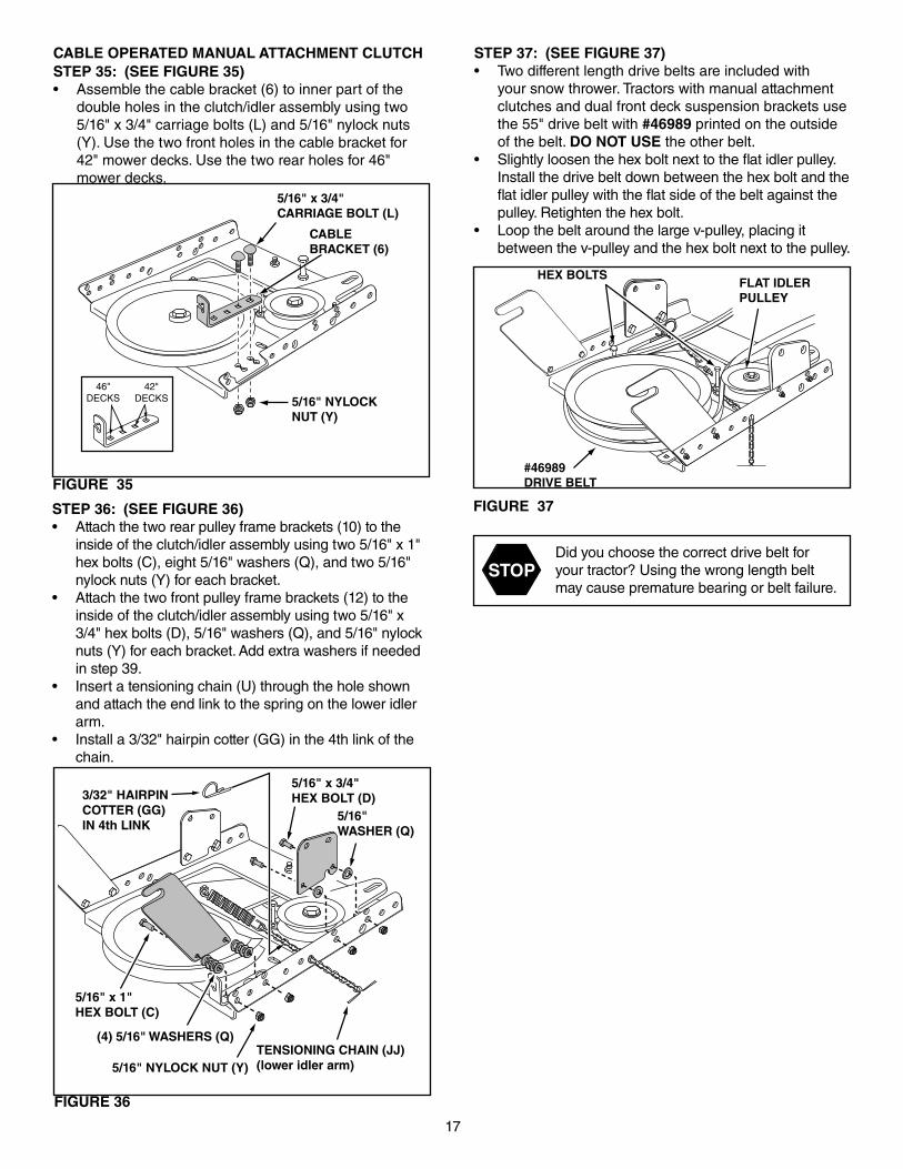
STEP 35: (SEE FIGURE 35)• Assemble the cable bracket (6) to inner part of the
double holes in the clutch/idler assembly using two 5/16" x 3/4" carriage bolts (L) and 5/16" nylock nuts (Y). Use the two front holes in the cable bracket for 42" mower decks. Use the two rear holes for 46" mower decks.
STEP 36: (SEE FIGURE 36)• Attach the two rear pulley frame brackets (10) to the
inside of the clutch/idler assembly using two 5/16" x 1" hex bolts (C), eight 5/16" washers (Q), and two 5/16" nylock nuts (Y) for each bracket.
• Attach the two front pulley frame brackets (12) to the inside of the clutch/idler assembly using two 5/16" x 3/4" hex bolts (D), 5/16" washers (Q), and 5/16" nylock nuts (Y) for each bracket. Add extra washers if needed in step 39.
• Insert a tensioning chain (U) through the hole shown and attach the end link to the spring on the lower idler arm.
• Install a 3/32" hairpin cotter (GG) in the 4th link of the chain.
FIGURE 35
CABLE OPERATED MANUAL ATTACHMENT CLUTCH
FIGURE 37
STEP 37: (SEE FIGURE 37)• Two different length drive belts are included with
your snow thrower. Tractors with manual attachment clutches and dual front deck suspension brackets use the 55" drive belt with #46989 printed on the outside of the belt. DO NOT USE the other belt.
• Slightly loosen the hex bolt next to the flat idler pulley. Install the drive belt down between the hex bolt and the flat idler pulley with the flat side of the belt against the pulley. Retighten the hex bolt.
• Loop the belt around the large v-pulley, placing it between the v-pulley and the hex bolt next to the pulley.
STOPDid you choose the correct drive belt for your tractor? Using the wrong length belt may cause premature bearing or belt failure.
CABLEBRACKET (6)
5/16" x 3/4"CARRIAGE BOLT (L)
5/16" NYLOCK NUT (Y)
42"DECKS
46"DECKS
TENSIONING CHAIN (JJ)(lower idler arm)
5/16" x 3/4"HEX BOLT (D)
5/16" x 1"HEX BOLT (C)
5/16" NYLOCK NUT (Y)
5/16"WASHER (Q)
(4) 5/16" WASHERS (Q)
3/32" HAIRPINCOTTER (GG)IN 4th LINK
#46989DRIVE BELT
FLAT IDLERPULLEY
HEX BOLTS
18FIGURE 40 VIEWED FROM UNDERNEATH
FIGURE 39
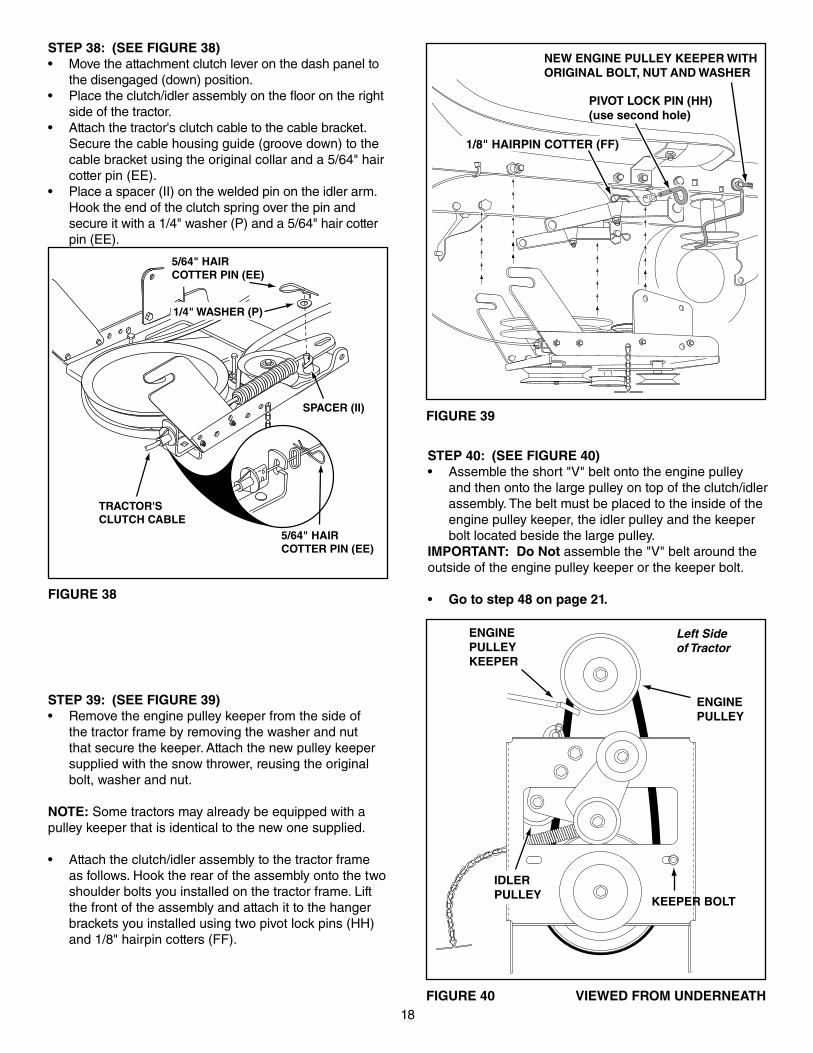
STEP 40: (SEE FIGURE 40)• Assemble the short "V" belt onto the engine pulley
and then onto the large pulley on top of the clutch/idler assembly. The belt must be placed to the inside of the engine pulley keeper, the idler pulley and the keeper bolt located beside the large pulley.
IMPORTANT: Do Not assemble the "V" belt around the outside of the engine pulley keeper or the keeper bolt.
• Go to step 48 on page 21.
STEP 39: (SEE FIGURE 39)• Remove the engine pulley keeper from the side of
the tractor frame by removing the washer and nut that secure the keeper. Attach the new pulley keeper supplied with the snow thrower, reusing the original bolt, washer and nut.
NOTE: Some tractors may already be equipped with apulley keeper that is identical to the new one supplied.
• Attach the clutch/idler assembly to the tractor frame as follows. Hook the rear of the assembly onto the two shoulder bolts you installed on the tractor frame. Lift the front of the assembly and attach it to the hanger brackets you installed using two pivot lock pins (HH) and 1/8" hairpin cotters (FF).
FIGURE 38
STEP 38: (SEE FIGURE 38)• Move the attachment clutch lever on the dash panel to
the disengaged (down) position.• Place the clutch/idler assembly on the floor on the right
side of the tractor.• Attach the tractor's clutch cable to the cable bracket.
Secure the cable housing guide (groove down) to the cable bracket using the original collar and a 5/64" hair cotter pin (EE).
• Place a spacer (II) on the welded pin on the idler arm. Hook the end of the clutch spring over the pin and secure it with a 1/4" washer (P) and a 5/64" hair cotter pin (EE).
5/64" HAIRCOTTER PIN (EE)
1/4" WASHER (P)
TRACTOR'SCLUTCH CABLE
5/64" HAIRCOTTER PIN (EE)
SPACER (II)
NEW ENGINE PULLEY KEEPER WITHORIGINAL BOLT, NUT AND WASHER
PIVOT LOCK PIN (HH)(use second hole)
1/8" HAIRPIN COTTER (FF)
ENGINE PULLEY
KEEPER BOLT
IDLER PULLEY
ENGINE PULLEY KEEPER
Left Side of Tractor
19
ELECTRIC ATTACHMENT CLUTCHES
FIGURE 42
FIGURE 43 VIEW OF BOTTOM
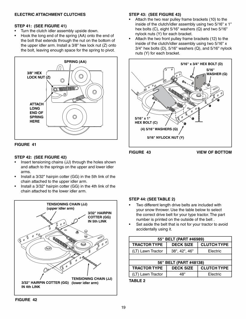
STEP 43: (SEE FIGURE 43)• Attach the two rear pulley frame brackets (10) to the
inside of the clutch/idler assembly using two 5/16" x 1" hex bolts (C), eight 5/16" washers (Q) and two 5/16" nylock nuts (Y) for each bracket.
• Attach the two front pulley frame brackets (12) to the inside of the clutch/idler assembly using two 5/16" x 3/4" hex bolts (D), 5/16" washers (Q), and 5/16" nylock nuts (Y) for each bracket.
STEP 44: (SEE TABLE 2)• Two different length drive belts are included with
your snow thrower. Use the table below to select the correct drive belt for your type tractor. The part number is printed on the outside of the belt .
• Set aside the belt that is not for your tractor to avoid accidentally using it.
55" BELT (PART #46989) TRACTOR TYPE DECK SIZE CLUTCH TYPE
56" BELT (PART #48138) TRACTOR TYPE DECK SIZE CLUTCH TYPE
(LT) Lawn Tractor 48" Electric
(LT) Lawn Tractor 38", 42", 46" Electric
TABLE 2
STEP 41: (SEE FIGURE 41)• Turn the clutch idler assembly upside down.• Hook the long end of the spring (AA) onto the end of
the bolt that extends through the nut on the bottom of the upper idler arm. Install a 3/8" hex lock nut (Z) onto the bolt, leaving enough space for the spring to pivot.
FIGURE 41
STEP 42: (SEE FIGURE 42)• Insert tensioning chains (JJ) through the holes shown
and attach to the springs on the upper and lower idler arms.
• Install a 3/32" hairpin cotter (GG) in the 5th link of the chain attached to the upper idler arm.
• Install a 3/32" hairpin cotter (GG) in the 4th link of the chain attached to the lower idler arm.
3/8" HEXLOCK NUT (Z)
SPRING (AA)
ATTACHLONGEND OFSPRINGHERE
TENSIONING CHAIN (JJ)(lower idler arm)
TENSIONING CHAIN (JJ)(upper idler arm)
3/32" HAIRPINCOTTER (GG)IN 5th LINK
3/32" HAIRPIN COTTER (GG)IN 4th LINK
5/16" x 3/4" HEX BOLT (D)
5/16" x 1"HEX BOLT (C)
5/16" NYLOCK NUT (Y)
5/16"WASHER (Q)
(4) 5/16" WASHERS (Q)
20
FIGURE 46 VIEWED FROM UNDERNEATH
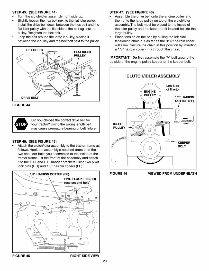
STEP 47: (SEE FIGURE 46)• Assemble the drive belt onto the engine pulley and
then onto the large pulley on top of the clutch/idler assembly. The belt must be placed to the inside of the idler pulley and the keeper bolt located beside the large pulley.
• Place tension on the belt by pulling the left side tensioning chain out as far as the 3/32" hairpin cotter will allow. Secure the chain in this position by inserting a 1/8" hairpin cotter (FF) through the chain.
IMPORTANT: Do Not assemble the "V" belt around the outside of the engine pulley keeper or the keeper bolt.
STEP 46: (SEE FIGURE 45)• Attach the clutch/idler assembly to the tractor frame as
follows. Hook the assembly's notched arms onto the two shoulder bolts you assembled to the inside of the tractor frame. Lift the front of the assembly and attach it to the R.H. and L.H. hanger brackets using two pivot lock pins (HH) and 1/8" hairpin cotters (FF).
FIGURE 45 RIGHT SIDE VIEW
CLUTCH/IDLER ASSEMBLY
FIGURE 44
STOPDid you choose the correct drive belt for your tractor? Using the wrong length belt may cause premature bearing or belt failure.
STEP 45: (SEE FIGURE 44)• Turn the clutch/idler assembly right side up.• Slightly loosen the hex bolt next to the flat idler pulley.
Install the drive belt down between the hex bolt and the flat idler pulley with the flat side of the belt against the pulley. Retighten the hex bolt.
• Loop the belt around the large v-pulley, placing it between the v-pulley and the hex bolt next to the pulley.
DRIVE BELT
FLAT IDLERPULLEY
HEX BOLTS
PIVOT LOCK PIN (HH)(use second hole)
1/8" HAIRPIN COTTER (FF)
1/8" HAIRPINCOTTER (FF)
ENGINEPULLEYENGINEPULLEY
Left Sideof Tractor
KEEPERBOLT
IDLERPULLEY
21
STEP 48: (SEE FIGURE 47)• Place the lift handle (2) into the lift bracket on the right
side of the snow thrower. Fasten the handle to the bracket using two 5/16" x 1-3/4" hex bolts (B) and 5/16" nylock nuts (Y).
FIGURE 48 RIGHT SIDE VIEW
NOTE: Be sure the lift release cable's plastic covering stays inserted into the trigger assembly for the next step.
STEP 49: (SEE FIGURE 48)• Push the lift handle down into the locked position.
Insert the end of the cable wire into the hole in the lift rod. Place the threaded fitting into the slot in the lift bracket, with one hex nut above and one hex nut and the lock washer below the slot. Tighten the nuts, adjusting them to eliminate slack in the cable wire. Refer also to the Service and Adjustments section on page 27 in this manual.
HINT: For easier assembly of the lift release cable, tilt the snow thrower forward onto the spiral auger.
FIGURE 47 RIGHT SIDE VIEW
5/16" NYLOCK NUT
5/16" x 1-3/4" HEX BOLT (B)
LIFT HANDLE (2)
ASSEMBLY OF THE SNOW THROWER STEP 50: (SEE FIGURE 49)• Tilt the snow thrower back down to the ground.• Remove the nylon tie which fastens the auger
drive belt to the discharge housing, leaving the belt assembled around the pulleys.
• Remove the nylon tie which fastens the chute crank rod to the crank rod support tube.
• Assemble the crank rod support tube (3) to the bracket on the left side of the discharge housing using two 5/16" x 1-1/4" carriage bolts (J), and 5/16" nylock nuts (Y).
5/16" NYLOCK NUT (Y)
5/16" x 1-1/4"CARRIAGE BOLT (J)
CRANK RODSUPPORT TUBE (3)
DISCHARGEHOUSING
FIGURE 49 LEFT SIDE VIEW
LIFT RELEASE CABLE
HEX NUT
LOCKWASHER
HEX NUT
CABLEWIRE
LIFTROD
TRIGGERASSEMBLY
FIGURE 50
STEP 51: (SEE FIGURE 50)• Install the plug (NN) into the end of the crank support
tube.• Attach the chute tilt control assembly (8) to the top
side of the crank rod support tube using two 5/16" x 1-3/4" carriage bolts (I), bowed washers (U) and 5/16" nylock nuts (Y).
CHUTE TILT CONTROLASSEMBLY (8)
5/16" x 1-3/4" CARRIAGE BOLT (I)
BOWED WASHER (U)
5/16" NYLOCK NUT (Y)
PLUG (NN)
22
5/16" NYLOCK NUT (Y)
CHUTE CRANKBRACKET
5/16" WASHER (Q)
CHUTECRANKROD
RODSUPPORTBRACKET
5/16" x 1"CARRIAGE BOLT (K)
SPIRAL
FIGURE 52 LEFT SIDE VIEW
FIGURE 53 RIGHT SIDE VIEW
CHUTE KEEPER (BB)
CHUTE SPACER (CC)
ANTI-ROTATIONBRACKET (11)
1/4" FLANGEDLOCK NUT (V)
1/4" FLATWASHER (P)
1/4" x 1" HEX BOLT (E)
GREASEDSURFACE
FLANGE
STEP 54: (SEE FIGURE 53)• Coat the top of the ring around the discharge opening
with general purpose grease.• Place the discharge chute (facing forward) onto the
ring. Place the anti-rotation bracket (11) on top of the chute flange, aligning it with the holes on the right hand side of the flange. Attach the three chute spacers (CC) and chute keepers (BB) to the bottom of the flange using six 1/4" x 1" hex bolts (E), 1/4" flat washers (P) and 1/4" flanged lock nuts (V). Tighten carefully so that the nuts are snug but do not dig into the plastic chute keepers.
• Position the crank rod spiral (see figure 51) so that it does not rub against the bottoms of the notches in the chute flange. Tighten the nuts.
• Turn the crank rod to check if the chute rotates freely. If not, loosen the bolts and nuts that attach the chute to the flange by 1/4 turn each.
• Secure the control cables to the crank rod support tube using a nylon tie (LL).
STEP 53: (SEE FIGURE 52)• Attach the chute crank rod assembly brackets to
the plastic bracket on the left side of the discharge housing. Align the chute crank bracket beneath the rod support bracket and assemble both to the plastic bracket using two 5/16" x 1" carriage bolts (K), 5/16" washers (Q) and 5/16" nylock nuts (Y). Do not tighten yet.
CHUTE CRANK ROD (4)
CHUTE TILT CONTROLASSEMBLY (8)
GRIP (MM)
FIGURE 51 RIGHT SIDE VIEW
STEP 52: (SEE FIGURE 51)• Install the chute crank rod (4) into the plastic bushing
in the chute tilt control assembly (8). • Install the grip (MM) onto the chute crank rod (4).
23
STEP 55: (SEE FIGURE 54)• Place the snow thrower on a flat, level surface.• Extend the auger belt out behind the snow thrower,
keeping the belt assembled to the snow thrower pulleys. • Roll the tractor up behind the snow thrower, centering
it between the snow thrower's mounting plates.• Raise the rear of the snow thrower by lifting up on
the lift handle until the notches in the mounting plates align with the shoulder bolts in the tractor's side plates. Guide the bolts into the notches.
• Delay installing the clevis pins (QQ) until you have assembled the belt as instructed in steps 56 and 57.
ATTACHING SNOW THROWER TO TRACTOR
STEP 56: (SEE FIGURE 55)• The auger belt comes pre-assembled to the pulleys on
the snow thrower housing. Make sure the belt passes over the top of the auger pulley and then twists 1/4 turn to pass underneath each side idler pulley. The "V" side of the belt must mate with the grooves of the pulleys.
IDLER PULLEY
AUGER PULLEYTWIST 1/4 TURN
TWIST 1/4 TURN
IDLER PULLEY
FIGURE 55
FIGURE 54 RIGHT SIDE VIEW
BELT ROUTING DIAGRAM
ENGINE PULLEY
1/8" HAIRPINCOTTER (FF)
MOUNTINGPLATE
SIDE PLATE
CLEVIS PIN1/2" x 7/8" (QQ)
SHOULDERBOLT
FIGURE 56 VIEWED FROM UNDERNEATH
STEP 57: (SEE FIGURE 56)• Push the lift handle down to increase slack in the belt.• Swing the lower idler arm over to the left side.• Slightly loosen the belt keeper bolts located beside
the idler arm V-pulley and the rear V-pulley.• Place the auger belt around the rear V-pulley and
between the two pulleys on the idler arm. The "V" side of the belt must be seated in the grooves of the V-pulleys.
• Retighten the two keeper bolts.
LEFT SIDEOF TRACTOR
KEEPERBOLT
IDLER ARM V-PULLEY
IDLER ARMFLAT PULLEY
KEEPERBOLT
NUT
24
REAR REFLECTORS (KK)
ATTACH REFLECTORS TO REAR FENDERSTEP 60: (SEE FIGURE 59)• If your tractor is not equipped with rear reflectors,
assemble the supplied rear reflectors (KK) to the rear fender. Place the reflectors as close to the bottom of the fender and as far apart as the shape of the fender will allow.
FIGURE 59
CHECKLIST
Before you operate your snow thrower, please review the following checklist to help ensure that you will obtain the best performance from your snow thrower.
1. All assembly instructions have been completed with all bolts and nuts properly tightened.
2. Check the engine belt and the auger belt. Make sure they are routed properly around pulleys and inside all belt keepers.
3. Check discharge chute for proper rotation.
4. Check operation of tilt control for upper chute.
5. Verify that the lift handle will lock into and release from the raised transport position. (Refer to the Service and Adjustments section.)
6. Check skid shoe adjustment. (Refer to the Service and Adjustments section.)
Operating instructions begin on page 25.
SETTING THE AUGER BELT TENSION
STEP 58: (SEE FIGURE 57)• Pull the tensioning chain until it is extended out as
far as the 3/32" hairpin cotter installed in the chain will allow. Install a 1/8" hairpin cotter (FF) through the chain to secure it in the extended position.
NOTE: After pulling the chain out, check to make sure the belt does not rub against the keeper bolts. If the belt rubs, slightly loosen the bolts, move them as far from the pulleys as possible, and retighten.
FIGURE 57 VIEWED FROM UNDERNEATH
RIGHT SIDE OF TRACTOR
NYLOCK NUT
LIFT LINK
3"- 4"SCRAPER PLATE
FIGURE 58 VIEWED FROM LEFT SIDE
SETTING THE SNOW THROWER LIFT HEIGHT
STEP 59: (SEE FIGURE 58)• Adjust the nut on the lift link found on each side of the
snow thrower, so that the auger housing is level when raised, and the scraper plate has approximately 3" to 4" of ground clearance.
1/8" HAIRPIN COTTER (FF)
KEEPER BOLTS
AUGER BELT
25
OPERATION
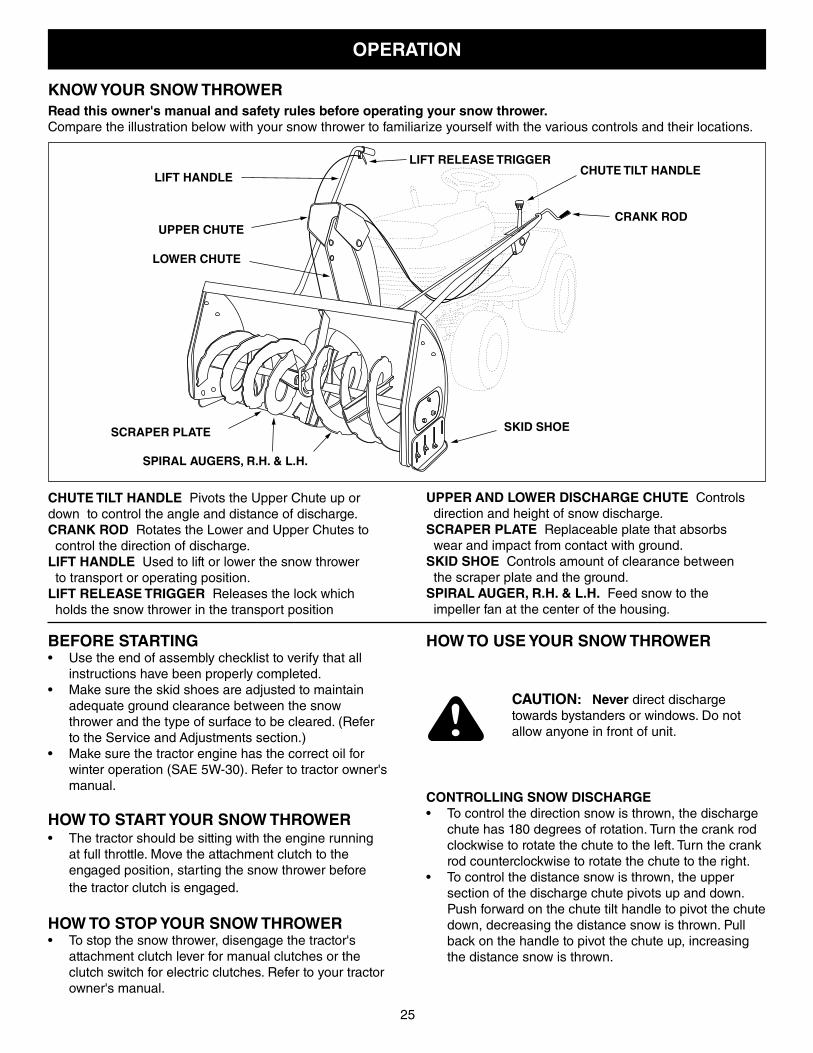
KNOW YOUR SNOW THROWERRead this owner's manual and safety rules before operating your snow thrower.Compare the illustration below with your snow thrower to familiarize yourself with the various controls and their locations.
CHUTE TILT HANDLE Pivots the Upper Chute up or down to control the angle and distance of discharge.CRANK ROD Rotates the Lower and Upper Chutes to control the direction of discharge.LIFT HANDLE Used to lift or lower the snow thrower to transport or operating position.LIFT RELEASE TRIGGER Releases the lock which holds the snow thrower in the transport position
UPPER AND LOWER DISCHARGE CHUTE Controls direction and height of snow discharge.SCRAPER PLATE Replaceable plate that absorbs wear and impact from contact with ground. SKID SHOE Controls amount of clearance between the scraper plate and the ground.SPIRAL AUGER, R.H. & L.H. Feed snow to the impeller fan at the center of the housing.
BEFORE STARTING• Use the end of assembly checklist to verify that all
instructions have been properly completed.• Make sure the skid shoes are adjusted to maintain
adequate ground clearance between the snow thrower and the type of surface to be cleared. (Refer to the Service and Adjustments section.)
• Make sure the tractor engine has the correct oil for winter operation (SAE 5W-30). Refer to tractor owner's manual.
HOW TO START YOUR SNOW THROWER• The tractor should be sitting with the engine running
at full throttle. Move the attachment clutch to the engaged position, starting the snow thrower before the tractor clutch is engaged.
HOW TO STOP YOUR SNOW THROWER• To stop the snow thrower, disengage the tractor's
attachment clutch lever for manual clutches or the clutch switch for electric clutches. Refer to your tractor owner's manual.
CAUTION: Never direct discharge towards bystanders or windows. Do not allow anyone in front of unit.
CONTROLLING SNOW DISCHARGE • To control the direction snow is thrown, the discharge
chute has 180 degrees of rotation. Turn the crank rod clockwise to rotate the chute to the left. Turn the crank rod counterclockwise to rotate the chute to the right.
• To control the distance snow is thrown, the upper section of the discharge chute pivots up and down. Push forward on the chute tilt handle to pivot the chute down, decreasing the distance snow is thrown. Pull back on the handle to pivot the chute up, increasing the distance snow is thrown.
HOW TO USE YOUR SNOW THROWER
LIFT HANDLE LIFT RELEASE TRIGGER
CRANK ROD
CHUTE TILT HANDLE
UPPER CHUTE
LOWER CHUTE
SPIRAL AUGERS, R.H. & L.H.
SKID SHOE SCRAPER PLATE
26
RAISING AND LOWERING• To raise, push down on the lift handle until the snow
thrower locks in the raised transport position.• To lower, push down slightly on the lift handle and pull
the trigger. With the trigger pulled, slowly lower the snow thrower until it reaches the ground.
CUSTOMER RESPONSIBILITIES• Read and follow the maintenance schedule and the maintenance procedures listed in this section.
Service Dates
Check for loose fasteners X Check scraper and shoes for wear X X Cleaning X Lubrication Section X
MAINTENANCE SCHEDULE Fill in dates as you complete regular service. Before each
use
After e
ach use
Every
seaso
n
Before storage
LUBRICATION• Oil all pivot points on the snow thrower.• Oil the pivot points of the two idler arms on the clutch/
idler assembly.• Apply penetrating oil to the control cables of the
discharge chute.• Apply a good grade of spray lubricant to the trigger
assembly and the chute tilt control assembly.
CAUTION: Do not operate the snow thrower without the rear weight attached to the tractor to provide extra traction and stability.
MAINTENANCE
CHECK SCRAPER AND SHOES FOR WEAR(Refer to figures 60 and 61 on page 27)• The scraper plate and skid shoes on the bottom of the
snow thrower are subject to wear. To prevent damage to the spiral auger housing, replace plate and shoes before wear is excessive.
REMOVING SNOW Snow removal conditions vary greatly from light fluffy snowfall to wet heavy snow. Operating instructions must be flexible to fit the conditions encountered. The operator must adapt the lawn tractor and snow thrower to depth of snow, wind direction, temperature and surface conditions.• Before beginning operation, thoroughly inspect the
area of operation and remove all door mats, sleds, boards, wires and other foreign objects.
• The spiral auger speed is directly related to engine speed. For maximum snow removal and discharge, maintain high engine r.p.m. (full throttle). It is advisable to operate the lawn tractor at a slow ground speed (1st gear) for safe and efficient snow removal.
• In deep, drifted or banked snow it will be necessary to use full throttle and a slow ground speed (1st gear). Drive forward into the snow, depress the tractor's clutch-brake pedal and allow the spiral auger to clear the snow. Repeat this method until a path is cleared. On the second pass, overlap the first enough to allow the snow thrower to handle the snow without repeated stopping and starting of forward motion.
• In extremely deep snow, raise the snow thrower from the ground to remove the top layer and drive forward only until the tractors front tires reach the uncleared bottom layer of snow. Depress the tractor's clutch-brake pedal and allow the spiral auger to clear the snow. Reverse the tractor and lower the snow thrower to the ground. Drive the tractor forward until the snow again becomes too deep. Repeating this process into and out of drifts will eventually clear even the deepest of snow piles.
• If the snow thrower becomes clogged with snow or jammed with a foreign object, disengage the snow thrower immediately and shut off the tractor engine. Unclog the snow thrower before resuming operation.
OPERATING TIPS• Discharge snow down wind whenever possible.• To help prevent snow from sticking to the snow thrower,
allow the snow thrower to reach outdoor temperature before using it. A light coat of wax may also be applied to the inside surface of the snow thrower housing and discharge chute.
• Use tire chains to improve traction.• Use rear wheel weights to improve traction.• Before the first snowfall, remove all stones, sticks and
other objects which could become hidden by the snow. Permanent obstacles should be marked for visibility.
• Overlap each pass slightly to assure complete snow removal.
DANGER: Shut off engine and disengage snow thrower before unclogging discharge chute. Unclog using a wooden stick, not your hands.
27
SERVICE AND ADJUSTMENTS
CAUTION: Before servicing or adjusting the snow thrower, shut off the engine, remove the spark plug wire(s), set the parking brake and remove the key from the tractor ignition.
FIGURE 61
FIGURE 60
REPLACING AUGER BELT• Disengage the tractor's attachment clutch.• Lower the snow thrower to the ground.• Remove the clevis pins. See figure 54 on page 23.• Lock the snow thrower's lift handle in the down
position to decrease belt tension. • Release the spring tension from the auger belt idler
arm on the bottom of the clutch/idler assembly.• Remove the auger drive belt from the clutch/idler
assembly and from the spiral auger housing.• Install new belt over top of large auger drive pulley
and under the two side idler pulleys. Twist the belt 1/4 turn to seat the "V" of the belt in the groove of each idler pulley. Refer to figure 55 on page 23.
• Assemble the belt onto the clutch/idler assembly.
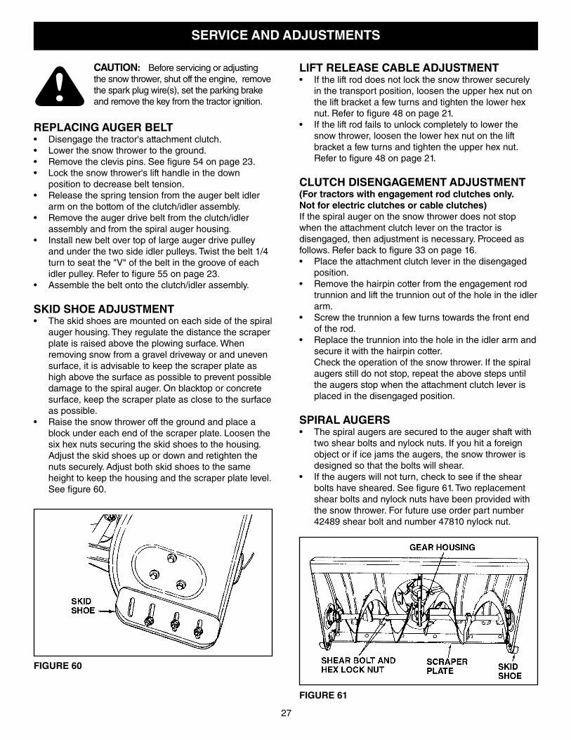
SKID SHOE ADJUSTMENT• The skid shoes are mounted on each side of the spiral
auger housing. They regulate the distance the scraper plate is raised above the plowing surface. When removing snow from a gravel driveway or and uneven surface, it is advisable to keep the scraper plate as high above the surface as possible to prevent possible damage to the spiral auger. On blacktop or concrete surface, keep the scraper plate as close to the surface as possible.
• Raise the snow thrower off the ground and place a block under each end of the scraper plate. Loosen the six hex nuts securing the skid shoes to the housing. Adjust the skid shoes up or down and retighten the nuts securely. Adjust both skid shoes to the same height to keep the housing and the scraper plate level. See figure 60.
LIFT RELEASE CABLE ADJUSTMENT• If the lift rod does not lock the snow thrower securely
in the transport position, loosen the upper hex nut on the lift bracket a few turns and tighten the lower hex nut. Refer to figure 48 on page 21.
• If the lift rod fails to unlock completely to lower the snow thrower, loosen the lower hex nut on the lift bracket a few turns and tighten the upper hex nut. Refer to figure 48 on page 21.
CLUTCH DISENGAGEMENT ADJUSTMENT(For tractors with engagement rod clutches only.Not for electric clutches or cable clutches) If the spiral auger on the snow thrower does not stop when the attachment clutch lever on the tractor is disengaged, then adjustment is necessary. Proceed as follows. Refer back to figure 33 on page 16.• Place the attachment clutch lever in the disengaged
position.• Remove the hairpin cotter from the engagement rod
trunnion and lift the trunnion out of the hole in the idler arm.
• Screw the trunnion a few turns towards the front end of the rod.
• Replace the trunnion into the hole in the idler arm and secure it with the hairpin cotter.
Check the operation of the snow thrower. If the spiral augers still do not stop, repeat the above steps until the augers stop when the attachment clutch lever is placed in the disengaged position.
SPIRAL AUGERS• The spiral augers are secured to the auger shaft with
two shear bolts and nylock nuts. If you hit a foreign object or if ice jams the augers, the snow thrower is designed so that the bolts will shear.
• If the augers will not turn, check to see if the shear bolts have sheared. See figure 61. Two replacement shear bolts and nylock nuts have been provided with the snow thrower. For future use order part number 42489 shear bolt and number 47810 nylock nut.
28
PARTS TO REMOVE AT END OF SEASON• Remove the clutch/idler assembly. (The two hanger
brackets and the two shoulder bolts may be left attached to the tractor frame.)
• Remove the drive belt from the engine pulley.• If you replaced the engine pulley keeper on a manual
attachment clutch tractor, reinstall the tractor's original engine pulley keeper. See figure 33 on page 16 or figure 39 on page 18.
• If you have a rod operated attachment clutch, remove the engagement rod from the tractor's clutch arm. See figure 29 on page 15.
• If a front mounted attachment is to be used, remove the side plates from the tractor. Be sure to assemble bolts back into the empty holes in the tractor frame.
STORAGE RECOMMENDATIONS• Lower the snow thrower to the ground.• Remove the snow thrower from the tractor.• Clean the snow thrower thoroughly. Wash off any salt
deposit which may have dried on the thrower and housing.
• Any bare metal that has become exposed should be painted or coated with a light oil to prevent rust.
• Store in a dry place.
REMOVING THE SPIRAL AUGER HOUSING• Lower the snow thrower to the ground.• Remove the clevis pins. See figure 54 on page 23.• Lock the snow thrower's lift handle in the down
position to decrease belt tension. • Release the spring tension from the auger belt idler
arm on the bottom of the clutch/idler assembly.• Remove the auger drive belt from the clutch/idler
assembly. See figure 56 on page 23.• Pull the spiral auger housing assembly off of the
tractor.
STORAGE
ADJUSTING LIFT HEIGHT, LEVELINGThe snow thrower is equipped with two threaded lift links for adjusting the lift height and leveling of the snow thrower in the raised position.
TO ADJUST THE LIFT HEIGHT:• Raise the snow thrower to the highest position. • Check the clearance between the rear of the idler
bracket (item 39, page 30) and the lift shaft assembly (item 1, page 32). A minimum 1/16" clearance in the raised position is necessary to avoid possible damage to the lift system.
• To increase the lift height, tighten the nuts on the top of both lift links equally until 3" to 4" of ground clearance is obtained. The maximum clearance is approximately 4 inches for GT tractors and 3 inches for YT tractors. Refer to figure 58 on page 24.
TO LEVEL WHEN RAISED:• To keep the snow thrower level in the raised position,
loosen the nut on the top of the lift link on the high side of the snow thrower until the snow thrower is approximately level. It is not critical that the snow thrower be exactly level in the raised position, it will level out when it is lowered to the ground.
29
CAUSEPROBLEM CORRECTION
Clogged discharge chute
Spiral augers don't turn
Snow thrower stalls tractor engine
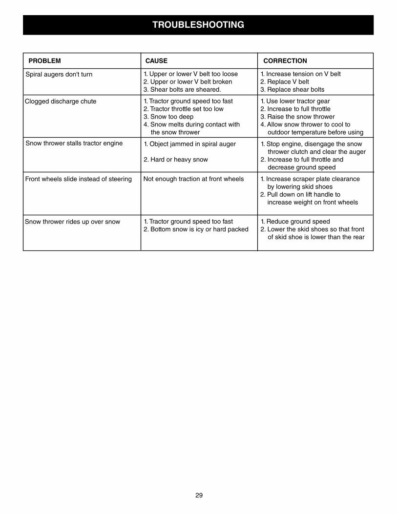
TROUBLESHOOTING
1. Upper or lower V belt too loose 1. Increase tension on V belt2. Upper or lower V belt broken 2. Replace V belt3. Shear bolts are sheared. 3. Replace shear bolts
1. Tractor ground speed too fast 1. Use lower tractor gear2. Tractor throttle set too low 2. Increase to full throttle3. Snow too deep 3. Raise the snow thrower4. Snow melts during contact with 4. Allow snow thrower to cool to the snow thrower outdoor temperature before using
Front wheels slide instead of steering
Snow thrower rides up over snow
1. Object jammed in spiral auger 1. Stop engine, disengage the snow thrower clutch and clear the auger
2. Hard or heavy snow 2. Increase to full throttle and decrease ground speed
Not enough traction at front wheels 1. Increase scraper plate clearance by lowering skid shoes
2. Pull down on lift handle to increase weight on front wheels
1. Tractor ground speed too fast 1. Reduce ground speed2. Bottom snow is icy or hard packed 2. Lower the skid shoes so that front
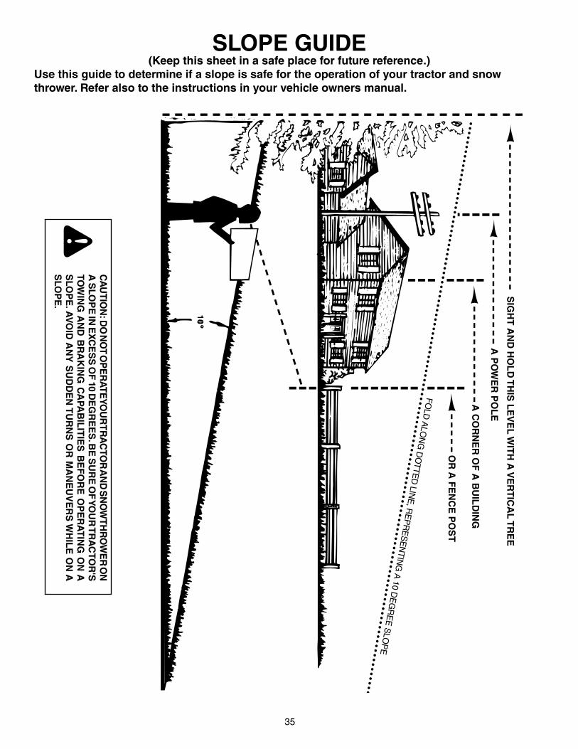
SLOPE GUIDE(Keep this sheet in a safe place for future reference.)
Use this guide to determine if a slope is safe for the operation of your tractor and snow thrower. Refer also to the instructions in your vehicle owners manual.
CA
UTIO
N: D
O N
OT O
PE
RA
TE YO
UR
TRA
CTO
R A
ND
SN
OW
THR
OW
ER
ON
A
SLO
PE
IN E
XC
ES
S O
F 10 D
EG
RE
ES
. BE
SU
RE
OF
YO
UR
TR
AC
TOR
'S
TOW
ING
AN
D B
RA
KIN
G C
APA
BIL
ITIE
S B
EF
OR
E O
PE
RA
TIN
G O
N A
S
LOP
E. A
VO
ID A
NY
SU
DD
EN
TU
RN
S O
R M
AN
EU
VE
RS
WH
ILE
ON
A
SLO
PE
.
A P
OW
ER
PO
LE
A C
OR
NE
R O
F A
BU
ILD
ING
OR
A F
EN
CE
PO
ST
FOLD
ALO
NG
DO
TTED
LINE
, RE
PR
ES
EN
TING
A 10 D
EG
RE
E S
LOP
E
SIG
HT
AN
D H
OL
D T
HIS
LE
VE
L W
ITH
A V
ER
TIC
AL
TR
EE
the fastest way to purchase parts www.speedepart.com