Lucid Operation Manual Ian Fellows Ltd. 2006 – LUCID Operation Manual Revision C Page Issue 023 Page 1 of 67 WARNING LETHAL VOLTAGES MAY BE PRESENT INSIDE THE LUCID ENCLOSURE. GREAT CARE SHOULD BE EXERCISED WHEN THE CASE IS OPENED. LETHAL VOLTAGES MAY BE PRESENT ON THE CONNECTORS, EVEN WHEN THE LUCID ITSELF IS ISOLATED. Product Improvement Policy Ian Fellows Ltd operates a continuous product improvement policy. We are proud of the quality of our products and recognise that improvement is always possible. In our striving for perfection we reserve the right to implement changes to hardware, software and specifications. For these reasons the contents of this manual are subject to change without notice. All efforts have been made to ensure the accuracy of this manual. However, should any errors be detected, Ian Fellows Ltd. would greatly appreciate being informed of them The above notwithstanding, Ian Fellows Ltd. can assume no responsibility for any errors in this manual or their consequences. Note: If you need to consult the factory about any difficulties you may have, please make a note of the LUCID ‘software version number’ (displayed at switch-on), and any relevant parameter values. Have this document handy and quote it’s issue number shown below. Statement on Conformity This Instrument conforms to all appropriate European Community Directives for Process Control Equipment and is designed for operation within an Industrial Environment. (Suitable for Environment as defined in EN 50082-1:1992 and EN 50081-2:1994.) Certificates of conformity can be provided on request In CErt 1 ~ ‘Trade’ mode, LUCID configured with appropriate components, conforms with the Harmonised European Standard EN 45501. This standard is based on a worldwide accepted OIML Recommendation R76 ~ Non Automatic Weighing Instruments. LUCID’s type approval number is EC T2532. In addition, it is built according to a strict ISO9001 Quality Assurance System and complies with EN55022 (Emissions), EN45501 Annex B (Immunity), and both SI2328:1994 and SI3260:1994 Electrical Safety directives. Manual Revision C Issue 023 15/09/2006 6_00J Software. (NO6_00J ) Ian Fellows Ltd. The Old Tannery Lower Keyford. Frome. Somerset. BA11 4AR. www.ianfellows.co.uk
Transcript
L uc id Oper a t io n Ma nu a l
Ian Fellows Ltd. 2006 – LLUUCCIIDD Operation Manual Revision C Page Issue 023 Page 1 of 67
WARNING LETHAL VOLTAGES MAY BE PRESENT INSIDE THE LUCID ENCLOSURE.
GREAT CARE SHOULD BE EXERCISED WHEN THE CASE IS OPENED. LETHAL VOLTAGES MAY BE PRESENT ON THE CONNECTORS,
EVEN WHEN THE LUCID ITSELF IS ISOLATED.
Product Improvement Policy Ian Fellows Ltd operates a continuous product improvement policy. We are proud of the quality of our products and recognise that improvement is always possible. In our striving for perfection we reserve
the right to implement changes to hardware, software and specifications.
For these reasons the contents of this manual are subject to change without notice.
All efforts have been made to ensure the accuracy of this manual. However, should any errors be detected, Ian Fellows Ltd. would greatly appreciate being informed of them
The above notwithstanding, Ian Fellows Ltd. can assume no responsibility for any errors in this
manual or their consequences.
Note: If you need to consult the factory about any difficulties you may have, please make a note of the LUCID ‘software version number’ (displayed at switch-on), and any relevant parameter values. Have this document handy and quote it’s issue number shown below.
Statement on Conformity
This Instrument conforms to all appropriate European Community Directives for Process Control Equipment and is designed for operation within an Industrial Environment. (Suitable for Environment as defined in EN 50082-1:1992 and EN 50081-2:1994.)
Certificates of conformity can be provided on request In CErt 1 ~ ‘Trade’ mode, LUCID configured with appropriate components, conforms with the Harmonised European Standard EN 45501. This standard is based on a worldwide accepted OIML Recommendation R76 ~ Non Automatic Weighing Instruments. LUCID’s type approval number is EC T2532. In addition, it is built according to a strict ISO9001 Quality Assurance System and complies with EN55022 (Emissions), EN45501 Annex B (Immunity), and both SI2328:1994 and SI3260:1994 Electrical Safety directives.
Manual Revision C Issue 023 15/09/2006 6_00J Software. (NO6_00J ⇒)
Ian Fellows Ltd. The Old Tannery Lower Keyford. Frome. Somerset. BA11 4AR. www.ianfellows.co.uk
L uc id Oper a t io n Ma nu a l
Ian Fellows Ltd. 2006 – LLUUCCIIDD Operation Manual Revision C Page Issue 023 Page 2 of 67
Contents
Contents 2
1. GETTING STARTED 4 1.1 Front Panel 4 1.2 Power Connection 5 1.3 Loadcell Connection 5 1.4 Switching on 7
CALIBRATE SWITCH ACCESS & LOCATION 9 2.2 dISP ~ Display Countby and Decimal Point ( ‘e’ ) 9 2.3 toP ~ Maximum Display Capacity ( ‘max’ ) 10 2.4 FILt ~ Filter Band Parameter 10 2.7 CALAt ~ Enter Span Calibration Weight 11 2.8 CAL ~ Span Calibrate 11 2.9 tESt ~ Display Wt x10 (Fine Trim and Linearity) 12
NOTES - USING THE ABOVE DIAGRAM 13 2.10 SPAN ~ Virtual Calibration 14 2.11 Weight Filtering 15
3. KEYBOARD/DISPLAY 17 3.1 Selecting a MAIN MENU 18
‘SHORT’ AND FULL MENUS (SEE MENU ‘DIAGRAMS’ AT REAR OF MANUAL) 19 3.2 Entry to PARAMETER DISPLAY MODE 20
TO IGNORE PUSHBUTTON AND/OR PASSWORD 20 3.3 CAL Switch and Password Entry 20 3.4 Parameter Display Mode 21 3.5 Parameter Edit Mode 21 3.6 Permanent Parameter Storage 22 3.7 Real Time Clock - Setting Time & Date 22 3.8 Special PLU Parameters 22
PRODUCT CODES 22 NEGATIVE NUMBER ENTRY 23 HEXA-DECIMAL DATA 23 ALPHA-NUMERIC DATA ENTRY 23 PRINTER CONTROL CHARACTER ENTRY 24 DISPLAY STATUS INDICATION 25
4. ADVANCED WEIGHING FEATURES 26 4.1 Net Weighing 26 4.2Preset Tares (tArE in USEr___) 26
SELECTING PREVIOUSLY ENTERED PRESET TARE (TARE ‘ADDRESS’ KNOWN) 27 SELECTING PREVIOUS PRESET TARE (TARE ‘ADDRESS’ UNKNOWN) 27 ENTERING A NEW TARE VALUE INTO A PRESET TARE ‘REGISTER’ 27 GENERAL NOTES 28 AUTOMATIC TARE CANCELLATION 28
4.5 Batchweighing 33 IN_OUT SETD 01 ~ BATCHING CONTROL 33
L uc id Oper a t io n Ma nu a l
Ian Fellows Ltd. 2006 – LLUUCCIIDD Operation Manual Revision C Page Issue 023 Page 3 of 67
CONTROL OPTIONS FOR BATCHING 34 TYPICAL BATCHING CYCLE 36
4.6 Remote Operation (Control I/P assignment) 37 4.7 Control O/P and Printout Assignment 38 4.8 Part Counting 40
SAMPLE WEIGHING 40 CHANGING TO A DIFFERENT PART (OR TO CANCEL MODE) 40 COUNTING WITH KNOWN PART(S) WEIGHT 40 COUNTING WITH PART WEIGHT STORED AGAINST CODE 41 EXIT COUNT MODE 41
5.5 Printer Config. ~ Pr_CFg_ Menu 53 PRINTER PORT CONFIGURATION 53 PRINTING CONDITIONS 53
5.6 Print Formatting ~ Pr_For_ Menu 54 FORMATTING PRINT CONTENT 54 FORMAT CONTROL PARAMETERS 54 DATA TYPE SELECTION 55 DEFAULT PRINT FORMAT 55 FORMATTING EXAMPLE: 56 COLUMN PRINT EXAMPLE: 56 TOTALS PRINTING AND FORMATTING 57
5.7 Remote Displays/Port Assignment 58 LUCID TO LUCID CONFIGURATION 58 LUCID TO OTHER SERIAL DISPLAYS 58 CONNECTIONS 58
6. DIAGNOSTICS 59 FULL DISPLAY STATUS/ERROR MESSAGES 59
The NET Wt. display is the GROSS Wt. - minus - the sum of any PRESET TARE or SEMI AUTO TARE. A PRESET TARE value is displayed or modified by selecting a TARE no. in USER___ menu (4.1). The five pushbuttons have different functions when in PARAMETER DISPLAY/EDIT MODE (3.1). This Manual generally describes normal, or default, operation. The actual functionality of the installed instrument may be completely different dependent on the parameters modified by the installation and set-up Engineers. If in doubt consult them about any special functions.
Press and hold for 1 second to get into Menus. Otherwise function depends on other settings. If Part Counting (Flashing C in MSD) a single press will enable the Add nn function. If Flow Rate (Flashing r in MSD) a single press will display Net Wt if SAT or Preset active, the second press will show Gross then third press will go back to Flow Rate. If Peak Mode each press will step through Net>>Max>>Min>>Gross. If none of the above BUT a Tare is active will alternately toggle Gross/Net.
PRINT or Store Weight Value in Flashcard (If print conditions allow). (In Part Count Mode ~ Start Sample Sequence, e.g. Acquire Sample Weight).
Perform SEMI AUTO TARE (unless in Preset Tare Mode). Repeats for each press. Press and hold for 1 second to CANCEL Semi Auto Tare and display Gross Weight. (In Preset Tare Mode ~ Display GROSS WT while pressed, restores Net Weight when released).
SET ZERO (Only if weight is stable and in permitted Zero Setting Range of +/-2% of Initial Zero
(At Switch ON if 4% or 20% appears ~ Press to restore previous zero.
TEN TIMES NORMAL SCALE RESOLUTION (Only while pressed in Trade Mode. Toggles between x10 and x1 displays if not Trade).
ENTER
PRINT
SEMI AUTO TARE
SET
ZERO
TEST
MODE
L uc id Oper a t io n Ma nu a l
Ian Fellows Ltd. 2006 – LLUUCCIIDD Operation Manual Revision C Page Issue 023 Page 5 of 67
1.2 Power Connection If not already pre-wired, connect incoming mains supply to P2. A connector shell, pins and a special crimp tool are required. Live to ‘L’; Neutral to ‘N’; Earth, first to the marked case earth stud, and then to the ‘E’ of P2. Do not connect to ‘CE’. External supply should be fused according to supply cable capacity ~ typically 5Amp. LUCID is usually built for 230V (180-260V) operation unless specifically ordered (confirm by checking data plate). Conversion to 110V is possible, consult factory. Internal Plug-in fuse F1: For 230V = 200mA anti-surge type (RS226-0973) For 110V = 500mA anti-surge type (RS226-0591) The DC version operates from 12-28V DC, which is connected to P1, positioned where the mains transformer normally fits (omitted from DC powered units). On DC powered versions an ‘earth’ connection to the earth stud is only required for safety purposes, the external supply should be fused 3Amp ‘antisurge’.
1.3 Loadcell Connection Note: Loadcell Cabling should be run separately from other wiring, especially mains A.C. supply wires and any such wiring crossing, if necessary, only at right angles and as far apart as possible. Two factors affect the distance between the load cell and the instrument: 1. The ultimate resolution. 2. The cross sectional area of the sense wires. Max cable length = (10000/n) x 385 x A where:
n = number of divisions of the weighing instrument A = total conductor cross sectional area of one sense input in mm2
Example: Resolution 10,000:1(n) Use 6-wire 7/0.2mm (0.22mm2((A)) screened multi-core cable between LUCID and Loadcell Junction Box. (The maximum length of 0.22mm2 cable for trade applications is 85metres at a resolution of 10,000:1. For longer distances, use more than 6 cores, doubling (or trebling) the ‘sense’ wires (2 sense wires give 170m, 3 give 255m etc.). Likewise if the resolution is 5,000:1 and standard cabling is used then the maximum distance is 170metres. Again doubling the sense wires will extend this to 340metres. The duplicate conductors are ‘commoned’ and insulated inside the enclosure so that only one or two wires enter each P1 connection.) The screen must be terminated to the case at the point of entry, by trapping it in the gland insert or beneath the gland nut for plastic glands. Take care to ensure no wire trimmings, screen or other debris is allowed to fall into the case. Strip each conductor back 5 to 6mm and twist strands before inserting into the appropriate ‘WAGO’ terminal (P1 on ADC module) while depressing it’s ‘piano key’ lever with a small screwdriver. Do not ‘tin’ the wire ends, or fit ‘bootlace’ terminations. Each terminal will hold 1 or 2 x 0.22mm2 cores.
F1
L CE E N
EARTH STUD
LUCID BASEBOARD
P2
L uc id Oper a t io n Ma nu a l
Ian Fellows Ltd. 2006 – LLUUCCIIDD Operation Manual Revision C Page Issue 023 Page 6 of 67
If the loadcell cable is of heavier capacity then it should be terminated externally with a suitable termination block as close to the instrument as possible and 0.22mm2 wires used to connect to the internal A/D board using the WAGO termination as above.
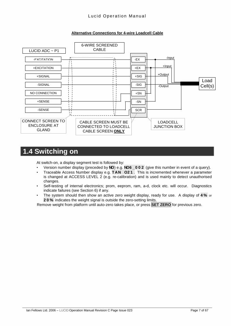
It is absolutely essential that the ‘sense’ inputs are connected. Normally, 6 wires are taken to the loadcell junction box where the ‘sense’ wires are linked to the ‘excitation’ terminals. In the unusual event of a direct loadcell connection (with only 4 wires), the ‘sense’ inputs must be linked directly to the ‘excitation’ terminals on the ADC module.
‘WAGO’ ADC P1 connector
Normal 6-wire Loadcell Cable Connection Schematic
Press Levers 1-7 Downwards
Insert Bared Wire -EXC
+EXC +Signal
-Signal
n/c
+Sense
-Sense
LOADCELL JUNCTION BOX
CONNECT SCREEN TO ENCLOSURE AT
GLAND
LUCID ADC ~ P1 6-WIRE SCREENED
CABLE
-EXCITATION
+EXCITATION
+SIGNAL
-SIGNAL
NO CONNECTION
+SENSE
-SENSE
CABLE SCREEN MUST BE CONNECTED TO LOADCELL
CABLE SCREEN ONLY
-Input
+Input
+Output
+Sense
Load Cell(s)
-EX
+EX
+SIG
-SIG
+SN
-SN
SCR
-Output
-Sense
L uc id Oper a t io n Ma nu a l
Ian Fellows Ltd. 2006 – LLUUCCIIDD Operation Manual Revision C Page Issue 023 Page 7 of 67
Alternative Connections for 4-wire Loadcell Cable
1.4 Switching on
At switch-on, a display segment test is followed by: • Version number display (preceded by NO) e.g. NO6_002 (give this number in event of a query). • Traceable Access Number display e.g. TAN O21. This is incremented whenever a parameter
is changed at ACCESS LEVEL 2 (e.g. re-calibration) and is used mainly to detect unauthorised changes.
• Self-testing of internal electronics; prom, eeprom, ram, a-d, clock etc. will occur. Diagnostics indicate failures (see Section 6) if any.
• The system should then show an active zero weight display, ready for use. A display of 4% or 20% indicates the weight signal is outside the zero-setting limits.
Remove weight from platform until auto-zero takes place, or press SET ZERO for previous zero.
LOADCELL JUNCTION BOX
CONNECT SCREEN TO ENCLOSURE AT
GLAND
LUCID ADC ~ P1 6-WIRE SCREENED
CABLE
-EXCITATION
+EXCITATION
+SIGNAL
-SIGNAL
NO CONNECTION
+SENSE
-SENSE
CABLE SCREEN MUST BE CONNECTED TO LOADCELL
CABLE SCREEN ONLY
-Input
+Input
+Output
-Output Load
Cell(s)
-EX
+EX
+SIG
-SIG
+SN
-SN
SCR
L uc id Oper a t io n Ma nu a l
Ian Fellows Ltd. 2006 – LLUUCCIIDD Operation Manual Revision C Page Issue 023 Page 8 of 67
2. CALIBRATION & ADJUSTMENT The calibration facility allows full re-calibration from the front panel, checking of calibration validity without disturbing existing parameters, or is a valuable diagnostic tool for initial set-up and subsequent fault-finding.
2.1 Initial Calibration On initial calibration, decide in advance what the calibration values are to be. Some systems will be supplied with the values already printed in the legend window to the left of the front panel weight display. If not, it is necessary to decide what the maximum (‘Max’) load of the scale is to be (typically determined by the associated ‘bottomworks’ (the mechanical part of the installation, including loadcell(s)). The maximum weight should not exceed the loadcell(s) capacity; remembering the extra effect of the ‘deadload’ (e.g. platform top or support structure on the active part); plus some margin should be left for ‘shock’ loading, dependent on the application. After deciding ‘Max’, the ‘scale interval’ (‘countby’ or ‘e’) must be selected. This must be a sub-multiple of 1, 2 or 5, anywhere between 0.001 and 50. For ‘trade’ applications, it must also be between 1/500th and 1/10,000th of ‘Max’; the actual value ultimately being a compromise between what can reliably pass Weights and Measures Initial Verification tests but not be so coarse as to be useless. The Actual Scale Interval ‘d’ is always the same as the Verification Scale Interval ‘e’, for the LUCID, and the ‘Min’, (below which it is illegal to trade) is usually 20e (20 x Scale Interval). E.G. Weigh platform with 4 x 200kg ‘shearbeam’ cells and support structure ‘deadload’ of 100kg. Wheeled stillages will be pushed off ramps so some shock loading is inevitable. Maximum combined capacity of loadcells is . 4 x 200kg = 800kg. Less ‘superstructure’ deadload . . . 800 - 100 = 700kg. Allow 20% overload capability for shocks 700 x 80% = 560kg. Set . . . . . . . ‘Max’ = 560kg. Theoretical range of Scale Interval is (560 / 10000) = 0.056kg and (560 / 500) = 1.12kg. A 1kg interval is clearly very coarse while the classification of the loadcells will limit the low value. 1/3000 is typical for the cells, so the high resolution limit is thus (560 / 3000) = 0.187kg. Therefore, a scale interval ‘e’ of 0.2 or 0.5kg would give resolutions of 1/2800th or 1/1120th. The ‘Min’ in each case would be (20 x 0.2) = 4kg or (20 x 0.5) = 10kg. If the ‘active’ range of the loadcell(s) is low (i.e. only using a small portion of the loadcells rated capacity for actual weighing), another limiting factor to ultimate resolution may be signal size. In trade installations there must be a minimum of 1 microvolt (1µV) change in loadcell signal for each division.
To check for adequate signal, substitute the selected scale interval in place of ‘CAL weight’ in the equation given below in section 2.8 ‘CAL’. If the ‘Millivolt reading’ is less than 0.001, a higher scale interval must be selected.
The usual unit of indication will be ‘kg’, but for some ‘heavy’ applications, such as weighbridges, it may be helpful to specify Tonnes as units (e.g. 100.00 x 0.02T ~ display of 100,000kg is unwieldy and uses the most significant digit which is sometimes also used for status indication).
L uc id Oper a t io n Ma nu a l
Ian Fellows Ltd. 2006 – LLUUCCIIDD Operation Manual Revision C Page Issue 023 Page 9 of 67
Follow the sequence (u indented steps are optional): • Press MODE for 1sec. goes to MAIN MENU (USER___), then £, £, £ to select calibn_. • Press MODE again to enter the calibration menu.
♦ Unless the SECURITY ACCESS LEVEL is already 2, the message pshbut or pass will be displayed.
♦ This is a request to press the internal CAL pushbutton, or key in the LEVEL 2 Password. ♦ If adjustment is not intended, press MODE to skip this step.
Calibrate Switch Access & Location
Note that updating any parameter of access level 2 or higher may invalidate the UNIT VERIFICATION. Until VERIFIED (or RE-VERIFIED) by a COMPETENT BODY the indicator will NOT BE LEGAL FOR TRADE. To obtain access to the switch the indicator case must be opened. Remove the 2 case securing screws and open the front panel. Non-trade units (cert 0) will ask for pASS instead of pshbut. The CAL button may still be pressed, else, a LEVEL 2 password may be entered (see 3.2 & 3.3).
[CAL] Switch Location
The following sequence will begin, although the £ or ¢ keys may be used to step to any wanted parameter: -
2.2 dISP ~ Display Countby and Decimal Point ( ‘e’ )
• Press MODE to show ‘countby’ (no. of divisions or the scale interval) together with decimal point position, if applicable. ♦ Press £ (or ¢) to step countby in sequence 1, 2, 5, 10, 20, 50, 1 ... etc. ♦ Press ¥ to step decimal point left (through max. 3 back to least significant digit)
• Press ENTER to set displayed selection and move on to ~
L uc id Oper a t io n Ma nu a l
Ian Fellows Ltd. 2006 – LLUUCCIIDD Operation Manual Revision C Page Issue 023 Page 10 of 67
2.3 toP ~ Maximum Display Capacity ( ‘max’ )
• Press MODE to show current value for MAX CAPACITY. ♦ Edit using the £, ¢ and ¥ keys as described in 3.5 below.
If in Trade Mode (cert 1), ‘max’ is restricted to a value ≤10,000e (divs, as above). Also if Trade, during cAL the loadcell signal must be ≥1µV for each division (e).
Note: The display will always be maintained for 9 divisions (countby) beyond this value. Having changed this value, full calibration MUST be carried out.
• Then press ENTER to set displayed selection and move on to ~
2.4 FILt ~ Filter Band Parameter See also section 2.11
• Shows current Filter Band Setting 00 - 08 or 10
♦ Press MODE to Edit using the £, ¢ and ¥ keys as described in 3.5 Set to '00' for the band to be automatically selected during calibration. Or choose a setting from 01 (light filter) to 08 (heavy filter).
A setting of 10 shows that the filter coefficient has been altered to a non-standard value using the FILTC parameter in the Config_ Menu.
• Press ENTER to set displayed selection or ¢ to step past and move on to ~
2.5 FASt ~ Fast Track Parameter See also section 2.11
• Modifies how the weighing filter is applied
♦ Press MODE to Edit using the £, and ¢ keys as described in 3.5.
1 = ON When in motion, filter is reduced to fast track large changes in weight. When stable, applies display freeze. Freeze releases after ~ 0.5 sec of motion. (Freeze can be disabled by setting ufrz = 1 in the Config_ menu)
Use for catch weight applications, e.g. parcel weighing.
0 = OFF Filter is uniformly applied. Freeze is disabled, display reacts immediately to weight change.
Use for dosing and filling especially where manual filling or adjustment needed.
Note: Batching mode automatically handles the way in which the filter applies during fill, FAST setting will affect the behaviour before and after fill.
♦ Then press ENTER to set displayed selection or ¢ to step past and move on to ~
2.6 dEAd ~ Deadload Offset Calibrate • Press MODE to show approximate millivolt output from loadcell(s). MSD will show flashing bars.
As excitation is approx. 10 Volts, the reading is ten times the mV/V loadcell output. • Note that, although the true output from the loadcell(s) will be affected by the use of any Intrinsic
Safety barriers, the ‘millivolt’ display will still read approximately 10 x the mV/V output in all cases. • Ensure weigh platform is empty and stable, and the mV reading is as might be expected.
L uc id Oper a t io n Ma nu a l
Ian Fellows Ltd. 2006 – LLUUCCIIDD Operation Manual Revision C Page Issue 023 Page 11 of 67
♦ Press ENTER to initiate automatic DEADLOAD acquisition. This will take several seconds. During each of the four stages of acquisition the MSD will show a rotating '0' with the LSD showing in succession 1, 2, 4 and 8. After completion, Zero Track and Set Zero are disabled until full calibration is completed.
♦ Alternatively, press ¢ to skip Deadload Calibration.
♦ Deadload may be re-acquired without the need to re-acquire the span - exit via TEST to store
the new value, for Verified Systems treat as re-calibration, unit will have to be re-verified.
• Display will eventually show ~
2.7 CALAt ~ Enter Span Calibration Weight • Press MODE to display currently defined Span Calibration Weight value. (For non-trade
applications see also 2.9 below "virtual calibration"). This may be any weight between 12.5% (6.25 % when non-trade) and 100% of the MAX CAPACITY (ToP). ♦ Edit in the normal way.
• Then press ENTER to ‘fix’ the displayed selection and move on to ~
2.8 CAL ~ Span Calibrate • Press MODE to show approximate millivolt output from loadcell(s). Note that this is active
output; i.e. the previously acquired deadload output is subtracted from the current output. Thus, 0mV is displayed if no calibration weight is loaded.
• Ensure weigh platform is loaded with the previously selected CALAT calibration weight value, it is stable, and the mV reading is as might be expected.
It is very important that the millivolt reading is close (within 10%) of the expected reading. A fault on the ‘SENSE’ signals from the loadcell may result in a millivolt reading 2~4 times higher than expected but give an otherwise, apparently ‘normal’ calibration. The result of setting up with a faulty ‘SENSE’ signal would be drifting and general instability of the weight reading. Millivolt reading = ‘CAL ’ weight x Loadcell Sensitivity x 10
Loadcell Capacity No. of loadcells in weigher
‘Capacity’ is the nominal rating as marked on the loadcell nameplate (in same units as ‘CAL’
weight). Always refer to Loadcell Manufacturers specifications/certificates. ‘Sensitivity’ is also marked on loadcell nameplate (typically 1, 2 or 3 mV/V). E.G. Single 20kg, 2mV/V loadcell used in platform with 8kg ‘CAL’ weight. Millivolt reading = 8 x 2 x 10 = 8mV.
20 1
(Sometimes a platform will incorporate multiple loadcells but be rated for a total (combined) capacity. In this case it is easier to use the total capacity figure and 1 loadcell in the equation.)
♦ Press ENTER to initiate automatic SPAN acquisition. This will take several seconds and
during calculation the MSD will show a rotating '0' for up to four stages. ♦ Alternatively, press ¢ to skip Span Calibration. (CAL may be skipped if it is only desired to
re-acquire DEADLOAD on a previously calibrated system. See also 2.6 above.) Display will eventually show ~
L uc id Oper a t io n Ma nu a l
Ian Fellows Ltd. 2006 – LLUUCCIIDD Operation Manual Revision C Page Issue 023 Page 12 of 67
2.9 tESt ~ Display Wt x10 (Fine Trim and Linearity) ♦ Pressing MODE puts into x10 weight display mode with a flashing T in the display MSD,
then~ ♦ ¥ = Enters a ‘SPAN TRIM’ mode (only if level 2), indicated by flashing T. in MSD (with decimal point.). ♦ £ = Nudges span calibration factor up by one tenth of a division. ♦ ¢ = Nudges span calibration factor down. ♦ Each ‘nudge’ moves the indicated weight, wherever nudging is done. Thus if scale is
calibrated and nudged at 33% of capacity then each nudge will represent a change of three tenths of a division at full scale.
♦ The limit of 12.5% of capacity applies so nudging is inhibited below this weight. • ENTER or MODE ends the span trim procedure OR you may go on to adjust linearity as
below.
N.B. Any adjustment to linearity; even just pressing £ or ¢ once; will permanently change the linearity parameters, even if the calibration procedure is subsequently aborted. No other calibration parameters are affected. (Keep records of LINS and LINB from ENGCFG_). Avoid using the linearity feature unless absolutely essential.
♦ ¥ = Enters a ‘LINEARITY TRIM’ MODE, indicated by flashing ‘L’ in MSD. ♦ Adjust the weight until the display shows required ‘breakpoint’ the weight at which the
correction will be applied (typically half ‘max’). ♦ £ or ¢ turns on the ‘TRIM’ MODE, indicated by flashing ‘L.’ (i.e. with d.p.). (Any previous linearity adjustment factor is cancelled at this point). ♦ £ = Nudges linearity calibration factor (LINS) up (max and zero are unaffected). ♦ ¢ = Nudges linearity calibration factor (LINS) down (max and zero unaffected). Each ‘nudge’ moves the indicated ‘breakpoint’ weight by 1/10th of a division (e). ♦ Press ENTER or MODE to end the procedure.
The EXIT route from the TEST display is shown in the following diagram. For normal calibration the operator would press ENTER twice to 'fix' the new data and show the menu heading CALIBN_, alternatively to discard new values and maintain the old ones the operator would press ENTER followed by ¥ twice, or any other key to return to the TEST display. Once back at the CALIBN_ menu heading, other menus may then be accessed, or the weight indication resumed by pressing ENTER, losing access level, or ¥ keeping the access level active for four minutes.
L uc id Oper a t io n Ma nu a l
Ian Fellows Ltd. 2006 – LLUUCCIIDD Operation Manual Revision C Page Issue 023 Page 13 of 67
Normal Menu Exit BUT [ENTER] loses PASS whilst [ ] will keep it active Notes - Using the above diagram
1/ To store new values when in Trade Mode, calibration MUST BE EXITED only from the TEST prompt display shown at the end of the calibration sequence. Exiting from other Menu Items will always abort. The thicker arrows/links show the usual route. 2/ In Non Trade Mode the sequence may be terminated from ANY MENU item, there is no requirement to start at the TEST prompt and the same exit route can be followed. 3/ Also in Non Trade only, if the power is switched OFF after a deadload acquisition and still in the CALIBN_ menu, then the new deadload value is remembered and calibration may be resumed when power is restored. Calibration may also be aborted and the old deadload values restored - even after a power failure. 4/ In either Mode, if calibration is exited properly, rather than just switching off the power, then the old calibration values are ALWAYS RESTORED if ABORT? is accepted; whilst new values are permanently stored (old ones lost) whenever SURE? Is accepted. ♦ Unless at ACCESS LEVEL 2, it is not possible to ‘fix’ any values obtained above. ♦ If in Trade mode, ¥ or ENTER (except in TEST) will abort calibration at any stage, restoring
previous values (with the exception of linearity parameters ~ see above). The display will show ABORT? and pressing either again will cleanly abort leaving the old values intact. Pressing any other key will return operation to the calibration function just exited.
♦ In non-trade mode - pressing the ENTER key will bring up the SURE? message and a second
press of ENTER will store the new values. Pressing ¥ instead of ENTER will bring up the ABORT? message. A further press of the ENTER key or the ¥ key will restore the old values.
tESt
ENTER or
Any Other Key
Any Other Key SurE?
ENTER
Abort? ENTER
or
New Cal Values stored
Old Cal Values restored
Menu Header CALIbn_
MODE Key Any Other Key
Span Trim+Lin
L uc id Oper a t io n Ma nu a l
Ian Fellows Ltd. 2006 – LLUUCCIIDD Operation Manual Revision C Page Issue 023 Page 14 of 67
♦ See Section 7.3 for details of recording established calibration values for future use if service is
required and calibration transfer has to be implemented. Note that due to the major differences between the 5000 and 6000 series, software calibration transfer between these different units will NOT BE POSSIBLE.
♦ After calibration the Display interval can be altered without the need for full re-calibration. DISP
located in the CALIBN_ menu can set a “pseudo” Display interval value - with the constraints that the decimal point cannot be moved.
2.10 SPAN ~ Virtual Calibration
Pressing ¢ when showing TEST in non trade mode enables Calibration via entry of the cell mV/V rating as an alternative to conventional calibration. Displays SPAN and the value can be entered in units of 0.001mV/V. If an accurate estimation of the active loadcell output in mV/V is available, this can be entered as a SPAN parameter. A deadload step (without a subsequent CAL step) must have been performed previously; an ERROR display or serial ‘?F’ error will be generated otherwise. The calculation is relatively straightforward. SPAN value = Loadcell rated output (mV/V) x System Max Capacity (TOP) No. of Loadcells x Individual Loadcell Rated Capacity Top Capacity and Loadcell Capacity must be in same units. If a single 2mV/V 100kg cell is used in the baseworks of a 60kg system, the active output of the cell (for maximum capacity) will be:
2 x 60 = 1.2 mV/V. Enter 1.200 to set the span.
100 Rather than using the loadcell manufacturers catalogue quoted nominal sensitivity, it is best to use the exact figures provided by the individual test certificate. In multiple cell applications, average the sensitivities of the cells. The limitations of this technique are: - • The indicator’s ADC internal gain varies slightly from device to device. An average millivolt
conversion factor (determined from factory production test figures) is pre-programmed into the indicator. A worst case error might be around a quarter of a percent of full scale.
• The loadcell manufacturer’s sensitivity figure may be wrong or may be affected by other cell
summing/cornering devices. • Because no proper test weighing takes place, obvious bottomworks problems such as binding are
not exposed ~ the full load may not be reaching the loadcell. An ERROR display means the sensitivity is too low. Performing a normal CAL test weighing forces the SPAN parameter to 0. It is not possible to read back a meaningful value if a conventional span calibration is performed.
L uc id Oper a t io n Ma nu a l
Ian Fellows Ltd. 2006 – LLUUCCIIDD Operation Manual Revision C Page Issue 023 Page 15 of 67
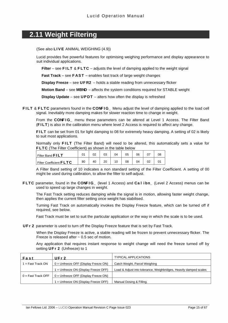
2.11 Weight Filtering
(See also LIVE ANIMAL WEIGHING (4.9)) Lucid provides five powerful features for optimising weighing performance and display appearance to suit individual applications.
Filter – see FILT & FLTC – adjusts the level of damping applied to the weight signal
Fast Track – see FAST – enables fast track of large weight changes
Display Freeze – see UFR2 – holds a stable reading from unnecessary flicker
Motion Band – see MBND – affects the system conditions required for STABLE weight
Display Update – see UPDT – alters how often the display is refreshed
FILT & FLTC parameters found in the CONFIG_ Menu adjust the level of damping applied to the load cell signal. Inevitably more damping makes for slower reaction time to change in weight.
From the CONFIG_ menu these parameters can be altered at Level 1 Access. The Filter Band (FILT) is also in the calibration menu where level 2 Access is required to affect any change.
FILT can be set from 01 for light damping to 08 for extremely heavy damping. A setting of 02 is likely to suit most applications.
Normally only FILT (The Filter Band) will need to be altered, this automatically sets a value for FLTC (The Filter Coefficient) as shown in the table below
Filter Band FILT 01 02 03 04 05 06 07 08
Filter Coefficient FLTC 80 40 20 10 08 04 02 01
A Filter Band setting of 10 indicates a non standard setting of the Filter Coefficient. A setting of 00 might be used during calibration, to allow the filter to self-adjust.
FLTC parameter, found in the CONFIG_ (level 1 Access) and Calibn_ (Level 2 Access) menus can be used to speed up large changes in weight.
The Fast Track setting reduces damping while the signal is in motion, allowing faster weight change, then applies the current filter setting once weight has stabilised.
Turning Fast Track on automatically invokes the Display Freeze feature, which can be turned off if required, see below.
Fast Track must be set to suit the particular application or the way in which the scale is to be used.
UFr2 parameter is used to turn off the Display Freeze feature that is set by Fast Track.
When the Display Freeze is active, a stable reading will be frozen to prevent unnecessary flicker. The Freeze is released after ~ 0.5 sec of motion.
Any application that requires instant response to weight change will need the freeze turned off by setting UFr2 (Unfreeze) to 1
Fast UFr2 TYPICAL APPLICATIONS
0 = Unfreeze OFF (Display Freeze ON) Catch Weight, Parcel Weighing 1 = Fast Track ON
1 = Unfreeze ON (Display Freeze OFF) Load & Adjust into tolerance, Weighbridges, Heavily damped scales
0 = Unfreeze OFF (Display Freeze ON) 0 = Fast Track OFF
Ian Fellows Ltd. 2006 – LLUUCCIIDD Operation Manual Revision C Page Issue 023 Page 16 of 67
Note: Lucid Filling mode (setd 01) automatically handles the way in which the filter is applied during fill. However Fast & UFr2 settings will affect the behaviour before and after fill. For example if weight might need manual top up after fill set Fast =0 (Off)
mbnd parameter, found in the config_ menu (level 2 Access) can be used to relax the conditions defining stability.
By default mbnd = 0 and can only be changed at Level 2 Access. This is designed to ensure that the weight signal is truly stable before operations such as Print or Tare are performed.
Less stringent conditions may suit some applications. Increasing mbnd (range 1-7) relaxes the conditions for stability such that dependent functions will act quicker though the weight might still be changing. Thus a Print could occur before the final weight is reached. A Legal for Trade application would use mbnd = 0.
updt parameter, found in the config_ menu (level 1 Access) sets the rate at which the display (and serial interface transmission) is refreshed. It does not otherwise affect the speed of operation (ie setpoints, printing etc.)
The display rate should be chosen for the application. Most platform and bench scales would use the default 03 whereas a weighbridge may suit a slower rate such as 06. Manual dosing applications benefit from faster rates (01). Very fast rates (00 & 02) demand a lot of processing time and should be avoided except for diagnostic purposes.
L uc id Oper a t io n Ma nu a l
Ian Fellows Ltd. 2006 – LLUUCCIIDD Operation Manual Revision C Page Issue 023 Page 17 of 67
3. KEYBOARD/DISPLAY The MODE pushbutton, if held pressed for 1 second, gives access to PARAMETER DISPLAY and
EDIT functions. ‘Parameters’ are the alterable settings that determine how this particular LUCID functions, what weight it displays, how it communicates with the outside world and what, or if, it prints. Some ‘day-to-day’ settings are accessible to the operator whilst other, more fundamental parameters are restricted to access by a supervisor or even the factory, by passwords and/or an internal ‘sealed’ pushbutton.
The MODE key operates differently if simply pressed, depending on the mode of operation.
• In Part Counting it will enable the 'Add nn' function.
• In Flow Rate first press will enable Net Wt display, the second press will enable Gross Wt display and the third press will return the display to normal flow rate mode.
• In Peak mode each press will cycle through Net Wt, Max., Min., and Gross. When showing Max the
MSD will have the top illuminated and the lower will be illuminated when displaying the Minimum.
By holding MODE for 1 second, the WEIGHT display is replaced by the first (USER___) of a list of Parameter Groups called the Main Menu. Each group consists of related parameters. The five front panel buttons now function according to the symbol in the top right: MODE, ENTER, ¥, £ and ¢. Their uses are shown below. • MAIN MENU MODE £ and ¢ step through the menu of GROUPS
OF PARAMETERS. (see 3.1) ENTER or ¥ return to WEIGHING MODE.
Having selected the required Parameter Group, pressing MODE steps to the first Parameter in that group’s list (via a password entry or pushbutton operation in some cases). This is ~
• PARAMETER DISPLAY MODE £ and ¢ step through the PARAMETERS. (see 3.2 and 3.4) ENTER returns to MAIN MENU MODE. ¥ returns to WEIGHING MODE.
Having selected the Parameter of interest, pressing MODE allows the display of any parameter value longer than 2 characters, and it’s alteration (editing), if permitted. Edit mode is indicated by a flashing character. This is ~
• PARAMETER EDIT MODE £, ¢ and ¥ modify the VALUE OF THE
PARAMETER. (see 3.5) ENTER ‘fixes’ new displayed value (if allowed),
and returns to PARAMETER DISPLAY MODE. MODE ‘remembers’ new value (doesn’t ‘fix’ it), and returns to PARAMETER DISPLAY MODE.
(To review original value, return to Parameter Display Mode, step to next Parameter, then back, then press MODE).
L uc id Oper a t io n Ma nu a l
Ian Fellows Ltd. 2006 – LLUUCCIIDD Operation Manual Revision C Page Issue 023 Page 18 of 67
Each key’s function is determined by the mode at the time, as shown below:
As a general rule: MODE moves one step to the RIGHT ENTER moves one step to the LEFT ¥ steps directly back to WEIGHING (fully LEFT)
The fold-out MENU DIAGRAMS at the rear of the document show the MAIN MENU Groups of Parameters as separate boxes with the MAIN MENU name at the top, along with it’s typical ‘protection’ ACCESS LEVEL. The PARAMETER NAMES are listed on the left of the box, in bold. Use these diagrams in conjunction with the following instructions.
3.1 Selecting a MAIN MENU
• From WEIGHING, press and hold the MODE key for about 1 second to enter the Parameter MAIN MENU mode.
• Step up or down through the MAIN MENU headings using the £ and ¢ buttons.
• These headings describe groups of parameters and have all character positions used with the last character always an underline ‘_’ e.g. USER___, help___, config_ etc.
GO TO ‘PARAMETER
DISPLAY MODE’
(VIA PUSHBUTTON + PASSWORD IF APPLICABLE)
EXIT TO ‘WEIGHING’
(ACCESS LEVEL ‘RESET’)
EXIT TO ‘MAIN MENU’
ACCEPT NEW PARAMETER
(IF VALID AND ALLOWED) & GOTO ‘PARAMETER DISPLAY
MODE’
FLIP TO ‘PARAMETER EDIT
MODE’
FLIP TO ‘PARAMETER DISPLAY
MODE’
(WITHOUT ACCEPTING NEW PARAMETER)
EXIT TO ‘WEIGHING’
(‘ACCESS LEVEL’ MAINTAINED
FOR 4 MINUTES)
EXIT TO ‘WEIGHING’
(‘ACCESS LEVEL’ MAINTAINED
FOR 4 MINUTES)
STEP DOWN TO NEXT
‘PARAMETER’
STEP UP TO PREVIOUS
PARAMETER
DECREMENT FLASHING DIGIT OF CURRENT PARAMETER VALUE
STEP UP TO PREVIOUS
‘MAIN MENU’ GROUP
STEP DOWN TO NEXT
‘MAIN MENU’ GROUP
INCREMENT FLASHING DIGIT OF CURRENT PARAMETER VALUE
MOVE TO NEXT LEFT DIGIT FOR EDIT
(PRESS AND HOLD FOR 2
SECONDS TO CLEAR DISPLAY TO ZERO’S)
MODE (+ hold)
PRINT
ENTER
SEMI AUTO TARE
SET ZERO
TEST
Weighing Mode
Main Menu Mode
Parameter Edit Mode
Parameter Display Mode
L uc id Oper a t io n Ma nu a l
Ian Fellows Ltd. 2006 – LLUUCCIIDD Operation Manual Revision C Page Issue 023 Page 19 of 67
‘Short’ and Full Menus (See Menu ‘Diagrams’ at rear of Manual)
To avoid confusion and simplify entry, the MAIN MENUS are divided into two groups consisting of a SHORT MENU of parameters likely to be modified during normal usage, and a FULL MENU, which includes more specialist system configuration parameters:
SHORT MENU FULL MENU
At ACCESS LEVEL 0 (normal condition), the SHORT MENU is automatically given. At LEVELS 1 or 2, the FULL MENU is given. To select higher ACCESS LEVELS, perform the following:
• Select totals_ to go through ACCESS 1 password entry procedure (3.2 & 3.3 below), or calibn_ to go to ACCESS 2 CAL switch operation (see section 2.1)
• On password entry completion, or CAL operation, the first parameter is displayed. Press ENTER to get back to the MAIN MENU then step to the required menu.
Either ENTER or ¥ keys may be used to return to WEIGHING mode. However, pressing ¥ will maintain the achieved ACCESS LEVEL for 4 minutes, during which re-entry to PARAMETER MODE is possible without having to re-enter the password or press CAL.
Calibration procedure
Batch and check-weighing setpoints
Totalisation
Tares, product code, printer ID etc, ‘flash’ look-up
Parts counting data
CALIbn_
COUNT__
USER__
BATCH__
TOTALS_
Printout formatting and text strings
Printer port characteristics
Factory set parameters
User accessible system set-up parameters
Serial comms port, multi-drop, remote display mode
DESCRIPTION
PR_FOR_
SERIAL_
CONFIG_
PR_CFG_
ENGCFG_
BUTTON_
IN_OUT_
Analog_
ENTRY
DESCRIPTION
Pushbutton disabling
Setpoint mode, control I/O, batch configuration modes
Analog output configuration and calibration
Analog enabled in EnGCFG_
At ACCESS LEVEL 0 (no password required) the full menu items are not available
Analog_ menu not available unless enabled
L uc id Oper a t io n Ma nu a l
Ian Fellows Ltd. 2006 – LLUUCCIIDD Operation Manual Revision C Page Issue 023 Page 20 of 67
3.2 Entry to PARAMETER DISPLAY MODE With the desired MAIN MENU group selected, pressing MODE will either show the first parameter or request operation of the internal CAL switch and/or entry of the password.
To Ignore Pushbutton and/or Password If a higher level is not required in order to alter a parameter, then the pshbut and/or pass requests are ‘stepped’ around by pressing the MODE key. (See CAL Switch and Password Entry section below for details of how to perform these operations.) The existing access level is shown, whilst the key is held pressed, as accessn (where 'n' will be 0, 1 or 2).
3.3 CAL Switch and Password Entry There are three available ACCESS LEVELS that allow alteration of parameters according to their degree of ‘protection’.
ACCESS ENTRY DISPLAY MODIFICATION LEVEL NAME METHOD ALLOWED? ALLOWED? 0 USER DEFAULT YES LEVEL 0 PARAMETERS Normal Level.
** Non-trade units may alternatively have password access to LEVEL 2.)
Internal CAL Pushbutton Operation • See Calibration Section 2 for details.
Password Entry • When attempting to access the following Menus, a request will be shown for either the pressing of
the Calibration Push Button, or the appropriate Password: - CALIBN_ TOTALS_ CONFIG_ or ENGCFG_
• Passwords are up to 4 digits long and are entered by selective use of the ¥, £, ¢, keys and the ENTER button.
NOTE: The Supervisor Password for new 'Lucids' is preset to ‘1’. It can be altered using the parameter SPAS found in the CONFIG_ menu. For Non-Trade Systems the default level 2 password is preset to 900 that can be found at CPAS in ENGCFG_. • Enter Main menu mode (press and hold the MODE key for 1 sec.) showing USER___, then
press the ¢ to step to Short Menu TOTALS_ and press MODE again to bring up the display PASS_, the (d.p.) ‘ . ’ indicates the least significant digit of the password to be entered. Press the £ button the correct number of times (the number of the digit). Default Supervisor Password is 1 so press the following sequence:-
£ ENTER
L uc id Oper a t io n Ma nu a l
Ian Fellows Ltd. 2006 – LLUUCCIIDD Operation Manual Revision C Page Issue 023 Page 21 of 67
• When the first digit is correct (it will NOT show) press the ¥ button to step to the next significant
digit and use the same procedure. In example the first digit is one. • The next digit (next least significant) is then keyed in the same way (not required in default),
followed by the third (again not required in example) and then the fourth digits (if applicable). On completion of all the required digits, the ENTER key should be pressed. When correctly keyed; accessn will be displayed as described above, where ‘n’ will be the achieved level number, 1 or 2. Access1 in example.
• e.g. to enter password “123” key in the following sequence: -
£, £, £, ¥, £, £, ¥, £, ENTER
• Whilst ENTER is held pressed, the ACCESS LEVEL achieved will be displayed (e.g.). On
release, the first parameter name in the group will be displayed. • Once an ACCESS LEVEL has been achieved it will remain effective so long as the operator does
not return to weighing. • On return to WEIGHING MODE using the ¥ key, the ACCESS LEVEL will remain effective for up
to 4 minutes in order to allow the effect of parameter changes to be investigated. (On re-entry to a MENU before this period expires, entry of PASSWORD and/or operation of the CALIBRATE PUSHBUTTON will not be required).
• Return to weighing by using the ENTER key cancels the ACCESS LEVEL immediately.
3.4 Parameter Display Mode • The parameters in a group are stepped through using the £ and ¢ keys. • The PARAMETER NAME is displayed, along with it’s one or two digit value. • If it’s VALUE is more than two digits long, EDIT mode must be selected to display it.
• ¥ directly exits the PARAMETER MODE back to normal weighing display. • ENTER exits the current parameter group and displays it’s MAIN MENU Heading. The MAIN MENU can then be stepped through as described above. • MODE changes to PARAMETER EDIT mode.
3.5 Parameter Edit Mode • The value is displayed with one digit FLASHING to show that it may be edited using the £ or ¢
keys. • If the £ or ¢ key is held depressed, an auto-increment mode begins after a short wait. • ¥ flashes the next left digit ready for editing (steps back to start when end reached). • If ¥ key is held depressed for 2 seconds, the displayed value is cleared to zeroes. • ENTER attempts to set the new value. The new value will be shown if accepted; alternatively, a NOPASS (incorrect ACCESS LEVEL) or other diagnostic message (see later) will be displayed.
• MODE reverts to PARAMETER DISPLAY MODE (the edited value is remembered). • One-digit parameters are reserved for those, which may only be ON (1) or OFF (0). When in
EDIT mode, £ or ¢ will ‘flip’ a 0 to a 1 or back.
L uc id Oper a t io n Ma nu a l
Ian Fellows Ltd. 2006 – LLUUCCIIDD Operation Manual Revision C Page Issue 023 Page 22 of 67
3.6 Permanent Parameter Storage Most updated parameters are written to a non-volatile parameter store (EEPROM) on pressing ENTER after editing (message: STORED will briefly appear). The calibration parameters are written ‘en bloc’ on successful completion of the CALIBRATION procedure. Once written, they are unaffected by loss of power. See above section 2.9.
3.7 Real Time Clock - Setting Time & Date LUCID contains a Real Time Clock - time and date can be set by adjusted by using the parameter Edit mode as detailed above. The clock/date is millennium compliant. Menu USER___ use £ to select parameter TINN format is HHMMSS – Use arrow keys to select the digits to change and to alter the display. Clock will start running on pressing ENTER. Use £ again to select DATE format is ddmmyy – adjust as needed, press ENTER.
3.8 Special PLU Parameters There are several cases where parameters are referenced or ‘looked- up’ against another parameter in the group. (See also PRESET TARE (4.2) and FLASHCARD (4.13) below.) In particular Product Codes are used in this manner. (PLU ~ Product Look Up)
Product Codes
Totalisation Registers, Printout Text Strings, Setpoints, and Parts Counting weights are maintained for each of 14 different PRODUCT CODES. Whenever one of these parameters is altered or updated, it only affects the value for the currently selected product. Whenever the CodE parameter is altered (in any Parameter Group), all of the above registers and parameters are changed to ones corresponding to the new Product. Details below: - MAIN MENU GROUP USER___ CODE, settable from 01-14, selects the current active PRODUCT CODE (defaults to
01). This forces the same CODE for all of the dependent parameters, as mentioned below; so totalisation, printing, setpoints, and part weights will all be correctly selected for the new active PRODUCT CODE.
TOTALS_ CODE, as above, which is set by the operator to 01-14 according to product in use.
All weighments will be subsequently totalised to that Products ‘file’, which can be printed (PTOT), or printed then cleared (CLRT), or merely displayed (GROS / NET / NO) by selecting the appropriate parameter from this menu. If CODE 99 is selected, printing, or printing and clearing can be simultaneously performed on all 14 products.
PR_FOR_ The first parameter is also CODE, which again can be set as required. The text ‘string’ describing the product is stored in four 7-letter locations named (ST1A / ST1B / ST2A / ST2B) which can be user programmed differently for each of the 14 PRODUCT CODES. Select the CODE required, before programming the 4 parameters above.
L uc id Oper a t io n Ma nu a l
Ian Fellows Ltd. 2006 – LLUUCCIIDD Operation Manual Revision C Page Issue 023 Page 23 of 67
Repeat the process for all required CODE numbers. When a printout is requested, the text string printed for DATA TYPE’s 2 and 3 (see Printer Formatting 5.6, DATA TYPE) is determined by the CODE selected at that time.
Select CODE 99 to programme the text ‘string’ printed whenever DATA TYPE’s B
and C are called for (this string is printed regardless of current CODE). BATCH__ Three setpoints (TARG / DRLB / SPT1). Note default SETD 07 renames these
SETP3 / SETP2 / SETP1), the in-flight compensation value (INFT), and the print tolerance band (PTOL) can be programmed independently for each of the 14 products. N.B. Setpoints 2 and 3 may appear as DRLB / TARG, TOL / TARG or LO3 / HIGH depending on the SETD value in the IN_OUT menu.
Count__ The part weight value (part) can be programmed differently for each of the 14
available CODE’s. Note that changing the currently active CODE in any of these Menus will automatically change the selected active Code in every other Menu.
Negative Number Entry Sometimes a parameter requires a negative value entry. To set the negative sign, step to the most significant digit (left most character). This digit only, steps through the numbers and then the '-' sign, allowing this to be set. N.B. Setpoints cannot be entered in negative format.
Hexa-decimal data ‘Hexa-decimal’ characters are simply an extension of the normal 0-9 numbering system giving 16 options, rather than 10 and go from 0 – through - 9, then A, B, C, D, E & F. Entry is as for normal numbers; the software automatically recognises when the selected parameter is in hex format and allows the £ key to step through all 16 ‘digits’. Hexa-decimal data is restricted in particular to Print Formatting, Leading spaces and trailing Carriage Returns, Cfrg and the ADC Configuration parameter found in the engcfg_ menu.
Alpha-numeric data entry Where a parameter requires an alpha-numeric entry the procedure is as above, except ~ • To make entry easier, text strings are entered from the left instead of from the right as with
numeric and hexa-decimal values. • If the ¥ key is held pressed for 2 secs, alpha strings clear to spaces instead of zeroes. • The increment/decrement £ or ¢ sequence is 0-9, A-Z using UP, or a-z going DOWN, ‘Esc’
(1Bh), ‘EOS’ code (1Fh), and ‘space’ code (20h).
L uc id Oper a t io n Ma nu a l
Ian Fellows Ltd. 2006 – LLUUCCIIDD Operation Manual Revision C Page Issue 023 Page 24 of 67
• Alpha characters are represented by a ‘stylised’ 7 segment character set (see note below). • Lower case characters are indicated by the presence of a steady ‘.’ (decimal point). To enter a
lower case ‘a’ use the up arrow 11 times (to step to ‘B’) then step back using the down arrow key to ‘A’. Approaching any letter from above makes it lower case, going up to a letter makes it upper case. Watch the d.p. turning ON and OFF.
• Non-printing control characters (special entry routine; see below) are displayed as ‘ ¯ ’ • The ‘EOS’ code (ascii 1Fh ~ looks like ‘ ’) is an optional ‘end-of-string’ terminator (any following
characters, including any in ‘Stxb’ if ‘EOS’ appears in ‘StxA’, will not be printed).
NOTE: The 7-segment display uses a stylised alphabet. Most letters are obvious but the following are cryptic:
cryptic: J = J, K = k, M = M, T = t, U = U and V, W = W, X = X
Printer control character entry
It is possible to include printer control characters in the ascii text strings. They are selected, either via the serial link or, by using this special entry mode from the front panel buttons ~ • Select the appropriate text string (‘StxA/b’ etc.) in the pr_for menu. • Select PARAMETER EDIT MODE. Any previously selected control characters will appear as ‘ ¯ ’. • Use the ¥ key to select the character to be edited. • Press both £ and ¢ keys at the same time. • The MOTION indicator will flash to indicate special entry mode and the character will appear in a
‘cryptic’ binary display format. • The special entry mode will remain on until the next character is selected. • The value of the control character is worked out as follows ~
Each segment has the ‘hexa-decimal value’ shown below, left. By adding the lit segment values, the control character value in hex is given. A table of ASCII codes will give values for each control character. An understanding of binary and hexadecimal notation is assumed in order to use this facility. The factory can give specific help, if required. (Avoid entering value 0Dh; this is ‘carriage return’).
L uc id Oper a t io n Ma nu a l
Ian Fellows Ltd. 2006 – LLUUCCIIDD Operation Manual Revision C Page Issue 023 Page 25 of 67
Display status indication The normal weighing units of measurement are legended on the front panel. In addition any
PARAMETER EDIT MODE display will always have a flashing character with NET/GROSS indicators extinguished to indicate a non ’live’-weight function.
Other displays functions are indicated by a flashing leftmost character where that character may be as follows ~
Flashing MSD F = Fail, Setd = 00 comparator mode H = High, Checkweigher mode. p = Pass, Checkweigher mode L = Low, Checkweigher mode
also, Linearity adjustment after test ; calibn_ E = Empty (Discharge), Batching mode d = Dribble, Batching mode b = Bulk, Batching mode t = Trim nudge phase at test step of calibn_ decimal point shows active. C = Count mode
m = loadcell mV output in DEAD and CAL calibration . = command pending ~ awaiting stable weight N = Peak max value u = Peak min value - = Negative Sign, this over-rides status byte.
In addition GROSS and NET indicators flash to
indicate displayed Totals, Preset Tares and ‘Flash’
weights.
(See 6 for table of Display Error Codes.)
Where two or more conditions apply, the
lower character in this table will have priority.
L uc id Oper a t io n Ma nu a l
Ian Fellows Ltd. 2006 – LLUUCCIIDD Operation Manual Revision C Page Issue 023 Page 26 of 67
4. ADVANCED WEIGHING FEATURES Having calibrated the LUCID, it immediately functions as a highly accurate weight indicator. However, the user or installer may need to customise the system by adjusting one or more of the sophisticated options available in software and described below. In addition, the Serial Interfacing and Printing chapter (see 5), describes how to set up and use the powerful communication and remote control features.
4.1 Net Weighing There are various methods of ‘tareing out’ existing GROSS weights in order to cancel container weights or for additive weighing. A ‘Semi-Automatic Tare’, which ‘cancels’ the current gross by pressing the appropriate front panel button, or one of 14 previously programmed (preset) tares may be selected. Preset tares may be selected ‘on top’ of an existing semi-auto tare, but a semi-auto tare cannot be selected once a preset is in operation. Pressing SEMI AUTO TARE while a preset tare is active will temporarily show GROSS weight. Pressing MODE steps between NET (if a tare is active) and GROSS displays. The displayed weight mode is always indicated by the NET and GROSS leds. Any failure to remain in NET mode could be due to a hardwired (control input) ‘cancel tare’. The SEMI AUTO TARE button will tare out any existing positive, stable weight; the NET indicator illuminates to indicate tare in operation. There is no limit to how many times the SEMI AUTO TARE may be used, so additive weighing is permitted. Pressing and holding the SEMI AUTO TARE key, for 1 second, clears any existing semi-auto tare and returns the display to GROSS mode.
4.2 Preset Tares (tArE in USEr___) There are 14 preset tare weight ‘registers’ (tArE 01-14) that can be pre-programmed by the user. • In the USER___ MAIN MENU, select tArE ~ the currently selected ‘register address’ is
shown. • Press MODE to enter EDIT mode and select a preset tare ‘register address’ between 01 and 14. • Press MODE to show the existing weight value in the selected ‘register’ (NET and GROSS
flashing). (You may step to other preset tare ‘registers’ using the £ and ¢ keys whilst in this mode - while the key is depressed, the next ‘register address’ is displayed - when released, it’s contents are shown.)
• Press MODE to enter TARE EDIT mode for weight value (least significant digit flashing).
• Either - press ENTER to revert to ‘register address’ display, accepting the current value, • Or - alter the value as in normal EDIT mode, then press ENTER.
• Return to weighing, ENTER or ¥, or step to next location by re-entering EDIT mode. Note: ‘TARE 00’ is the default and is always zero; forcing a GROSS weight display if selected.
L uc id Oper a t io n Ma nu a l
Ian Fellows Ltd. 2006 – LLUUCCIIDD Operation Manual Revision C Page Issue 023 Page 27 of 67
• Press MODE (hold), MODE, MODE to show current address (in flashing EDIT mode). • Change ‘tArE’ no. to required one by using £, ¢, ¥ and ENTER (or MODE). • The preset tare weight in the selected address will be displayed with NET and GROSS flashing. • Press ENTER to select it. Then ENTER, ENTER to return to weighing.
• Press MODE (hold), MODE, MODE, MODE to show tare weight in current address. • Press £ or ¢ keys to step through all preset ‘tArE’ ‘addresses’ until the correct one is found. (While the key is depressed, the ‘tArE’ address about to be ‘opened’ is displayed.) • Press ENTER to select it. Then ENTER, ENTER to return to weighing.
Entering a New Tare Value into a Preset Tare ‘Register’
• Press MODE (hold), MODE, MODE to show current address (in flashing EDIT mode). • Change ‘tArE’ no. to a ‘spare’ one by using £, ¢, ¥ and ENTER (or MODE). • The preset tare weight in the selected ‘tArE’ no. will be displayed with NET and GROSS
flashing. • Press MODE then edit it. The digit to alter will be flashing. • Change weight to required value by using £, ¢, ¥ and ENTER when correct. • Then ENTER, ENTER to return to weighing.
300 300kg edited to 200kg Enter
Mode
Enter
Enter
Mode
Mode
Fixes value
Enter
Not beyond TARE 01
Mode
300 R R
↑
↑
500 R R
Tare 04
500kg tare stored in tare 04
New ‘register address’ displayed while pressed
– not beyond Tare 14
↓
150 R R
600 R R
↓
Tare 03
Select tare ‘register address’
Edit
User
Mode
Enter Mode
Tare 03
Code
↑↓
↑↓
Tare 13
NET and GROSS flashing
Tare 02 Edit
200
Underscored digit flashes
Parameter Mode
Parameter Edit Mode
Preset Tare Step Mode
Preset Tare Edit Mode
L uc id Oper a t io n Ma nu a l
Ian Fellows Ltd. 2006 – LLUUCCIIDD Operation Manual Revision C Page Issue 023 Page 28 of 67
General Notes
• ‘tArE 00’ is always zero, so forces GROSS weighing when selected. • DISPLAY GROSS WEIGHT Press SEMI AUTO TARE. GROSS is displayed only while key is pressed. • DISPLAY PRESET TARE Press MODE (hold), MODE, MODE, MODE Press ¥ to revert to NET display. • TURN PRESET TARE OFF Press MODE (hold), MODE, MODE, hold ¥ for 2sec
Press MODE (or ENTER), to revert to NET. This selects ‘TARE 00’ which disables the Preset Tare.
• ZERO SELECTED TARE Press MODE (hold), MODE, MODE, ENTER, MODE, ¥ and hold depressed for 2 seconds. Press MODE (or ENTER), ¥ to revert to NET.
Automatic Tare Cancellation
A feature that allows automatic cancellation of any tare may be selected by setting ZSEt1 in the ConFIg_ menu. Having initiated a semi-auto and/or preset tare, once the net weight has stabilised at any positive value, then subsequently re-stabilised for 5 seconds with a negative value within the zero-setting range (i.e. typically within -2% of original gross zero), the tare(s) is cancelled and a SET ZERO is performed.
L uc id Oper a t io n Ma nu a l
Ian Fellows Ltd. 2006 – LLUUCCIIDD Operation Manual Revision C Page Issue 023 Page 29 of 67
4.3 Checkweighing (Catchweighing) Several checkweighing modes are available as described below. The mode is set by the parameter entered against SEtd in the In_Out_ MENU. With the default Setd07 the tolerance bands are defined by SPt1, spt2, and setp3 in the bAtCH__ MENU. These three parameters, that may have different names for various SEtd values, can be set individually for each of the 14 PRODUCT CODES. Typical wiring diagrams which enable full decoding of output relay states are shown below.
• Select CodE parameter and select Material PRODUCT CODE (01 - 14) • Select spt3 (Setpoint 3) and enter, usually, the Target Weight • Select spt2 (Setpoint 2) and enter the Dribble/Tolerance (but see variations below) • Select SPt1 (Setpoint 1) and enter ‘lower enable limit’ (see below) • Select PtoL (Print Tolerance) and enter limits for printing, if required (see 4.5 Printing in
Batch, Setd 01 & 07 only)
In the tables below, the defaults are for zero to be the Net Zero (i.e. with any selected tare included); the setpoints are positive with respect to zero; and the comparisons occur instantaneously. It is possible to modify these defaults by altering the Output Allocation parameter ‘oPAL’ (see 4.7).
4.4 Setpoint Operation There are several selectable Setpoint Modes in order to cater for a wide variety of applications. Most require some external connection. The ‘control’ outputs and inputs are described below.
Outputs 1 and 2
Several output options are available and can be identified by examining the actual relays on the ‘baseboard’ next to the I/O connector (RL1, RL2). • Metal cased HE221C…~ 175V, 0.25A, 5VA
The LEDs ‘OUTPUT 1 and 2’ (D8 and D9 ~ see 5.1) light when the corresponding relay operates.
OUTPUT 1(2) N/C
OUTPUT 1(2) N/O
OUTPUT 1(2) COM
L uc id Oper a t io n Ma nu a l
Ian Fellows Ltd. 2006 – LLUUCCIIDD Operation Manual Revision C Page Issue 023 Page 30 of 67
Control Inputs 1 and 2
220R (snipped for normal operation)
The normal method for connecting to the control inputs is from an external 12-24V AC or DC power source, via the controlling contact or transistor. R17/19 must be snipped. The switching current is 10-20mA. The contact or transistor may be in series with either input and the supply polarity is not important unless a transistor is used as the switching element.
If it is desired to use a ‘passive’ volt free contact, the scheme shown ‘dotted’ may be used, but is not recommended. The contact must reliably switch 5V at 10mA (i.e. good quality gold plated signal relay), and be wired with a maximum length of 10m of screened 2-core cable; screen grounded only at enclosure on entry. In this case, R17/19 must be fitted.
Optional Third O/P (Special build)
A factory fitted option is to replace CONTROL INPUT 2 with a third O/P. This is a limited current (20mA max.), opto-transistor output which operates according to it’s ‘oPAL’ ‘Output 3’ definition. Maximum ‘off’ voltage is 30V (any external power supply voltage); ‘on’ voltage drop <1V @ 20mA. For assignment parameter, see section 4.7.
INPUT 1(2)A
INPUT 1(2)B
Transistor alternative to
contact
Alternative for volt-free contact (5v 10mA gold)
R19(17) fitted
GND
CASE
LUCID INPUT
DETECTION AND
ISOLATION CIRCUIT
R 19 or 17
1K
220R
External 12-24V Supply
Isol. 0V
Isol. 5V
LOAD >1.2k/600Ω + EXT. PSU 24V/12V
-
LOAD >1kΩ (max o/p 5V)
CONTROL 2A
CONTROL 2B
R 17
10R
10R
isol.+5V
GND Isol. 0V
Use commutation diode with inductive load e.g. relay
Alternative Interface (R17 fitted)
Preferred Interface (‘snip’ R17)
220R
L uc id Oper a t io n Ma nu a l
Ian Fellows Ltd. 2006 – LLUUCCIIDD Operation Manual Revision C Page Issue 023 Page 31 of 67
Setpoint Mode Descriptions The tables below define the operation of the outputs (Op1, 2), the serial comms (Status) letter, the displayed (Indicator) status letter and describe the condition for actual Weight compared with each setpoint (SPt1, 2, 3). The setpoint mode parameter is SEtd in the In_oUt_ menu at access level 1.
SEtd 00 -- Comparator setpoint mode Pass/Fail--- Weight Op1 Op2 Status Indicator on off ‘F’ ‘F’ail Out of Tolerance/ Fail high----- off on ‘P’ ‘P’ass In Tolerance/ Pass low----- on off ‘F’ ‘F’ail Out of Tolerance/ Fail SPT1----- off off 'Z’ ‘ ’ Near Zero Zero------------ Tolerance (tolp), pass condition determined by spt2 – spt3 and if weight positive.
SEtd 01 --- See Batch Weighing
SEtd 02 -- Encoded comparator mode Lo/Pass/Hi--- (Default) Weight Op1 Op2 Status Indicator on on ‘H’ ‘H’igh Out of Tolerance/ Fail high----- off on ‘P’ ‘P’ass In Tolerance/ Pass low----- on off ‘L’ ‘L’ow Out of Tolerance/ Fail SPT1----- off off 'Z’ ‘ ’ Near Zero Zero------------- Tolerance (tolp), pass condition determined by spt2 – spt3 and if weight positive.
SEtd 03 --- Direct Control via serial interface (for test purposes only)
SEtd 04 -- Encoded comparator tolerance Lo/Pass/Hi--- tol is a tolerance, entered as a weight value - previously SPt2
Weight Op1 Op2 Status Indicator on on ‘H’ ‘H’igh Out of Tolerance/ Fail Targ + Tol-- off on ‘P’ ‘P’ass In tolerance/ Pass Targ - Tol-- on off ‘L’ ‘L’ow Out of Tolerance/ Fail spt1 1----- off off 'Z’ ‘ ’ Near Zero Zero------------- Tolerance (tolp), pass condition only if tolerance is > target.
L uc id Oper a t io n Ma nu a l
Ian Fellows Ltd. 2006 – LLUUCCIIDD Operation Manual Revision C Page Issue 023 Page 32 of 67
SEtd 05 -- Encoded comparator % tolerance Lo/Pass/Hi--- S2 entered as % of S3; > 99 interpreted as 100% - previously SPt2 and SPt3 Weight Op1 Op2 Status Indicator on on ‘H’ ‘H’igh Out of Tolerance/ Fail Targ + Tol% of Targ----- off on ‘P’ ‘P’ass In tolerance/ Pass Targ - Tol% of Targ----- on off ‘L’ ‘L’ow Out of Tolerance/ Fail spt1------------------------- off off 'Z’ ‘ ’ Near Zero Zero--------------------------------- Tolerance (tolp), pass condition only if tolerance is > target.
SEtd 06 - As SEtd 05 but with Analogue Display Mode - As MODE 5 but with weight display segments used as an ‘analogue’ Filling guide. → S3+S2% ↑ ← S3-S2% S1 → ↑ Between zero weight and Setpoint 1 (Status ‘?’), the display is blank. Between Setpoint 1 and the lower ‘PASS’ limit (S3-S2%) (Status ‘L’), the bottom row of 7 horizontal segments and the lower right hand vertical segment progressively illuminate from the left as weight increases (so if the left 4 segments are lit, the weight is half way between S1 and S3-S2%). Within the ‘PASS’ range (Status ‘P’), S3-S2% to S3+S2%, the 7 centre horizontal segments gradually illuminate from right to left with increasing weight (so 4 centre segments lit represents exact target). The whole display flashes whilst the weight is in the ‘PASS’ region. Above the upper ‘PASS’ limit (Status ‘H’), the upper left most vertical segment and the top 7 horizontal segments progressively illuminate towards the right as the weight increases to scale ‘max’. Weight Op1 Op2 Status Display on on ‘H’ High S3+S2% ↑ ←S3-S2% S1 → ↑ Targ+Tol % of SPT3------------- off on ‘P’ Pass S3+S2% ↑ ←S3-S2% S1 → ↑ (flashing) Targ-Tol% of SPT3-------------- on off ‘L’ Low S3+S2% ↑ ←S3-S2% S1 → ↑ SPt1---------------------- off off 'Z’ Near Zero (off) Zero---------------------- Tolerance (tolp), pass condition only if tolerance is > target. Pressing [TEST] forces display to digital weight reading mode, temporarily (if in trade mode).
SEtd 07 -- Simple 3 trip mode --- (Control Input2 requires isolated output configuration (see above) to provide uncommitted darlington output, may be decoded with relays)--- Weight Op1 Op2 (CI2) (SPt3 < Wt) on on on SPt3-------- (SPt2 < Wt) on on off i.e Each Output independently relates SPt2-------- to its own Set Point and the shown (SPt1 < Wt) on off off conditions will apply if Spt3>Spt2>Spt1 SPt1-------- (Wt ≤ SPt1) off off off Zero--------
L uc id Oper a t io n Ma nu a l
Ian Fellows Ltd. 2006 – LLUUCCIIDD Operation Manual Revision C Page Issue 023 Page 33 of 67
Comparator wiring suggestions To fully utilise all states on the two output relays, the following suggested circuits use external relays. Fig 1. Setpoint mode 00 Fig 2. Setpoint modes 02, 04, 05, 06
4.5 Batchweighing It is advisable that a good knowledge of the Control Input IPAL and Control Output OPAL commands as described in sections 4.6. & 4.7 of this manual is understood before Lucid is configured for batching operations.
In_oUt SETD 01 ~ Batching Control
SEtd 01 is selected in the In_oUt_ MENU. Setpoints are defined in the bAtCH_ MENU as is the InFt and the PtoL Print Tolerance parameter which determines the acceptable limits for printing about the target. These five parameters are set individually for each of the 14 PRODUCT CODES. Before the batchweighing functions are used, certain parameters may need to be preset according to how the user wishes his system to operate.
Figs 1. and 2. only applicable to DC. It is recommended to fit suppression devices across external relay coil (e.g. varistor type V47ZA1 for 24v or lower voltage relays).
Fig 3. When changeover relays are installed, 4 devices (e.g. lamps, LEDs or relays) may be connected to indicate all 4 possible status’s.
OP1 OP2
OP1
OP2
IN RANGE FAIL PASS
PASS
LOW
HIGH
HIGH/1
HIGH/2
+
OP 1 (off)
OP2 (off)
PASS / DRIBBLE
HIGH / BULK
LOW / DISCH
NEAR ZERO
+
L uc id Oper a t io n Ma nu a l
Ian Fellows Ltd. 2006 – LLUUCCIIDD Operation Manual Revision C Page Issue 023 Page 34 of 67
Start and Stop Command Remote Start and Stop functions can be configured by setting IPAL - Typicaly set to ‘01’-see 4.6
Control Options for Batching
Printing in Batching
The details given below outline the key parameters that govern printing during batching operations. bAtCH_ PtoL Determines pass/fail criteria for batching. Sets the limits for
Autoprinting in conjunction with toLP and poSt. Can be set for up to 14 batch product codes.
Samp Enables some weighments to be immediately discharged on cut-off
without tolerance checks, printing or auto inflight compensation. The samp number, 1 to 99, is the interval after which a check is initiated. Values of 00 & 01 mean checks are made for all weighments.
Pr_CFg_ ToLP Print In Tolerance parameter may either be ON (1) or OFF (0). If OFF
tolerance checking will not be done, even if PtoL is active, if ON then operation depends on the Setpoint Mode selected. If Setd 01 or 07 then tolerance check will be +/- the PtoL value of the tArg (Setpoint 3) i.e the 'Ready to Print' flag will be set when in these bounds (Printing will occur when other conditions all correct).
If Setd 00, 02, 04, 05 or 06 then the 'Ready to Print' flag will be set when the weight is within the "PASS" Band as set by the three setpoints and this will over-ride any ptoL value that may be set.
PoSt Print in Positive Tolerance parameter may also either be ON (1) or OFF(0)
and enables positive only tolerance checking. If OFF then tolerance checking will be exactly as defined in toLP. If ON then the tolerance check will be + PtoL of targ . This restricts the scope of PtoL such that the 'Ready to Print' flag will only be set when within the positive tolerance. Note that tolp must be ON for this to be effective.
NOTE THE ‘STOP’ INPUT IS
CONFIGURED TO BE ‘FAILSAFE’; IT MUST BE PRESENT BEFORE THE ‘START’ SIGNAL WILL BE
RECOGNISED. THE ‘STOP’ INPUT MUST NOT BE USED AS AN
‘EMERGENCY STOP’. IP2
IP1
Stop
Run (auto restart on discharge)
START INPUT
STOP INPUT
IP2
IP1
Break to abort
Momentary action to Start
START INPUT
STOP INPUT
L uc id Oper a t io n Ma nu a l
Ian Fellows Ltd. 2006 – LLUUCCIIDD Operation Manual Revision C Page Issue 023 Page 35 of 67
Auto 0 Autoprint disabled, print must be manually requested. Auto 1 Autoprint enabled, a printout will occur as soon as conditions for
printing are met (see below and 5.5). With default settings, this would mean a print occurring at the first stable weight above ‘Min’ but prohibited in SM01 until Batch programme is run.
In_oUt_ oPAL 000000 Used to redefine the O/P function see Section 4.7.
Discharge and Print Parameters In_oUt_
DSCH The Bulk Output can be allocated as a Discharge Output. The Discharge mode parameter can be used to force the discharge at the end of the 'batching' program regardless of achieved weight. May either be ON (1) or OFF (0). If OFF, the default setting, then at the end of the 'batching' program the MSD will display an E indicating the end. No discharge will occur. If ON then at the end of the program, Output 1 (Bulk O/P) will turn ON again indicating a discharge is required. This Output will remain On until the weight drops below the value entered to setpoint one.
DSPr Discharge on Print parameter can be used to inhibit the discharge if a
successful print has not occured. May either be ON (1) or OFF (0) and if OFF, the default value, then discharge will be dependent solely on the state of dSCH as above. If ON then discharge will only occur after a successful print function has completed. If not automatic, or out of tolerance, then manual adjustments can be made prior to printing and then discharging. Note that dsch must be ON for this parameter to be effective.
Calm Timer and Jogging. In_oUt_ CALm The Batch Calm Timer may be set to run at the end of a batch to allow filling
to complete. Can be set from 00 (default) to 99 and determines the length of time the system waits in 0.1 second increments. I.e. 40 = 4 seconds and this will be the interval after the dribble output has turned OFF before the weight will be checked and the batch "program" can proceed. Also sets the interval (plus motion criteria) between jogs, see next.
Jogt Determines whether jogging is active (01 to 99) or turned OFF (00 the default
value). If the batch weight achieved is below the minimum tolerance set by ptol/tolp/post, and jogging is active, then up to three jogs may occur to bring the weight within required limits. The value entered will be used to determine the JOG ON interval in milliseconds. The value entered will round down to the next 20mS i.e. any entry of 1-19 will go to 0mS; an entry of 21-39 will give a jog ON period of 20mS.
L uc id Oper a t io n Ma nu a l
Ian Fellows Ltd. 2006 – LLUUCCIIDD Operation Manual Revision C Page Issue 023 Page 36 of 67
Batching Parameters • CodE parameter and select Material PRODUCT CODE (01 - 14). Each of the following
parameters can be set to suit Material code selected. • ofil Overfill offset for cut off and inflight calculations – (range 0-255e) • tArg (Setpoint 3) desired Final TARGET Weight. • drIb (Setpoint 2) the DRIBBLE (fine) FEED Quantity. • SPt1 (Setpoint 1) Display must be within this limit to permit Start i/p • InFt (In-flight Compensation) the estimated ‘IN-FLIGHT’ WEIGHT VALUE, + or -. • PtoL (Print Tolerance) limits for printing • Jogt (Jog Time) On Period for Jog mS
• SamP (Sample final achieved weight every nn) Skip checks at batch end. • Atst 1 Autotare on start (~ in In_oUt_ ) if required. • AinF 1 Automatic In-Flight-Compensation’ (~ in In_oUt_ ) if required. • Ensure the Control Inputs are correctly selected for START/STOP commands if used.
Start the batch either remotely or locally as described below. • It is preferable to disable the analogue output when batchweighing in order to achieve
best ‘cutoff’ accuracy in high-speed applications (AnEn 0 in Eng_CFg). Default is disabled.
Typical Batching Cycle
START SIGNAL (Note: stop input is ‘failsafe’, hence must be energised). • Provided that the displayed weight is stable, Motion Lamp is OFF, and the displayed weight
is below the value entered to the parameter spt1 then: - • Either, Signal to ip1; which must be selected for “Start” - IPAL0x • AUTO-TARE TO NET ZERO adjustment will occur if Atst1 • or, Set Strt1 in bAtCH__ menu, • or send ‘ST1’ command from serial port. • In above two cases ; Feed starts immediately if weight is less than the high limit
Note: Start will continue to attempt to activate as long as the start signal is active, i.e. would wait for a stable condition and then start. Signal should be removed once a valid start has occurred.
Start Command
OP1 ‘ON’
OP2 ‘ON’
‘Dribble’ ‘Bulk’ SPt 1
Stable
‘Discharge’
‘calm’ time and waiting stability
OP1 ‘ON’ (if selected)
Time
tArg + oFIL – InFt - DrbL
tArg + oFIL – InFt)
(tArg + Ofil) (Target)
Weight Print
If non-sampled OR Calm AND Jog AND Autoprint
NOT selected, go straight to ‘Discharge’
If ‘Auto Tare on Start’ enabled and I/P 1 (start) is on,
will start looking for stability here
L uc id Oper a t io n Ma nu a l
Ian Fellows Ltd. 2006 – LLUUCCIIDD Operation Manual Revision C Page Issue 023 Page 37 of 67
• BULK FEED Output 1 (Bulk) and Output 2 (Dribble) OPERATE b on MSD display • Output remains on until the the weight exceeds the
At this point Output 1 releases, leaving Output 2 to complete dribble feed. O/P 1 is NOT latched and would turn ON again if the weight dropped back below this Cut-Off Value.
• DRIBBLE FEED - Output 2 Remains operated d on MSD display
• Output 2 remains on until final cut-off point~ • FINAL CUT-OFF = TARGET - INFLIGHT .
At this point Output 2 Releases. O/P's 1 & 2 now latch OFF pending any further conditions.
• CUT-OFF - occurs (display MSD blank)
If a Non-Sampled weighment go to Batch Complete below. If CALm timeout is awaited bUSY displays.
• If Automatic In-flight Compensation Adjustment is selected AInF 1 and a stable weight within +/-12.5% of the capacity is detected, an adjustment of the currently selected InFt value by 25% of any error is carried out subject to total restrictions.
• If jogt is active and final weight is below the minimum tolerance set then the system may jog the product three times to try to achieve an in-tolerance weight. The System will turn ON the Dribble Feed Output 2 for a period as set to this parameter and then OFF for the period entered in CALm plus the period required for weight stabilisation and weight check.
• If AUTOPRINT mode is NOT selected (Auto 0 in Pr_CFg_), the cycle stops until the operator removes/discharges the batch. A printout may be obtained prior to discharge by pressing PRINT or requesting ‘PR’ via the Serial Interface (E on display msd)
• If AUTOPRINT mode IS selected,
If stable weight is within tolerance an auto-print of the selected data will occur.
• BATCH COMPLETE E on display. Subject to Discharge conditions, Output 1 OPERATES to denote DISCHARGE. This special discharge state may be used to initiate DISCHARGE, or operator controls load removal directly. Batch Complete status (see 4.7) could be allocated to O/ps 1 or 2, if single feed, or O/p 3 if available. • If START COMMAND from remote Input 1 is still valid, the next cycle starts as soon
as weight stabilises below Setpoint 1. Otherwise, a new Start Command is awaited before re-commencing the cycle.
Note: - SEMI AUTO TARE and PRINT are disabled during fill.
4.6 Remote Operation (Control I/P assignment) The two Control Inputs can be configured to act as Start/Stop Batch signals or as remote alternatives for the front panel buttons (see 4.3 for typical wiring). The IPAL parameter in In_oUt_ is a two-digit parameter; the first selects input 1 action; the second (least significant) selects input 2 action.
L uc id Oper a t io n Ma nu a l
Ian Fellows Ltd. 2006 – LLUUCCIIDD Operation Manual Revision C Page Issue 023 Page 38 of 67
‘IPAL . <i/p1> . . . . <i/p2>’ 0 = start batch 0 = start batch 1 = hold batch (after fill) 1 = stop batch 2 = acquire tare (default) 2 = acquire tare 3 = toggle tare (acquire if in Gross, 3 = cancel tare (default) 4 = print cancel if in Net) 4 = print 5 = set zero 5 = set zero 6 = display gross 6 = display gross 7 = send/display totalised net wt.+ 7 = send/display totalised net wt.+ 8 = print/clear totalised wt.+ 8 = print/clear totalised wt.+ 9 = print, don’t clear, totalised wt.+ 9 = re-configure i/p2 as output 3* + operate on currently selected PRODUCT CODE total. 8/9 clear/print all if CODE = 99. * requires i/p2 to be factory (hardware) configured as an output.
Note - A second indicator may be used as a ‘Remote’ Display/Keyboard for the ‘Local’ indicator. See Section 5.7 for more information.
4.7 Control O/P and Printout Assignment The oPAL parameter in In_oUt_ consists of six hex digits, which can modify the operation of each output as below ~
Digit No: 1 2 3 4 5 6 7
OUTPUT 1 OUTPUT 2 OUTPUT 3 (only if fitted)
Not Used – see note
Comparator Mode
OUTPUT 1 Comparator Mode*
Status Mode
Comparator Mode*
Status Mode
Note: Digit 1 is unused – from NO6_00F is automatically set by the software and used as a check digit. * These digits unused except in Setpoint Mode SEtd 07.
Outputs operate as described in Setpoint Mode descriptions (see 4.3 and 4.4), but may be customised using these digits. Leave as all zeroes unless special function required. In such cases, read the following carefully before modifying Digits 2-7.
Digit 2 Modifies how outputs operate in Setpoint Modes other than ‘07’ 0 (Default) Setpoint weight value based on Net Weight. Setpoint values are positive of
this zero, and output operation is ‘instantaneous’ (stability is not awaited). 1 Setpoint weight values based on Gross Weight (‘zero’ is always true zero weight).
Only valid for Setpoint Modes 00, 02, 03 and 07. 2 Setpoints operate when Negative of indicated zero instead of positive (for weighing
out). 4 Setpoints operate when Positive or Negative (i.e. on the modulus of weight). 8 Must await stability (no-motion) before outputs operate.
The values above may be summed to give a combination of ‘modifications’. E.G. 'OPAL 9xxxxx’ (i.e. 8+1) would delay output operation until a stable gross weight at or above the particular setpoint was reached. ‘OPAL Cxxxxx’ (8+4); output operates when no motion at or beyond setpoint, positive or negative of NET zero.
L uc id Oper a t io n Ma nu a l
Ian Fellows Ltd. 2006 – LLUUCCIIDD Operation Manual Revision C Page Issue 023 Page 39 of 67
Digits 2, 4, 6 Modify how outputs operate in Setpoint Mode ‘07’ In this mode, each output has it’s own ‘definition’ digit, each as described above, rather than all being forced to the same function as defined by digit 2. Thus, one output might be modified to operate only on no-motion, for example.
• Output 3, if fitted (factory option), is only available for Setpoint Mode in Mode 07. In other modes
it may therefore be used to indicate a particular Status condition; according to the table below.
Digits 3, 5, 7 If not at zero (default), the Output (1, 2, 3) corresponding to the digit (3, 5, 7) is forced into a Status Mode (regardless of Setpoint Mode selected) and operates on the status conditions as listed below. Thus a digit other than zero overrides the normal Comparator operation as described in Setpoint Modes for the particular output.
0 (Default) Output operates in normal Setpoint Mode (as 4.3 / 4.4 and modified as
above) 1 Output operates on Net mode (follows NET indicator). 2 Output operates on Motion (follows MOTION indicator). 3 Output releases (i.e. failsafe) on Alarm condition*. 4 Output operates when Negative and in Net mode. 5 Output operates on Negative Gross. 6 Output releases (i.e. failsafe) when weight Out of Range. 7 Output operates on Gross Zero (follows ZERO indicator). 8 Output operates on Net Zero. 9 Output operates on Gross mode (follows GROSS indicator). A Output operates when ‘Printed’ Flag set (i.e. after successful print)+. C Output operates at Batch Complete. D Output operates by Serial Commands Only (from version NO6.00J).
∗ Alarm condition is any non-weighing mode; such as parameter entry mode, calibration, out of
range, or any detected error condition. + If ‘A’ is selected, the appropriate output is reset when a new print is allowed (after return to zero or
sufficient weight change; as programmed).
Examples of Output Allocation Parameter oPAL 00 00 03 OP’s 1 and 2 operate as setpoints based on net weight as described above (see 4.3).
OP3 (if configured) operates when no alarmcondition. 00 00 02 OP’s 1 and 2 operate as setpoints based on net weight. OP3 operates on ‘motion’. 10 10 07 OP’s 1 and 2 operate as setpoints based on gross weight. OP3 operates at ‘zero’. 20 20 04 OP’s 1 and 2 operate as negative setpoints for ‘weighing out’. OP3 ops when ‘neg net’. 80 80 0A OP’s 1 and 2 operate as ‘net’ setpoints, only on stability. OP3 ops after ‘print complete’. 12 00 07 OP1 ops on ‘motion’. OP2 ops as setpoint based on gross wt. OP3 operates at ‘zero’. 02 00 07 OP1 ops on ‘motion’. OP2 ops as setpoint based on net wt. OP3 operates at ‘zero’. 10 02 07 OP1 ops as setpoint based on gross wt. OP2 ops on ‘motion’. OP3 operates at ‘zero’. 10 10 10 OP’s 1, 2 and 3 operate as setpoints based on gross weight (OP3 only in Mode 7). 10 10 90 OP’s 1, 2 and 3 operate as setpoints based on gross weight (OP3 awaits weight
stability before operating and is only active in Setpoint Mode 7).
L uc id Oper a t io n Ma nu a l
Ian Fellows Ltd. 2006 – LLUUCCIIDD Operation Manual Revision C Page Issue 023 Page 40 of 67
4.8 Part Counting
Several methods of simplified Part Counting are described below where the MODE key operates as a Sample button.
Count mode has to be enabled with CnEn in CoUnt__ menu set ON (1). Display will show live count with flashing C in leftmost digit position.
Sample Weighing
• With the weighpan empty, ensure the ‘ZERO’ light is on ~ press SET ZERO if not. • Add the required sample number (1-99) to the weighpan ~ press MODE • Display will show Add nn
• The sample size on the pan can now be entered as follows • The £ when pressed increments the units, 1, 2, 3, 4, 5, 6, 7, 8, 9, 0 but does NOT carry over. • The ¢ key increments the tens similarly, 10, 20, 30 etc. • E.g. to enter 32 press ¢ ¢ ¢ £ £ • Press ENTER. A new part weight will be calculated; part weight must be greater than e/10
otherwise the display will change to show Add -- • ¥ clears sample showing Add 00 a second press will toggle the display to show Add --. • Pressing ENTER whilst displaying Add 00 returns to weighing but leaves Count mode re-
enterable. • Pressing ENTER whilst displaying ADD -- uses previous part weight as sample size.
• Part weight is calculated and internally stored in units of e/1000 • Count mode can be exited by setting the CnEn parameter to zero. • Whilst in the count mode, pressing £ will display the live weight.
Changing to a Different Part (or to Cancel Mode)
• Ensure COUNT mode is enabled as Sample Weighing above • With the weighpan empty, ensure the ZERO light is on ~ press SET ZERO if not • Press ENTER ~ display will indicate ‘Add 10’ (or 01 - 99, as previously set) • Select a new sample size, if required, as below ~
• Pressing £ increments the ‘units’ sample number digit • Pressing ¢ increments the ‘tens’ sample number digit • Pressing ¥ clears both digits to zero
• Add the selected/requested sample number to the weighpan (none if cancelling mode) • Press ENTER • Display will show live count with flashing C in leftmost digit position • NOTE: Pressing ENTER with Add 00 displayed cancels Part Count Mode
Counting with known Part(s) Weight
• From the CoUnt__ MENU, select Part • Enter EDIT MODE and key in the part(s) weight • Press ENTER, ENTER, ENTER to return to live display • Display will show live count with flashing C in leftmost digit position
L uc id Oper a t io n Ma nu a l
Ian Fellows Ltd. 2006 – LLUUCCIIDD Operation Manual Revision C Page Issue 023 Page 41 of 67
Counting with Part Weight stored against Code
• Each time a sample is weighed, or a part weight edited, it’s value is written into the currently active ‘PRODUCT’ CODE memory (CodE xx). Thus up to 14 pre-set items can be counted without having to do the above sample weighment.
• Select CoUnt_ (or USEr___) menu, Select appropriate CodE • Press ENTER, ENTER, ENTER to return to direct part counting of the selected item. • Use any of the above routines to programme alternative weight into the selected ‘CodE’ location. • Preferably use 01 as a ‘scratchpad’ for general part counting, using 02 - 14 for specific products.
Leave 01 selected when not using pre-set items to avoid accidental corruption. Exit COUNT mode
• Press MODE then ¥ to show Add 00 then ENTER. • Alternatively, select CnEn 00 from the CoUnt__ menu.
Note: Setpoints are always relative to weight regardless of count mode.
4.9 LIVE Animal Weighing
Many animal weighing applications will be readily satisfied by simply setting a higher filter (Filter Band) parameter in CALIBn_ or config_ Menus. Where a print is required, optimum performance might be gained by using this LIVE parameter in Pr_CFg_ and setting this to ‘1’. If set this will force the Motion Time-out toUt in ConFIg_ to 30 seconds. On initiating a printout, the system will look for a stable value by progressively increasing the FILt setting until a 'no motion' condition is found. ToUt is used as a time limiter - if stability is reached before it expires a print occurs. If it expires the print command is aborted. The FILt returns to its original value on completion. Note: Any recalibration or calibration adjustment sets live to OFF = 0. live must be reset to ON = 1 if required.
4.10 Conversion Mode
A conversion factor may be applied to the current weight value and the converted value displayed and printed. Enter the conversion factor in FACt in the CoUnt_ MENU. It may be in the range 0.1000 to 10.0000. • To enable conversion mode, select ConS 1 in CoUnt__ MENU. • Conversion mode is indicated by flashing ‘U’ in display most significant digit. • Exit Conversion Mode by setting ConS 0.
Note: Setpoints are always relative to weight regardless of any conversion.
4.11 Analogue Output (Option)
The DAC card is designed to provide an analogue output directly proportional to Loadcell signal to an ultimate accuracy of 1 part in 50,000 over full range output (for a nominal 10 c temperature range) or 1 part in 3000 for full temperature range. (-10 c to + 40c). Zero and gain parameters are set approximately at the factory but the calibration is not guaranteed accurate. On site calibration is a must for units that require a high degree of accuracy. Current Output is recommended being most reliable medium. We advise NEVER to use (or connect to) the +VOUT unless to an adjacent piece of equipment in the same overall enclosure. If a Voltage Output is to be used then consult ‘DAC - Analogue Outputs Application Note’ held on website at www.ianfellows.co.uk.
L uc id Oper a t io n Ma nu a l
Ian Fellows Ltd. 2006 – LLUUCCIIDD Operation Manual Revision C Page Issue 023 Page 42 of 67
DAC Location - Board is “Piggy Back” Mounted off of Baseboard using Nylon spacers at positions FX1 – FX3. A 3-way flying lead is used to connect the D/A Card (P1) to the Baseboard (DAC) enabling power – it is important that this is correctly polarised.
DAC output terminal strip connector
(see below)
P1: 3-way header R G B
DAC: 3-way Header R G B
R = 5V G = o/p B = Gnd
LOAD
0-10V Input External Circuit
Active Output 4-20mA Current Loop Load
‘Resistor’ (max. 900Ω)
Use screened cable, earthing to Lucid case only
Optional External PSU if passive analog O/P desired
- Input
+ Input
P2 LOAD
-
+
0-10V - +
DAC Output Terminal Strip
Connector
4-20mA
+ -
L uc id Oper a t io n Ma nu a l
Ian Fellows Ltd. 2006 – LLUUCCIIDD Operation Manual Revision C Page Issue 023 Page 43 of 67
ADC - External Wiring The Analogue Output Module is calibrated during initial commissioning by selecting the AnALog_ menu (must be enabled). It is configurable to 4-20mA (up to 900Ω) or 0-10V by setting 4-20 to ‘1’ or ‘0’. Only current loop or voltage output may be selected at one time, although it is possible to switch between one and the other. However, there must be no electrical connection between the two external circuits. Zero and Gain Factor parameters are preset by default to be approximately correct and should be calibrated by editing them directly in ZEro and gAIn, or by ‘nudging’ up or down in ZAdj and gAdj . In addition, the error condition output (when under or over-range) can be forced to be fully negative or fully positive with the Err parameter. Output can be forced to correspond with the NET (displayed) weight, or the GROSS (absolute) weight with the nEt parameter. The output can be forced to increase with LOSS of weight with the nEgn parameter. A ‘false’ full scale can be programmed with the CALA weight value parameter (defaults to the CALAt value in CALIbn_). Under or over range will be less than 4mA/0V or greater than 20mA/10V. Note: The output may pass beyond the est low and high limits, to the electrical limit of the card, before switching to an error condition. The DAC card is designed to provide an analogue output directly proportional to GROSS, NET or RATE Displays (as programmed by the installer) to an ultimate resolution of about 1 part in 50,000 over full range output. However, its overall performance is optimised for medium accuracy instrumentation purposes. Typical system accuracy is in the order of 0.1% full scale over 10°C temperature range.
4.12 Flow Rate Display/Output (Option)
A RATE display and/or output signal, in which the ‘change of weight’ against time (‘dW/dt’) is produced, may be enabled in non-trade mode by setting r_en in engcfg_ to 1. Output is set in calibrated weight units per second and is displayed by a single short press of the MODE key. The rate value may be output as an analogue signal if an Analogue Output Module is installed (0-10V or 4-20mA ~ see 4.11). Select rate 1 in the analog_ menu to enable. Set to 0 to disable.
4.13 Internal Memory (‘Flashcard’ option) When the final weight value is used by a ‘non-approved’ external system, (usually a PC and printer which produce a comprehensive weighbill including purchaser’s details, etc.) has not been through the exhaustive environmental testing accorded to the LUCID, it is a Weights and Measures requirement that a ‘verified’ copy be maintained for subsequent checks. This is often done using a Printer on the approved weight indicator. However, LUCID has a ‘Flashcard’ option that is a ‘solid-state’ replacement for the approved printer, allowing a huge log of transmitted weights and associated reference numbers to be maintained and recalled many months afterwards.
It is a pre-requisite for flashcard storage that a computer (or similar) is connected to the serial port and is in active communication when the PRINT command (or condition) is given. Consult the Serial Interfacing chapter for details of connection (RS-232 or 485), and baudrate (etc.) settings.
L uc id Oper a t io n Ma nu a l
Ian Fellows Ltd. 2006 – LLUUCCIIDD Operation Manual Revision C Page Issue 023 Page 44 of 67
Serial Protocol for Flashcard Operation
PC LUCID COMMENT = unsuccessful = successful
OPTIONAL CHECK Verify Flashcard status~
FE <CR> → Flashcard enabled request
← 1<EOL> Flashcard enabled
← 0<EOL> Flashcard not enabled. Flashcard is enabled by the FE1 command, or by FLSH 1 in EngCFg_ at Access Level 2.
1. STORE is initiated by pressing PRINT OR actuating a PRINT from an allocated remote input (See 5.5 Remote Operation) OR request from the computer~ [NB: see notes for simplified FS command]
PR <CR> → Flash Store request (only required if initiated from computer).
← OK<EOL> Versions prior to 5.00A return ‘OK’ at this point. Later versions do not respond except on error condition or ‘ready to print’ (go to step 3). Error response if NOT ready to store~
← ?x <EOL> Serial ?x response ONLY for serial PR request
Where x= Display Condition ?? Still batching or not weighing or underrange (also see below) B Too Lo Below Minimum Weight P UnLoAd Insufficient weight change since previous store operation H Too Hi Above maximum weight G NEg Negative weight T oUt_toL Out of tolerance (See oPAL, 1st attempt for valid weight, else NO response) W Flashcard busy M Flash MSD D.P. In motion.(Weight unstable)
In the latter two cases, the PR command is stored by LUCID and will occur automatically as soon as allowable, unless time-out. (set by CoNFIg / toUt MTxx, Default = 1 second).
Computer may wait for this period for an ENQ response.
(There will be NO further LUCID response if motion condition persists at the end of this period.)
Alternatively after a min. of 50mS the computer may retry from 1.
The status of this pending command may be checked via the SF (Stored function) command
Setting toUt = 00 will prohibit any stored function. If in motion when PR received, Lucid will respond ?? and expect the PC to try again.
L uc id Oper a t io n Ma nu a l
Ian Fellows Ltd. 2006 – LLUUCCIIDD Operation Manual Revision C Page Issue 023 Page 45 of 67
2. On ready to store~
LUCID displays FLASH
← <NAK> If computer fails to respond in 3sec, LUCID sends NAK (15h), abandons store and displays CCCCCC.
X → If computer responds with any character other than ACK then LUCID will retry from 2. above. Maximum 2 retries. LUCID then sends NAK (15h), abandons store and displays CCCCCC.
<ACK> → Computer responds, only to an ENQ, with ACK (6h). LUCID stores weight to Flashcard and increments Reference Number.
3. Send Data
← <STX>nnnnnnn wwwwww0<ETX>[<CHK>]<EOL>
STX =02h 7 digits ASCII Reference Number (6 digits prior to Ver. 5_00d) Space =20h 7 digits ASCII Weight
•NO leading zero blanking •NO embedded decimal point •Appended zero (30h)
e.g. 286.5kg sent as [0028650] ETX =03h
& CHK = 7-bit checksum of message EXCLUDING STX only if SErIAL_, CHSU/ EC= 1 EOL = CR=0dh, [+ LF=0ah only if SErIAL_, CrLF/ EL 1].
← <NAK> If computer fails to respond in 3sec, LUCID sends NAK (15h), ends dialogue and displays CCCCCC (see below).
X → If computer responds with any character other than ACK
then LUCID will retry from 3. above. Maximum 2 retries. LUCID then sends NAK (15h), abandons store and displays CCCCCC.
<ACK> → ACK (06h) indicates received data OK. ← Versions prior to 5.00A do not respond if all is OK. (Data written as ‘NONE’) LUCID sets ‘Printed Flag’
PC may only now use weight data & reference number.
NOTES
• The final OK informs the PC that LUCID has correctly performed all tasks. − If no OK is received (from V5.00A+), the store request must be re-initiated from step 1. − If the response to a further PR command is now ?P this indicates LUCID ‘thinks’ the
transaction completed successfully and won’t let a further ‘print’ take place until the weight has changed (PC could therefore use the previously received reference number/weight ‘packet’)
− If the repeat attempt is now successful, it will have a different reference number. − The weight value and reference number of the previous aborted interchange may still have
been stored in the flash memory. However, as there will have been no printout generated with that reference number (remember, the ‘dialogue’ failed), it is allowed to remain but is, of course, spurious.
<ENQ>
OK<EOL>
L uc id Oper a t io n Ma nu a l
Ian Fellows Ltd. 2006 – LLUUCCIIDD Operation Manual Revision C Page Issue 023 Page 46 of 67
• Flash Store operation may be used in conjunction with Auto-Print.(Pr_For_/Auto 1 ). In this mode when auto-print conditions are met an auto-store operation occurs. The data string <STX>nnnnnnn wwwwww0<ETX>[<CHK>]<EOL>) is transmitted after successful Flash Card store operation but NO ENQ/ACK interaction is required. (No error codes returned).
• NEW - From NO6.00G - A simplified dialogue can be initiated using serial command FS instead of PR. Lucid will respond with either an error response as at 1 or the data packet as at 3 above. No ENQ/ACK interaction is required.
• Lucid factory default has continuous transmission ON and ‘ECHO’ ON (Thus PC commands are echoed back). To turn continuous transmission off set SERIAL_SING = 1 (EO0), to turn Echo off set SERIAL_ECHO= 0 (EE0).
• From NO6_00F the serial control characters and multi-drop address can also be prefixed on the data packet.
Reading ‘Flashcard’ Entries (FLno in USEr___)
• In the USEr___ Main Menu select FLno • Select EDIT mode with the MODE key. • The value of the address (Reference Number) of the first free memory location will be displayed. • Either - press ENTER; it will show UnUSEd. Then use the ¢ key to step back through the
memory (the next address to be ‘opened’ will display while the button is depressed). Or - modify the address in the usual way and press ENTER. Again the £ and ¢ keys allow stepping to adjacent addresses.
• NET and GROSS flash to indicate the stored weight value. • It is not possible to modify the stored weight value. • It is not necessary to restore the original address, the next recorded weight will automatically go
to the first empty location. • Either - press MODE to display currently open address. ENTER re-displays contents.
Or - press ENTER to return to parameter list. Or - press ¥ to return to normal weighing display.
tArE 03
Code 01
Flno c?
MODE
USER__
RR
RR
RR
RR
Parameter Menu Mode
Parameter Edit Mode
Flash Address Step Mode
Unused
Unused
MODE
MODE
MODE
MODE
001203
001204
001202
1502
600 000512
000513
000511
¥
¥
¥
¥
EDIT £ ¢ ¥
£ ¢
£ ¢
£ ¢
Select REFERENCE NO. (ADDRESS)
ADDRESS 1204 not yet used
New ADDRESS displayed while pressed
ADDRESS 1203 not yet used
NET and GROSS INDICATORS FFLLAASSHHIINNGG
1502kg stored in ADDRESS 1202
underscored DIGIT FFLLAASSHHEESS
£
£
¢
¢
FLno READING FLASHCARD ENTRIES
Idnt 00
£ ¢
L uc id Oper a t io n Ma nu a l
Ian Fellows Ltd. 2006 – LLUUCCIIDD Operation Manual Revision C Page Issue 023 Page 47 of 67
Dumping ‘Flashcard’ Data
A Dump of the flashcard contents can be obtained for diagnostic purposes. From software version NO6_00E this defaults to the Serial port, previously defaulted to the printer port. • Select FdmP in the engcfg_ MENU, enter Reference Number of the first (oldest) weight of
interest, and press ENTER to start dump. SEndIng is displayed and dump will continue to end. This may take some time to complete, even if the ‘used’ count is short; it will scan to the end.
• Press ¥ to abort dump (LUCID will take some seconds to re-locate next available address).
• ALL weighments are recorded to the ‘Flash’ store (if fitted) in strict chronological order, regardless
of CodE, so ‘flashdump’ (FdmP) does not need a PRODUCT CODE selection.
L uc id Oper a t io n Ma nu a l
Ian Fellows Ltd. 2006 – LLUUCCIIDD Operation Manual Revision C Page Issue 023 Page 48 of 67
5. SERIAL INTERFACING AND PRINTING
5.1 Serial/Printer Installation
RS485 v. RS422 Notes The standard build is for RS485 ‘2-wire’ connection. To use ‘4-wire’ (dedicated pairs for transmit and receive), IC8 (a MAX483 device) must be installed, and the wire link between TP8 and TP9 ‘snipped’ (if left in place, the ‘receive’ pair will go into ‘transmit’ mode whenever the instrument transmits data). Note that RS422 and RS485 have almost identical signal criteria. RS485 is a modified form of RS422 that allows multiple transmitters instead of only one, and hence full 2-wire networking (multi-drop) capability. Thus an RS422 system will always be a 4-wire system, transmitting on RS422A/B pair, and receiving on 422/85Tx/RxA/B pair. A 4-wire RS485 system is wired identically.
Signal Name Function -TO- 25(9) Pin ‘D’ Peripheral Function RS232 TX Tx Transmit 3(2) Receive
RS232 RX Rx Receive 2(3) Transmit
COMMS GND Common 7(5) Ground
PRN TX Transmit 3(3) Printer Data in
RN BUSY Busy/ready 20(6) Printer Busy/ready flag
RS422 TxA Transmit A (2) Receive A (4-wire)
RS422 TxB Transmit B (6) Receive B (4-wire)
422/85 RxTxA Rx/Tx A (3) RS485 Receive/Transmit A
422/85 RxTxB Rx/Tx B (7) RS485 Receive/Transmit B
COMMS GND Common 7(5) Ground
OUTPUT 1 COM
OUTPUT 1 N/C
OUTPUT 1 N/O
OUTPUT 2 COM
CONTROL 1 A
CONTROL 1 B
GND
CONTROL 2 A
CONTRL 2 B
OUTPUT 2 N/C
OUTPUT 2 N/O
RS485/422
R37 ~ RS 485 Network Termination Resistor In multi-drop networks only, ‘snip’ this resistor on ALL units except first and last on the ‘daisy-chain’.
See Sec 4 instructions on Control Inputs fir information on when to remove R17 and R19.
Output 1 Indicator
RS232
R19
R17
R37
RL2
RL1
For 4-wire RS485/422 ~ cut or remove link between TP8/9 and install IC8
¥
¥
¥
¥
Rx Indicator LEDS (flash on incoming data)
Output 2 Indicator
L uc id Oper a t io n Ma nu a l
Ian Fellows Ltd. 2006 – LLUUCCIIDD Operation Manual Revision C Page Issue 023 Page 49 of 67
5.2 Serial Comms ~ SErIAL_ Menu • The serial port is designed typically to connect to a host computer for remote control, production
of logs and weighbills with complex formatting, and access to customer/product databases. • In it’s simplest application, a string of status and current weight information is transmitted (without
handshake) every time the display is updated (default; every 300ms). The ‘host’ computer/controller can use this information to remotely display LUCID data.
• At a more sophisticated level there is a powerful suite of 2-letter commands and parameter descriptors that, together with the comprehensive weight/status data, enables the host computer/controller to become the ‘operator interface’ to the LUCID, without any reference to it’s front panel. The ‘host’ computer applications programmer must write software to ‘talk’ to LUCID.
• All of the parameters available through the front panel of LUCID are available via the Serial Interface.
• A multi-drop mode is also available for multi-weigher systems (see 5.5). • The Serial Interface data given below is for general information and is necessarily, very brief.
Serial Port Configuration In the Serial_ Menu, use the following parameters: - bAUd Baud rate (02=2400Bd, 04=4800Bd (Default), 09=9600Bd) Prty Parity/bits (00 = 8bits+no parity (Default), 01 = 7+odd, 02 = 7+even,
09 = 8+odd, 0A = 8bits+even parity)
Weight Data Format control parameters: - CrLF 1 appends a line feed to a carriage return (default 1, on : Cr = CrLf). ECHo 1 echoes received characters (default ‘1’)(Multi-drop mode forces Echo 0 off). nodP 1 removes embedded dec. point from weight data (default ‘0’ d.p. embedded). CHSU 1 appends a checksum byte to data (default ‘0’ gives no checksum). noSt 1 removes status bytes from weight data (default ‘0’ embeds status bytes). Strg 1 sets serial string format (SG1 or O – see 5.3). Sing 1 weight data transmitted on request only (default ‘0’ gives continuous output). CtrL Allows up to 4 Hex Control Bytes to prefix the standard weight data string.
(Default CtrL = 0 00 00 00 sends no prefix characters, 00 – ‘Nulls’ are ignored. The first control ‘byte’ is only 1 digit long and, thus, can only be a control character; ASCII 01h - 0Fh)
Serial Commands The menus at rear of manual show the serial command corresponding to each parameter. Below are a selection of other useful commands ~
WT Request Weight RA Request current Access Level PR Request print (or start Flash store dialogue) PW Send Password ie PW1, PW900 FS Simplified Flash Store command PG Last printed Gross weight AT Acquire new semi-auto tare PN Last printed Net weight CT Cancel semi-auto tare PG Last printed Gross weight AZ Set zero XT Request semi-auto tare value ST1 Start Batch WE1 Write data to eeprom from ram ST0 Stop Batch MO Toggle gross/net weight (= [MODE]) ET1 Select x10 weight mode ET0 Deselect x10 weight mode SW Read internal Pushbutton
L uc id Oper a t io n Ma nu a l
Ian Fellows Ltd. 2006 – LLUUCCIIDD Operation Manual Revision C Page Issue 023 Page 50 of 67
5.3 Serial Interface Weight Data Format The default output from the serial interface is shown below. It is output each time the weight display is updated (default is 300ms), and expects no response. Continuous output may be turned off (Sing1). In this case, the string is requested with the Serial WT command. There are various options to its format, as shown shaded - these are selected using the parameters in the SErIAL_ menu. If multi-drop mode is selected (see below), output is not automatic, the weight data must be requested (‘Address’ + WT command).
Multi-drop Address (if applicable) Is character [,\,],^,-,’,a,b,c - z=00-31 Default = a (06)
Status 4 Printable Status M Weight in Motion H Gross Weight > Max + 9e (over-range) Z Centre Zero P Printed flag set G Negative interlock active (bit5/7 also set) B Below MIN interlock active R Ready to Print/Store
Status 3 according to SM Setpoint Mode Setd 1 2, 4, 5, 6 B Bulk Z Near Zero D Dribble L/F Low/Fail E Discharge H/F High/Fail S Waiting Start P Pass
Status 1 Stability S = Stable M = Motion
Status 2 Mode G = Gross, N = Net, T = Tare Weight, P = Axle Weighing versions only
Prefix 0-4 Hexadecimal Control Characters set via serial control characters
Sign/Out of Range ‘¯’ Positive and In Range - Negative O Over Range U Under Range
Checksum Modulo 128-Bit sum of all preceding characters (MSB always set if 8-Bit Character)
D.P. Number of Decimal Places if no Embedded Decimal (0, 1, 2, 3)
4. Printable Status Notes • M (motion) takes priority until printed, P then takes priority until print flag
reset • H will over-rule P but not M • BIT 7 is set if NET is negative (+80H); BIT 5 is set if GROSS is negative (+20H) • In GROSS MODE, net = gross, thus BIT 7 & BIT 5 are set (+A0H) • B & G appear subject to nnIn(MW) & NEGP(NP) parameters • When Z set, print may or may not be permitted subject to nnIN(MW) • When P set, printing may be permitted by PNTU(PU) parameter
3. Status 3 Notes In Setd 03/07 the state of I/O is reflected ~ Bit 7 6 5 4 3 2 1 0 State 0 0 1 o3 o2 o1 i2 i1
1 = Off or No Input
From version NO6_00F the Lucid 3rd O/P option IA=X9, the opposite state is or Bit 1
CR or CRLF Set by serial control characters
L uc id Oper a t io n Ma nu a l
Ian Fellows Ltd. 2006 – LLUUCCIIDD Operation Manual Revision C Page Issue 023 Page 51 of 67
Alternative Weight Output String (Gross/Net Mode) If an SG1 command is sent to LUCID via the serial port, the following alternative weight data format is available. SG0 forces back to default mode described above. From version NO_600F can also be set by STRG parameter in serial menu.
Multi-drop Address (if applicable) Is character [,\,],^,-,’,a,b,c - z=00-31 Default = a (06)
Printable Status M Weight in Motion H Gross Weight > Max + 9e (over-range) Z Centre Zero P Printed flag set G Negative interlock active (bit5/7 also set) B Below MIN interlock active R Ready to Print/Store
Display Format Byte, Bit 0 is LSB Bits 1, 0 = Number of decimal places (0-3) Bit 2 = Motion Bit 3 = Undefined Bits 6, 5, 4 = Units code (0-7), 0 if mV, Fl, Cn, Cv Bit 7 = Always set (8 bit data only)
Blank in Normal Mode. LSD in x10 Mode
Gross Weight Data 6 ASCII Digits (Leading zeros blanked, Embedded Decimal Point not allowed) In Part Count Mode = Net Part Count at full resolution
¯¯1005 a d Z ¯15025 ¯ ‘¯’ (Cr)(Lf) C
3. Printable Status Notes • M (motion) takes priority until printed, P then takes priority until print flag reset • H will over-rule P but not M • BIT 7 is set if NET is negative (+80H); BIT 5 is set if GROSS is negative (+20H) • In GROSS MODE, net = gross, thus BIT 7 & BIT 5 are set (+A0H) • B & G appear subject to nnIn(MW) & NEGP(NP) parameters • When Z set, print may or may not be permitted subject to nnIN(MW) • When P set, printing may be permitted by PNTU(PU) parameter
2. All shaded items are optional
1. = Space (ASCII 20h)
I/O Status Byte – Bit 0 is least significant Bit Bits 1, 0 = Input 2, 1 status (1 = ON) Bits 4, 3, 2 = Output 3, 2, 1 status (1 = ON) Bit 5 = Always Set Bit 6 = Convert Mode | Both 6 + 7 Bit 7 = Count Mode | Flow Mode
Net Weight Data 6 ASCII Digits (Leading zeros blanked, Embedded Decimal Point not allowed) In Part Count Mode = Net Weight
Checksum Modulo 128-Bit sum of all preceding characters (MSB always set if 8-Bit Character)
CR or CRLF Set by serial control characters
L uc id Oper a t io n Ma nu a l
Ian Fellows Ltd. 2006 – LLUUCCIIDD Operation Manual Revision C Page Issue 023 Page 52 of 67
5.4 Multi-drop Operation (RS 485 only) A MASTER can speak to several LUCIDs over an RS485 network (all data must now be requested). nEt 1 Set to force multi-drop mode (‘0’, non multi-drop is default). Addr nn Sets the multi-drop address this unit responds to (00-31 valid = ASCII charas ‘[’ to ‘z’). PrtY 08* Special 8 data bits + bit 9 set to mark addresses only (see * below). CtrL 4-char. hex control prefix if reqd., 0h 00h 00h 00h (1st chara. may only be 00h-0Fh). • Use not recommended below Baud Rate 9600. • Maximum 31 SLAVES (LUCIDs) and only one MASTER. • SLAVES configured with addresses 00 - 31 (= ASCII characters ‘[’ to ‘z’ - see above). • MASTER (host computer or PLC) must read all incoming characters and respond within 10 ms. • Networks may be designated as either 2 (usual) or 4 wire (option) systems. • Connections to be twisted pair and ‘daisy-chained’ (not 'star' connected). • 2 Network ends to be specified and terminated (R37 ‘snipped’ on all other LUCIDS - see 5.1. Preferably
install terminators in cable plugs at network ends and snip ALL R37s). • SLAVES (LUCIDs) will always ‘listen’ unless spoken to (no unsolicited messages). • SLAVES will default to ‘listen’ within 1 character time of requested response. • Time-out on all operations to default 'SLAVES listen' mode is normally 1 second. • Preferably use 9 bits* (or 8 + parity). All communications from SLAVES will have 9th bit* clear. • 'Address' from MASTER (and only addresses) should have 9th bit* marked if possible. • All communication ‘packets’ commence with 'Address' and terminate with CR (or CR, LF). If function
demands a response with an indeterminate delay; MASTER must poll for it. • It is recommended that either the Units are set to 0 or addresses that may contain preferred unit
characters eg k, g or l, b are avoided - this to avoid possible communication conflicts. * The 9th bit SLAVE addressing mode is simply to speed up communication response when a large number of LUCIDS share the network. In such cases, it is possible that the large number of messages that would otherwise need to be monitored might affect the weight update period. The principle is that only the address character transmitted by the MASTER will have it’s 9th bit set. The LUCID serial port receiver can be programmed to initially examine only such characters, hence, it does not need to look at every character until it recognises an address. This is a potential problem only for high-speed batching systems.
Multi-Drop Network Notes The termination resistor R37 is normally fitted and must be ‘snipped’ on all but the first and last devices on a ‘multi-drop’ network (note that the ‘host’ is often the first device, in which case it must have a termination resistor fitted). An alternative is to ‘snip’ all R37s and fit termination resistors to match the characteristic impedance of the comms cable (if unknown fit 100Ω) externally on the cable connectors at the extreme ends of the network. Then all indicators are identical.
HINTS & TIPS: The most usual problem encountered whilst setting up a RS485 2-wire system is caused by two or more devices trying to ‘talk’ at the same time. The transmitter in each indicator is enabled only in response to a command/request directly addressed to it (anything else is ignored, and there are no unsolicited messages transmitted). Hence the ‘host’ PC or Controller initiates all ‘dialogue’. The only time two indicators might try to transmit simultaneously is if both have the same address (illegal) or there is a hardware fault. Try removing units until some dialogue is established. It is important that the ‘host’ disables its transmitter immediately after sending a command/request and goes to ‘listen’ mode (also, beware of a situation where the host disables it’s transmitter prematurely, truncating the transmitted message). If an external RS232 to RS485 converter is used by the ‘host’, it’s RTS signal is normally used to enable the transmitter. The ‘host’ programmer must generate this signal and ensure it correctly matches the transmitted message length.
L uc id Oper a t io n Ma nu a l
Ian Fellows Ltd. 2006 – LLUUCCIIDD Operation Manual Revision C Page Issue 023 Page 53 of 67
5.5 Printer Config. ~ Pr_CFg_ Menu These parameters set up the printer-interface configuration. (Refer also to Printer manufacturer manuals).
Note: Setting Printer Baud rate to ‘00’ re-directs output to the LUCID serial port. Printer Port Configuration
The printer port is permanently configured for 8 data bits, 1 stop bit. To use a printer with only 7 data bit setting, set the printer to receive zero parity, or no parity and 2 stop bits. bAUd Baud rate (00=output via serial, 01=disable, 02=2400Bd, 04=4800Bd, 09=9600Bd) Default 02 = 2400 PrtY Printer Parity (00=none, 01=odd, 02=even). Default 00
HdSH Printer Handshake (00=none, 01=ready when high, 02=ready when low) Default 01
EoLd End of line delay (00-09 x 0.1 second delay after CR) If no handshake is used, some printers may need EOL delay to allow printer time to catch up with transmission.
Printing Conditions
Note: Default is 0 ‘off’ for these parameters. Nnin 1 Enables Printing when below Minimum weight (Minimum = 20 divisions ‘20e’ Except See 5E ? below) NegP 1 Enables Printout of a Negative Net weight (e.g. Print ‘lost’ weight). ChgE 1 Enables Print on Weight Change of 20e - otherwise, weight must return to below 3e
above zero before printing is re-enabled. (Ignored if 5E ? =1 see below. Overridden by PnTU = 1 see below)
5E ? 1 Sets Minimum weight to 5e. See Nnin above. In this case weight must return to near zero between weighings (Unless PnTU = 1 see below)
tolp 1 Restrict Printing to ‘In Tolerance’ conditions only Post 1 Further limit above to Positive Tolerance only, where applicable The tolerance conditions depend on setpoint mode that is in operation For Setd = 00,02,04,05,06 In Tolerance is when the ‘PASS’ Condition is met For Setd = 01 & 07 In Tolerance is when weight is within +/- pTOL about SPT3 / Targ calm Batch Mode Calm Timer 01-99 x 0.1 sec. Auto 1 Enable Autoprint mode - automatically prints when conditions satisfied and the weight
becomes stable - e.g. if nnin , nEgP and CHgE are 0, a print would occur when weight stabilises above ‘20e’ after returning to zero
Also – located in the Engcfg menu PNTU 1 Unconditional Print - overrides print interlocks for weight change between prints
(except in Setpoint mode 01 – Batching mode).
L uc id Oper a t io n Ma nu a l
Ian Fellows Ltd. 2006 – LLUUCCIIDD Operation Manual Revision C Page Issue 023 Page 54 of 67
Live 1 Activates auto filter acquisition on Print (ie for Animal Weighing)
5.6 Print Formatting ~ Pr_For_ Menu
Formatting Print Content
The print format is constructed as follows: • Up to 14 items of data may be printed in any sequence. • Parameter Pfor specifies the first 7 items to print, qfor specifies the next 7 items • Each digit (range 0-9,A-F) selects a different ‘Data Type’ – See next page • Items to be printed must be set as ‘most significant digits’, a type 0 terminates the print file
(unless leading spaces are associated). • Parameters PSP & qsp set corresponding leading spaces for each item • Parameters Pcr & qcr set corresponding trailing Carriage Returns for each item (each digit has range 0-9,A-F = up to 15 spaces and/or carriage returns can be associated to each item) • Some ‘data types’ 2, 3, B, and C are text strings that can be pre-programmed using parameters St1A/St1b & St2A/St2b (see section 3.8)
• Each PRODUCT CodE 01 to 14 recalls a different set of text strings
Data type 2 prints the St1A/St1b string for the currently selected product code Data type 3 prints the St2A/St2b string for the currently selected product code
• Separate text strings can also be programmed with PRODUCT CodE set to 99 Data type B prints code 99 St1A/St1b string regardless of the selected product code Data type C prints code 99 St2A/St2b string regardless of the selected product code
• Each string is up to 14 characters (first 7 set by StxA, next 7 set by Stxb) Each part of the string can be shortened with an end of string (EOS) terminator character. (The EOS character is ascii 1Fh ~ looks like ‘Ÿ ’). Control characters may also be included; see 3.8.
Format Control Parameters head 1= Enable Column Mode Printing (Default 0= standard mode) Form 0 - 99 No. of lines to print before sending CTRF control string, see below
(00 = never send, 99 = send at end of every print) Ctrf Hex Control String appended to Print subject to Form setting above. CtrL Hex Control String prefixing entire print or each line subject to Line setting below Special case – setting x xx xx EF cuts off the print ‘Header Labels’. Ctrm Hex Control String placed in middle of each line if Line =1
Allows for example ‘Gross’ in standard chrs and ‘123.4kg’ in double width
LInE 0= ctrL String only sent once before complete print out 1= ctrL String sent before each line and Ctrm string sent midline
• Each Control Character string (Default 0 00 00 00) allows up to 4 Hex bytes to be set. The first
‘byte’ is only 1 digit long, so limited to Hex 01 - 0F • Nulls (Hex 00) are ignored, not sent. • Any SOH (Hex 01) Character included in a print out will be stripped and transmitted to the Serial
port instead. This feature can be used to alert a computer to the occurrence of a print event (feature removed at NO6.00J).
(Several Print parameters apply different functions when used for controlling a remote display on the printer port. See Section 5.7 + Separate Application Note available.
L uc id Oper a t io n Ma nu a l
Ian Fellows Ltd. 2006 – LLUUCCIIDD Operation Manual Revision C Page Issue 023 Page 55 of 67
Data Type Selection
DATA TYPE COMMENTS EXAMPLE
0 End Print File Unless spaces associated by PSP/QSP
1 Product Code Currently selected CodE Number P r o d u c t R e f . 0 1
2 Text String 1A/1B St1A/St1b for current Product code P r o d u c t 1
3 Text String 2A/2B St2a/St2b for current Product code D e s c r i p t i o n 1
4 Date Current Date – set by date in user menu D a t e d d / m m / y y
5 Time Current Time – set by tinn in user menu T i m e h h : m m
6 Running Number Runn in user menu, auto increments on Print R u n n i n g N o . x x x x x x x
7 Numeric ID Code Idnt in user menu C o d e x x x x x x x
8 Gross Weight G r o s s x x x x x . x k g
9 Net Weight If no tare & no item 8 in printout, prints ‘Gross’ not ‘Net’ N e t x x x x x . x k g
A Preset Tare Inc. tare code. If no preset tare active, prints ‘NONE’ P r e s e t T a r e 0 1 x x x x x . x k g
B Text String 1A/1B St1A/St1b for Product code 99 H e a d e r
C Text String 2A/2B St2A/St2b for Product code 99 D e s c r i p t i o n
D Semi Auto Tare Prints as ‘USED’ or ‘NONE’ S e m i - A u t o T a r e U S E D Setd 00 02 T a r g e t 0 1 F A I L Target/Code/Tolerance/Pass/Fail
Dependent on Setpoint Mode in use Setd 04 05 06 T a r g e t 0 1 F A I L x x x x . x k g E Target/Tolerance Setd 01 as above plus PTOL extension on same line ( + / - x x x x . x k g ) If Count mode C o u n t x x x x x x If Convert Mode C o n v e r s i o n x x x x . x F Count/Conversion If Rate Mode F l o w R a t e x x x x x . x
• The shaded items represent variable data dependent on configuration or result of weighing. • The Fixed Text (Header Labels, ie ‘Time’, ‘Gross’ etc.) can be suppressed - Set CTRL = x xx xx EF
The default print format settings select TIME, DATE, NET WEIGHT each followed by a single carriage return. Creates a basic print out: T i m e h h : mm D a t e d d / m m / y y N e t x x x . x x k g
L uc id Oper a t io n Ma nu a l
Ian Fellows Ltd. 2006 – LLUUCCIIDD Operation Manual Revision C Page Issue 023 Page 56 of 67
Formatting Example: • Note - Each time these parameters are altered a revised sample printout will be produced.
• In this example, the first DATA TYPE (first digit in PFor) is B, which will print out the text string St1A + St1b regardless of currently selected Product Code.
• It is preceded by 8 spaces (first digit in P SP) and followed by 1 carriage return (first digit in P_Cr), so the next item will appear on the next line with no gap.
• The next item is C, preceded by 6 spaces (to centralise) and followed by 2 carriage returns. • The 3rd item is 4 causing the current date to be printed with 0 leading spaces • The 4th item 7 (Code) prints the value entered by the operator into Idnt in USEr_ menu • The 5th item 2 prints out the text string in St1A+St1b programmed when the current Product Code
was selected (a different string will print with another Product Code). • The 6th, 7th and 8th items give the current weight data. • The 9th item 3 prints out the text string in St2A+St2b for the current Product Code (again string
may be different for another Product Code) • The 10th-14th items (3rd-7th items in q For) are 0, so nothing more is printed.
The resulting Print will be 1 2 3 4 5 6 7 8 9 10 11 12 13 14 15 16 17 18 19 20 21 22 23 24 TYPE
H E A D E R B St1A/St1B string for Code 99 D E S C R I P T I O N C St2A/St2B string for Code 99
D a t e d d / m m / y y 4 C o d e 1 2 3 4 5 6 7 7
P r o d u c t N a m e 2 St1A/St1B string for current Code G r o s s x x . x x k g 8 S e m i - A u t o T a r e U S E D D N e t x x . x x k g 9
D e s c r i p t i o n 3 St2A/St2B string for current Code
Column Print Example:
• Usually used with 80 column printers, to print data in columns set HEAd1 in Pr_For_ . • Pfor/qfor set the data types and order they are to be printed, but in this case the data ‘labels are
printed as a header on the first printout, with subsequent lines printing variable data only. The number of Data Types in the print format must be chosen to suit the print page width available.
• PSp/qsp can be used to adjust spacing across the page. Pcr/qcr are ignored.
• The number of lines to print on a page might be controlled by the printer’s own settings or the Form parameter can be used to set the number of lines at which any control characters in CTRF will be transmitted and a new header generated. A new header is also generated after power on or Totals print.
Example Pfor = ‘2567890’
2 5 6 7 8 9 (Data Types) Time Running No. Code Gross Net Product Name 21:02 3391502 7654321 12.567kg 9.230kg Product Name 21:05 3391503 7654321 12.569kg 9.232kg Product Name 21:08 3391504 7654321 12.565kg 9.228kg
L uc id Oper a t io n Ma nu a l
Ian Fellows Ltd. 2006 – LLUUCCIIDD Operation Manual Revision C Page Issue 023 Page 57 of 67
Totals Printing and Formatting
• Totals can be printed and cleared by using the Totals menu or remote inputs. • In the menu, Ptot prints totals without clearing, clrt prints and clears the totals. Choose
the appropriate parameter change 0 to 1 and press ENTER • The total printed is for the currently selected Product Code. If Code is set to 99, individual totals
will be printed for all weighed products. (Ensure code is set 1-14 before continuing weighments) • The clrt option requires level 1 access, hence the correct password must be entered to the PASS prompt when entering the Totals menu.
• Alternatively, if the remote inputs are available, these can be configured to initiate Totals Print/Clear commands. (See section 4.6)
• The Format for Totals Printing is separately defined, in a similar fashion to above but using the parameters tFor/Ufor, t SP/U SP, t Cr/U Cr
• Totals formatting uses the same DATA TYPE Designations except, here:
DATA TYPE COMMENTS EXAMPLE
8 Total Gross Total Gross Weight for Product Code shown T o t a l G r o s s 0 1 x x x x x x x k g
9 Total Net Total Net Weight for Product Code shown T o t a l N e t 0 1 x x x x x x x k g
A Total Number Total No of Weighings for Product Code shown T o t a l N 0 1 x x x
L uc id Oper a t io n Ma nu a l
Ian Fellows Ltd. 2006 – LLUUCCIIDD Operation Manual Revision C Page Issue 023 Page 58 of 67
5.7 Remote Displays/Port Assignment Two methods of remote display configuration are possible. In each case the ‘Printer’ or ‘Serial’ port might be used. The choice of port will most usually depend on which is available. If a printer is in use the serial port can be used for the remote, whilst if the indicator is linked to a computer the printer port would be used.
Lucid to Lucid Configuration A standard Lucid indicator can be used as a remote display.
Using Master Master Lucid Slave Lucid
Serial Port Serial rmds 10
Serial baud
Serial Prty
= =
Serial rmds 80
Serial baud
Serial Prty
Printer Port Serial rmds 20
Pr_cfg baud
Pr_cfg Prty
= =
Serial rmds 80
Serial baud
Serial Prty
(Always connect to the Serial port of the slave Lucid)
A slave Lucid connected to the ‘Serial’ port of the Master benefits from bi-directional communication and as such enables use of the front panel buttons on the slave.
Lucid to other serial displays (Separate Application Note Available)
The remote may use the standard Serial port continuous transmission or a continuous transmission can be created via the Printer port by setting Serial rmds to 01.
The content of the Printer port transmission can be configured using the print format parameters.
In these cases, there is often no specific set up as both the Lucid and remote may be configurable. Once a string is created from the Lucid, the remote may also need settings altered to suit.
Connections
Using Master Lucid Slave Lucid Other Serial Display RS232 TX (transmit) RS232 RX RECEIVE RS232 RX (receive) RS232 TX - Serial Port
Ian Fellows Ltd. 2006 – LLUUCCIIDD Operation Manual Revision C Page Issue 023 Page 59 of 67
6. DIAGNOSTICS
During parameter entry, erroneous values will result in the parameter not being stored and the display reverting to the corresponding sub-menu heading display but with a ‘x?’ appended to that display (‘x’ is a diagnostic, and can be used to determine the nature of the error).
Parameter Entry Error Codes - See Serial Responses Section 5.2
?? Entered parameter out of allowed range. C? Command or parameter value not permitted under current access level (Usually re-
interpreted as noPASS). D? Start of calibration deadload acquisition at each PGA setting.
In response to a dEAd calibrate deadload command ?? If deadload outside +/- 40 mV.
In response to a CAL or CALAt calibrate command F? If attempt to calibrate without valid deadload having been previously acquired. (trade only). A? Calibration weight is not within 12.5% - 100% of capacity (‘toP’), or l.s.d. incompatible with
‘DISP’. L? If input resolution <1µV/e in ‘trade’ mode or <0.1µV/e in non trade mode. H? (Calibn Deadload) End of each deadload acquisition step.
(Calibn Span) Loadcell input too high during span acquisition (>100mV)
Full Display Status/Error Messages STATUS MESSAGES
Abort? Do you wish to abort this calibration, forgetting all alterations? ENTER or ¥ to confirm else back to calibrate.
ACCESSn Displays ACCESS LEVEL achieved on entry to MENU (n = 0-3). Add nn
Place requested number of sample parts on weighpan and press [PRINT/enter] Else press ¥ to alter sample number or ‘CAnCEL’.
BUSY Awaiting ‘CALm’ timeout or Flashcard is busy (please wait). CLEAr n Flashcard clearing in progress. ‘n’ indicates progress. FLASH Flashcard transaction in progress (please wait). NEg Print/store inhibited - Print disallowed when weight is negative. NonE Selected flashcard location has been erased. NoPASS Access denied; enter password or operate internal button (if authorised). PASS . Enter Password (or press MODE to skip). ‘ . ’ indicates current digit entry position. PrInt Printing in progress. PSHbUt Press CAL pushbutton (or press MODE to skip). REAd_E Parameters read from permanent to working memory. SndIng Flashcard dump to printer in progress (please wait). StorEd Newly edited parameter written to permanent memory store. SUrE?
Do you wish to accept this calibration? ENTER or ¥ if so, else back to calibrate.
Too Lo Print/store inhibited - Net Weight is below Minimum. UnLoAd Print/store inhibited - change in weight since last print is too small. UnUSEd Flashcard location with nothing yet stored.
L uc id Oper a t io n Ma nu a l
Ian Fellows Ltd. 2006 – LLUUCCIIDD Operation Manual Revision C Page Issue 023 Page 60 of 67
DIAGNOSTIC MESSAGES - Some require service assistance.
--20%--
-- 4%-- Cannot re-zero because outside 20% (or 4%, dependent on condition) zero setting limits. If at switch-on, either adjust weight or press ZERO to re-select previous zero setting. New zero (within +/-10% of original calibration) may be set with ZERO + MODE.
A-d? Analogue to Digital converter interface failure. BUttS? Keyboard fail ~ shorted tracks ... service required. CCCCCC Serial port acknowledge not received so Flash store not performed.
Check serial interface and host computer. CELL? Faulty or incorrectly connected loadcell. CLOCt? Failure to Read or Write to Clock - Service required DEFAULn Waiting to load default parameters.
‘n’ (0,1 or 2) indicates default level. Internal pushbutton initiates loading. DIAg n System Error... service required. Dog? Watchdog failure…service required. DroPoUt Battery low or power failure. EEProm? EEProm checksum failure ~ corrupted information. Attempt to reload defaults. I2C r Failure to read (write) from (to) Clock/RAM or EEPROM ... service required. oUt_toL Out of printable range in batch mode. rom? Program ROM checksum failure ... service required. FAULtYn
Print/store inhibited- Printer fault due to power, connection, paper low or handshake fail, or ‘flash’ problem. N=‘S’~ serial loopback fail. n=‘1’ or ‘2’~ control I/O test 1 or 2 fail. N='P'~ printer loopback test fail
F CALn Span calibration in progress ~ part of calibration (‘n’ indicates progress). StACk System error…..Service required EEProMb Power failed while backing up new parameter (possible corruption). ¥ allows resumption
(check last entered data). CAL pushbutton forces a default 2 reset. EEProMc Potentially fatal error in stored parameters ~ use CAL pushbutton to force default 2 reset
~ all user data will be lost. EEProMF Failure to correctly verify parameter written to EEPROM…service required. CloCk?n Failure to read/write to Clock/RAM … service required (n='w' write fail, ='r' read fail F dEAdn Deadload calibration in progress ~ part of calibration (rotating zero in MSD). FLASH? Awaiting Flashcard initialisation (please wait). F CALn As dEAd msd F is rotating zero 1 Lo-bAt Clock/RAM failed to hold data while power down…service required. Not CAL Not yet calibrated. Perform a calibration. PASS n n=‘S’ Serial loop-back passed ‘P’ Printer loop-back passed ‘C’ Control loop passed r FAIL Ram failure ... service required.
Also, during warm-up
N1 2345 Software revision number tAn 123 Traceable Access Number (number of changes performed at ACCESS LEVEL 2;
typically shows number of calibration procedures performed)
L uc id Oper a t io n Ma nu a l
Ian Fellows Ltd. 2006 – LLUUCCIIDD Operation Manual Revision C Page Issue 023 Page 61 of 67
7. APPENDIX
7.1 General Specification l Internal resolution 1:1,000,000 l Full accuracy @ 25% of cell(s) range l Display resolution maximum 1:10,000 for l Constants permanently stored trade use (up to 1:300,000 non-trade x10) l Part Counting, Batch weighing
functions. l 1-8 Loadcells of 300 - 1000Ω l Zero tracking l Loadcell excitation 10v d.c. l TEST(x10) facility l Delta-Sigma Analog-Digital Converter l Semi-Auto and Pre-set Tares l Resolution 20 bits @ max. 50/sec. l Serial and Printer ports (Default display rate 0.3s) l -10 to +400C operating range l Maximum full scale input 40 mV l 220/240 (110/120) Vac +10/-15% l Min resolution for trade = 1 µV/division 48-62 Hz 20VA maximum l Digital filtering l 12-28V DC option l Fully automatic ‘software’ calibration l Full ‘CE’ approval
7.2 Facilities
• Power Supervision with Watchdog Protection • Data I/O Opto-Isolated to 1000v
• Communications Port ~ Duplex RS232 or RS422 / 485 (2 or 4 wire) • Printer Port ~ RS232 out/busy status return
• Control I/O Opto-Isolated to 1000v • 2 Setpoint Outputs 2 ms. ‘cut-off’ resolution by extrapolation. • Various relay options 1. Voltage-free C/O contact 240V, 5A AC max. Schrack
• 2 Control Inputs 12-28v AC or DC (passive) or voltage free contacts (active). One of these inputs may be optionally (factory only) re-allocated as an uncommitted opto-transistor output (typically ‘alarm’ o/p).
• Analogue O/P (option) 4-20 ma (sink or source into 900Ω) or 0-10v (into >2kΩ). 10 updates/second ~ 1/5000 resolution ~ 1000v isolated.
• Real Time Clock/Calendar Battery backed. • Legal Record (option) Secure Storage ~ Flashcard.
For computer linked applications where a verified record is required. • Flow Rate indication
7.3 Calibration Transfer For non-certified, low accuracy applications (e.g. silo contents monitoring) where in-service re-calibration is often extremely difficult, it is possible to replace the ‘baseboard’ and simply transfer across old calibration constants (with some modification to account for slightly different characteristics). The overall accuracy should not vary by more than 0.5%. It is in any case a good idea to maintain a record of all of the parameters mentioned in the first ‘bullet’ below, plus ZERO and gAIn parameters from AnALog_ if an analogue output module is installed. Also, if a printer is installed, print out the ADC Configuration and Memory Image by setting AdC 1 then mEm 1 in EngCFg_ . If the existing baseboard parameters should ever be lost, they may enable a service technician to restore calibration exactly, without having to physically re-calibrate.
L uc id Oper a t io n Ma nu a l
Ian Fellows Ltd. 2006 – LLUUCCIIDD Operation Manual Revision C Page Issue 023 Page 62 of 67
When replacing a ‘baseboard’ ~ • Have a record of all relevant (i.e. to you) previous system parameters (always keep an up-to-date
record), especially UnPo, VrEF, A In, FACt, dEdF, CALF, CFrg. Restoring to EEPROM level 2 access Calibration data can be restored into EEPROM should data be lost for any reason by re-entering the calibration data as follows (this data should ALWAYS be recorded at the time of calibration). In CALIbn_ re-enter the original dISp, toP and, if known, the CALAt value. Re-enter the ADC Configuration data parameters in the printout order.
ADC Configuration Serial Cmd Description Typical Parameter AI AIN Reg * 0010642 A In VR VREF Reg * 0008112 UrEF MF Millivolt Factor * 0263295 FACt CG Config Reg %060000 CFrg DD Deadload o/s 7960170 dEdF CF Cal Factor 0201050 CALF IZ Init Zero o/s 0005026 Zero ZE Working Zero o/s 0000000 ZoFF
Items marked * require the calibration button to be pressed when being entered. Set UCAL to zero (Serial Cmd SU) and ensure that the FILt setting is restored. Restoring Calibration with a replacement ADC level 2 access As above it is assumed that the calibration data has been recorded. The replacement ADC will come with the 'FACt' (FACt serial cmd. MF) figure recorded on the label and will also be supplied with the 'UrEF' and 'A In' values. 1. Enter new FACt /MF, VrEF /VR and A In /AI level 2 with calibration button. 2. If default reload has occurred the original calibration will need to be restored as above. 3. Enter the old FACt value into the CHgF parameter. This will cause a new CALF to be
calculated. Alternatively - this new CALF can be calculated using a calculator - new CALF = new FACt / old FACt. This can then be entered directly with no need to enter CHgF, this is only required if an accuracy of > 1 part in 3000 is required.
4. Force an initial zero with scale unloaded, or re-acquire dead. 5. If default reload has occurred then the UCAL parameter will have to be set to zero.
L uc id Oper a t io n Ma nu a l
Ian Fellows Ltd. 2006 – LLUUCCIIDD Operation Manual Revision C Page Issue 023 Page 63 of 67
Restoring Calibration with Replacement Baseboard c/w ADC 1. Install and power up the replacement baseboard. 2. In CALIbn_ re-enter the original disp, top and CALAt 3. Re-enter the original calibration data CFrg, dedf, calf, zero and zoff 4. Enter the old FACT value into the CHgF parameter. This will cause a new CALF to be calculated,
alternatively, as before, this can be re-calculated manually. 5. If default reload has occurred then the UCAL parameter must be set to zero. 6. Reset the Filter Band FILt 7. Force an initial zero with the scale unloaded or re-acquire the dead
7.4 Replacing Legends
q The internal front panel legends for indicator data and UNITS of MEASUREMENT can be replaced with suitably prepared printed paper slips that are slid into slots accessible from the rear of the door.
q Do not try to remove the front panel membrane from the front; it is glued into place and will be damaged. To avoid damage due to door being allowed to drop, remove LUCID from wall and lay flat on workbench.
q Turn off power.
q Remove the two door securing screws at either side (Note seal has to be broken).
q Open the door by lifting directly upwards as far as possible, then hinging to the left. Do not allow it to fall.
q Unplug the KEYBOARD ‘flexconnector’ (See right).
q The DISPLAY PCB securing nuts may now be removed (Note position of earth strap).
q Carefully remove PCB and gently place in main body of case. Do not stress the 18-way ribbon cable.
q The front panel legend slots are now
accessible.
q Refit in reverse order.
q To completely remove the DISPLAY PCB, disconnect the 18-way ribbon as shown right (See right).
18-way ribbon
DISPLAY PCB
Carefully slide locking clip to the left before pulling
ribbon from connector.
PL 1
Close Open
KEYBOARD Flexconnector
Grasp blue plastic connector and carefully slide it
down off PL1 pins. (Do not pull directly
on ribbon)
Locking clip
L uc id Oper a t io n Ma nu a l
Ian Fellows Ltd. 2006 – LLUUCCIIDD Operation Manual Revision C Page Issue 023 Page 64 of 67
7.5 Dimensions
Standard Lucid Note: Use 4 off M4 screws with head diameters less than 8mm to suit foot detail.
Flanged Lucid
Ian Fellows Ltd. 2006 – LLUUCCIIDD Operation Manual Revision C Page Issue 023 Page 65 of 67
7.6 Configuration Menus From Weight Display Mode [MODE] Press for 1 sec. ~ Selects MENU MODE [r] [o] ~ Step ACROSS top of columns [MODE] ~ Selects PARAMETER MODE [r] [o] ~ Step UP and DOWN the columns [ENTER] ~ Steps back to MAIN, then back to WEIGHING (Returns Access Level to 0) [p] ~ Steps directly back to WEIGHING (Retains Access Level)
Calibn_ Calibration
disp 1
2 DI DP
Display Increment (e)
top
3000
2 TO Top (Max Capacity)
filt 00
2 FB Filter Band Setting 01-08, 01=light, 08=stiff, 10=custom
fast 1
2 FK Fastrack Setting 1=On 0=Off
dead
2 CD Calibrate Deadload
Calat 3000
2 CW Cal. Weight Value 12.5-100% of Top
cal 2 CW Calibrate Span
test 2 ET Test/Trim Span/
Linearity span
2 MC Span Calibration Entered in mV/V
Batch__ Batch Mode
Strt 0
0 ST Start Batch 1=Start
Code 01
0 TR Select Product Code 01 to 14
Setpoint 3 See table below
0 S3 Target Weight, High Limit or Setpoint 3
Setpoint 2 See table below
0 S2 Dribble Weight, Low Limit, tolerance or Setpoint 2
Setpoint 1 See table below
0 S1 Setpoint 1
Inft 0
0 IF In-Filght Comp.
Ptol 0
0 BT Print Tolerance
Samp 00
0 SV Batch Sample Int. Runs full batch weigh program on every nnth batch
Jogt 00
1 JT Jog Timer (mS)
Ofil 0
0 OF Overfill
Count__ Part Count Mode
Code 01
0 TR Select Product Code 01 to 14
Cnt 00
0 CN Count Mode 00=Off 01-99 Sample Size
Cnen 0
0 CS Count Enable 1=On
part 0 PT Part Weight Value
fact 1000
1 VF Conversion Factor x 0.1000 – 10.0000
Cons 0
0 CV Convert Status 1=Enable
User___ User Menu
Tare 00
0 NT FT
Tare Store Number 01 to 14 00=Force Gross
Code 01
0 TR Select Product Code 01 to 14
Idnt 0 CO Numeric code for
Printing 0-9999999
Flno
0 FR Flash Recall from address (Ref. No.) 0-9999999
Runn 0 RN Running No. for
Printing 0-9999999
Date
0 DA Date for Printing ddmmyy
Tinn 0 TM Time for Printing
hhmmss
Totals_ Totals
Code 01
0 TR Select Product Code 01 to 14 99=Clear/Print all
Ptot 0
0 TA Print Current Total 1=Print (don’t clear) (All if code 99)
Clrt 0
0 TB Prt/Clr Current Total 1=Print & Clear (All if code 99)
Gros
0 TG Display Total Gross
Net 0 TN Display Total Net
No 0 NG Display Number of
weighments
Prompts in BATCH alter subject to the Setpoint Mode set in in_out_ menu
Setd
01 Setd
00-02 Setd
03-07 Setd
04-05-06 Setpoint 1 Spt1 Spt1 Spt1 Spt1
Setpoint 2 drbl louu Spt2 Tol
Setpoint 3 targ high Spt3 targ
Nomenclature Example:
Menu Title:- Calibn_ Calibration disp 1
2 DI DP
Display Increment (e)
Configuration parameter + default setting if shown
Access Level neededto alter
Serial command for the parameter
Brief description
SHORT/FULL MENUS The Full Menus are revealed only when at Access Level 1 or above See section 3.1
MODE
SHORT MENU
FULL MENU (1)
Ian Fellows Ltd. 2006 – LLUUCCIIDD Operation Manual Revision C Page Issue 023 Page 66 of 67
PR_FOR_ Printout Format
CODE 01
0 TR Select Product Code 01-14 and 99
ST1A 1 SA Print String 1A
ST1B 1 SB Print String 1B
ST2A 1 SC Print String 2A
ST2B 1 SD Print String 2B
For current
Product Code
PFOR 1 PF Print Format ‘file’
For items 1-7 QFOR
1 QF Print Format ‘file’ For items 8-14
P SP 1 PS Leading Space ‘file’
For items 1-7 Q SP
1 QS Leading Space ‘file For items 8-14
P CR 1 PC Trailing CR ‘file’
For items 1-7 Q CR
1 QC Trailing CR ‘file’ For items 8-14
Totals Management TFOR
1 TF Format ‘file’ 1-7 UFOR
1 UF Format ‘file’ 8-14 T SP
1 TS Space ‘file’ 1-7 U SP
1 US Space ‘file’ 8-14 T CR
1 TC CR ‘file’ 1-7 U CR
1 UC CR ‘file’ 8-14
Formatting Control HEAD 0
1 TH 1=Enable column mode print
FORM 00
1 FF Form length
CTRF 1 HF Form feed control characters
CTRL 1 HP Prefix control characters
CTRM 1 HM Mid line control characters
Line 0
1 HL Control character mode
PR_CFG_ Printer Configure
BAUD 02
1 PV Printer Baud Rate 00=dump via serial 01=disable print 02=2400 04=4800 09=9600
Prty 00
1 PP Printer Parity 00=none 01=odd 02=even
CRLF 0
1 PL Printer LF mode 0=cr only 1=cr+lf
Hdsh 01
1 PH Printer Handshake 00=none 01=ready hi 02=ready lo