Features .................................................................................................................................................. 7
Route Group ...................................................................................................................................... 50
Route List .......................................................................................................................................... 51
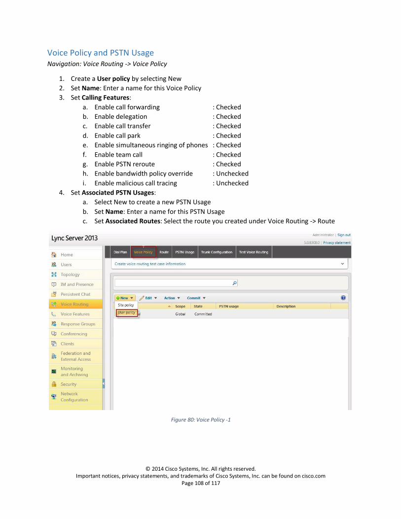
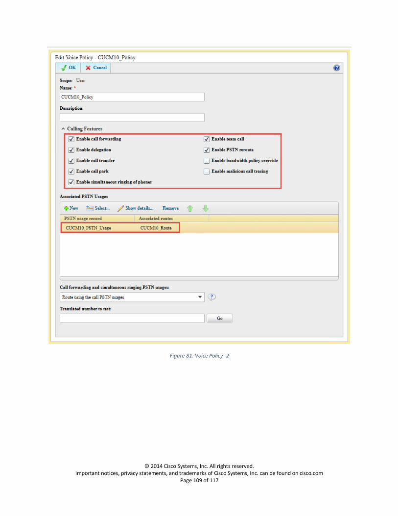
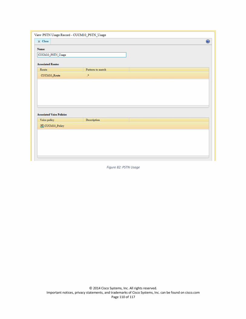
Voice Policy and PSTN Usage ........................................................................................................... 108
Dial Plan .......................................................................................................................................... 111
Configure Media Bypass .................................................................................................................. 116
Introduction This document describes the steps and configurations necessary for Cisco Unified Communications
Manager (Cisco UCM) release 10.0 to interoperate with the Lync Server 2013 using SIP. End points are
configured on both Cisco UCM and Lync Server with connectivity to PSTN. A SIP Trunk is configured
between Cisco UCM and Cisco Unity for Voicemail connectivity, Lync Server users access Cisco Unity
Voicemail via Cisco UCM.
Key Points:
The testing has been performed with only IPv4 using TCP for signaling.
CISCO UCM is connected to the PSTN network via MGCP Gateway, as seen in the topology diagram.
Basic call, call transfer with and without refer, call forwarding, conference call, call hold and resume, call park, RTCP, PRACK, Voice Mail work successfully.
Testing was performed with Cisco UCM 10.0(1), but a later release fixing the defects CSCum00523 and CSCun13435 is required to resolve REFER and Call Hold issues.
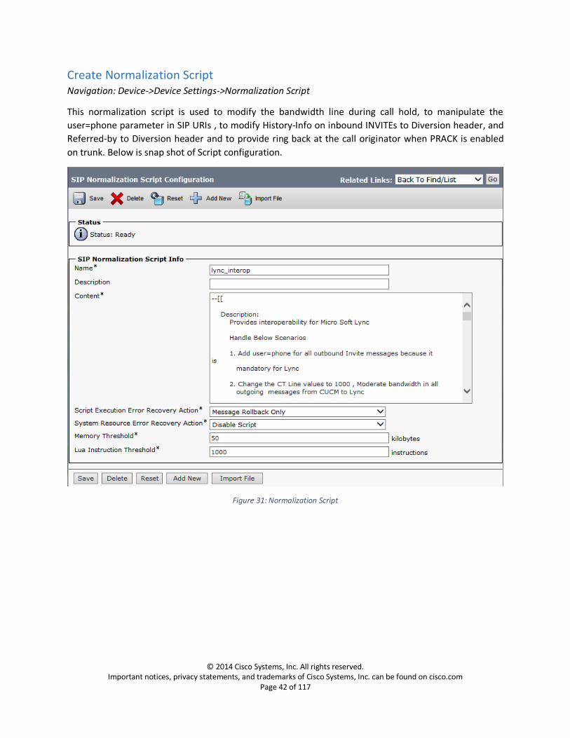
A Lua script is used to modify the bandwidth line during call hold, to manipulate the user=phone parameter in SIP URIs, to change History-Info headers in inbound INVITEs to Diversion headers, to change Referred-By headers to Diversion headers and to provide ring back at the call originator when PRACK is enabled on the SIP trunk.
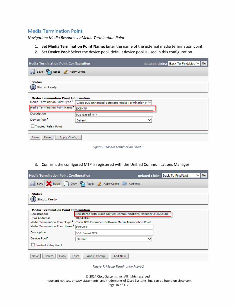
An external MTP is used on CISCO UCM to enable RTCP from CISCO UCM.
“IP RTCP Interval threshold” on MGCP gateway is changed to 5000 to prevent Lync from dropping the call while the call is on hold with MOH enabled.
Configuration of multiple SIP trunks and associated routing in Cisco UCM is necessary to support redundant Lync Mediation servers.
The following items were tested:
Basic outbound and inbound calls between Lync and PSTN through Unified Communications Manager and verification of voice path.
SIP Headers: E.164 and non-E.164, phone-context, long Request-URI
Anonymous caller representation
Codecs: G.711ulaw, G.711alaw, DTMF, Comfort Noise
Early Media: PRACK, IVR
RTP and RTCP
Call transfer: attended, early unattended (only for Cisco endpoints) and blind (only for Lync endpoints).
Message Waiting Indicator (only for Cisco Endpoints)
Features Not Supported or Not Tested:
Message Waiting Indicator on Lync Endpoints
Limitations These are the known limitations, caveats, or integration issues:
When simultaneous ring is set on Lync client to an IVR and PSTN user makes an inbound call to Lync, the call originator does not hear the early media from IVR.
No message waiting indicator on Lync for voice mail. Lync rejects the NOTIFY from Unity as it does not have ‘Notify’ as either Supported or Allowed on the call leg to Unity
Lync users do not receive Comfort Noise. Cisco provides local Comfort Noise via Cisco IP Phones and Gateways
The external MTP configured on Unified Communications Manager does not pass-through the RTCP packets coming from Lync or the MGCP Gateway when it receives a=inactive in the SDP on call hold from Lync.
When Unified Communications Manager and external MTP are configured for G.729 only and if it receives a call with G.711, Unified Communications Manager sends back a “503 Service Unavailable”
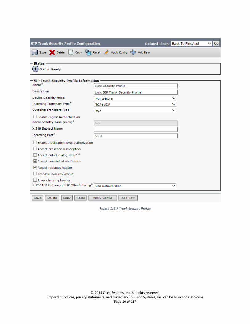
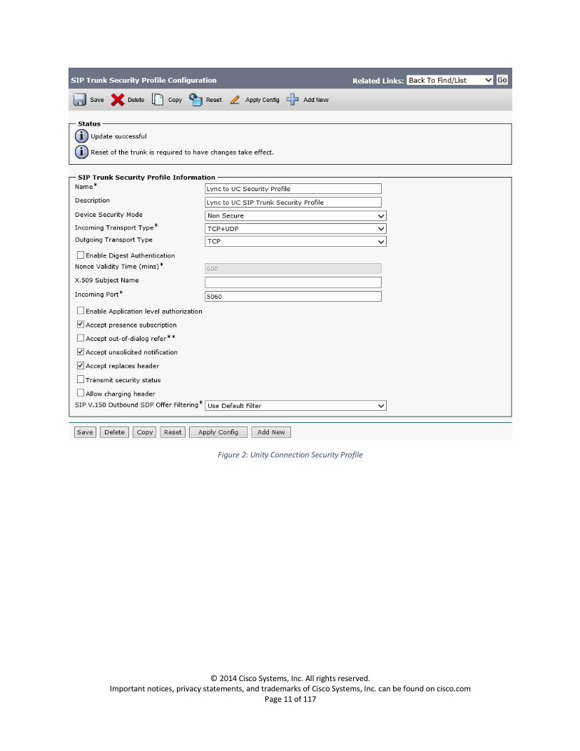
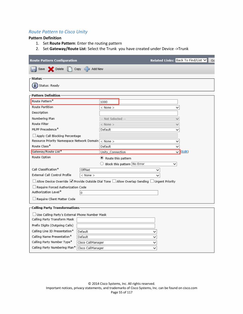
1. Set Name: Enter a name for the security profile. When you save the new profile, the name displays in the SIP Trunk Security Profile drop-down list box in the Trunk Configuration window.
2. Set Description: Enter a description relevant to your security profile
3. Confirm Accept unsolicited notification: is checked
If you want Cisco Unified Communications Manager to accept incoming non-INVITE, unsolicited notification messages that come via the SIP trunk, check this check box.
4. Confirm Accept replaces header: is checked
If you want Cisco Unified Communications Manager to accept new SIP dialogs, which have replaced existing SIP dialogs, check this check box
SIP Trunk Configuration to Lync Navigation: Device -> Trunk
Trunks are created from Unified Communications Manager to each Lync Mediation Server for trunk
failover and also to enable communications between Cisco UCM and Lync Mediation Servers. The
FQDNs are used for configuring the trunks to the Lync Mediation Servers. However, due to the current
limitation on Cisco UCM, if a SIP trunk is associated to a SIP-Route Pattern, the same trunks is not
available to be included in a Route-List. This creates a need for a duplicate set of trunks to each Lync
Mediation Server using IPv4 address. This makes the total number of trunks required to be four (two
trunks using FQDN and two trunks using IP) to enable the provisioning of Route List and SIP Route
Patterns to the Lync Mediation Servers.
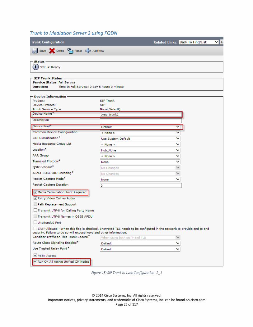
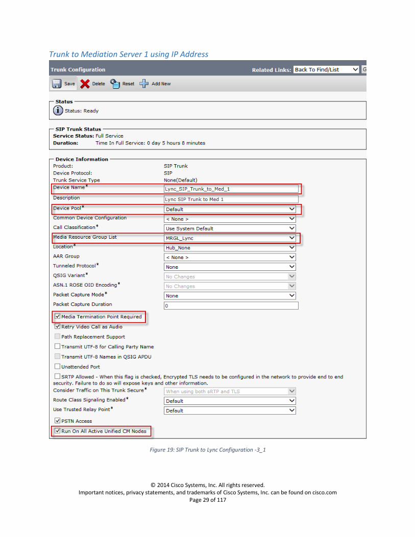
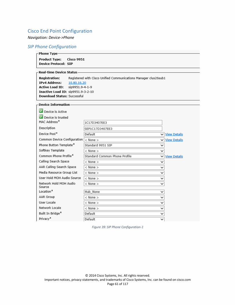
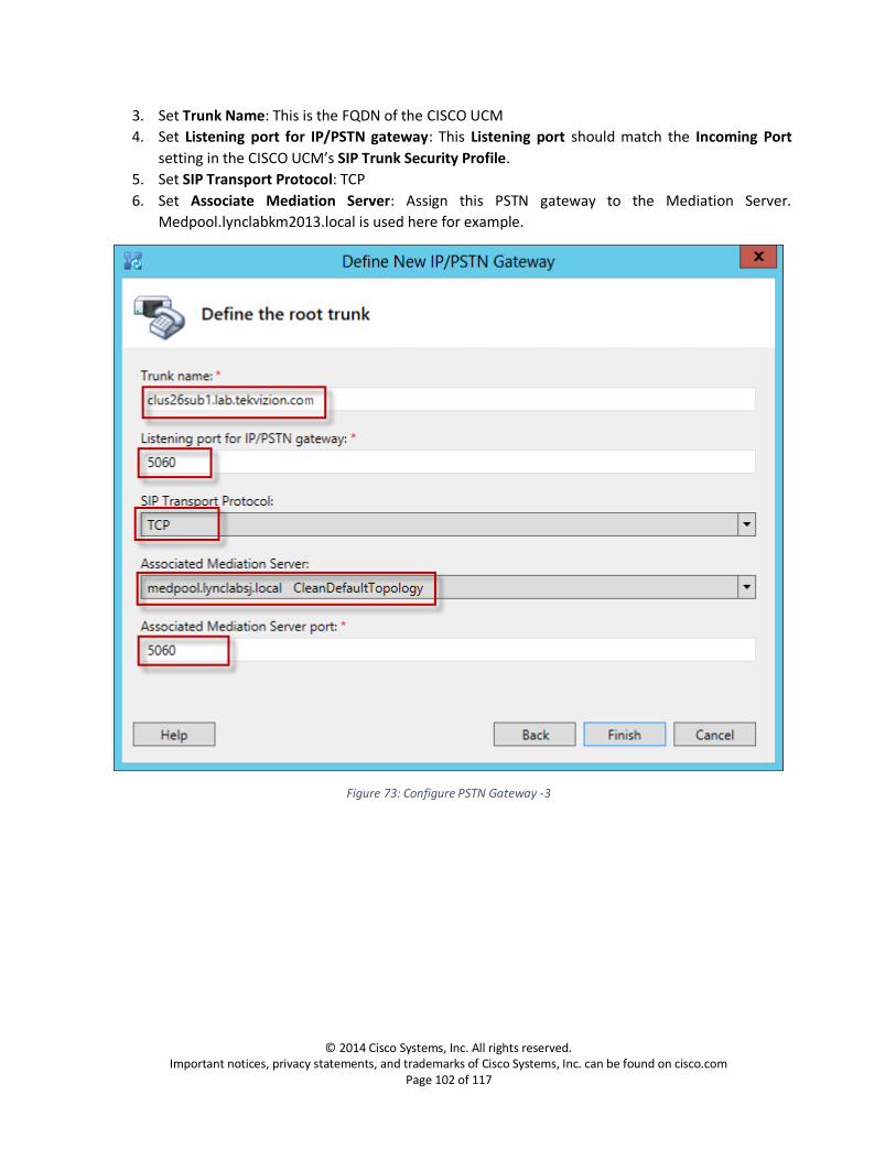
Device Information 1. Set Trunk Type: SIP Trunk 2. Set Device Protocol: SIP
3. Set Trunk Service Type: None
4. Set Device Name: Enter a name for the trunk
5. Set Description: Enter a description relevant to your trunk
6. Set Device Pool: Default
For trunks, device pools specify a list of Cisco Unified Communications Managers that the trunk uses to distribute the call load dynamically
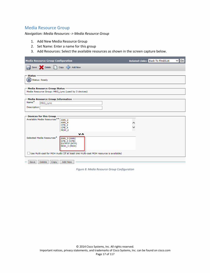
7. Set Media Resource Group List: MRGL_Lync, this is the list you created under
Media Resources -> Media Resource Group List. This list provides a prioritized grouping of media resource groups. An application chooses the required media resource, such as a Music on Hold server, from among the available media resources according to the priority order that a Media Resource Group List defines.
8. Confirm Media Termination Point Required: is checked
This check box is used to indicate whether a media termination point (MTP) is used to implement features that H.323 does not support (such as hold and transfer).
9. Confirm Retry Video Calls as Audio: is checked
10. Confirm Run On All Active Unified CM Nodes: is checked
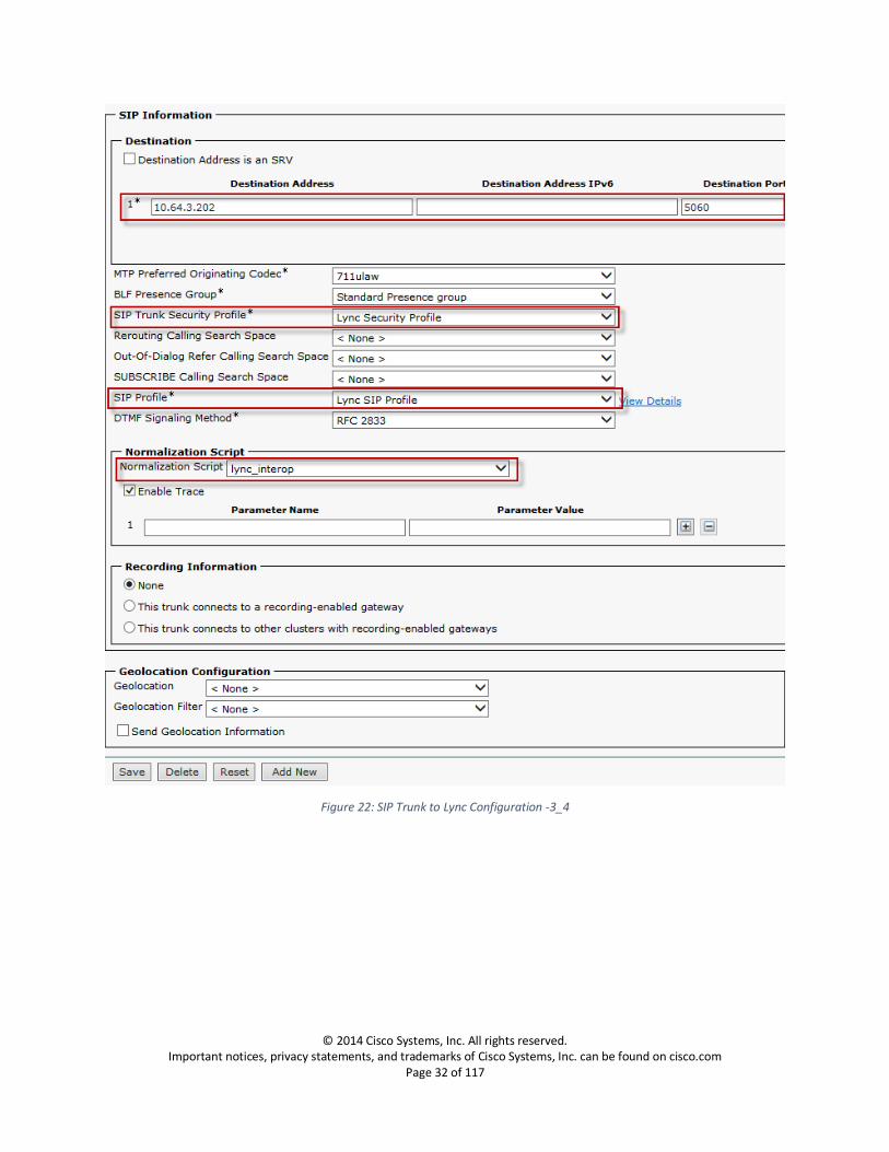
SIP Information 11. Set the Destination Address: Enter the FQDN of the Mediation Server to which you are
establishing a trunk.
12. Set SIP trunk Security Profile: Select the security profile you created under System -> Security ->
SIP Security Profile
13. Set SIP Profile: Select the SIP Profile you created under Device -> Device Settings -> SIP Profile
14. Set Normalization Script: Select the normalization script to modify the bandwidth line b=CT:64
during call hold, ring back issue with PRACK enabled.
Trunk to Cisco Unity Voice Mail Server Navigation: Device -> Trunk
The following procedure describes the trunk configuration from Unified Communications Manager to
Cisco Unity Voice Mail Server
Device Information 1. Set Trunk Type: SIP Trunk 2. Set Device Protocol: SIP
3. Set Trunk Service Type: None
4. Set Device Name: Enter a name for the trunk
5. Set Description: Enter a description relevant to your trunk
6. Set Device Pool: Default
For trunks, device pools specify a list of Cisco Unified Communications Managers that the trunk uses to distribute the call load dynamically
7. Confirm Media Termination Point Required: is checked
This check box is used to indicate whether a media termination point (MTP) is used to implement features that H.323 does not support (such as hold and transfer).
8. Confirm Retry Video Calls as Audio: is checked
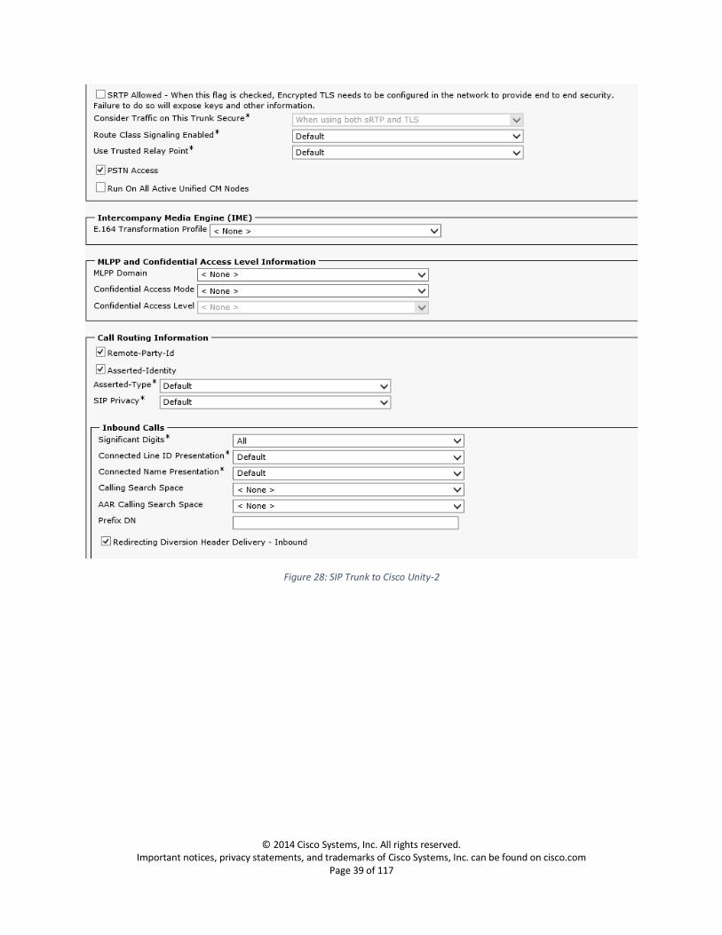
SIP Information 9. Set the Destination Address: Enter the FQDN/IP Address of the Unity Server to which you are
establishing a trunk.
10. Set SIP trunk Security Profile: Select the security profile you created under System -> Security ->
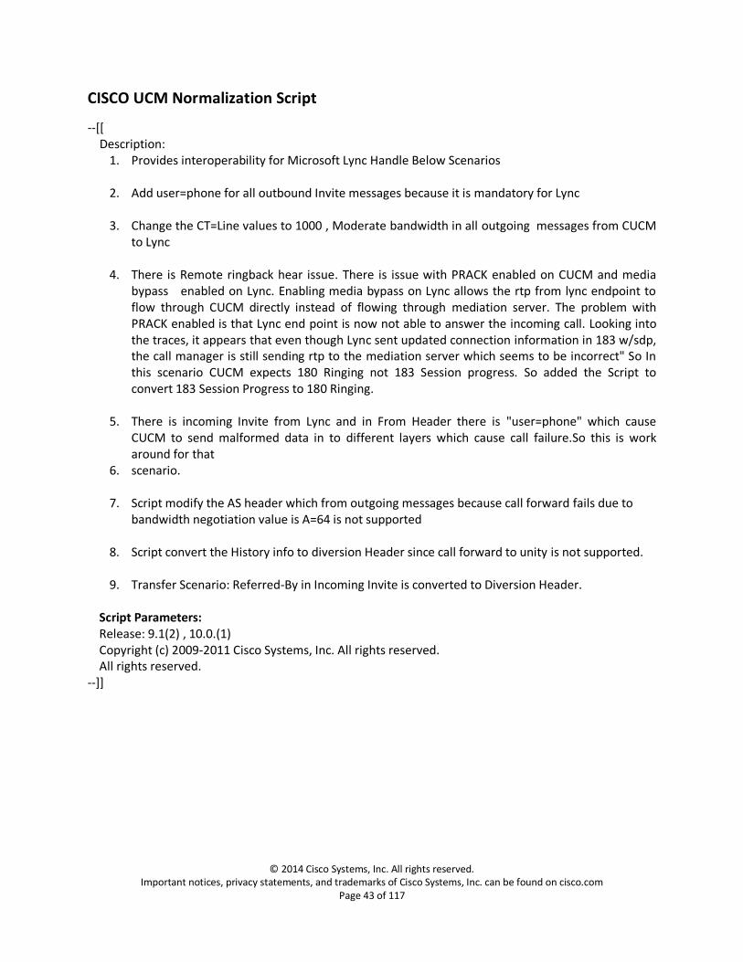
1. Provides interoperability for Microsoft Lync Handle Below Scenarios 2. Add user=phone for all outbound Invite messages because it is mandatory for Lync
3. Change the CT=Line values to 1000 , Moderate bandwidth in all outgoing messages from CUCM
to Lync
4. There is Remote ringback hear issue. There is issue with PRACK enabled on CUCM and media bypass enabled on Lync. Enabling media bypass on Lync allows the rtp from lync endpoint to flow through CUCM directly instead of flowing through mediation server. The problem with PRACK enabled is that Lync end point is now not able to answer the incoming call. Looking into the traces, it appears that even though Lync sent updated connection information in 183 w/sdp, the call manager is still sending rtp to the mediation server which seems to be incorrect" So In this scenario CUCM expects 180 Ringing not 183 Session progress. So added the Script to convert 183 Session Progress to 180 Ringing.
5. There is incoming Invite from Lync and in From Header there is "user=phone" which cause
CUCM to send malformed data in to different layers which cause call failure.So this is work around for that
6. scenario.
7. Script modify the AS header which from outgoing messages because call forward fails due to bandwidth negotiation value is A=64 is not supported
8. Script convert the History info to diversion Header since call forward to unity is not supported.
9. Transfer Scenario: Referred-By in Incoming Invite is converted to Diversion Header.
Script Parameters: Release: 9.1(2) , 10.0.(1) Copyright (c) 2009-2011 Cisco Systems, Inc. All rights reserved. All rights reserved. --]]
M = {} M.allowHeaders = {"History-Info"} -- trace.enable() local function modify_CT_bandwidth(msg) local sdp = msg:getSdp() if sdp then local b_CT_line = sdp:getLine("b=CT","64") if not b_CT_line then local b_CT_line = sdp:getLine("b=CT","0") if not b_CT_line then return end b_CT_line = b_CT_line:gsub("0", "1000") sdp = sdp:modifyLine("b=CT", "0", b_CT_line) msg:setSdp(sdp) return end b_CT_line = b_CT_line:gsub("64", "1000") sdp = sdp:modifyLine("b=CT", "64", b_CT_line) msg:setSdp(sdp) end end local function remove_AS_bandwidth(msg) local sdp = msg:getSdp() if sdp then local b_AS_line = sdp:getLine("b=AS","64") if b_AS_line then sdp = sdp:removeLine("b=AS", "64") msg:setSdp(sdp) end end end local function process_outbound_request(msg) local method, ruri, ver = msg:getRequestLine() if string.find(ruri, "@")
then local uri = ruri .. ";user=phone" msg:setRequestUri(uri) end modify_CT_bandwidth(msg) remove_AS_bandwidth(msg) end local function process_outbound_message(msg) modify_CT_bandwidth(msg) remove_AS_bandwidth(msg) end local function process_inbound_progress(msg) msg:setResponseCode(180, "Ringing") local req = msg:getHeader("Require") local reqHeader = req if req then msg:removeHeader("Require") end local rseq = msg:getHeader("Rseq") local rseqPresnt = rseq if rseq then seqVal = msg:getHeaderValues("Rseq") msg:removeHeader("Rseq") end local sdp = msg:getSdp() if sdp then msg:removeUnreliableSdp() end if reqHeader then msg:addHeader("Require", "100rel") end if rseqPresnt
then msg:addHeader("RSeq",seqVal[1]) end end -- Future reference for changing cause values in divertion header scenario -- local HiCauseToDiversion = { } -- HiCauseToDiversion["302"] = "unconditional" -- HiCauseToDiversion["486"] = "user-busy" -- HiCauseToDiversion["408"] = "no-answer" -- HiCauseToDiversion["480"] = "deflection" -- HiCauseToDiversion["487"] = "deflection" -- HiCauseToDiversion["503"] = "unavailable" -- HiCauseToDiversion["404"] = "unknown" function convertHIToDiversion(msg) local historyInfos = msg:getHeaderValues("History-Info") for i, hi in ipairs(historyInfos) do hi = string.gsub(hi, "%%3B", ";") hi = string.gsub(hi, "%%3D", "=") hi = string.gsub(hi, "%%22", "\"") hi = string.gsub(hi, "%%20", " ") -- MS format: <sip:[email protected];user=phone>;index=1;ms-retarget-reason=forwarding local uri, index, reason = string.match(hi, "<(sip:.*@.*)>;index=(.*)reason=(.*)") trace.format("hi: uri '%s', reason '%s'", uri or "nil", reason or "nil") if uri then local diversion = string.format("<%s>", uri) if reason then diversion = string.format("<%s>;reason=\"unconditional\"", uri) end msg:addHeader("Diversion", diversion) end end end function convertReferredByToDiversion(msg)
local refInfo = msg:getHeader("Referred-By") if refInfo then local diversion = string.format("%s;reason=\"unconditional\"", refInfo) msg:addHeader("Diversion", diversion) end end local function replaceHistoryHeader(msg) local hist = msg:getHeader("History-Info") if hist then convertHIToDiversion(msg) local di = msg:getHeader("Diversion") if di then msg:removeHeader("History-Info") end end end local function replaceReferredByHeader(msg) local refby = msg:getHeader("Referred-By") if refby then convertReferredByToDiversion(msg) end end local function modifyUserFrom(msg) -- get a data from "From" header and replace local removeUser= "" local value = msg:getHeader("From") if value then value = value:gsub(";user=phone", removeUser) if value then
msg:modifyHeader("From", value) end end end local function process_inbound_request(msg) modifyUserFrom(msg) replaceHistoryHeader(msg) replaceReferredByHeader(msg) end M.outbound_INVITE = process_outbound_request M.outbound_ACK = process_outbound_message M.outbound_200_INVITE = process_outbound_message M.outbound_18X_INVITE = process_outbound_message M.inbound_183_INVITE = process_inbound_progress M.inbound_INVITE = process_inbound_request return M
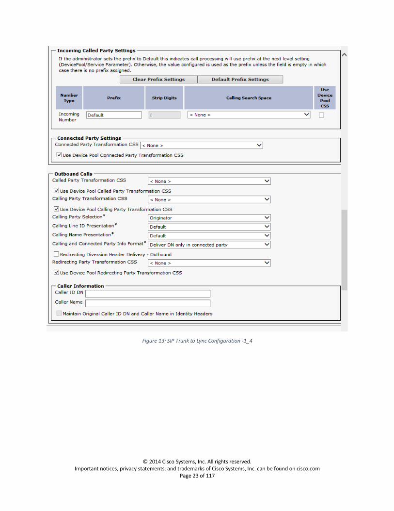
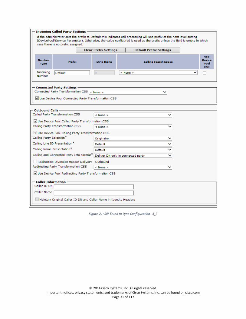
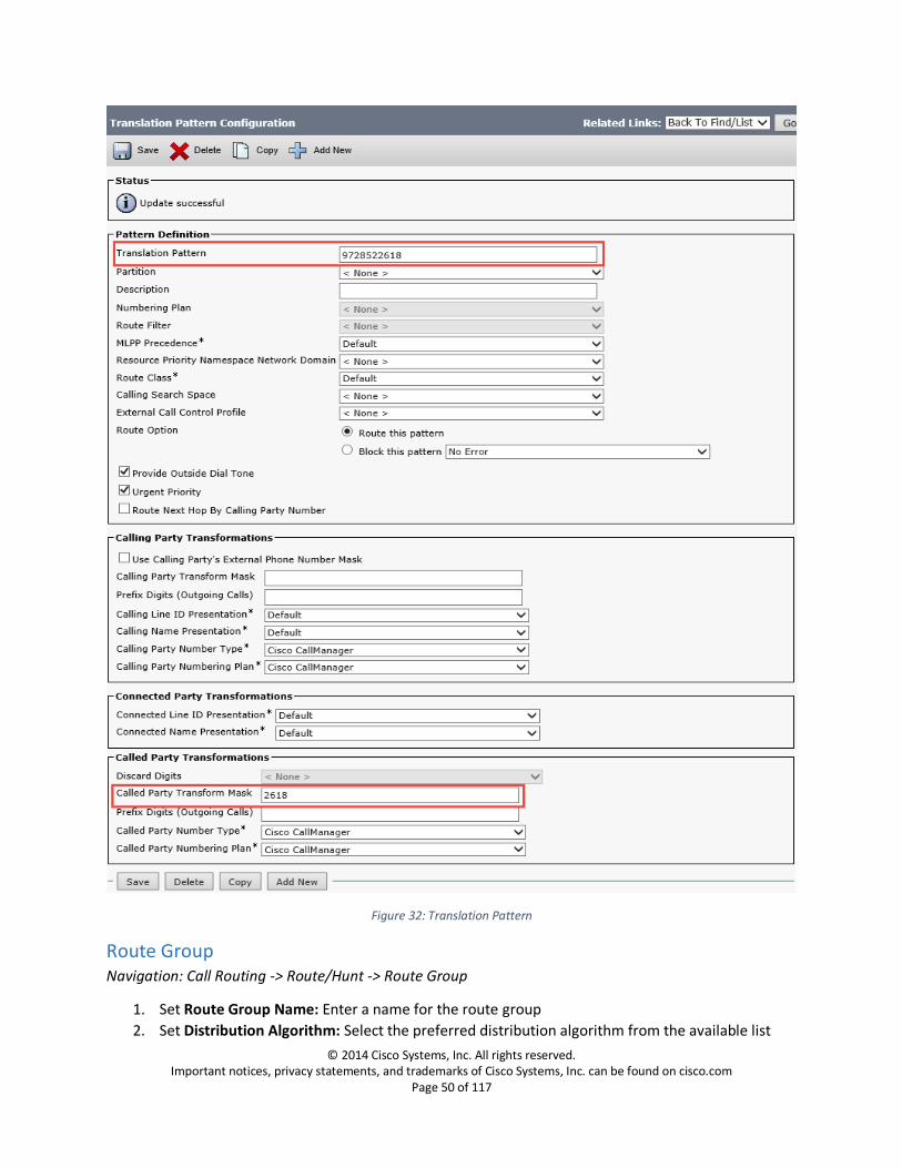
1. Set Translation Pattern: Enter the ten digit number pattern to be translated 2. Set Called Party Transform Mask: Enter the four digit number pattern to be translated to, these
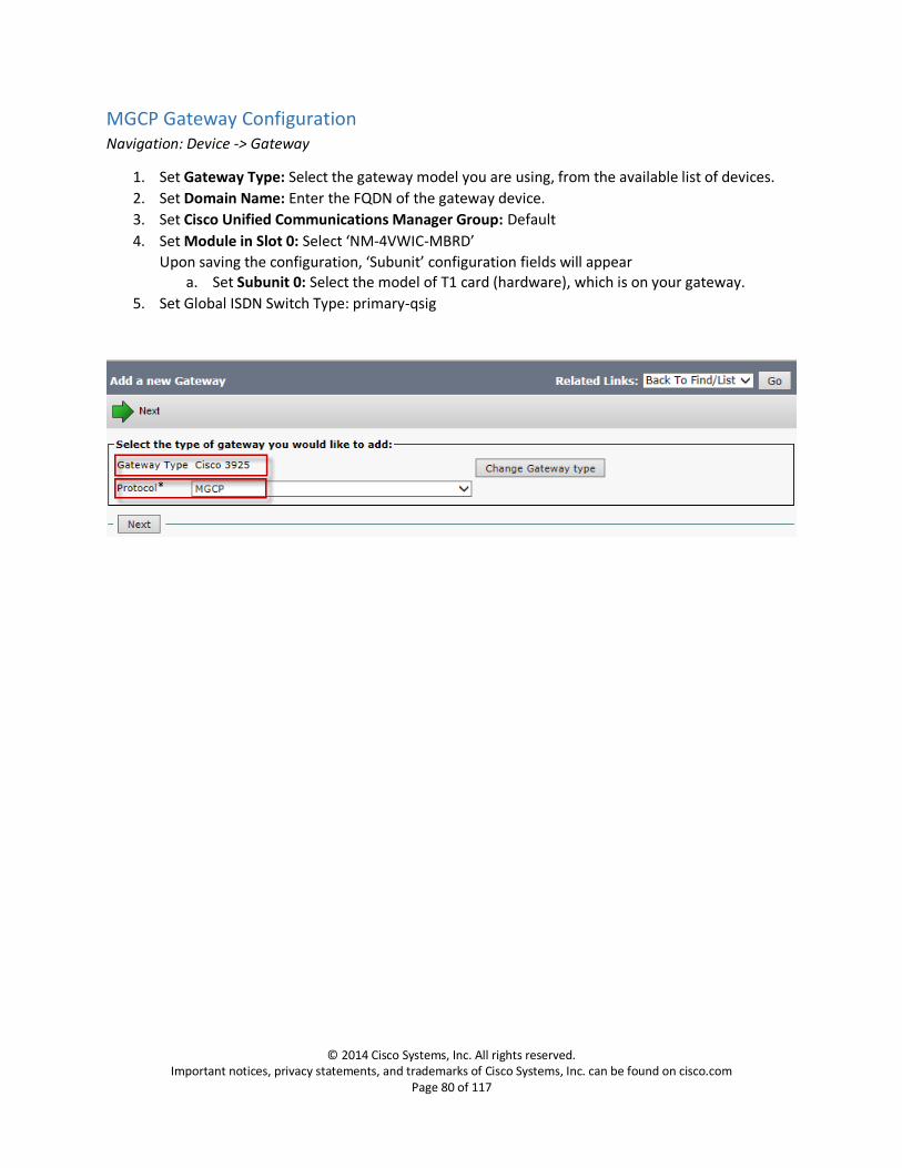
1. Set Gateway Type: Select the gateway model you are using, from the available list of devices.
2. Set Domain Name: Enter the FQDN of the gateway device.
3. Set Cisco Unified Communications Manager Group: Default
4. Set Module in Slot 0: Select ‘NM-4VWIC-MBRD’
Upon saving the configuration, ‘Subunit’ configuration fields will appear a. Set Subunit 0: Select the model of T1 card (hardware), which is on your gateway.
Phone System Configuration Navigation: Telephony Integrations -> Phone System
1. Set Phone System Name: Enter a name for the phone system 2. To navigate to the next step of configuration, move to related links ‘Add Port Group’ and click
Port Group Configuration Navigation: Telephony Integrations -> Port Group
1. Set Phone System: Select the phone system configured in the above section 2. Set Create From Port Group Type: SIP 3. Set SIP Security Profile: 5060 4. Set SIP Transport Protocol: TCP
Port Configuration Navigation: Telephony Integrations -> Port
1. Set Port Name: Enter Name for the port 2. Set Phone System: Select the phone system which you are creating the ports to 3. Set Port Group: Select the port group configured to the phone system selected in the above step 4. Set Server: Select the unity server
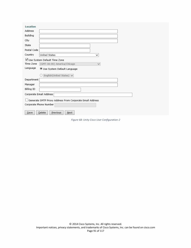
Cisco Unity User Configuration Navigation: Users -> Users
1. Set Alias: Enter a name for the user 2. Set Extension: Enter the extension you are configuring this user for 3. Set Phone System: Select the phone system you configured under Telephony Integrations->
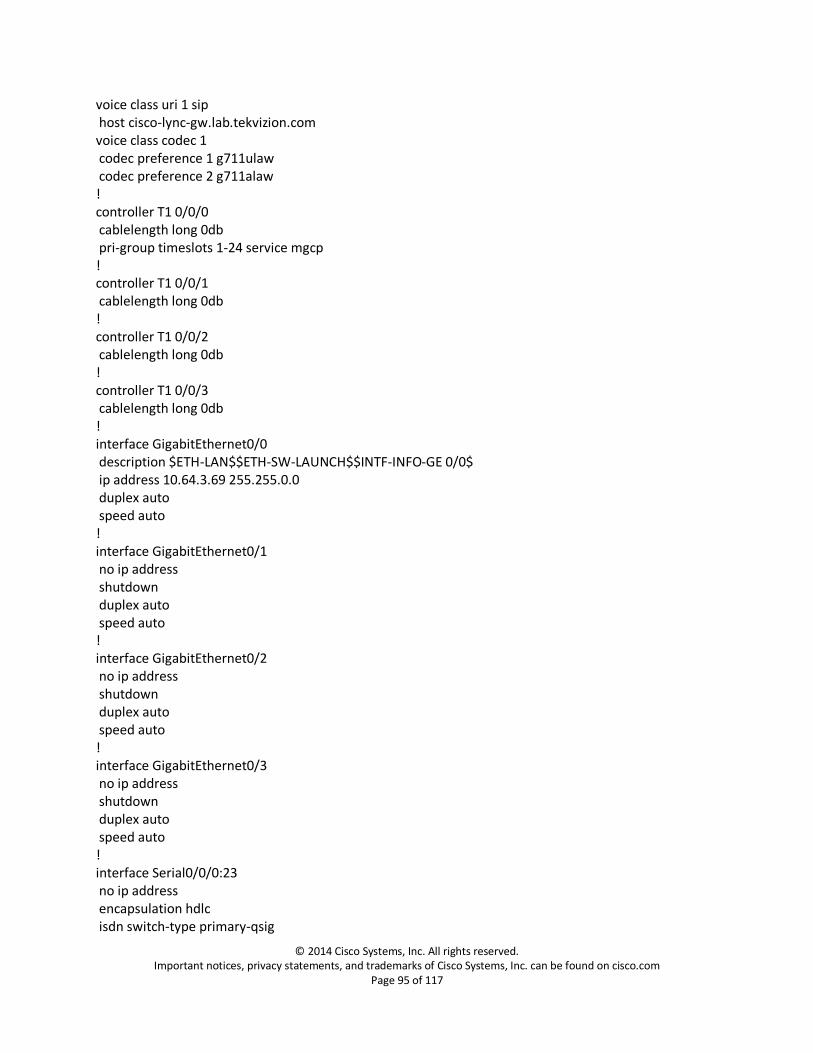
Gateway Configuration version 15.4 service timestamps debug datetime msec service timestamps log datetime msec no service password-encryption service sequence-numbers ! hostname cisco-lync-gw ! boot-start-marker boot system flash c3900e-universalk9-mz.SPA.154-1.T.bin boot-end-marker ! aqm-register-fnf ! card type t1 0 0 logging buffered 999999999 no logging rate-limit no logging console enable secret 4 sKPgCY/XPea3wk8xoeSWo7UGFaNVwzXDEyXWhuDjeLk ! no aaa new-model ! network-clock-participate wic 0 network-clock-select 1 T1 0/0/0 ! ip domain name lab.tekvizion.com ip name-server <name-server IP address> ip cef no ipv6 cef ! multilink bundle-name authenticated ! isdn switch-type primary-qsig ! voice-card 0 dsp services dspfarm ! voice service voip ip address trusted list ipv4 0.0.0.0 0.0.0.0 sip session transport tcp header-passing asserted-id pai !
voice class uri 1 sip host cisco-lync-gw.lab.tekvizion.com voice class codec 1 codec preference 1 g711ulaw codec preference 2 g711alaw ! controller T1 0/0/0 cablelength long 0db pri-group timeslots 1-24 service mgcp ! controller T1 0/0/1 cablelength long 0db ! controller T1 0/0/2 cablelength long 0db ! controller T1 0/0/3 cablelength long 0db ! interface GigabitEthernet0/0 description $ETH-LAN$$ETH-SW-LAUNCH$$INTF-INFO-GE 0/0$ ip address 10.64.3.69 255.255.0.0 duplex auto speed auto ! interface GigabitEthernet0/1 no ip address shutdown duplex auto speed auto ! interface GigabitEthernet0/2 no ip address shutdown duplex auto speed auto ! interface GigabitEthernet0/3 no ip address shutdown duplex auto speed auto ! interface Serial0/0/0:23 no ip address encapsulation hdlc isdn switch-type primary-qsig